Failure Prediction for Static Loading
- 格式:dps
- 大小:2.11 MB
- 文档页数:35

钢筋混凝土梁疲劳累积损伤过程的等效静力分析方法王青;卫军;刘晓春;徐港【摘要】In order to achieve the full-range analysis and prediction of residual bearing capacity of concrete beams under high-cycle fatigue loading effectively, an equivalent static analysis method for fatigue cumulative damage process of concrete member was proposed. Firstly, according to the rules on stiffness degradation, strength reduction and the accumulation of residual deformation of materials under the fatigue loading, fatigue constitutive model of concrete and reinforced rebar in any cycle of the fatigue load were established. Based on the similarity of concrete behavior under static load and that under fatigue load, the equivalent relation was built. The equivalent static analysis method for fatigue performance of reinforced concrete member was proposed. A reinforced concrete simple-supported beam was simulated for the fatigue behavior by the method as an example. The results show that the numerical analysis results are consistent with the test results. The effectiveness and practicability are testified.%为了实现对钢筋混凝土梁疲劳性能的全过程分析和剩余承载力评估,提出一种混凝土构件疲劳累积损伤过程的等效静力分析方法。

abaqus johnson cook失效准则Abaqus Johnson-Cook Failure Criterion: An In-depth AnalysisIntroduction:The Abaqus Johnson-Cook failure criterion is widely used in the field of computational modeling and simulation to predict material failure under extreme conditions. This criterion is paramount in accurately predicting how a material will deform and eventually fail under various loading conditions. In this article, we will provide a step-by-step analysis of the Abaqus Johnson-Cook failure criterion, its underlying principles, and its applications in engineering simulations.1. Background and Theory:The Johnson-Cook failure criterion was originally proposed by G.R. Johnson and W.H. Cook in 1983. It provides a phenomenological representation of the material behavior leading to failure under high strain rates and elevated temperatures. The criterion takes into account the effects of strain, strain rate, and temperature on the material's response to loading. By considering these factors, thefailure criterion allows for a more accurate prediction of material failure.2. Formulation of the Criterion:The Abaqus Johnson-Cook failure criterion can be mathematically represented as follows:σ_eq = (1 + αε˙_pl^* (T - T_0))^m (1 - β(T - T_0))^nwhere σ_eq is the equivalent stress, αand βare material constants, ε˙_pl^* is the plastic strain rate, T is the temperature, T_0 is a reference temperature, and m and n are exponent parameters. This equation describes the relationship between stress, strain rate, temperature, and material failure.3. Parameter Determination:To accurately define the material constants α, β, m, and n, experimental data is necessary. These constants are typically obtained through a series of experimental tests, such as tensile tests at different strain rates and temperatures. The results fromthese tests are then used to fit the parameters in the Johnson-Cook equation to obtain a reliable representation of the material behavior.4. Material Model Implementation:In Abaqus, the Johnson-Cook failure criterion is implemented through a specific material model. The material model incorporates the Johnson-Cook equation and provides a framework to simulate the behavior of materials subjected to high strain rates and elevated temperatures. The user must input the relevant material properties and the determined values for α, β, m, and n into the material model.5. Applications:The Abaqus Johnson-Cook failure criterion has found numerous applications across various engineering disciplines. It is particularly relevant in the fields of impact dynamics, projectile penetration, blast effects, and metal forming processes. By accurately predicting material failure, engineers can design structures and components with a higher level of safety and durability.6. Validation and Verification:Before utilizing the Abaqus Johnson-Cook failure criterion in engineering simulations, it is crucial to validate and verify the accuracy of the material model. This involves comparing the simulation results with experimental data obtained from laboratory tests. If the simulation results closely match the experimental results, it provides confidence in the predictive capability of the model.7. Advantages and Limitations:The Abaqus Johnson-Cook failure criterion allows engineers to simulate and predict material failure under extreme conditions, providing valuable insights for design and analysis purposes. However, it is important to note that the accuracy of the model heavily relies on accurate parameter determination and appropriate material model selection. Additionally, the criterion may not be suitable for all materials and certain scenarios, necessitating the use of alternative failure criteria.Conclusion:In conclusion, the Abaqus Johnson-Cook failure criterion is a valuable tool in predicting material failure under high strain rates and elevated temperatures. By considering the effects of strain, strain rate, and temperature in the material's response to loading, this criterion provides engineers with important insights during the design and analysis stages. However, it is crucial to accurately determine the material constants and validate the model to ensure reliable predictions. The Abaqus Johnson-Cook failure criterion continues to play a pivotal role in engineering simulations, contributing to safer and more efficient designs.。
第29卷第1期硅酸盐学报VoI.29,No.1 2001年2月JOURNAL OF THE CHINESE CERAMIC SOCIETY February,! !!!!!!!!!!!!!!!!!!!!!!!!!!!!!!!!!!!!!!!!!!!!!!!!!!!!!!!!!!!!!!2001氧化铝、氮化硅和碳化硅的疲劳特性与寿命预测包亦望(中国建筑材料科学研究院,北京100024)摘要:分析了几种典型的结构陶瓷在长期载荷下的失效特性和差别.认为长期失效的本质是强度衰减,建立了一个疲劳失效的强度衰减模型和提出了寿命预测方法.分别研究了氧化铝、氮化硅和碳化硅几种常用工程陶瓷在常温和高温下的疲劳特性和差异.采用三点弯曲的受力方式测试了不同载荷水平下的断裂时间.结果表明:碳化硅的疲劳门槛值超过强度的80%,而且受温度影响最小;氧化铝的静疲劳受微小裂纹扩展控制;氮化硅的高温疲劳主要是蠕变机制导致强度衰减,疲劳门槛值不超过强度的50%.由实验研究了氮化硅的高温静疲劳、动疲劳和循环疲劳三者在相同温度和相同应力峰值条件下的寿命关系,结果与计算一致.关键词:陶瓷;寿命预测;疲劳;强度衰减中图分类号:TB321;TO174.54文献标识码:A文章编号:0454-5648(2001)01-0021-05FAILURE BEHAVIORS AND LIFETIME PREDICTION OF A O3,SiC and HP-Si3N4Bao Yiwang(China BuiIding MateriaIs Academy,Beijing100024)Abstract:Fatigue behavior of three ceramics materiaIs AI2O3,SiC,HP-Si3N4and their differences were investigated.The study confirmes that the Iong-term faiIure of ceramics is due to the strength degradation that can be caused by various factors.A modeI of strength degradation for faiIure evaIuation is presented and the Iifetime caIcuIation can be simpIified as a motion eguation.Static fatigue behaviors of AI2O3,SiC,HP-Si3N4,and their difference at room temperature and high temperature,were investigated experimentaIIy.The Iifetimes under different Ioading IeveIs were measured by means of three-point bending method.The resuIts show that the fatigue threshoId of SiC is much higher than that of the other two materiaIs and has no dependence on temperature.The fatigue Iifetime of aIumina is controIIed mainIy by subcriticaI crack growth,and the fatigue faiIure of siIicon nitride at high temperature is due to strength degradation caused by creep.The reIations between Iife-time and Ioads measured for aIumina and siIicon nitride are consistent with the predicted by the modeI of strength degradation.It is found that the data of Iifetime of SiC greatIy scatter and fatigue threshoId is over80%of strength.The Iifetime reIations of Si3N4under static,cycIic and dynamic fatigue at1200C were tested and the resuIts agree weII with caIcuIation resuIts.Key words:ceramics;Iifetime prediction;fatigue;strength degradation陶瓷材料的疲劳定义与金属有点差别,不仅循环疲劳称为疲劳,静载荷下的应力腐蚀称为静疲劳,加载速率为常量的线性增加载荷称为动疲劳[1].一般认为,陶瓷的失效是由于众多微缺陷中逐渐发展出来一条主裂纹,尔后主裂纹亚临界扩展收稿日期:2000-03-15.基金项目:国家自然科学基金资助项目(59872035).作者简介:包亦望(1957~),男,工学博士,研究员,博士生导师.达到临界状态最后断裂.但许多陶瓷是主裂纹一出现立刻断裂,慢裂纹扩展很难观测到,有些阻力曲线测试也是裂纹一起始就快速卸载来避免失稳断裂[2].陶瓷是否存在疲劳效应也一直有争议.实际上,不同的陶瓷材料有不同的疲劳特性和不同的疲Received date:2000-03-15.Biography:Bao Yiwang(1957—),maIe,doctor,professor.劳门槛值以及各自适合的寿命计算模型,没有一个失效理论或模型能够适合于所有的陶瓷材料.氧化铝是最为广泛和大量应用在工业界的结构陶瓷,它存在一定的阻力特性.热压氮化硅具有较高强度和韧性,是刀具和轴承球的理想材料.碳化硅是优良的高温结构材料,但脆性较大.本研究重点对这3种结构陶瓷的疲劳特性进行了实验.1强度衰减与失效评价大部分陶瓷的慢裂纹扩展实验非常困难.因此,用裂纹扩展模型分析陶瓷的寿命在操作上和可靠性方面有相当难度[3].而用强度衰减理论进行寿命预测是一个值得重视的方向.在给定的载荷和环境条件下,如果强度衰减速率已知,就可以很容易评价寿命.由于残余强度是时间的减函数并且总是高于外加载荷,在一定时间后当残余强度衰减到与外加载荷相等时将发生断裂,这个衰减过程所用的时间便是工作构件的寿命.当强度和外载荷都是时间的函数时,2条函数曲线的交点为断裂点.强度衰减速率通常与实验条件、作用应力和受载时间有关,可表示为[4]c!c z=-B·P N·z-m(1)式中:B,N,m均为非负常数,与材料性能和实验环境有关;!为随时间变化的残余强度;P为外应力.对于静载荷,材料的强度可看作变量,外加应力是常数.设材料的原始强度为!0,则有初始条件!(z0)=!0(2)断裂条件!(z f)=P式中:z0是失稳断裂的微小时间量.积分式(1)并考虑初始条件,可得到残余强度表达式.考虑断裂条件,可确定出断裂时的时间.限于篇幅,这里只考虑许多服从线性损伤积累(m=0)的情况.跟寿命相比,微小z0可忽略不计,从而得到静载荷下的寿命表达式z S=!0-PB·P N(3)式中:!0-P是试件在破坏时的强度损失.它表明寿命不仅与外载荷有关,还跟原始强度有关.对于动疲劳,P(z)=Cz,是时间的线性函数,将该函数代入式(1)可求得对应的残余强度表达式和寿命方程.例如,对于m=0的线性衰减情况,动疲劳的寿命可表示为z c=!0-!cB·!N c(N+1)(4)式中:!c为动疲劳(载荷下发生断裂时刻的应力值).对于周期为T的对称三角波循环疲劳载荷,设每个循环产生的损伤是相等的,则只要知道第一个循环载荷的函数形式,代入强度衰减方程积分得任意时刻(z=iT)的残余强度,设残余强度衰减到循环应力的峰值时发生断裂,可得到三角波循环疲劳下的寿命表达式为z c=!0-!maxB·!N max(1-R)(N+1)1-R N+1(5)式中:!max为三角波循环疲劳中的最大应力;R为循环疲劳中的应力比.容易看出,对于0<R<1,而且最大载荷相等的情况下,静疲劳、循环疲劳和动疲劳的寿命有如下关系:z S1z c1z c=11(N+11+R+R2+…+R N)1(N+1)(6)式(6)说明在相同的最大载荷下,静疲劳的强度衰减最快,循环疲劳次之,动疲劳的强度衰减最慢.它反映了有些陶瓷疲劳的依时性而非依赖加载次数.必须强调,以上寿命评价理论仅代表了一种失效规律,所以它只适合于某一类情况.经验表明,在静载荷下强度逐渐衰减的陶瓷最适合此模型.疲劳寿命过程可看作为一种运动状态,而断裂失效是以这种运动从初始值到达某种临界状态为判据.因此,寿命的评价可以简化成一个运动方程.运动的距离是已知的.2实验与讨论实验采用的3种结构陶瓷材料测试的基本性能列于表1中.试样用外圆切片机切割,经研磨并抛光受拉面,制成国标规定的弯曲强度试样尺寸3mm X4mm X36mm,跨距为30mm,强度和残余强度测试的标准加载速率为0.5mm/min,常规表13种陶瓷试样的基本力学性能Table1Basic mechanical properties of three typesof ceramicsMateriaIE/GpaGrain Size/!m!b/MpaK"c/(Mpa·m1/2)AI20330010~30172 3.0SiC2956~10178 2.5Hp-Si3N43103~6680 6.422硅酸盐学报2001年性能在岛津AG-10TA万能材料试验机上进行.静疲劳试验在杠杆式疲劳试验机上完成,采用砝码加载,自动记录断裂时间.室温下测试了氧化铝和碳化硅2组试样的静疲劳寿命以及30h左右仍未断的试样的残余强度.高温疲劳试验主要针对碳化硅和热压氮化硅.2.1氧化铝和碳化硅的常温静疲劳氧化铝陶瓷的断裂阻力在空气中受湿度[5]和加载速度的影响较大,表现为加载速度越高,所测的弯曲强度越高.这种特性表明它内部存在微裂纹的亚临界扩展[2]和应力腐蚀[6].实验采用4种不同的加载速率(国标规定0.5mm/min),每组试样12条,得到的平均强度相差较大,如表2所示.从表2的结果来看,氧化铝具有较明显的疲劳特性,使强度随加载时间延长而较快地衰减,所以加载速度越慢,所测得强度越低.相比之下,碳化硅没有这种疲劳特性.当采用加载速度分别为0.05,0.5,5 mm/min对碳化硅进行弯曲强度试验时,所得每组的平均强度几乎一致,不受载荷速率影响,约为178Mpa左右.这里所指的载荷速率影响是在静力学范围内,若考虑高速冲击,由于惯性力等因素,瞬态断裂应力可达到很高[7].表2氧化铝弯曲强度随加载速度的变化Table2Variation of bending strength of alumina with loading ratesCross-head rate /(mm·min-1)Mean strength/MpaStandard deviation/Mpa0.0515511.40.517213.3218420.1519914.4碳化硅的静疲劳的规律性不象氧化铝那么明显,在不同水平的载荷下都有一些试样在规定的30 h内仍不断裂,将这些残存未断的试样进行强度测试,发现它们的平均残余强度不仅不比原始强度低,反而略高于碳化硅的原始强度平均值.若将实验中试样断裂的时间近似作为寿命,氧化铝和碳化硅的静疲劳寿命跟载荷水平的关系见图1.碳化硅静疲劳试验的寿命以及残存未断试样的残余强度测试值见表3.从残余碳化硅试样的强度来看,它在静疲劳过图1不同载荷下AI203(!=5,"=7#75X10-12,$=0)和SiC(不适于强度衰减模型)实验结果Fig.1ExperimentaI resuIts of static fatigue under different Ioads for AI203(!=5,$=0,"=7.75X10⁻¹²)and SiC(unsuitabIe for the strength degradation modeI)表3碳化硅在不同静载荷下的断裂时间和部分残存试件的残余强度Table3Fracture time and residual strength of survival SiC samples under different static loadsSampIeNo.Strees/MpaTime tofracture/sNo fracture untiIthe time/sResiduaIstrength/Mpa 11001080001802100108000162310010800018741407036514090000172614010800016471401080001998140648091402397010140100000169111401080001861214090000165131401080001901414010430515140456716150279671715064751815067356191501000001902015089436245程中几乎没有损伤发展和强度衰减.为了考察一根32第29卷第1期包亦望:氧化铝、氮化硅和碳化硅的疲劳特性与寿命预测经301(150Mpa)未断的试样能否在更长的时间断裂,将该载荷长时间保持直至3601,但仍未出现断裂,最后测得残余强度还有180Mpa.这说明载荷低于80%强度值时这种材料几乎没有静疲劳效应.而另一方面,又确实有部分试样在受载荷经历一段时间后发生断裂,而不是加载后立刻断裂.这是由于陶瓷的强度值有较大的离散性,在疲劳试验中那些强度低(只比外载荷高一点)的试样最终都断了,因为载荷已接近它的强度值.残余强度平均值的计算时不含低强度的试样,故残余强度平均值反而高于原始强度的平均值.以上实验结果表明碳化硅不是没有疲劳效应,只是疲劳门槛值非常高.由于强度的离散性,相同的外载荷对某些试样是高于疲劳门槛值,对某些试样是低于疲劳门槛值.于是强度的离散性导致了寿命更大的离散性.因此,强度的WeibuII模数与寿命的WeibuII模数不是一回事,有时相差很大.虽然氧化铝和碳化硅的强度值差不多,但由于碳化硅的疲劳门槛值很高,寿命更长得多.2.2碳化硅和热压氮化硅的高温疲劳寿命由于陶瓷的应用常常是在高温条件下,故高温疲劳特性的研究和实验数据有实际参考价值.本实验表明,SiC在高温下强度有所提高,没有蠕变和裂纹扩展迹象,仍为突发性脆断.在1200C和1370C高温下的静载荷-寿命关系见图2.从实验结果来看寿命数据的分散性较大,这主要由于材料微观缺陷分布不均匀和脆性材料对缺陷的敏感性.从总的趋势来看,SiC的强度和疲劳特性受温度影响不大,是耐高温部件的首选材料.实验的另一种陶瓷是作为刀具材料的热压氮化硅,这种陶瓷具有较好的常温性能.在1000C以下强度变化很小.在1200C的三点弯曲强度为360 Mpa.但由于存在少量晶界玻璃相,在静载荷下会发生缓慢蠕变变形和晶界强度下降而产生强度衰减[8].因此实际寿命变化规律较好地符合强度衰减模型,1200C下的寿命-静载荷关系数据通过最小二乘拟合得到疲劳参数!=5.4X10⁻¹⁴,"=5. 96,#=0.实验数据和寿命计算曲线比较见图3.实验残片断口分析和$射线衍射成分分析表明:热压氮化硅的高温失效主要由于晶界玻璃相的粘滞流动和少量高温氧化作用;这种高温玻璃相可导致蠕变残余变形,同时使晶界强度下降,产生硬晶粒软晶界现象.图4显示了氮化硅和碳化硅试样在1200C高温和120Mpa弯曲载荷下经361降温卸载后的残余变形比较,可以看出氮化硅试样发生了较大的变形,但碳化硅试样几乎毫无变化.图2SiC在1200C和1370C高温下的寿命-静疲劳的关系Fig.2ReIations1ip between Iifetime and static Ioads at 1200C and1370CforSiC图3Hp-Si3N4在1200C高温下的寿命-静载荷关系的实验结果和理论计算结果Fig.3Lifetime-Ioad reIation tested and caIcuIated for Hp-Si3N4at1200C2.3热压氮化硅在1200C的静疲劳、动疲劳和循环疲劳的寿命比较从这3种陶瓷的疲劳寿命的规律来看,氧化铝和氮化硅的高温静疲劳可以较满意地通过强度衰减模型来预测它在不同载荷水平下的寿命,而且疲劳门槛值也较低,至少低于50%强度值.对热压氮化硅试样在高温下进行3种疲劳形式的实验.动疲劳采用恒速流水加载装置加载,循环疲劳采用MTS万能材料实验机进行实验.3种疲劳寿命的比较表明,它们基本上服从公式(6)所显示的关系.即在相同应力峰值情况下,静疲劳寿命最短,动疲劳(恒速42硅酸盐学报2001年图41200C ,120MPa 载荷下36h 后的氮化硅(弯的)和碳化硅(直的)试样残余变形Fig.4Residuai deformation of Si 3N 4(fiexed sampie )and SiC (straight sampie )after static ioad (120MPa and 36h )at 1200C加载)寿命最长.实验结果和强度衰减模型计算的结果见图5.需要强调的是这种关系并非对所有陶瓷都成立,例如我们实验表明在室温下一些陶瓷对循环疲劳要比静疲劳敏感.图5热压氮化硅在1200C 的静疲劳、动疲劳和循环疲劳三者的寿命比较的实验结果和计算结果Fig.5Experimentai and caicuiated resuits of ioad -iifetime re-iation for HP-Si 3N 4specimens at 1200C under static ,dynamic and cyciic (R =0.5,saw tooth wave )ioads3结论(1)陶瓷的疲劳可视为在一定的载荷和环境条件下经历一定时间后材料的强度发生下降的现象,无论是什么因素引起的强度衰减.(2)氧化铝在常温下的疲劳寿命是微裂纹扩展引起强度衰减的过程,因而弯曲强度的测试值随加载速度的增加而增加.静疲劳门槛值约为强度的50%左右,强度衰减速率较快.(3)热压氮化硅在1200C 下的静载荷下的疲劳机理是蠕变和晶界强度的退化,高温残余强度近似随时间呈线性衰减,1200C 下的蠕变和强度衰减门槛值仅为强度的30%左右.在相等的最大应力下,热压氮化硅的高温静疲劳比高温循环疲劳和动疲劳的强度衰减更快.氮化硅的高温疲劳和氧化铝的寿命可用强度衰减模型计算,所得数据吻合得较好.(4)碳化硅陶瓷的疲劳极限高于80%强度值,对于低于疲劳极限的载荷值,无论在常温或高温下,碳化硅不存在强度衰减.在疲劳载荷下寿命的离散性很大,这是由于强度的离散性所导致的.碳化硅的疲劳断裂一定程度受随机因素影响,断裂多为突发性脆断.寿命评价宜用统计断裂力学方法.参考文献:[1]Ducheyne P D ,Hastings G W.Metai and Ceramic Biomateriais ,Voi !Strength and Surface[M ].Fiorida :CRC Press ,1984.47—49.[2]Bieise D ,Steinbrech R W.Fiat R-curve from stabie propagation of in-dentation cracks in coarse-grained aiumina [J ].J Am Ceram Soc ,1994,77(2):315—320.[3]Ostojic P.Stress enhanced environmentai corrosion and iifetime predic-tion modeiing in siiica opticai fibers [J ].J Mater Sci ,1995,30:3011—3020.[4]包亦望,金宗哲(Bao Yiwang ,et al ).陶瓷材料的疲劳表征[A ].第七届全国断裂学术会议论文集[C ](Proc 7th Sym Frac ),武汉:中国力学学会(Wuhan :Chin Mech Soc ),1993.315—317.[5]Weiderhorn S M ,Fuiier E R ,Thomson R.Micromechanisms of crackgrowth in ceramics and giasses in corrosive environments [J ].Met Sci ,1980,14:450—465.[6]Evans A G.A method for evaiuating the time-dependent faiiure charac-teristics of brittie materiais and its appiication to poiicrystaiiine aiumina [J ].J Mater Sci ,1972,7:1137—1149.[7]Bao Yiwang ,Jin Zongzhe.Evaiuation on brittieness and impact resis-tance of structurai ceramics [J ].J Nuciear Engineering and Design ,1994,150:323—328.[8]邢志强,包亦望,金宗哲,等(Xing Zhigiang ,et al ).热压氮化硅在1200C 的高温疲劳损伤[J ].硅酸盐学报(J Chin Ceram Soc ),1995,23(1):14—21.52第29卷第1期包亦望:氧化铝、氮化硅和碳化硅的疲劳特性与寿命预测氧化铝、氮化硅和碳化硅的疲劳特性与寿命预测作者:包亦望, Bao Yiwang作者单位:中国建筑材料科学研究院,刊名:硅酸盐学报英文刊名:JOURNAL OF THE CHINESE CERAMIC SOCIETY年,卷(期):2001,29(1)被引用次数:9次1.Ducheyne P D;Hastings G W Metal and Ceramic Biomaterials Vol Ⅱ Strength and Surface 19842.Bleise D;Steinbrech R W Flat R_curve from stable propagation of indentation cracks incoarse_grained alumina[外文期刊] 1994(02)3.Ostojic P Stress enhanced environmental corrosion and lifetime prediction modeling in silicaoptical fibers[外文期刊] 1995(12)4.包亦望;金宗哲陶瓷材料的疲劳表征 19935.Weiderhorn S M;Fuller E R;Thomson R Micromechanisms of crack growth in ceramics and glasses in corrosive environments 19806.Evans A G A method for evaluating the time_dependent failure characteristics of brittle materials and its application to policrystalline alumina[外文期刊] 1972(07)7.Bao Yiwang;Jin Zongzhe Evaluation on brittleness and impact resistance of structural ceramics[外文期刊] 19948.邢志强;包亦望;金宗哲热压氮化硅在1 200 ℃的高温疲劳损伤 1995(01)1.王红洁.王永兰.金志浩不同介质中Si3N4陶瓷的静疲劳与循环疲劳[期刊论文]-稀有金属材料与工程2003,32(8)2.王红洁.王永兰.金志浩加载方式对Si3N4陶瓷疲劳特性的影响[期刊论文]-稀有金属材料与工程2003,32(5)3.王宏志.高濂.郭景坤.Wang Hongzhi.Gao Lian.Guo Jingkun氧化铝基纳米复合陶瓷显微结构的研究[期刊论文]-硅酸盐学报1999,27(1)4.潘颐.益小苏碳化硅与氧化铝界面化学稳定性研究[期刊论文]-复合材料学报2002,19(4)1.于岩.阮玉忠.吴维青烧结温度对氧化铝陶瓷疲劳损伤过程的影响[期刊论文]-材料热处理学报 2007(1)2.于岩.阮玉忠.吴维青氧化铝陶瓷疲劳损伤过程的数字描述[期刊论文]-材料热处理学报 2007(4)3.苏盛彪.包亦望.王黎.李竟先Y2O3和CeO2对氮化硅烧结性能的影响[期刊论文]-中国稀土学报 2002(1)4.苏盛彪.包亦望.杨建军氮化硅陶瓷高温蠕变行为及Y2O3和CeO2的影响[期刊论文]-中国稀土学报 2003(2)5.朱宁氧化锆、氧化铝陶瓷的耐腐蚀特性[期刊论文]-陶瓷科学与艺术 2005(2)6.石明.张巨先.高陇桥.刘征氧化铝陶瓷金属化封接件疲劳特性的研究[期刊论文]-硅酸盐通报 2012(4)7.杜大明.李华平.赵世坤.高玲.杨海涛Si3N4陶瓷常压烧结研究进展[期刊论文]-陶瓷 2003(4)8.杜大明.赵世坤.李华平.高玲.杨海涛氮化硅常压烧结研究进展[期刊论文]-山东陶瓷 2003(4)9.王立旺刚玉-莫来石复相陶瓷推板的研制与应用[学位论文]硕士 2005。

汽车轻量化技术的研究与进展作者:范子杰, 桂良进, 苏瑞意, FAN Zijie, GUI Liangjin, SU Ruiyi作者单位:清华大学汽车安全与节能国家重点实验室,北京100084,中国刊名:汽车安全与节能学报英文刊名:JOURNAL OF AUTOMOTIVE SAFETY AND ENGERGY年,卷(期):2014,5(1) Government Printing Office Partnership for a New Generation of Vehicles (PNGV):assessment of programgoals,activities,and priorities 19962.American Iron and Steel Institute UltraLight steel auto body final report 20143.American Iron and Steel Institute ULSAB-AVC overview report 20024.EAA (European Aluminium Association),Aluminium in Cars 20085.杨阳;周谊;桂良进双扭杆双横臂悬架有限元建模与分析 2006(11)6.桂良进;范子杰;陈宗渝“长安之星”微型客车白车身刚度研究 2004(09)7.周长路;范子杰;陈宗渝微型客车白车身模态分析 2004(01)8.郝春鹏;范子杰;桂良进微型客车车身结构正面碰撞特性的数值模拟 2004(05)9.Gobbi M;Haque I;Papalambros P P Y A critical review of optimization methods for road vehicles design 200610.郝琪;张继伟车门结构优化设计的灵敏度分析研究 2010(05)11.桂良进;范子杰;周长路某型载重车车架结构轻量化设计研究 2003(04)12.苏瑞意;桂良进;王旭燃料电池城市客车结构有限元分析与轻量化设计 2008(12)13.刘江;桂良进;王青春全承载式大客车车身结构多目标优化 2008(02)14.丁炜琦;苏瑞意;桂良进基于应力优化的大客车结构多目标优化 2010(04)15.Botkin M E Structural Optimization of Automotive Body Components Based on Parametric Solid Modeling 2002(02)16.Shin J K;Lee K H;Song S I Automotive door design with the ULSAB concept using structural optimization 2002(04)17.XIANG Yujiang;WANG Qian;FAN Zijie Optimal crashworthiness design of a spot-welded thin-walled hat section 2006(10)18.Su Ruiyi;Gui Liangjin;Fan Zijie Multi-objective optimization for bus body with strength and rollover safety constraints based on surrogate models 2011(03)19.朱茂桃;钱洋;顾娅欣基于Kriging模型的车门刚度和模态优化 2013(11)20.Choi W S;Park G J Structural optimization using equivalent static loads at all time intervals 2002(19-20)21.Jeong S;Yi S;Kan C Structural optimization of an automobile roof structure using equivalent static loads 2008(11)22.Shimoda M;Tsuji J Shape optimization for weight reduction of automotive shell structures subject to a strength constraint.SAE Technical Paper,2007-01-372023.方剑光;高云凯;王婧人基于网格变形技术的白车身多目标形状优化 2012(24)24.Bendsφe M P Optimal shape design as a material distribution problem 1989(04)25.Yang R J;Chahande A I Automotive applications of topology optimization 1995(3-4)26.Yang R J;Chuang C;Che X New applications of topology optimization in automotive industry 2000(01)27.Baskin D M;Reed D B;Seel T N A case study in structural optimization of an automotive body-in-white design.SAE Tech Paper,2008-01-088028.SU Ruiyi;GUI Liangjin;FAN Zijie Truss Topology Optimization Using Genetic Algorithm with Individual Identification 200929.SU Ruiyi;GUI Liangjin;FAN Zijie Topology and sizing optimization of truss structures using adaptive genetic algorithm with node matrix encoding 200930.SU Ruiyi;WANG Xu;GUI Liangjin Multi-objective topology and sizing optimization of truss structures based on adaptive multi-island search strategy 2011(02)31.Sobieski J Optimization by decomposition:a step from hierarchic to non-hierarchic systems 198832.Kroo I;Altus S;Braun R Multidisciplinary optimization methods for aircraft preliminary design 199433.Kim H M;Michelena N F;Papalambros P Y Target cascading in optimal system design 2003(03)34.De Weck O;Agte J;Sobieski J State-of-the-art and future trends in multidisciplinary design opti-mization 200735.苏瑞意;桂良进;吴章斌大客车车身骨架多学科协同优化设计 2010(018)36.Michelena N;Louca L;Kokkolaras M Design of an advanced heavy tactical trucks:A target cascading case study.SAE Tech Paper,2001-01-279337.Kim H M;Rideout D G;Papalambros P Y Analytical target cascading in automotive vehicle design 2003(03)38.赵迁;陈潇凯;林逸解析目标分流法在汽车多学科设计优化中的应用 2010(06)39.冯美斌汽车轻量化技术中新材料的发展及应用 2006(03)40.马鸣图;柏建仁汽车轻量化材料及相关技术的研究进展 2006(06)41.王利;陆匠心汽车轻量化及其材料的经济选用 2013(01)42.王广勇;王刚高强度钢在汽车轻量化中的应用 2011(01)43.桂良进;高付海;范子杰双相钢板料的单向拉伸断裂失效研究(Ⅰ)一数字图像相关技术试验 2010(02)44.高付海;桂良进;范子杰双相钢板料的单向拉伸断裂失效研究(Ⅱ)一弧长法非线性有限元分析 2010(03)45.GAO F;GUI L;Fan Z Experimental and Numerical Analysis of an In-Plane Shear Specimen Designed for Ductile Fracture Studies 2011(06)46.桂良进;高付海;范子杰先进高强度钢的断裂失效准则研究 2012(33)47.Sadagopan S Formability characterization of advanced high-strength steels48.Pickett AK;Pyttel T;Payen F Failure prediction for advanced crashworthiness of transportation vehicles 2004(07)49.Ducker Worldwide EAA Aluminium penetration in cars 201250.Hirsch Ju¨ rgen Aluminum in Innovative Light-Weight Car Design 2011(05)51.马鸣图;游江海;路洪洲汽车轻量化以及铝合金汽车板的应用 200952.詹志强铝合金汽车车身板应用现状及需求前景 201253.王丹铝合金汽车板应用及生产现状 2013(03)54.桂良进;范子杰;王青春泡沫填充圆管的轴向压缩能量吸收特性 2003(11)55.桂良进;范子杰;王青春泡沫填充圆管的动态轴向压缩吸能特性 2004(05)56.王青春;范子杰;桂良进泡沫铝填充帽型结构轴向冲击吸能特性的试验研究 2006(04)57.王青春;范子杰;桂良进中等应变率下泡沫铝的吸能特性 2005(06)58.WANG Q;FAN Z;SONG H Experimental and numerical analyses of the axial crushing behaviour of hat sections partially filled with aluminum foam 2005(05)59.WANG Q;FAN Z;GUI L A theoretical analysis for the dynamic axial crushing behaviour of aluminium foamfilled hat sections 2006(7-8)60.WANG Q;FAN Z;GUI L Theoretical analysis for axial crushing behaviour of aluminium foam-filled hat sections2007(04)61.Waurzyniak P Advanced materials in automotive:Newer steels,aluminum,magnesium,and other materials lead to more lightweight,economical vehicles 2009(03)62.Kulekci M K Magnesium and its alloys applications in automotive industry 2008(09)63.吴章斌;桂良进;范子杰AZ31B镁合金挤压板材力学性能的各向异性 2012(02)64.许江菱;钟晓萍;殷荣忠2011-2012年世界塑料工业 进展 2013(03)65.杨挺汽车工业中塑料材料应用的现状及展望 2013(05)66.ZHANG Ping;GUI Liangjin;FAN Zijie Finite element modeling of the quasi-static axial crushing of braided composite tubes 2013(01)67.ZHANG Ping;GUI Liangjin;FAN Zijie Crash energy absorption of braided composite tubes and its application in vehicle passive safety 201368.GUI Liangjin;ZHANG Ping;FAN Zijie Energy absorption properties of braided glass/epoxy tubes subjected to quasi-static axial crushing 2009(01)69.ZHANG Ping;GUI Liangjin;FAN Zijie An analytical model for predicting the elastic properties of triaxially braided composites 2009(15)70.张平;桂良进;范子杰三向编织复合材料弹性性能研究 2009(01)71.康万平;王宇;康蕾管件液压成型技术简述 2010(01)72.王习文;宗长富;郭立书管件液压成形技术及其在汽车零部件制造中的应用 2013(04)73.杨勇;徐峰;苏海波管件液压成形技术及其在副车架上的应用 2010(03) Hydroforming achieves vehicle weight and cost reduction says study 201275.Koca f da A;Sadtowska H Automotive component development by means of hydroforming 2008(03)ngerak N;Rout D K;Verma R Tube hydroforming in automotive applications 201477.陈杰管材内高压成形数值模拟与工艺研究 201378.李泷杲金属薄壁管液压成形应用基础研究 200779.任芝兰汽车用高强度钢的激光焊焊接性研究 2006(01)80.朱久发激光拼焊汽车板的应用现状与发展前景 2011(03)81.ROFIN Lasers in Automotive Industry 201482.Klaus L Laser Applications in the Automotive Industry 201183.Chen H C;Pinkerton J A Mistry,Gap-free fibre laser welding of Zn-coated steel on A1 alloy for light-weight automotive applications 2011(02)84.HYRCZA-MICHALSKA M;GROSMAN F The evaluate of laser welded tailor and tubular blanks formability for automotive vehicle elements stamping 2009(01)85.Sieben M;Brunnecker F Laser-Hybrid welding,an innovative technology to join automotive body parts 201086.Schimek M;Springer A;Kaierle S Laser-welded dissimilar steel-aluminum seams for automotive lightweight construction 201287.Vasilash G S VW Is Hot On Lasers 200488.Bea M;Brockmann R;Havrilla D Remote laser welding in automotive production 2011引用本文格式:范子杰.桂良进.苏瑞意.FAN Zijie.GUI Liangjin.SU Ruiyi汽车轻量化技术的研究与进展[期刊论文]-汽车安全与节能学报 2014(1)。
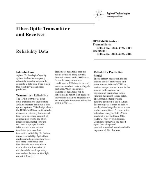
Fiber-Optic Transmitter and ReceiverReliability Data IntroductionAgilent Technologies’ quality system includes an ongoing reliability monitor program to generate a data base from which this reliability data sheet is published.Transmitter Reliability The HFBR-0400 Series fiberoptic transmitters incorporate AlGaAs emitters and double lens optical systems. This design allows the HFBR-14XX transmitters to be driven at a relatively low current level for a specified amount of coupled power into the fiber. Because transmitter forward currents are proportional to failure rates, a low current translates into excellent transmitter reliability. To further improve reliability, Agilent has implemented a proprietary wafer screening technology that identifies dislocations whichcan lead to the formation of darkline defects (the primary mechanism for transmitter light output failures).HFBR-0400 SeriesTransmitters:HFBR-1402, -1412, -1404, -1414Receivers:HFBR-2402, -2412, -2406, -2416 Transmtter reliability data hasbeen calculated using 100 mAforward current and a 100% dutyfactor. In many actual useconditions, a 50% duty factor andlower forward currents are highlyprobable. When this is true,transmitter reliability will besubstantially better. The degree ofimprovement can be projected byexamining the footnotes below theHFBR-14XX data.Reliability PredictionModelThe reliability prediction modelused to project failure rate andmean time to failure (MTTF) atvarious temperatures shown in thesecond table assumes anexponential cumulative failurefunction (constant failure rate).The Arrhenius temperaturederating equation is used. AgilentTechnologies assumes no failuremechanism change between stressand use conditions. A conservativeactivation energy of 0.43 eV wasused and is derived from MIL-HDBD-217 for hybrid devices.Confidence intervals are basedupon the chi-squaredprediction method associated withexponential distributions.Fiber-Optic TransmitterReliability Data HFBR-1402HFBR-1412HFBR-1404HFBR-1414High Temperature Operating Life TestA. Demonstrated PerformanceTest Equivalent Test Condition Samples Device Hours Failures HTOL T A = 85°C, I F = 100 mA880 units879,5003B. Failure CriteriaFailure has occurred when the unitfails catastrophically, or when thelight output power decreases 3 dB.Point Typical PerformancePerformance [1]in Time [2]in Time(90% Confidence) Ambient Junction MTTF [1]FITs [3]MTTF [2]FITs [3] Temperature (°C)Temperature (°C)(hours)(/109 Hours)(hours)(/109 Hours) 85100293,0003411131,00075968095352,0002844158,00063347590424,0002360190,00052557085514,0001947231,00043376580626,0001598281,00035606075766,0001305344,00029055570945,0001059424,000235750651,172,000854526,000190145601,462,000684657,000152340551,838,000544825,000121235502,326,0004301,044,00095830452,965,0003371,331,00075125403,810,0002631,711,000585C. Failure Rate Prediction for Random Failures (I F @ 100 mA, 100% duty cycle)Notes:1. The point MTTF (representing an esti-mate of the mean point MTTF) is the total device hours divided by either the number performance that is expected from 90% ofall samples. This confidence interval isbased on the statistics of the distribution offailure rates prior to the onset of wear out.Refer to MIL-STD-690 for details of thismethodology.Fiber-Optic Link ReceiverReliability DataHFBR-2402HFBR-2412High Temperature Operating Life TestA. Demonstrated PerformanceTest Equivalent Test Condition Samples Device Hours Failures HTOL T A = 85°C, V CC = 5.25 V3,9602,370,0001B. Failure CriteriaFailure has occurred when the unitfails catastrophically. One devicefailed to switch logic states.Point Typical PerformancePerformance [1]in Time [2]in Time(90% Confidence) Ambient Junction MTTF [1]FITs [3]MTTF [2]FITs [3] Temperature (°C)Temperature (°C)(hours)(/109 Hours)(hours)(/109 Hours) 851002,370,000421609,0001,64080952,880,000346742,0001,34075903,530,000282909,0001,09070854,350,0002291,120,00089265805,400,0001841,390,00071960756,740,0001481,730,00057655708,480,0001172,180,000458506510,700,000932,750,000362456013,600,000733,510,000284405517,500,000564,520,000221355022,700,000435,850,000170304529,700,000337,650,000130254039,200,0002510,000,00099C. Failure Rate Prediction, Receiver (V CC = 5.25 V)Notes:1. The point MTTF (representing an esti-mate of the mean point MTTF) is the total device hours divided by either the number performance that is expected from 90% ofall samples. This confidence interval isuseful life failures. Refer to MIL-STD-690 fordetails of this methodology.Fiber-Optic Link ReceiverReliability DataHFBR-2406HFBR-2416High Temperature Operating Life TestA. Demonstrated PerformanceTest Equivalent Test Condition Samples Device Hours Failures HTOL T A = 85°C, V CC = 5.25 V2,2502,250,0000B. Failure CriteriaFailure has occurred when the unitfails catastrophically.Point Typical PerformancePerformance [1]in Time [2]in Time(90% Confidence) Ambient Junction MTTF [1]FITs [3]MTTF [2]FITs [3] Temperature (°C)Temperature (°C)(hours)(/109 Hours)(hours)(/109 Hours) 851002,250,000444977,164102380952,698,5163711,171,95385375903,252,6873071,412,62770870853,941,1732541,711,63358465804,801,4322082,085,24048060755,882,7441702,554,84939155707,250,3821383,148,80831850658,991,4071113,904,927256456011,222,799894,874,010205405514,102,949716,124,846163355017,848,023567,751,315129304522,755,516449,882,616101254029,238,4093412,698,10779C. Failure Rate Prediction, Receiver (V CC = 5.25 V)Notes:1. The point MTTF (representing an esti-mate of the mean point MTTF) is the total device hours divided by either the number performance that is expected from 90% ofall samples. This confidence interval isuseful life failures. Refer to MIL-STD-690 fordetails of this methodology.HFBR-0400 Mechanical and Environmental Test Data [1]MIL-STD-883D Units Total Test Name Reference Test Conditions Tested Failed Temperature Cycle1010500 cycles from -55 to +125°C, 15 minutes20201at extremes, 5 minutes transfer. [1]HFBR-1414500 cycles from -55 to +125°C, 15 minutes20900at extremes, 5 minutes transfer.[1]HFBR-2416 85/85T A = 85°C, 85% relative humidity,21407No bias, duration = 1,000 hours. [1]HFBR-1414T A = 85°C, 85% relative humidity,22206V CC = 5 volts, Duration = 1,000 hours[1]HFBR-2416 High Temperature1008T A = 125°C800 Storage Condition B1000 hoursResistance to2015Three 1 minute immersions.200 Solvents Brush after solvent immersion.Chemical Resistance— 5 minutes in Acetone, Methanol, Freon TF200and Boiling WaterVibration Variable 2007,20 G min., 20 to 2000 Hz.200 Frequency Condition B4, 4 minute cycles each X, Y, and Z.Thermal Shock1011-55°C to +125°C, 15 cycles600Condition B 5 min. dwell / 10 sec. transferMechanical Shock2002, 5 blows each X1, X2, Y1, Y2, Z1, Z2600Condition B1500 G, 0.5 msec. pulse.Port Wear Test [2]T A = 25°C500 connectorings200Less than 1 dBm variationConnector Side T A = 25°C 1 kg side load100 Load [3]Less than 1 dBm variationPort Strength [4]T A = 25°C 6 kg-cm (5.21 inch-lbs), no port damage100 Seal-Dye Penetrant101445 psi, 10 hours200 (Zyglo)Condition D No Leakage into microelectronic cavitySolderability2003245°C300 ESD Method 3015Human body model @ 10,000 V50HFBR-1414Human body model @ 2,000 V50HFBR-2402Human body model @ 1000 V50HFBR-2416Notes: See following page.Notes:1. Devices were preconditioned with 10 second, 260°C solder dip and 20 cycles, -40°C to 85°C, temperature cycle.2. Coupled power measurements were maximized before and after stress in determining the 1 dBm variation for SMA HFBR-0400 products. HFBR-0400 ST products do not require this due to the improved coupling design.3. The Connector Side Load test was only applied to HFBR-0400 SMA products. The Connector Side Load testing required that the housing be held so to prevent the leads from yielding. The load was applied through a SMA connectored fiber optic cable, perpendicular to the port. The product family is designed to limit cable and ferrule damage due to cable loading. The support and active leads should yield before damage to the cable or connector occurs. If extreme mechanical abuse of the cable/ connector is anticipated please contact Agilent’s Application Department for suggestions about mechanical strain relief. Due to the spring loaded feature of the ST connector, HFBR-0400 ST products will experience 1 dBm coupled power variation at a side load of less than 1 kg.4. The Port Strength test was designed to gauge the concerns with hand tightening the connector to the fiber optic port. The limit is set to alevel beyond most reasonable hand fastening loading.5. Package tests are defined as stresses that indicate the environmental strength of the package. Units tested indicate the total number of devices taken from the product family. While not all part numbers have been subjected to each stress, worst case products have been included.。
气井积液预测研究进展张烈辉1 罗程程1 刘永辉1 赵玉龙1 谢春雨2 张琦3 艾先婷11.“油气藏地质及开发工程”国家重点实验室·西南石油大学2.中国石油西南油气田公司安全环保与技术监督研究院3.中国石油西南油气田公司川东北气矿摘 要 准确预测气井积液时间并及时采取排水采气工艺措施,对于维持低产气井稳定生产至关重要。
为此,基于对国内外气井积液预测方法及积液气井数值模拟方法的广泛调研和总结,综合分析了目前解释气井积液的液滴反转模型、液膜反转模型和气井稳定性分析方法,阐述了积液气井瞬态数值模拟的研究进展。
研究结果表明:①不同积液预测模型计算值之间及不同类型气藏气井携液临界气量之间存在着巨大的偏差,引起气井积液的机理不仅仅由单一液体反转现象造成,而是地层与井筒共同作用的结果;②液体反转理论在解释气井出现动液面上有悖于气液两相管流的基本规律,气井动液面的产生与气井受到瞬态扰动相关。
在上述研究的基础上,指出了气井积液机理研究的发展方向:结合地层数值模拟,建立合理井筒压力波动模型并将其考虑为内边界条件,开展地层—井筒耦合实验及理论研究,揭示不同类型气藏积液的控制机理并建立相应积液预测模型,以期为气井排水采气工艺设计提供理论依据和技术支撑。
关键词 气井积液 液滴反转模型 液膜反转模型 气井稳定性分析 地层—井筒耦合 数值模拟 实验室试验DOI: 10.3787/j.issn.1000-0976.2019.01.006Research progress in liquid loading prediction of gas wells Zhang Liehui1, Luo Chengcheng1, Liu Yonghui1, Zhao Yulong1, Xie Chunyu2, Zhang Qi3 & Ai Xianting1 (1. State Key Laboratory for Oil & Gas Reservoir Geology and Exploitation//Southwest Petroleum University, Cheng-du, Sichuan 610500, China; 2. HSE and Technical Supervision Research Institute, PetroChina Southwest Oil & Gas-field Company, Chengdu, Sichuan 610041, China; 3. Northeast Sichuan Division, PetroChina Southwest Oil & Gasfield Company, Dazhou, Sichuan 635000, China)NATUR. GAS IND. VOLUME 39, ISSUE 1, pp.57-63, 1/25/2019. (ISSN 1000-0976; In Chinese)Abstract: In order to maintain the stable production of low-yield gas wells, it is crucial to accurately predict the onset of liquid loading and take the technical measures of drainage gas recovery in time. In this paper, domestic and foreign prediction and numerical simulation methods used for liquid loading in gas wells were extensively investigated and summarized. Then, the methods which are currently used to interpret the liquid loading in gas wells were analyzed comprehensively, including liquid-droplet reversal model, liquid-film reversal model and gas-well stability analysis method. Finally, the research progress in the transient numerical simulation of gas wells with liquid loading was illustrated. And the following research results were obtained. First, the calculation results of different liquid-loading predic-tion models and the critical liquid-carrying gas rates of gas wells in different gas reservoirs are greatly different. The mechanism of liquid loading in gas wells is not only caused by single liquid reversal phenomenon, but also the joint effect of formation and wellbore . Second, in interpreting the dynamic liquid level of gas well, the liquid reversal theory is contrary to the basic rule of gas–liquid two-phase pipe flow. The dynamic liquid level of gas well is related to the transient disturbance of gas well. Based on above studies, the development direction of the studies on the mechanism of liquid loading in gas wells was pointed out as follows. Establish a reasonable wellbore pressure fluctuation model on the basis of the numerical reservoir simulation, and take it as the inner boundary condition. Carry out ex-perimental and theoretical studies on formation–wellbore coupling. Reveal the control mechanisms of liquid loading in different types of reservoirs, and establish liquid-loading prediction model correspondingly so as to provide theoretical basis and technical support for the design of drainage gas recovery of gas wells.Keywords: Liquid loading of gas wells; Liquid-droplet reversal model; Liquid-film reversal model; Stability analysis on gas well; For-mation–wellbore coupling; Numerical simulation; Laboratory experiment基金项目:国家自然科学基金重大项目“致密气藏储层干化、提高气体渗流能力的基础研究”(编号:51534006)、国家自然科学基金项目“基于边界元法的页岩气藏缝网多段压裂水平井不稳定渗流理论研究”(编号:51704247)、国家自然科学基金项目“耦合压裂缝网扩展机制的页岩气藏动态模拟研究”(编号:51874251)。
Fiber-Optic Transmitter and ReceiverReliability Data IntroductionAgilent Technologies’ quality system includes an ongoing reliability monitor program to generate a data base from which this reliability data sheet is published.Transmitter Reliability The HFBR-0400 Series fiberoptic transmitters incorporate AlGaAs emitters and double lens optical systems. This design allows the HFBR-14XX transmitters to be driven at a relatively low current level for a specified amount of coupled power into the fiber. Because transmitter forward currents are proportional to failure rates, a low current translates into excellent transmitter reliability. To further improve reliability, Agilent has implemented a proprietary wafer screening technology that identifies dislocations whichcan lead to the formation of darkline defects (the primary mechanism for transmitter light output failures).HFBR-0400 SeriesTransmitters:HFBR-1402, -1412, -1404, -1414Receivers:HFBR-2402, -2412, -2406, -2416 Transmtter reliability data hasbeen calculated using 100 mAforward current and a 100% dutyfactor. In many actual useconditions, a 50% duty factor andlower forward currents are highlyprobable. When this is true,transmitter reliability will besubstantially better. The degree ofimprovement can be projected byexamining the footnotes below theHFBR-14XX data.Reliability PredictionModelThe reliability prediction modelused to project failure rate andmean time to failure (MTTF) atvarious temperatures shown in thesecond table assumes anexponential cumulative failurefunction (constant failure rate).The Arrhenius temperaturederating equation is used. AgilentTechnologies assumes no failuremechanism change between stressand use conditions. A conservativeactivation energy of 0.43 eV wasused and is derived from MIL-HDBD-217 for hybrid devices.Confidence intervals are basedupon the chi-squaredprediction method associated withexponential distributions.Fiber-Optic TransmitterReliability Data HFBR-1402HFBR-1412HFBR-1404HFBR-1414High Temperature Operating Life TestA. Demonstrated PerformanceTest Equivalent Test Condition Samples Device Hours Failures HTOL T A = 85°C, I F = 100 mA880 units879,5003B. Failure CriteriaFailure has occurred when the unitfails catastrophically, or when thelight output power decreases 3 dB.Point Typical PerformancePerformance [1]in Time [2]in Time(90% Confidence) Ambient Junction MTTF [1]FITs [3]MTTF [2]FITs [3] Temperature (°C)Temperature (°C)(hours)(/109 Hours)(hours)(/109 Hours) 85100293,0003411131,00075968095352,0002844158,00063347590424,0002360190,00052557085514,0001947231,00043376580626,0001598281,00035606075766,0001305344,00029055570945,0001059424,000235750651,172,000854526,000190145601,462,000684657,000152340551,838,000544825,000121235502,326,0004301,044,00095830452,965,0003371,331,00075125403,810,0002631,711,000585C. Failure Rate Prediction for Random Failures (I F @ 100 mA, 100% duty cycle)Notes:1. The point MTTF (representing an esti-mate of the mean point MTTF) is the total device hours divided by either the number performance that is expected from 90% ofall samples. This confidence interval isbased on the statistics of the distribution offailure rates prior to the onset of wear out.Refer to MIL-STD-690 for details of thismethodology.Fiber-Optic Link ReceiverReliability DataHFBR-2402HFBR-2412High Temperature Operating Life TestA. Demonstrated PerformanceTest Equivalent Test Condition Samples Device Hours Failures HTOL T A = 85°C, V CC = 5.25 V3,9602,370,0001B. Failure CriteriaFailure has occurred when the unitfails catastrophically. One devicefailed to switch logic states.Point Typical PerformancePerformance [1]in Time [2]in Time(90% Confidence) Ambient Junction MTTF [1]FITs [3]MTTF [2]FITs [3] Temperature (°C)Temperature (°C)(hours)(/109 Hours)(hours)(/109 Hours) 851002,370,000421609,0001,64080952,880,000346742,0001,34075903,530,000282909,0001,09070854,350,0002291,120,00089265805,400,0001841,390,00071960756,740,0001481,730,00057655708,480,0001172,180,000458506510,700,000932,750,000362456013,600,000733,510,000284405517,500,000564,520,000221355022,700,000435,850,000170304529,700,000337,650,000130254039,200,0002510,000,00099C. Failure Rate Prediction, Receiver (V CC = 5.25 V)Notes:1. The point MTTF (representing an esti-mate of the mean point MTTF) is the total device hours divided by either the number performance that is expected from 90% ofall samples. This confidence interval isuseful life failures. Refer to MIL-STD-690 fordetails of this methodology.Fiber-Optic Link ReceiverReliability DataHFBR-2406HFBR-2416High Temperature Operating Life TestA. Demonstrated PerformanceTest Equivalent Test Condition Samples Device Hours Failures HTOL T A = 85°C, V CC = 5.25 V2,2502,250,0000B. Failure CriteriaFailure has occurred when the unitfails catastrophically.Point Typical PerformancePerformance [1]in Time [2]in Time(90% Confidence) Ambient Junction MTTF [1]FITs [3]MTTF [2]FITs [3] Temperature (°C)Temperature (°C)(hours)(/109 Hours)(hours)(/109 Hours) 851002,250,000444977,164102380952,698,5163711,171,95385375903,252,6873071,412,62770870853,941,1732541,711,63358465804,801,4322082,085,24048060755,882,7441702,554,84939155707,250,3821383,148,80831850658,991,4071113,904,927256456011,222,799894,874,010205405514,102,949716,124,846163355017,848,023567,751,315129304522,755,516449,882,616101254029,238,4093412,698,10779C. Failure Rate Prediction, Receiver (V CC = 5.25 V)Notes:1. The point MTTF (representing an esti-mate of the mean point MTTF) is the total device hours divided by either the number performance that is expected from 90% ofall samples. This confidence interval isuseful life failures. Refer to MIL-STD-690 fordetails of this methodology.HFBR-0400 Mechanical and Environmental Test Data [1]MIL-STD-883D Units Total Test Name Reference Test Conditions Tested Failed Temperature Cycle1010500 cycles from -55 to +125°C, 15 minutes20201at extremes, 5 minutes transfer. [1]HFBR-1414500 cycles from -55 to +125°C, 15 minutes20900at extremes, 5 minutes transfer.[1]HFBR-2416 85/85T A = 85°C, 85% relative humidity,21407No bias, duration = 1,000 hours. [1]HFBR-1414T A = 85°C, 85% relative humidity,22206V CC = 5 volts, Duration = 1,000 hours[1]HFBR-2416 High Temperature1008T A = 125°C800 Storage Condition B1000 hoursResistance to2015Three 1 minute immersions.200 Solvents Brush after solvent immersion.Chemical Resistance— 5 minutes in Acetone, Methanol, Freon TF200and Boiling WaterVibration Variable 2007,20 G min., 20 to 2000 Hz.200 Frequency Condition B4, 4 minute cycles each X, Y, and Z.Thermal Shock1011-55°C to +125°C, 15 cycles600Condition B 5 min. dwell / 10 sec. transferMechanical Shock2002, 5 blows each X1, X2, Y1, Y2, Z1, Z2600Condition B1500 G, 0.5 msec. pulse.Port Wear Test [2]T A = 25°C500 connectorings200Less than 1 dBm variationConnector Side T A = 25°C 1 kg side load100 Load [3]Less than 1 dBm variationPort Strength [4]T A = 25°C 6 kg-cm (5.21 inch-lbs), no port damage100 Seal-Dye Penetrant101445 psi, 10 hours200 (Zyglo)Condition D No Leakage into microelectronic cavitySolderability2003245°C300 ESD Method 3015Human body model @ 10,000 V50HFBR-1414Human body model @ 2,000 V50HFBR-2402Human body model @ 1000 V50HFBR-2416Notes: See following page.Notes:1. Devices were preconditioned with 10 second, 260°C solder dip and 20 cycles, -40°C to 85°C, temperature cycle.2. Coupled power measurements were maximized before and after stress in determining the 1 dBm variation for SMA HFBR-0400 products. HFBR-0400 ST products do not require this due to the improved coupling design.3. The Connector Side Load test was only applied to HFBR-0400 SMA products. The Connector Side Load testing required that the housing be held so to prevent the leads from yielding. The load was applied through a SMA connectored fiber optic cable, perpendicular to the port. The product family is designed to limit cable and ferrule damage due to cable loading. The support and active leads should yield before damage to the cable or connector occurs. If extreme mechanical abuse of the cable/ connector is anticipated please contact Agilent’s Application Department for suggestions about mechanical strain relief. Due to the spring loaded feature of the ST connector, HFBR-0400 ST products will experience 1 dBm coupled power variation at a side load of less than 1 kg.4. The Port Strength test was designed to gauge the concerns with hand tightening the connector to the fiber optic port. The limit is set to alevel beyond most reasonable hand fastening loading.5. Package tests are defined as stresses that indicate the environmental strength of the package. Units tested indicate the total number of devices taken from the product family. While not all part numbers have been subjected to each stress, worst case products have been included.。
6、Tensile strength and abutment relaxation as failure control mechanisms in underground excavationsAbstract:Classical assessment of instability potential in underground excavations are normally based on yield and rupture criteria for stress driven failure and on limit equilibrium analysis of structurally controlled failure. While it is true that ultimate failure and falls of ground can be an eventual consequence of stress fracturing and unfavourable structure within the rock mass, the timing of such failure is often controlled by the presence of residual tensile capacity, in the form of rock bridges separating joint segments and fractures and by the mechanisms of clamping and relaxation. Using crack and rock-bridge analogues in conjunction with an updated voussoir beam model, this paper explores the in¯uence of residual tensile strength and boundary parallel relaxation on the failure process. The impact on support design is also examined. In underground hard rock mines with complex geometries and interacting openings, relaxation is identi®ed as a key controlling factor in groundfall occurrence. Empirical stability assessment techniques for underground tunnels and for mining stopes are updated to account for relaxation.IntroductionStability assessment of underground excavations is classically divided into two procedural domains. These two domains are based on a distinction between struc-turally controlled and stress driven modes of instabil-ity. It is the premise of this paper, however, that in non-squeezing and non-bursting ground, structure and stress serve merely as ground conditioning mechan-isms. Gravity loading is ultimately responsible for large scale groundfalls or for signi®cant loading of support. When the rock mass jointing is non-persist-ent, the rock bridges contribute to the stability of an excavation through the rock mass residual tensile strength or load bearing capacity. The failure to con-sider the rock mass self-supporting capacity and the e.ects of abutment con®nement or abutment relax-ation can lead to erroneous predictions of failure or ofsupport load.Gravity induced groundfalls are common occur-rences in underground excavations of all depths. Numerous techniques can be applied to assess the po-tential for such groundfalls provided that an appropri-ate failure mode is assumed. Typical failure modes which can be analyzed include wedge fallout, slab or plug failure, gravity driven caving and beam failure.Models taking these failure modes into account are generally usually utilized for associated with stability assessments in low stress or near surface excavations. The underlying assumption of most of these models is that through-going joints or discontinuities are fully persistent and that stability is controlled by structural geometry and by friction (with or without dilation). The inherent tensile or cohesive strength of moderately jointed rock masses is often assumed to be negligible in these models.Alternatively, for excavations at depth or for shal-lower excavations in weaker rockmasses, linear elastic stress analysis can be used to determine the location and extent of problematic stress concentrations around the openings. Failure criteria such as Mohr±Coulomb and Hoek±Brown [1, 2] based on combined cohesive and frictional strength components can be applied suc- cessfully if the rock mass yields with signi®cant plastic deformation. These criteria, however, meet with only limited success [3, 4] for failure prediction around exca-vations in hard rock environments due to their insensi-tivity to low con®nement behaviour. In brittle ground, it has been shown [5±9] that under low con®nement (such as that which exists adjacent to an opening), tan-gential compressive stress above a de®ned threshold in-itiates and propagates boundary parallel cracks or fractures.Such rock mass damage can be responsible for observed seismicity [9] and stress redistribution [10] and was found to correlate well with a constant critical deviator criteria for damage initiation, both in intact and in moderately jointed rock [9, 11]. This initial cracking or fracturing is generally parallel to the exca-vation surface and therefore parallel to the major com-pressive stress. This crack damage is strain dependant and may be exacerbated by preferential de¯ection and dilation into an opening and by existing planes of weakness such as foliation or meta-bedding resulting eventually in moderately persistent planar laminations in otherwise massive or moderately jointed rock(Fig. 1).Nevertheless, a prediction of rock mass stress in excess of yield limits, based on elastic models, does not inevitably correspond to actual catastrophic failure of the underground opening. This is fortunate given the depths encountered in modern mining, where much of the ground above mining openings has reached a damage or yield stress threshold at some point in the mining sequence and yet, with the exception of highly stressed ground experiencing rockbursting, shearing or stress buckling, generally remains in place in the short term. This is due to the rock mass' residual tensile load bearing capacity normal to the excavation bound-ary and due to arching to the abutments.Paradoxically, ultimate failure of this damaged ground is often induced by changes in mine geometry which reduce [12±16] rather than increase the stresses across the back or walls as might have been the case in Fig. 1. It is the premise of this paper that the key to this discrepancy between modeled or predicted failure and the actual observed occurrence of failure in under-ground excavations in hard rock is due to the domi-nance of the rock mass's tensile load bearing capacity.However, if combined with abutment relaxation, thein¯uence of gravity can exceed the tensile load bearing capacity of naturally jointed or stress fractured rock masses leading to the type of failure illustrated in Fig. 1. This paper will not attempt to explain the gen-esis of natural fractures and associated rock bridges, Fi nor will it examine the mechanics of formation for boundary parallel stress cracks. The foregoing discus-sion assumes that such damage is omni-present in underground excavations and explains the possible impact on ultimate stability.In this paper we will discuss the nature of residual tensile capacity in jointed or fractured rock masses comparing its capacity to that of economical engin-eered support systems. The e.ect of abutment relax-ation on rock wedge and blocky slabstability is demonstrated. Di.erent mining scenarios are described which may lead to destabilizing relaxation. The vous-soir arch analogue is used to further demonstrate the importance of boundary normal tensile capacity and abutment relaxation. The voussoir analogue is then calibrated to correspond with empirical stability guide-lines for rock mass stability. The e.ect of relaxation is further demonstrated in this context. Conclusions:The presence of geometrically unfavourable jointing or rock mass damage due to elastic predictions of overstress does not, in itself, dictate that failure will take place. Neglecting the possibility of dynamic pro-cesses such as compression-induced buckling, degra-dation of residual tensile strength or abutment relaxation is often required before failure can take place.Rock masses are inherently discontinuous due to natural jointing or induced fracturing. It is often erro-neous to assume that this fracturing is fully persistent. In massive to moderately jointed rock residual tensile load bearing strength arising from incomplete fractur-ing or from rock bridges separating non-persistent joining is a key factor in the control of ultimate grav-ity driven failure of jointed or stress damaged ground.Very little rock bridge cross-sectional area (less than 1% in most cases) is required in hard rocks to replace most arti®cial support systems. The time dependency of this residual tensile strength due to stress corrosion and atmospherically induced crack growth controls stand-up time and mandates the use of support sys-tems in most underground excavations. Sti. Support such as grouted rebar can suppress dilation strains and preserve some of this internal tensile strength, contri-buting to a reduction in both short term and long term support requirements. There is great economic advantage to selecting, as part of a multi-component support system, sti. elements which can preserve the rock mass internal tensile capacity. Careful blast damage control is also an obvious advantage. Early installation of shotcrete or spray-on linings in a dry rock mass at depth can reduce the impact of atmos-pheric e.ects and time dependent stress corrosion on stressed rock bridges.Boundary parallel relaxation is another dominating factor in delayed mining induced failure of spans in underground excavations, signi®cantly shifting conven-tional no-support limits so that smaller spans or ad-ditional support are required. Dangerous abutment relaxation can occur even at depth, driven by un-favourable stress ratios, complex mine geometries, abutment damage, intersection development and undercutting. Abutment relaxation increases support demands by reducing the natural ability of the rock mass to transfer loads to the abutments through arch-ing. In addition, boundary normal stress relaxation has been shown to reduce the capacity of frictional support systems, exacerbating ground control pro-blems.A voussoir beam analogue was used to illustrate the importance of internal boundary normal tensile strength and of abutment relaxation in controlling the stability of spans in laminated rock masses. The results of the voussoir simulation were used to modify empiri-cal stope design limits, accounting for abutment relax-ation. A few millimetres of hangingwall or back abutment relaxation can signi®cantly shift the no-sup-port limit, inducing failure in previously stable spans. It is therefore important to sequence development and stope extraction properly to minimize this relaxation and tominimize the size of secondary stopes. The creation of high relaxation geometries, such as hanging-wall undercutting, must be avoided.6.在地下挖掘机制拉伸强度和桥墩松弛的失效控制摘要:地下洞室群的不稳定可能是典型的评估通常基于屈服应力驱动的失败和破裂准则和极限平衡分析构造控制失败。
石油英语词汇(F1)石油英语词汇(F1)石油英语词汇(F1)f ahd 全速前进f ast 全速后退f number 光圈数f stop f光阑f test f 检验f 保险丝f 灯丝f 地层因素f 法拉f 法拉第常数f 范氏摩擦系数f 飞母托f 氟f 光圈数f 函数f 华氏度数f 力f 滤器;滤波器f 滤液;泥浆滤液f 频率f 组f-coal 丝炭为主的显微质点f-k analysis f-k分析f-k filter f-k滤波器f-k migration f-k 偏移f-k space 频率-波数空间f-k spectra f-k 谱f-k transform f-k 变换f-k velocity filtering f-k 速度滤波f. 二月f. 满f. 面宽;齿宽f. 频率计f.b. 运货单f.c. 期货交易合同f.c. 英尺-烛光f.c.b.p. 可付外币f.c.c. 面心立方f.d. 加工和钻孔f.d. 强力鼓风f.e. 例如f.e. 外汇期货f.f. 固定焦点f.fw. 管件与管件焊接f.h.p 摩擦马力f.l.t 地层压漏试验f.l.t 满载转矩f.o. 到港价格f.o. 确盘f.o. 准备出发f.p. 法国专利f.p. 纸绝缘薄膜电容器fa 工厂自动化fa 故障分析fa 急救fa 英寻fa 脂肪酸faa 游离氨基酸faas 火焰原子吸收光谱法fab 弧前盆地fab 急救箱faber viscosimeter 法伯尔粘度计fabian system 冲击钻进法fabric analysis 组构分析fabric cartridge filter 筒式纤维织网过滤器fabric filler 织物填料fabric screen 纤维滤网fabric selective 选择性组构fabric selectivity 组构选择性fabric tank 软桶fabric 岩组fabric-axes 组构轴fabric-jacket foamglass 外裹纤维布的泡沫玻璃fabricant 制造者fabricate 制造fabricated construction 装配式施工fabricated language 人造语言fabricated mast 装配式轻便井架fabricated section 安装件fabricated sheave 组装滑轮fabricated valve 高压锻钢阀门fabricating cost 造价fabricating yard 施工现场fabrication crew 制造小组fabrication drawing 施工图fabrication phase 制造阶段fabrication weldability 工艺可焊性fabrication 制造fabricator 制造者fabriform 焊制结构fabroil 夹布胶木fac 传真facade 正面;表面face angle 面角钢face bar 面材face contact 工作接点face direction 面方向face guard 防护面罩face hardening 表面硬化face lathe 端面车床face left 盘左face line of teeth 齿峰线face machined flat 磨平面face mask 面罩face of gear 齿轮面face of pulley 滑轮侧板face of the channel 岩层孔道面face of the wellbore 井壁face of tool 切削面face of tooth 齿面face of weld 焊接面face of wheel 轮面face off 研磨端面face plugging 层面堵塞face right 盘右face runout 端面跳动face seal 面密封face shield 护面罩face shovel 正铲挖土机;正铲face value of the stock 股票面值face value 票面价值face velocity 沿面流速face work 抹面工作face yarn 面纱face 层面face-around 改变方向face-centered cubic lattice 面心立方晶格face-to-face 面对面;弯头接口面到面尺寸facepiece 面罩faceplate 面板facer 意外的障碍;铣刀盘facet 小面facetted boulder 磨面巨砾facetted pebble 棱石facial difference 相差异facial 相的;面的facient 乘数facieology 岩相学;相分析facies analysis 相分析facies association 相组合facies belt 相带facies change trap 相变圈闭facies change 相变facies cycle 相旋回facies data-base 岩相数据库facies diagram 相图facies evolution 相演变facies fauna 指相动物群facies fossil 指相化石facies group 相组facies identification 岩相识别facies map 相图facies model 相模式facies pattern 相型facies principle 相原理facies relationship diagram 相关系图facies relationship 相关系facies sequence analysis 相序列分析facies sequence 相序facies strike 相走向facies tract 相带facies trap 岩相圈闭facies triangle 相三角图facies type 相类型facies 相facies-controlled 相控制的facilitate 促进facilities 设施facility destruction 设施损坏facility of payment clause 支付协定条款facility programs 侦查程序facility 设备facing alloy 敷焊的硬合金facing machine 坡口机;刨床facing 变新的方向;饰面;涂料;端面车削faciolog 测井相解释程序名faciostratotype 相地层典型剖面facs 设备facsimile channel 传真频道facsimile chart 传真图facsimile communication 传真通信facsimile log 复制曲线facsimile paper 传真感光纸facsimile radio 无线电传真facsimile receiver 传真接收装置facsimile record 传真记录facsimile recorder 传真机facsimile seismograph 能直接在传真感光纸上记录的地震仪facsimile service 传真通信facsimile signal 传真信号facsimile telegram 传真电报facsimile telegraph 无线电传真facsimile transmission 传真发送facsimile unit 传真装置facsimile 传真facsimiles of authorized signatures 有权签字的样本;授权签字的印鉴fact 全自动编译技术fact 事实factitious 人造的;假冒的factor analysis 因子分析factor loading 因子载荷factor model 因子模型factor of assurance 保险系数factor of correction 校正系数factor of merit 优质因数factor of normalization 标准化因子factor of over capacity 过载系数factor of porosity 孔隙度factor of proportionality 比例因子factor of safety against cracking 抗裂安全系数factor of safety 安全系数factor of saturation 饱和度factor out 析出因数factor pattern 因子型式factor score 因子得分factor structure 因子结构factor variance diagram 因子方差图factor weight 因数重量;因数法码factor 系数factorability 可分因数性factorage 代理业;手续费factorial analysis 因子分析factorial design experiment 因子设计试验factorial design 因子设计factorial discriminant anlalysis 因子判别式分析factorial polynomial 阶乘多项式factorial series 阶乘级数factorial 因子的factoring 因子分解factoriol notation 阶乘记号factorization method 因子分解法factorization of polynomial 多项式因子分解factorization 因子分解factory assembly 工厂装配factory automation 工厂自动化factory cost 工厂成本factory for prefabrication 预制厂factory formula 生产配方factory inspection 出厂检验factory pipe bend 预制弯头factory preassembly 工厂预装配factory price 出厂价格factory runs 大量生产factory ship 加工船factory test 工厂试验factory work 工厂作业factory 工厂factory-calibrated 工厂校准的factory-made component 工厂预制构件factual survey 实情调查facula 光斑faculae facula 的复数facultative aerobe 兼性好氧菌facultative anaerobe 兼性厌氧菌facultative bacteria 兼性细菌facultative lagoon 兼性塘facultative thermophils 兼性嗜热菌faculty 技能fad 浮点加fade in 渐显fade out 渐隐fade resistance 抗褪色性fade 褪色;衰落fader 音量控制器fading 衰落fae. 远东faes 火焰原子发射光谱法fafs 火焰原子荧光光谱法fag 疲劳;辛苦地工作;使疲劳;磨损fagot 成束熟铁块faguspollenites 山毛榉粉属faguus 山毛榉属fahrenheit temperature scale 华氏温标fahrenheit temperature 华氏温度fahrenheit thermometer 华氏温度计fahrenheit 华氏;华氏温度计的fai 通风口faience 瓷器fail in bending 弯曲破坏fail in compression 压缩破坏fail in shear 剪切破坏fail in tension 拉伸破坏fail open 应急开放fail safe 故障防护;故障自动保险的fail to 未能fail 错误fail-closed 出故障时自动关闭的fail-safe close valve 故障自动关闭阀fail-safe control 故障控制fail-safe device 失效安全保障装置fail-safe lockout device 故障自动闭锁装置fail-safe open valve 故障自动开放阀fail-safety 系统可靠性fail-soft 工作可靠但性能下降fail-test 可靠性试验failed arm 断裂滑块failed rift 衰退裂谷failed test sample 不合格样品failing load 破坏载荷failing stress 破坏应力failing 缺点;如果没有…时;失败的failure analysis 故障分析failure detonation 拒爆failure due to fatigue 疲劳破坏failure exception mode 失效异常方式failure mechanism 破坏机理failure message 故障信息failure mode 故障种类failure of fuel 燃料系故障failure of oil feed 供油中断failure of performance 未履行合同failure of the current 电流的故障failure plot 腐蚀损坏剖面failure point 破裂〔失效failure prediction 故障预测failure pressure 破裂压力failure rate 故障率failure strain 破坏变形failure test 破坏试验failure warning 故障警报failure zone 断损区域failure 失败failure-free operation 无故障运行failure-rate average function 失效率平均函数failure-safe system 故障自动排除系统faint negative 浅底片faint 微弱的faintly acid 弱酸的faintly alkaline reaction 弱碱性反应fair average quality 中等质量fair current 顺流fair curve 修正曲线fair dealing 公平交易fair drafting 清绘fair game 公平游戏fair price 公平价格fair tide 顺潮流fair trade 公平交易fair water fin 导流板fair water 导流罩;整流器fair wind 顺风fair 市集fair-weather runoff 基本径流fairing 减阻装置fairlead 引线孔fairleader 导索环fairness 公正性fairth 信任fairway 航道fairy stone 十字石faithful 忠实的;正确的;可靠的fake 砂质页岩fal 流量分析测井falcodus 镰齿牙形石属falcon engine rust test 法尔康发动机锈蚀试验falex friction machine 法列克司摩擦试验机fall head 落差fall in 坍塌fall of ground 地层陷落fall of potential 电位降fall out of step 失步fall peneplain 准平原风化带fall rate 降落速率fall time 衰变时间fall velocity 沉降速度fall 通索fall-of-potential method 电位降法fall-off curve 压降曲线fall-off test 压降试井fall-off 衰减fall-out radioactive materials 放射性沉积物fallacy 谬误fallaway 分开fallback 降落原地;后退fallen-in 坍塌falling ball viscosimeter 落球粘度计falling body absolute gravimeter 落体式绝对重力仪falling body 落体falling dart test 落镖试验falling edge 下降沿falling film diluter 降膜稀释器falling film evaporator 降膜蒸发器falling head permeameter 变水头渗透率仪falling home 内倾falling needle viscometer 落针粘度计falling rock formation 塌落岩层falling sand abrasion test 落砂磨损试验falling sand stream 落砂流falling weather 雨季falling weight impact test 落锤冲击试验falling 落下falling-ball impact test 落球冲击试验falling-pendulum apparatus 落锤式织物撕破强力测试仪falling-sphere damage test 落球法损伤测定falling-sphere viscometer 落球粘度计fallout 放射性尘降falodus 法拉牙形石属false acceptance 误接受false alarm probability 假警报概率false alarm 假警报false angle 假角false anisotropy 伪各向异性false anomaly 假异常false anticline 假背斜false beach 岸外坝false bedding 假层理false body 假稠性false bottom 假湖底false cap rock 假盖层false cleavage 假劈理false code 非法代码false color camouflage-detection film 假彩色伪装探测软片false color composite picture 假彩色合成false color density slicing 假彩色密度分割法false color representation 假彩色显示false color 假色false cropping 假露头false dip 假倾角false distance 虚距false easting 东移假定值false echo 假回波false folding 假褶皱作用false fusion 假熔false horizon 假地平false image 虚象false indications 伪显示false northing 北移假定值false oolite 假鲕粒false parallax 假视差false pressure 假压力false rejection 误拒绝false rotary 备用转盘false seismic event 假地震同相轴false set 假凝结false stem 艏切水材false threading 造扣false triggering 假触发false twist crimping 假捻卷曲false twist texturing 假捻变形false twister 假捻管false twisting 假捻false work 脚手架false zero 虚零false 不成立false-color enhanced image 假彩色增强图象false-twist friction unit 假捻摩擦组件falsie 假偏差falsification 失真falsify 篡改falsity 虚伪性faltering demand 衰退需求faltung integral 褶合积分faltung 褶合式;褶积falun 介壳泥灰岩fame 名望famennian 法门阶familial 科的familiarity 熟悉familiarization 熟悉familiarize 使熟悉family curve 特性曲线family decline curves 递减曲线族family mold 集成塑模family of curves 曲线族family tree 系谱树family 族;系famous 法-美外洋海底勘探famp 风化石灰岩fan apex 冲积扇顶端fan apron 山麓冲积裙fan blower 鼓风机fan cleavage 扇状劈理fan cooler 风扇冷却器fan delta 扇状三角洲fan deposit 扇形沉积fan dial 扇形度盘fan facies model 扇相模式fan filtering 扇形滤波fan fold 扇状褶皱fan guide vane 风扇导叶fan of outwash sediment 冰水沉积扇fan out screw 松给进器快钻fan out 扇出fan pass 扇通fan plot 扇状图fan pulley 风扇皮带轮fan pump 风扇式泵fan shooting 扇形激发fan structure 扇形构造fan terrace 扇阶地fan turbidite 扇浊积岩fan valley 扇谷fan 冲积扇fan-beam scan 扇形射束扫描fan-filter 扇形滤波器fan-in factor 输入端数fan-in 扇入fan-like array 扇状组合fan-like mound 扇状丘fan-out factor 输出端数fan-segmentation 扇形分割fan-shaped alluvium 冲积扇fan-shaped anomaly 扇形异常fan-shaped anticline 扇形背斜fan-shaped beam 扇形波束fan-shaped delta 扇形三角洲fan-shaped fold 扇状褶皱fan-shaped structure 扇状构造fan-tail die 扇尾口模fan-talus 扇状岩屑锥fan-topped pediment 冲积扇覆盖的山前侵蚀平原fan-type fold 扇形褶皱fancy twister 花式捻线机fancy twisting 花式并捻fancy 想象力;幻想;精制的fanfold paper 扇形折纸fang 牙齿;尖端;齿fanglomerate 扇砾岩fanhead 扇顶区fanion 测量旗fanjet 鼓风式喷气发动机;鼓风式喷气飞机fanlight 扇形窗fann dial reading 范氏刻度盘读数fann rotational viscometer 范氏旋转粘度计fann viscometer 范氏粘度计fann viscosimeter 范氏粘度计fanned bottom 减低钻压fanner 风扇fanning bottom 小钻压井fanning equation 范宁公式fanning friction factor 范宁摩擦系数fanning 扇形编组;吸尘;通风;扇形fantail 扇状尾;船尾甲板fantastic 无法实现的fantasy analogy 想象力类推法fantasy 幻想fantom 假想层;幻象;影象;剖视图faolite pipe 塑胶石棉管;法奥利特石棉管faq 码头交货faq 质量中等far detector 远探测器far infrared band 远红外区far infrared drying 远红外干燥far infrared heater 远红外加热器far infrared radiation 远红外辐射far infrared region 远红外区far offset trace 远炮检距道far producer 远离注入井的生产井far range 远距离far sight 远视;远见;远景far trace 远道far-end crosstalk 远端串音far-field approximation 远场近似far-field bubble period 远场气泡周期far-field diffraction 远场绕射far-field particle velocity 远场质点速度far-field recording 远场记录far-field signature 远场特征波形far-field spectrum 远场频谱far-field term 远场项far-field 远源场far-infrared spectrum 远红外光谱far-infrared 远红外的far-range shadow 远距离阴影far-red 远红外的far-seeing plan 远景规划far-ultraviolet 远紫外线的farad 法拉faradaic path 法拉第通路faraday cage 法拉第筒faraday effect 法拉第效应faraday 法拉第faraday's law of induction 法拉第感应定律faraday's law 法拉第定律faradism 感应电流faradmeter 法拉计fare 运费farewell buoy 港口最外边的浮标farewell rock 粗砂岩farewell sand 一个地区最下部的可能产油砂层farewell 告别;告别的;再见farinose 淀粉的纤维素;含粉的farm boss 产油矿区经理;采油监督人;工长;工头farm in 转让入farm out agreement 转租协议farm out 转让出farmee 矿权承租人farmer's oil 地产主应得的原油farmer's sand 即将钻到的油砂层;地产主的财产下面的油砂层farmer's well 浅井farmin 佃入farmor 转让人farmout agreement 出租协议farmoutee 矿权承租人farmouter 矿权转租人farnesane 法呢烷farnesene 法呢烯faro 小环礁farrago 混杂farrisite 透辉闪煌岩farvitron 分压指示器fas 船边交货价fasb 财务会计标准委员会fasciculate 束状的;成束的〔结晶fasciculation 束状;束化fascicule 韵律层;束;分册fasciculite 角闪石fasciolites 宽带虫属fascircular texture 束状结构fashion 流行;风气;方式fasibitikite 负异钠闪花岗岩fasinite 橄云霞辉岩fasiostratotype 相层型fassil karst 古岩溶fast access memory 快速存取存储器fast access storage 快速存取存储器fast access 快速存取fast address 快速。