nEO iMAGING 曲线功能说明及示例
- 格式:doc
- 大小:359.50 KB
- 文档页数:9


红绿作图imagesc函数说明imagesc画两色图,0值为白色imagesc画图的原理:1.imagesc(x,y,z),x为x轴的坐标,左小右大,y为y轴的坐标,上小下大,z为坐标点(x,y)对应的值,即z是一个维度为[length(x),length(y)]的矩阵。
axis xy y轴的坐标为上小下大,将其转向成上大下小2.imagesc(z),x轴的坐标从左到右为1:size(z,2),y轴的坐标从上到下为1:size(z,1)set(gca,’XTicklabel’,x);set(gca,’YTicklabel’,y);3.2比1更好:若x中有断点,如:10,12,14,18,20,imagesc(x,y,z)会自动在x轴坐标中添加16,导致x轴坐标点与格子数目不匹配,而2中先做图,再改坐标标签,则可以避免这个问题。
4.colorbar的颜色与z值的对应关系:z的最小值对应colormap 矩阵的第一行,对应colorbar颜色条的最下面的颜色;z的最大值对应colormap矩阵的最后一行,对应colorbar颜色条的最上面的颜色;中间的值为线性对应关系。
5.colormap矩阵的原理:[0,1,0]绿色[a,1,a]浅绿,a越接近0,颜色越深,x越接近1,颜色越浅[1,1,1]白色[1,a,a]浅红,a越接近0,颜色越深,x越接近1,颜色越浅[1,0,0]红色colormap的格式:第一行为最小值的颜色,最后一行为最大值的颜色cc=[0,1,0;0.5,1,0.5;1,1,1;1,0.5,0.5;1,0,0]colormap(cc)函数及示例:data=[ 10 40 79502.0410 45 71288.4510 30 134527.8510 55 -30919.1610 50 -13256.8710 35 166600.8310 60 -151863.1712 40 139078.612 60 12054.2112 55 4778.2212 45 130865.0112 50 30180.3312 30 164103.2114 40 182454.1714 50 52258.1614 60 -163383.83 14 55 -151589.02 14 45 184441.57 14 30 241319.58 18 60 -170088.44 18 50 126843.98 18 40 253500.14 18 55 47865.07 20 60 -2874.38 20 55 32803.76 20 45 192548.14 20 40 190560.74 20 30 262927.38 20 50 111782.67 22 50 39181.63 22 55 -39797.28 22 60 -166690.08 22 45 118027.18 22 35 227859.65 22 40 133560.48 22 30 205927.12 24 30 215106.42 24 55 -51124.79 24 40 156719.22 24 45 141185.92 24 60 -170709.91 24 50 30961.96 26 50 30961.96 26 40 139198.52 26 45 141185.9226 30 188045.9626 55 -51124.7926 60 -170709.9126 35 217838.1728 45 149411.5928 55 24946.4828 35 220303.6228 30 190511.428 40 147424.1928 60 -163146.9428 50 92225.5130 30 139031.8830 40 93964.7430 60 -163500.4930 45 102492.430 35 166844.1630 50 55865.930 55 -48434.02]; redgreendraw(data,'画图');保存为函数redgreendraw:%data为源数据,第一列为变量1(参数1),第二列为变量2(参数2),第三列为变量3(指标值:净收益、成功率等)%drawname为图片保存名称,如drawname='我的图片'function result=redgreendraw(data,drawname)x=data(:,1);y=data(:,2);z=data(:,3);%image画图[xx,yy,zz]=meshgriddata(x,y,z); %用列向量数据构建画图用的矩阵rgcolor=redgreencolormap(z); %构建红绿色的色图imagesc(zz) %画图colormap(rgcolor) %运用红绿色的色图colorbar %显示出颜色条的示例set(gca,'XTicklabel',xx);set(gca,'YTicklabel',yy);%axis xy %将纵坐标倒置,即x、y轴的方向变为常用的方向saveas(gcf,[drawname '.jpg'])result=[drawname '.jpg' '已保存在当前文件夹'];end保存为函数meshgriddata%x,y,z分别均为1*N的列向量,为了用image画图,需要将z转换为类似meshgrid的结果的矩阵%横坐标为x中的所有不同取值,纵坐标为y中的所有不同取值function [xx,yy,zz]=meshgriddata(x,y,z)N=length(x);xy=x*100+y;xx=unique(x);yy=sort(unique(y),'descend');zz=zeros(length(yy),length(xx));for i=1:length(yy)for j=1:length(xx)zzz=find(xy==xx(j)*100+yy(i));if ~isempty(zzz)zz(i,j)=z(zzz);endendendend保存为函数redgreencolormap%输入值z为需要画图的第三维数据%函数将根据z的值构造红绿色图,0值为白色;正值为红色,正得越多,颜色越红;负值为绿色,负得越多,颜色越绿function mycolormap=redgreencolormap(z)N=length(z);mycolormap=ones(N,3);maxz=max(z);minz=min(z);if (minz<0 && maxz>0) %若数据z有正有负,则把负数显示为绿色,负得越多,颜色越绿;正数显示为红色,正得越多,颜色越红Nneg=round(abs(min(z))/(max(z)-min(z))*N);mycolormap(1:Nneg,1)=(linspace(0,0.999,Nneg))';mycolormap(1:Nneg,3)=mycolormap(1:Nneg,1);mycolormap((Nneg+1):N,2)=(linspace(0.999,0,N-Nneg))';mycolormap((Nneg+1):N,3)=mycolormap((Nneg+1):N,2);elseif (minz>=0) %若数据z没有负数,则全部显示为红色,正得越多,颜色越红mycolormap(:,2)=(linspace(1,0,N))';mycolormap(:,3)=mycolormap(:,2);elseif (maxz<=0) %若数据z没有正数,则全部显示为绿色,负得越多,颜色越绿mycolormap(:,1)=(linspace(0,1,N))';mycolormap(:,3)=mycolormap(:,1);endend。

解读胶片特性曲线一、理解胶片密度胶片沉积银颗粒的密度或染料影像的密度可以用密度计(Densitometer)测定。
透射密度(Transmission Density, Dt)是光线通过胶片乳剂的银颗粒或染料被阻档的量,通常用10的对数值计算,如果Po是入射光,Pt是透过的光,那么Dt = lg Po/Pt 。
密度值的大小取决于曝光光谱的分布、胶片的光谱吸收和胶片对特定光的敏感性。
如果胶片对光的敏感性与人类眼睛相近,那么这种密度就是可见光密度(Visual Density)。
透射密度的测量有两种方式:漫射密度(Totally Diffuse Density)和单向密度(Specular Density)。
如果将集光器紧靠被测胶片,集光器接受所有透射的光线,这就是漫射密度。
如果用单向光束照射胶片,集光器离开胶片一段距离,只测定透射后非散射部分光线得到的密度,称为单向密度。
单向密度与漫射密度在彩色胶片几乎是相等的,因为彩色感光材料的影像是由染料组成,光线可以穿透染料,差不多没有散射。
黑白片的单向密度和漫射密度可以相近,也可以差异很大,视银颗粒巨细而定,一般而言,高感光度的黑白片两个密度差异大于低感光度的黑白片,原因是高感光度的乳剂银颗粒较粗。
胶片上的这两种密度在印像和演示时有实际意义。
对于接触印像,漫射密度决定像纸上的成像。
对于放大扩印和投影(如幻灯和电影),成像是由单向密度决定的。
不管是接触印像还是放大,常规质控还是用漫射密度以为准。
不经滤色光谱较正的密度计测量的结果可以用于不同实验室的密度测试结果比较,这种密度计称为Status密度计(Status Densitometer)。
实际工作中,为适应不同胶片的测量,常用许多滤镜与密度计配合使用,常用有两类这样的滤镜系列,分别称为Status A 密度计和Status M 密度计。
前者用于彩色正片(如反转片、拷贝片)的测量,后者用于彩色印像片(如彩色负片、中间拷贝负片、低反差反转片和反转中间拷贝片等)。

工具软件光影魔术手nEOiMAGING 3.1.1.58光影魔术手nEOiMAGING 3.1.1.58是一个对数码照片画质进行改善及效果处理的软件。
其可以为用户提供最简便易用的图像处理工具。
用户不需要任何专业知识,即可掌握图像处理技术,实现出精美的相框、艺术照、专业胶片效果。
光影魔术手具有以下特色功能:●正片效果经处理后,照片反差更鲜明,色彩更亮丽,红色还原十分准确,色彩过渡自然艳丽,提供多种模式供用户选择。
●反转片负冲主要特色是画面中同时存在冷暖色调对比。
亮部的饱和度有所增强,呈暖色调但不夸张,暗部发生明显的色调偏移,提供饱和度等的控制。
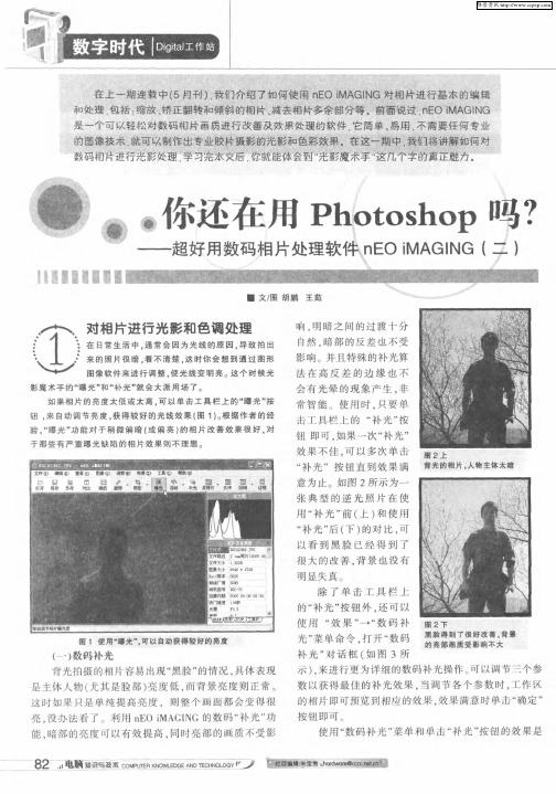
●数码减光利用数码补光功能,暗部的亮度可以有效提高,同时,亮部的画质不受影响,明暗之间的过渡十分自然,暗部的反差也不受影响。
对于追补效果欠佳的照片,可以调节“强力追补”参数增强补光效果。
●高ISO去噪这个高ISO去噪的功能,可以在不影响画面细节的情况下,去除红绿噪点。
同时画面仍保持有高ISO的颗粒感,效果类似高ISO胶片,使DC的高ISO设置真正可用。
●晚霞渲染这个功能不仅局限于天空,也可以运用在人像、风景等情况。
使用以后,亮度呈现暖红色调,暗部则显蓝紫色,画面的色调对比很鲜明,色彩十分艳丽。
暗部细节亦保留得很丰富。
启动该软件后,在【光影魔术手】窗口打开“2.jpg”图片。
该软件的整个界面中,包含有菜单栏、工具栏、功能窗格、和预览窗格,如图5-22所示。
图5-22 【光影魔术手】窗口1.人物美化使用人物美容处理相片可以自动识别人像的皮肤,把粗糙的毛孔磨平,令肤质更细腻白晰,同时可以选择加入柔光的效果,产生朦胧美。
还可以为图像添加撕边效果。
其具体的操作步骤如下:(1)在光影魔术手软件中,单击工具栏中【打开】按钮,在弹出的对话框中,打开“20.jpg ”图片,如图5-23所示。
图5-23 打开图片(2)单击工具栏中【美容】按钮,在弹出的【人物美容】对话框中设置磨皮力度、美白和范围参数,如图5-24所示。

Imaging Mac computer driveswith theForensic Falcon®-NEOTable of Contents1.0 Introduction (2)1.1 Macs with the Apple T2 Security Chip (2)1.1.1 Using the Mac’s Disk Utility (2)1.1.2 Use Targeted/Logical Imaging (File to File) (5)1.2 Apple File System (APFS) (5)1.3 Fusion Drives (6)2.0 USB-C / Thunderbolt 3 (6)2.1 Only one USB-C / Thunderbolt 3 Port (6)2.2 Only Two USB-C / Thunderbolt 3 Ports (7)2.2.1 Target Disk Mode (7)2.2.2 USB Boot Client (7)2.3 More than two USB-C / Thunderbolt 3 Ports (8)2.3.1 Target Disk Mode (8)2.3.2 USB Boot Client (8)2.3.2.1 A USB-C Hub (8)2.3.2.2 Two USB-C Adapters (9)3.0 USB 2.0 / USB 3.0 (9)3.1 Only One USB 2.0 / USB 3.0 Port (9)3.2 Two or More USB 2.0 / USB 3.0 Ports (10)4.0 A Removable Drive (10)5.0 Thunderbolt / Thunderbolt 2 (10)6.0 FireWire (10)7.0 Built-in Ethernet Port (11)Technical Support Information (11)APPNOTE-Imaging_Macs–Falcon-NEO-v1.5 Page 1 of 11 October 20191.0 IntroductionThis document provides guidance on the different ways to access a Mac computer’s internal drive to be used as a Source drive on the Falcon-NEO. This document applies to the Mac line of computers. Different Macs have different available ports. Depending on the ports available on the Mac, there may be more than one way to image a Mac drive. This document outlines the different ports available on Macs and the different ways (if possible) to image the drive depending on the available ports.There are different ways a Mac can be imaged with the Falcon-NEO depending on the Mac computer. Most Macs have one or more of the following:•USB-C / Thunderbolt 3•USB 2.0 / USB 3.0• A removable drive (HDD or SSD)•Thunderbolt / Thunderbolt 2•FireWire•Built-in EthernetDepending on the Mac model, there may be multiple ways of imaging the drive.Logicube does not sell any of the adapters or hubs mentioned in thisdocument. However, most third-party adapters or hubs should work.Fo r the optimal speeds, anytime “Ethernet” is mentioned, it isrecommended to use Gigabit Ethernet for optimal speeds.1.1 Macs with the Apple T2 Security ChipMac computers with the Apple T2 Security Chip have added layers of security that may limit certain ways the drive can be imaged. At this time, there are two ways to image a Maccomputer with the Apple T2 Security Chip:1.1.1 Using the Mac’s Disk Utility1.Connect a formatted external drive to the Mac. The external drive needs tobe formatted using a file system compatible with the Mac OS (e.g., APFS,HFS+, exFAT, etc.).2.Boot the Mac in Recovery Mode by turning on the Mac and immediatelypress and hold Command (⌘)-R on the keyboard. Continue holding until yousee the Apple logo or a spinning globe.APPNOTE-Imaging_Macs–Falcon-NEO-v1.5 Page 2 of 11 October 2019If a login window or the desktop appears,the keyboard combination was not pressedearly enough. Restart the Mac and try again.3.The Mac OS Utilities screen will appear.4.Choose Disk Utility. The Disk Utility app will open.5.In the Disk Utility app, choose File, then New Image, then Image from Folder.6.Select the local Mac drive in the Locations section of the Disk Utility, thenclick Choose.APPNOTE-Imaging_Macs–Falcon-NEO-v1.5 Page 3 of 11 October 20197. A new window will appear. In this new Window:a.In the Save As field, type the name of the image file to create andsave the image to.b.In the Where field, select the connected external drive.c.In the Image Format field, select read-only.d.Click Save. Disk Utility should start creating the folder disk image.8.When the image finishes, click Done. The image file should be in DMG formatand can be opened with any forensic workstation or software that can readDMG files.APPNOTE-Imaging_Macs–Falcon-NEO-v1.5 Page 4 of 11 October 2019APPNOTE-Imaging_Macs –Falcon-NEO-v1.5 Page 5 of 11 October 2019If the external drive was formatted with the HFS+ orAPFS, the workstation and software must also supportthese file systems in order for the drive to be recognized.1.1.2 Use Targeted/Logical Imaging (File to File)The following are required for this method:•Access to the Mac’s Operating System through a user account with Administrative rights. •The Mac and Falcon-NEO connected to the same network (or directly to each other with an Ethernet cable). •Folders/directories on the Mac will need to be shared so the Falcon-NEO can access them. •The shared folder(s) will need to be setup in the Manage Repositories screen on the Falcon-NEO. • File to File imaging mode must be used. See Chapter 4 – Imaging, in theFalcon-NEO user’s manual.1.2 Apple File System (APFS)Mac computers with the Apple File System (APFS) can be imaged using any of the supported methods mentioned in this AppNote. However, Windows does not natively support APFS. Please check with your software analysis company to see if your analysis software supports APFS.Drive contents with the APFS can be viewed using the Falcon-NEO’s File Browser feature with the latest Falcon-NEO software.1.3 Fusion DrivesThe type of drive used by the Mac is not dependent on any of the methods in this document.One exception is the Fusion drive. A fusion drive is a hybrid drive that combines a Hard Disk Drive (HDD) with a Solid State Drive (SSD) that is typically seen as a single drive on a Mac.Fusion drives can be imaged one of two ways:•Using the USB Boot Client, or•Using Target Disk ModeRefer to the the section that corresponds to the type of Mac being used for details on how to use the USB Boot Client or Target Disk Mode.When using the USB Boot Client, the Fusion drive will appear as two separate drives (theHDD and the SSD are shown as two separate drives). Fusion drives can still be imaged using the USB Boot Client but cannot be restored (using the Image to Drive method).When using Target Disk Mode with Fusion drives, the Fusion drive will be seen as a singledrive.2.0 USB-C / Thunderbolt 3For Macs that have one or more USB-C / Thunderbolt 3 ports, there are a few possible solutions that vary depending on how many USB-C / Thunderbolt 3 ports are available.2.1 Only one USB-C / Thunderbolt 3 PortMacs that have the USB-C / Thunderbolt 3 port typically require this port for charging. ForMacs that have only one USB-C / Thunderbolt 3 port, the only recommended method is byusing the following:•USB Boot Client – Please see the following document for full details on the USB Boot Client: /manuals/USB_Boot_Client.pdf.• A USB-C hub –The hub must have the following:•Power Delivery – So that the Mac can be plugged in to a power source.•At least one USB-A 2.0 or 3.0 port – Also for use with the USB Boot Client.•OPTIONAL: An Ethernet Port – For use with the USB Boot Client.If the hub does not have anEthernet port, a USB-A toEthernet adapter is required.APPNOTE-Imaging_Macs–Falcon-NEO-v1.5 Page 6 of 11 October 2019Target Disk Mode is not recommended if thereis only one USB-C / Thunderbolt 3 port becausethe same port is required for charging the Mac.2.2 Only Two USB-C / Thunderbolt 3 PortsSince Macs typically require one of the USB-C ports for charging, if the Mac has two USB-C / Thunderbolt 3 ports, there are two possible methods:2.2.1 Target Disk ModeTarget Disk Mode can be used along with a USB 3.0 male type A to USB 3.1 male type Ccable. Connect the cable to one of the available USB-C ports on the Mac. Connect theother end of the cable to the Falcon-NEO’s USB Source port. Boot the Mac usingTarget Disk Mode (TDM) and the drive should appear as a Source on the Falcon-NEO.Logicube has qualified a USB 3.0 male type A to USB 3.1male type C cable that is included with each Falcon-NEO.For support on how to boot into Target Disk Mode, or tofind out if the specific Mac supports Target Disk Mode withUSB-C / Thunderbolt 3 ports, please contact Apple Support.2.2.2 USB Boot ClientSince there are two available USB-C / Thunderbolt 3 ports, the USB Boot Client canbe used along with a USB-C hub. Since there is a second USB-C / Thunderbolt 3 port,the hub required does not need to have power delivery. Please see the followingdocument for full details on the USB Boot Client:/manuals/USB_Boot_Client.pdf. The USB Boot Client isrequired along with the following:• A USB-C hub with the following:•OPTIONAL: An Ethernet Port – For use with the USB Boot Client.If the hub does not have anEthernet port, a USB-A toEthernet adapter is required.APPNOTE-Imaging_Macs–Falcon-NEO-v1.5 Page 7 of 11 October 2019•At least one USB-A 2.0 or 3.0 port – Also for use with the USB BootClient. At least two ports are required if a USB-A to Ethernet adapteris used.•OPTIONAL: Power Delivery – So that the Mac can be plugged in to apower source. This is not required since there is a second portavailable for power.2.3 More than two USB-C / Thunderbolt 3 PortsFor Macs that have more than two USB-C / Thunderbolt 3 ports, there are several differentmethods:2.3.1 Target Disk ModeTarget Disk Mode can be used along with a USB 3.0 male type A to USB 3.1 male type Ccable. Connect the cable to one of the available USB-C ports on the Mac. Connect theother end of the cable to the Falcon-NEO’s USB Source port. Boot the Mac usingTarget Disk Mode (TDM) and the drive should appear as a Source on the Falcon-NEO.Logicube has qualified a USB 3.0 male type A to USB 3.1male type C cable and is included with each Falcon-NEO.For support on how to boot into Target Disk Mode, or tofind out if the specific Mac supports Target Disk Mode withUSB-C / Thunderbolt 3 ports, please contact Apple Support.2.3.2 USB Boot ClientSince there are more available ports, there are different combinations of items thatmay work with Macs that have more than two USB-C / Thunderbolt 3 ports whenusing the USB Boot Client.Please see the following document for full details on the USB Boot Client:/manuals/USB_Boot_Client.pdf. The USB Boot Client isrequired along with one of the following:2.3.2.1 A USB-C HubA USB-C hub with the following:•OPTIONAL: An Ethernet Port – For use with the USB Boot Client.APPNOTE-Imaging_Macs–Falcon-NEO-v1.5 Page 8 of 11 October 2019If the hub does not have an Ethernet port, one ofthe following is required:- A USB-A to Ethernet adapter, or- A USB-C to Ethernet adapter (to connect directlyto an on-board USB-C / Thunderbolt 3 port.•At least one USB-A 2.0 or 3.0 port – Also for use with the USB BootClient. At least two ports are required if a USB-A to Ethernet adapteris used.•OPTIONAL: Power Delivery – So that the Mac can be plugged in to apower source. This is not required since there are more than 2 portsavailable for power.2.3.2.2 Two USB-C AdaptersRather than using a USB-C hub, two separate adapters can be used:• A USB-C to Ethernet adapter, and• A USB-C (male) to USB-A (female) adapter (for use with the USB BootClient).3.0 USB 2.0 / USB 3.0For Macs that have at least one USB 2.0 (Type A) or USB 3.0 (Type A) port, the USB Boot Client can be used. Target Disk Mode is not supported with USB 2.0 or USB 3.0 ports. Please see the following document for full details on the USB Boot Client:/manuals/USB_Boot_Client.pdf.3.1 Only One USB 2.0 / USB 3.0 PortIf the Mac has only one USB 2.0 or 3.0 port, the The USB Boot Client is required along withone of the following:A USB hub with the following:•OPTIONAL: An Ethernet Port – For use with the USB Boot Client.If the hub does not have anEthernet port, a USB-A toEthernet adapter is required.•At least two or more USB 2.0 or 3.0 ports.APPNOTE-Imaging_Macs–Falcon-NEO-v1.5 Page 9 of 11 October 20193.2 Two or More USB 2.0 / USB 3.0 PortsIf the Mac has two or more USB 2.0 or 3.0 ports, the USB Boot Client is required along withthe a USB-A to Ethernet adapter.4.0 A Removable DriveSome Macs have drives that can be removed. These drives can be Hard Disk Drives or Solid State Drives and the drive’s connector can vary. Some may have standard SATA connectors while others have proprietary connectors.The Falcon-NEO supports drives with standard SATA connectors using the SAS/SATA cables that are included with the Falcon-NEO.Some drives that do not have the standard SATA connector, may still work with the Falcon-NEO, but may require additional third-party adapters, while other drives that do not have the standard SATA connector may not work.Contact Logicube Technical support (********************) to see if a third party adapter might work. When contacting Tech Support, please include the following information:• A clear picture of the entire drive (front and back) which should include the connector pins.•The Mac Model Identifier. For example, as a reference, please see the following pages: ▪MacBook (https:///en-us/HT201608)▪MacBook Pro (https:///en-us/HT201300)▪MacBook Air (https:///en-us/HT201862)5.0 Thunderbolt / Thunderbolt 2For Macs that have the older Thunderbolt or Thunderbolt 2 ports, Target Disk Mode is not possible. Macs that have the older Thunderbolt or Thunderbolt 2 ports typically have other ports that can be used to image the drive (e.g. USB Type A port). Please see the other sections in this document for other ports that may apply to the specific Mac being used.6.0 FireWireFor Macs that have a FireWire port, Target Disk Mode is not possible. Macs that have a FireWire port typically have other ports that can be used to image the drive (e.g. USB Type A port). Please see the other sections in this document for other ports that may apply to the specific Mac being used. APPNOTE-Imaging_Macs–Falcon-NEO-v1.5 Page 10 of 11 October 2019Application NoteAPPNOTE-Imaging_Macs –Falcon-NEO-v1.5 Page 11 of 11 October 2019 Logicube, Inc. • 19755 Nordhoff Pl.,Chatsworth, CA 91311 USA• tel:+1-818-700-8488• fax:+1-818-435-0088 7.0 Built-in Ethernet Port For Macs that have a built in Ethernet port, the USB Boot Client can be used as long as the Mac also has an available USB 2.0 or USB 3.0 port. Please see the following document for full details on the USB Boot Client: /manuals/USB_Boot_Client.pdf .Technical Support Information_________________________Apple, Mac, and FireWire are trademarks of Apple Inc., registered in the U.S. and other countries.Thunderbolt, Thunderbolt 2, and Thunderbolt 3 are trademarks of Intel Corporation or its subsidiaries in the U.S. and/or other countries.。
教你怎么看镜头 MTF 曲线此刻各镜头厂家,各个测试机构所用的 MTF 曲线表现形式都不同样,在下说一下上边这些 MTF 曲线图的简单见解。
MTF 的意义,测试原理就掠过不提了,说来实在话长,并且研究这些理论知识对实质拍照没什么用,我们直接切入正题。
第一是坐标轴,垂直坐标轴的值从 0 到 1,任何状况下数值都是越高越好,假如这世上有一支完满的镜头,它的MTF 全部线条应当是重合的,达到垂直坐标轴极点1,可是没有这样的镜头。
水平坐标轴表示画面地点与中央的距离,对胶片机来说代表着底片,对数码机来说代表着 CCD/CMOS感觉器, 135 相机的对角线长约43."3mm ,所以水平坐标轴的值是从0 到21."7mm 左右,假如是胶片机或许数码全幅机型,从水平坐标轴0 到最右端,就分别代表着画面从中央向来到边沿的质量,但假如是非全幅机型,没有那么大的幅面,就要除以相应的系数,比方 APS-C机型,就要除以1."6 ,结果是13."5mm ,所以假如你用的是APS-C机型,只看到13."5mm 左右就能够了,后边的已经没意义了。
明显,全部镜头都是中央表现最好,越往外头越差(这是空话)。
接下来是线条的意义,图中有黑色线条和蓝色线条,黑色线条表示该镜头光圈全开时的状况,蓝色线条表示该镜头光圈缩短到8 时的状况,一般状况下,缩短光圈后,各镜头的表现都会更好,所以蓝色线条基本都比黑色线条高(这也是空话)。
每种颜色的线条有粗线和细线两种,粗线代表 10 线对 /mm ,细线代表 30 线对 /mm ,1 线对 /mm 表示测试项目为 1mm 内有 1 对黑白相间的线条, 10 线对/mm 代表有 10 对黑白相间的线条,这样类推。
1 线对 /mm 意味着被拍摄的物体是最简单的,反差最大的,最简单被拍摄的,任何镜头都能很简单的表现出这样的画面,线对照越高,就表示每 1mm 内有更多对黑白相间的线条,代表着被摄物体愈来愈复杂,反差愈来愈低,愈来愈难拍摄,所以任何镜头的表现都会随之降落,粗线的地点自然也会比细线高。
NeuraLog数字化软件使⽤说明汇总NeuraLog测井曲线数字化软件NeuraLog测井曲线数字化软件的启动与⼯作界⾯菜单、按钮介绍⼀、NeuraLog软件的启动:在指定⽬录下敲NeuraLog命令启动NeuraLog软件启动主界⾯ ,即以下活动菜单⽤⿏标选择logtutor,User输⼊任意名称,点击OK按钮即可启动NeuraLog⼯作界⾯。
⼆、NeuraLog软件⼯作界⾯主要按钮简介:⽤于定义四点坐标(纵坐标:曲线顶底深度、横坐标;曲线幅度范围)。
⽤于修改曲线坐标值与修正坐标线符合底图。
⽤于曲线深度精确化(选好适当深度间距后,按中键⾃动设置)。
⽤于曲线幅度精确化(选好适当幅度间距后,按中间⾃动设置)。
附属按钮)。
⽤于曲线⾃动追踪及错误修改(左键选择追踪范围)。
⽤于曲线错误修改。
⽤于曲线整体或部分平移(主要⽤于⾃然电位曲线中间的平移归位)。
⽤于擦除曲线错误部分以便与⼿动或⾃动修改。
⽤于剪除部分曲线或曲线错误部分以便修改。
⽤于选择缩放图形⽐例(也可以是任意⽐例)。
X36/m95-31 :⼯区名/井名,Depth axis :曲线深度坐标,Da1 :深度坐标1,Hide grid :隐藏⽹格(起精确化作⽤的⽹格),Remove :移去、删除(⽤于删除Da1),Top::最⼩值(顶深),Bottom::最⼤值(底深),Units :单位,Feet :英尺,Meters :⽶、公尺,Scale axis :曲线幅度坐标,Da1 Sa1 : 深度坐标1中的第⼀根曲线的第1幅度值,Linear :线性的(是选项菜单,展开还包括Logarithmic:对数的、hybrid:混合的、multi-linear:多线的),backup :⽐例选择(如图所⽰:2x、5x等)Remove :删除Da1 Sa1,Lift :左(横坐标坐标值),Right :右(横坐标坐标值),Units :单位(选则曲线幅度单位,包括GAPI、US/F等),Add new :新增(添加曲线主要包括:微梯度/ML1、微电位/ML2、电阻率/Rt0.45、Rt0.4、Rt4.0 、感应/COND、⾃然电位/SP 、⾃然伽玛/GR 、声波/AC、井径/CALI、⼋侧向/LL8、深感应/ILD、中感应/ILM、深侧向LLD、浅侧向LLS。
对焦曲线inf-概述说明以及解释1.引言1.1 概述焦曲线(inf)是一个在摄影和光学领域中常见的概念,它用来描述在不同的焦距下物体清晰呈像的曲线。
随着焦距的变化,镜头对焦的位置也会发生变化,从而使得物体的清晰呈像位置不断改变。
而焦曲线可以帮助我们更好地了解焦距和对焦位置之间的关系,有助于摄影师和光学工程师进行更准确的对焦调节。
在摄影领域,焦曲线的概念对于拍摄清晰、锐利的照片至关重要。
通过了解焦曲线,摄影师能够理解在不同的焦距下,哪些物体会呈现清晰的呈像效果,从而更好地控制景深和焦距,以达到拍摄意图。
同时,对于摄影师而言,了解焦曲线还可以帮助提高对焦速度和准确性,从而捕捉到更精彩的瞬间。
在光学工程领域,焦曲线则被广泛应用于镜头设计和光学系统的优化。
通过研究焦曲线,光学工程师能够更好地了解不同镜头的对焦性能,从而设计出更高质量的镜头系统。
焦曲线也可以帮助优化光学系统的焦深和对焦范围,以满足不同应用领域的需求。
综上所述,焦曲线是摄影和光学领域中的重要概念,对于理解焦距和对焦位置之间的关系以及优化对焦效果具有重要意义。
在本文中,我们将深入探讨焦曲线的定义和原理,以及它在不同领域的应用。
通过研究焦曲线,我们可以更好地理解摄影和光学技术,并为未来的发展提供一定的指导。
1.2文章结构2. 正文2.1 焦曲线的定义和原理在本节中,我们将探讨焦曲线的定义和原理。
焦曲线,即几何光学中的一个概念,指的是透镜或反射镜等光学系统的弯曲曲线。
焦曲线是由光线通过非球面或非旋转对称的反射或折射介质而形成的。
焦曲线的产生是由于不同位置的光线经过光学系统后汇聚或发散的现象。
在焦曲线的原理方面,我们需要了解光线的传播和折射规律。
光线会在不同介质的界面上发生折射和反射。
当光线从一种介质进入到另一种介质时,会发生折射现象,而光线在同种介质中传播时则会沿直线传播。
光线在光学系统中的传播路径遵循折射定律和反射定律,这些定律描述了光线传播中的角度关系。
目录1、文章标记Tag:纸质质感砖块质感 (2)2、文章标记Tag:光影魔术手彩色浮雕效果 (3)3、文章标记Tag:如何更换光影看看背景音乐 (4)4、文章标记Tag:光影魔术手魔术棒功能的开启 (5)5、文章标记Tag:反转片效果处理介绍 (6)6、文章标记Tag:一步处理胶片效果 (8)7、文章标记Tag:负片效果处理介绍 (9)8、补光处理介绍及分解 (10)9、影楼风格冷绿色调处理分解 (12)10、影楼风格冷蓝色调处理分解 (14)11、文章标记Tag:红眼人像处理 (16)12、光影魔术手基础帮助教程 (16)13、光影魔术手界面及设置 (17)14、LOMO效果及制作 (20)15、矫正比例失真图像 (28)16、用光影魔术手压缩图片教程 (29)17、黑白效果介绍 (30)1、文章标记Tag:纸质质感砖块质感如果照相纸采用带纹理的纸张,就会使照片显示某种质感,带来视觉上的更舒适,柔和。
这确实是一种古老而有效的做法。
《光影魔术手》在新的版本中,提供了“纹理化”的处理功能,放在[效果]/[风格化]中。
点击[效果]菜单,在[风格化]一行中选择[纹理化],就会出现纹理化处理的对话框,调整的方法简单,参数和效果非常直观。
对话框中提供3项参数:纹理类型:有纸质、画布、砖墙。
用户可以根据喜好和照片气氛要求进行选择。
纹理缩放:从10%到150%任意改变纹理的密度。
纹理亮度:决定纹理的颜色深度,向左面数字越小纹理就越淡。
左下角的小放大镜图标是缺省参数的预览,随着调整其实际效果会同时在画面是体现出来,所见即所得。
纹理化的效果图2、文章标记Tag:光影魔术手彩色浮雕效果光影魔术手彩色浮雕其实有点等同于立体的锐化,直到物体浮凸出来立体分明,形成浮雕版画的样子。
关于彩色浮雕的效果又是如何呢?首先请参考下图找到光影魔术手彩色浮雕的按钮位置。
点击[效果]/[风格化]/[浮雕画],对话框中只有一项参数“数量”,此参数决定了浮起的程度。
曲线的功能是十分强大的。
与色阶、色调平衡等功能相比,曲线在区域分段调整上的功能更为强大。
例如,在色阶中调整中间的滑块,相当于在曲线中加入一个控制点;而曲线可以加入无数的控制点,并且,即使是一个控制点,其强度也可以控制。
这些,是色阶和色调平衡无法提供的。
我认为,对于数码相片色调方面的控制,曲线较其它功能更为直观、易懂、易掌握,功能强大,效果好。
认真理解曲线的含义和作用,你一定会爱上使用曲线的。
让我们认识一下曲线吧。
在此,我会尽量用简单直白的说法表达我的理解。
为使初学者得到最浅白的信息,表达方式上将尽量主观感性,可能会不尽准确,请勿引用作为理论依据。
希望一个初学者看完这篇文章以后,就可以上手有意识地利用曲线调整数码照片。
打开曲线对话框,我们可以看到三类虚线:横线、竖线、斜线。
横线不管了!
斜线,就是我们需要控制的曲线。
等一下详细讨论。
竖线,是参考作用的。
看下面这个示意
竖线把画面分成一块块的区,左面的区(蓝色方框中的),表示:落在这个区中的线,控制的是画面中比较暗的部分,越暗,越靠左面。
右面的区(红色方框中的),表示:落在这个区中的线,控制的是画面中比较亮的部分,越亮,越靠右面。
看到下面有一个从左到右由黑变白的图吧,这个图就是让你用来做参照的。
你要对黑暗的部分调整,就改变左边的曲线;反之,
你要对明亮的部分调整,就改变右边的曲线。
接下来,换一个角度看。
看下图。
图中,我用红色和蓝色画出两个斜三角的区。
如果你把曲线拖到红色的区域中,那么照片就会比原来更亮。
如果你把曲线拖到蓝色的区域中,那么照片就会比原来更暗。
如果曲线一部分在红色的区域中,另一部分在蓝色区域中,那么照片就会一
部分更亮,更一部分更暗。
是不是有点糊涂了?看个两曲线的实例理解一下吧。
下面这个曲线,左边的曲线向下拉,右边的曲线向上拉。
就是说,原来照片中比较暗的部分,曲线向下拉了以后,就变得比原来更暗了。
而原来照片中比较亮的部分,曲线向上拉了以后,就变得比原来更亮了。
(这根曲线的作用,实际上就是增强了照片的对比度。
)
再看一根反过来的曲线。
下面这个曲线,左边的曲线向上拉,右边的曲线向下拉。
就是说,原来照片中比较暗的部分,曲线向上拉了以后,就变得比原来变亮了。
而原来照片中比较亮的部分,曲线向下拉了以后,就变得比原来更暗了。
(这根曲线的作用,实际上就是减弱了照片
的对比度。
)
以上介绍的两种情况,是在曲线上加了两个控制点,用来分开控制照片中明暗两部分。
你也可以加入更多的控制点,把明暗区域划分得更细。
由于控制点之间是通过曲线连接的,这就意味着,不同明暗区域经过调整以后,过渡会比较平滑,不会出现色块、色斑的情况。
最后还要说明最重要的一点:调整数码照片,一定要分不同的通道对曲线进行不一样的调整。
不同的通道控制的是不同的颜色,同时对它们进行独立地调整,会令照片的颜色发生奇妙的变化。
不同通道对色彩的控制是一种综合作用,相当于调色。
例如,红色通道和蓝色通道同时增加,产生的效果是画面变得更紫了。
而“RGB通道”,则是对所有色彩通道同时进行控制调节,这时色彩就不会发生变化,变化的是画面的明暗。
接下来让我们找一张样片一起练习一下吧!
请看下面这张照片(你可以点击放大它,然后下载到硬盘自己练习)。
这张照片本身的色彩已经很自然很出色了,其实可以不必调整。
但为了练习一下,让我们试试用曲线,调制一些比
较夸张的色彩效果出来。
如果我们需要一种金黄的落日余晖的感觉,那么我们需要对天空的色彩进行重点的调节。
天空在画面中是比较亮的部分,所以,应该主要调节曲线的右侧的区域,而左侧的曲线影响的是暗部,尽量少变化。
为了得到金黄的颜色效果,我们首先打开红色通道,把曲线略微向上提拉;然后再转到绿色通道,同样拉高右部的曲线(注意观察画面的色彩变化哦);由于红色和绿色的亮度增加了,画面中的高光的亮度提高了,这时我们可以适当压低蓝色通道的曲线,令到画
面的亮度均衡,同时也起到一定的色彩调节作用。
三个通道的调整如下:
经过三个色彩通道针对亮部色彩的曲线调整,照片的色调发生了明显的变化:
第二个例子:
刚才的照片,我们换另一种色彩风格。
我们试一下拉高红色和蓝色,拉低绿色。
这时天空的色彩会变成奇异的紫红色,曲线变化的幅度不一样,紫红的程度是不同的。
当然也可以拉高蓝色,同时拉低红色和绿色,只要拉曲线的幅度不一样,就可以拉出不同的色调!例子的
三个通道设置以及效果如下:
关于nEO iMAGING曲线操作的一些解释:
在nEO iMAGING中,曲线控制点的数目是不受限制的,用户可以定制一条有很多控制点的曲线。
当用户在曲线空白的位置点击鼠标,就会为曲线增加一个控制点。
如果点击的位置附近已经有控制点,软件会智能地把附近的控制点移过来。
如果用户想删除控制点,可以按键盘上的DEL按钮。
而用户对调整满意后的曲线,是可以保存为一个曲线方案的。
这样,对相同系列照片,可以使用相同的曲线,以保持色调风格的一致性。