RFC30试剂控制器 操作手册
- 格式:pdf
- 大小:853.52 KB
- 文档页数:21

PG1Operation Guide CT30The CT30 programmable communicating thermostat operates via a high-quality, easy-to-use touch screen. To program or adjust your CT30, simply touch yourfinger firmly to the screen. The screen will automatically light up and you will hear a “beep.” Do not use a sharp or metallic device; it will scratch the screen.ENGLISHStatement of use: 100% Compatible with all popular residential HVAC systems; 24VAC single, two stageconventional heating systems (gas/oil/electric), heat pumps, single stage or with auxilliary heat (electric or fossil), zoned forced air and zoned hot water (2 or 3 wire), millivolt systems (with a 12-24 AC or DC source), one or two stage cooling, andhybrid systems.P status Mode buttonFan buttonnPG2HOME ScreenBefore you operate the CT30 please get familiar with these basic control screens. All the CT30functions are accessed through these screens: HOME, MENU, PROGRAM and MANUAL. The CT30 touch screen technology allows you to select (by touching) an item and change it using the +/- arrows or the time arrows.The HOMEthe unit is operating. Touching the HOME icon on another screenTo set a Mode:The CT30 will step through the you are in.indicatorTemperatureMENU Screen The MENU screen is the gateway to many functions or settings of the CT30. It is displayed when you press the MENU button. [See page 10 for details]Set DaySet TimeUse this to calibrate your LCD display match to another thermometer.o C -o FT ouch for 5 secto lock or unlock.Returnto HOMEscreen.Touch this in OFF mode to�configure the unit to work withyour HVAC system.PG 3PG4PROGRAM Screen The stand alone PROGRAM screen sets the CT30 controlfor your home HVAC system with out a central controller. Press and hold PROG for 10 sec to access it. After that it is displayed when you press the PROG button. [See page 8 for details]T ouch this area to set the day of the week you want to program .Ti Copy[Tlower each Target Temp.[T ouch and hold for fast set.]PG5MANUAL Screen The Manual Screen control screen is where you can maketemporary changes to your CT30’s operation. From the Full HOME screen, touch the main temperature display to use this screen. [See page 13 for details]Return HOMEarrow s emp. T ouch this to invoke a w henTarget TemperatureHEAT PUMP systems.you set until you change it or cancel HOLD.PG6Simple HOME ScreenMake this the default HOME screen for yourCT30 by holding the PROG button for 12 seconds. This Simple HOME screen gives you limited access to the CT30’s on screen display and no programming capability. It makes the CT30 behave like a simple one setting thermostat.The simple screen is useful for people who do not wantsettings.Thermostat Current Room Temperature Target T emp.[T ouch and hold for fast set.]PG7Press MENU to to access the following commands (from HOME screen).Set day of the weekTouch the Day of the week area to cycle through the days of the week to select the current day. Set time of dayTouch the Time of Day arrows to move the time selection forward or backward until it displays the current time. Touch and hold for faster setting.Set o F-o C displayTouch the o F and it will toggle to o C.Set audible chirpTouch the musical note icon to select the chirp or no chirp.Return HOMEby touching the home icon.PG 8 The CT30 comes pre-programmed with an EPA approved program. This program is recommended by the EPA for energy efficiency. We strongly recommend that you Auto-Run this program for one week, and see if it works for you. If it does not fit your needs you can always input a custom program.To run the EPA program, set the mode switch to HEAT or COOL.Press the MENU button and use the arrows by the time display to set the time.Touch the DAY area and advance it to select the present day.TO CHANGE THE PROGRAM:Make sure the CT30 mode is set to either HEAT or COOL, then press the PROGRAM button. Thisputs you at the PROGRAM screen [see page 4]. The programmed start time is displayed in theupper left. The TIME SLOT icon indicates the active TIME SLOT in the default program [MORN, DAY, EVEN, NITE]. The programmed Target Temperature is shown on main display.The HEAT program and the COOL program are separate.PROGRAM cont.Select the day you want to program.The day of the week starts at SU - Sunday and can be advanced to the day you want to program. Touch the day of the week area to cycle through the days of the week to the desired day.Select the time slot (period) you want to program (MORN, DAY, EVEN, NITE).Touch the time slot area to cycle through to the desired period.Select the desired start time of that time slot.Touch the time arrows to select the desired period’s starting time. Hold arrow down for fast time scrolling.Select the desired target temperature for that time slot.Touch the +/- arrows to select the desired period’s temperature.To COPY one day’s programming to the next day, touch COPY DAY once. The information for the current day will be copied to the next day which will appear on the screen. Holding down COPY forover 3 seconds will copy to all 7 days.Touch to return to the Home screen.PG 9PG 100Press MENU to bring up MENU screen.TIME of DAYTouch the left (down) or right (up) arrows next to the time display to set the current time (1 minute per touch). Touch and hold the arrow for fast time set (15 minute jumps).DAY of Week Touch DAY area to select present day.SWING (HVAC cycling rate) This feature allows you to set the desired variance in temperature between the CT30 setting and the room temperature required before the heating or cooling systemwill turn on—from 0.5° to 2.0° F (.25° to 1° C). For example, if SWING is set to 2.0° F and the CT30is set to 70°F Target Temperature, the heat cycle will start when room temperature drops to 68°F. Similarly, the cooling system will start when the room temperature increases to 72°F. The HVAC thenruns and will shut off at the Target Temperature.To set SWING:Touch SWING.Touch the left/right arrows to set the SWING from 0.5° to 2.0°F.The HVAC will run more frequently at .5°F and less at 2°F. Default is 1°F.Touch to return to the MENU screen.Chirp set - Touch this to turn the audible chirp sound on or off.FC Set - Touch this to switch the temperature display scale from o F to o C .FILTER - AIR FILTER ALERT - The CT30 can be programmed to remind you when the HVAC sytem’s air filter needs changing.Touch FILTER. The display will show the usage to date.Touch FILTER for over 3 seconds and the display will change to LIMIT.Touch arrows to set desired usage limit before filter alert comes on home screen.When this limit is reached, FILTER will be on home screen and the CHECK FILTER indicator lights.Limit may be set from 0 to 999 days/99 weeks; default is 90 days/12 weeks. Touch to reset.To reset the usage back to 0, touch usage number; touching it again restores the displayed usage. Touch to return to the MENU screen.LOCK (The CT30 has 2 lock modes)Touch icon for 5 seconds; the unit will go into the PARTIAL lock mode. The user can temporarily override the CT30 target with the +/- buttons only. (1 bar)For FULL lock : Touch the (1 bar) icon again for 5 seconds to go to full lock. No changes can bemade in full lock (2 bars). Once locked, the CT30 will respond just to mode and menu.To UNLOCK , Press MENU.Touch and hold icon for 5 seconds for 2 bars (if not there already).Then touch and hold the icon for another 5 seconds. Each 5 second touch and hold must be separate. Touch to return to the Home screen.PG 11PG 122 CALIBRATE Your thermostat was accurately calibrated at the factory to ±1° F of actual ambient temperature. You do have the option, however, to change the display temperature to match that of a previous thermostat, or to match another thermostat already in your home. The range of change isfrom -6°F to +6°F or -3°C to +3°C.To change your Thermostat Calibration, touch MENU and then touch CALIBRATE.Use the + / - to adjust the displayed temperature up or down, as desired.The DELTA FACTOR that appears on the screen will also automatically increase or decreasefor each 0.5° (F or C) adjustment so you can see your change. The large display will show themodified temerature reading that will be displayed on the HOME screen and used as the new room temperature.Touch to return to the Home screen.DIFF(Used for 2 stage normal or heat pump with auxiliary only, not on screen for single stage)The differential is the number of degrees between the room temperature and the Target Temperatureat which the 2nd stage will be used. Default is 2°F.Touch MENU and then DIFF. Use the arrows to set the DIFF.Recommend 2°F for very cold climates and the 4°F for warm climates.The CT30 has 4 manual override commands. The manual screen is accessed by touching the large current temperature display in the middle of the HOME screen.IMPORTANT: The Mode must be in HEAT or COOL to access the manual screen.TEMPORARY override Touch the + / - arrows to select your desired temporary Target Temperature. Touch HOME to return to operation. The TEMPORARY icon will display indicatingyou have modified the Target Temperature for the current Time Slot only. It goes back to theprogram target at the next period. Also, when in TEMPORARY, if the target is set the same as the programmed target for that period, the word TEMPORARY will go out.HOLD This will hold the target temperature you set indefinitely, until you turn HOLD off. HOLD will allowyou to operate your thermostat as a manual thermostat. It will keep whatever temperature you set untilyou change it or cancel hold. Take care using the HOLD function as the program is now bypassed. To seta hold target temperature, touch HOLD and use the +/- icons to select your hold temperature. The HOLDicon will display on the HOME screen indicating you have changed the Target Temperature. The systemwill HOLD this temperature until you return to the manual screen and de-select HOLD by touching it. Holdis also canceled when you set the mode to OFF.HOLIDAY This is a single program that repeats day after day until you turn it off. It supersedes thePG 13PG 144 weekly program. To use it touch HOLIDAY on the temporary screen. The default holiday program is shown below. To modify this program, touch the PROGRAM button and then touch the DAY area until HOLIDAY appears (after SAT). The default HOLIDAY program is set as 2 time slots; all day (sametarget MORN, DAY and EVEN) and a different target for NITE. [Default program: HEAT 70o F all dayand 62o F at night. COOL 78o F all day and 82o F at night.]EMER (in HEAT PUMP type)If you set your CT30 for HEAT PUMP with auxiliary heat, EMER function is available on the MANUALscre en. If you touch EMER, it displays EMER|ON. Your HEAT PUMP is disabled and auxiliary heatis your sole source of heat. This manual override stays active until you toggle EMER off. Auxiliaryheat is more expensive than the heat pump so use EMER only if the heat pump cannot keep up or is defective.Save Energy ButtonThe “Save Energy” feature on the CT30 provides a simple, easy-to-use way to help you manage your energy use. SAVE ENERGY automatically adjusts your Target Temperature up in COOL or down in HEAT by 4o F. To use Save Energy, press the Save Energy button in the upper left corner of the unit.The screen will now read “Save Energy”. To return to normal operation, press the “Save Energy”button again. This is useful to save energy if you are gone for a short time.MODE ButtonThe mode button sets the CT30 to HEAT COOL or OFF modes. Press it once to step to the next mode. If the CT30 is in OFF and you want to return to the mode you were previously in, touch theOFF indicator on screen.FAN ButtonThe fan control is normally in AUTO mode, meaning that the fan operates automatically with theHVAC system and the thermostat. When the fan button is pressed the fan goes ON; the fan will run continuously in this manual override until switched back to AUTO by pressing the FAN button again. [NOTE: Fan ON function is available in the OFF mode to allow simple ventilating.]Simple ScreenThis display mode limits the amount of information on screen and limits the functions to just the +/- arrows and the MENU button.Hold down the PROGRAM button for 12 seconds to access the limited display screen.Hold down the PROGRAM button for 12 seconds to leave the limited display screen.RESET button The RESET button re-boots the CT30 processor. It does not effect the user programs that have been stored in permanent memory.PG 15PG 166 Compressor Protection The CT30 has a minimum cycle time of 4 minutes to protect your compressor in cool and in heat pump (if you have one). The Home screen will show a small clock andA/C during this time and the compressor will not come on until the 4 minute delay is over.The CT30 has 2 RTM-1 radio ports. These allow your thermostatto communicate with other systems.Using USNAP Radios The USNAP ports allow you to connectyour CT30 to a wireless network. This can give you access to yourhome’s HVAC system even when you are away. It can also giveyou access to web based efficient energy management sites thatcan help you save money and protect the environment.To Insert a USNAP radio module:Power off the CT30. Insert the radio module in either slot on theback of the CT30. Power up CT30.To connect to a network follow the instructions that came with the USNAP module.USNAP port USNAPradio。

DescriptionThe Goldline GL-30 differential temperature controls is designed to provide maximum operating efficiency and flexibility to effectively manage today's innovative solar energy systems. It is a continuation of the advanced electronic technology which produced the popular C-30 and CM-30 controllers - standards of the solar industry since 1975, with hundreds of thousands of units installed worldwide. With an adjustable high limit of 50º-104ºF, the GL-30 is capable of handling most differential temperature control functions for operation of domestic water heating and sophisticated space heating and cooling. The GL-30 is designed to control recirculation, drain-back and closed loop systems.Fast, easy installation -reduces laborDiagnostic LEDs give instant system operation feedbackQuick plug-in system monitoring capability via TD-GLLightning and static elec-tricity protected Proven reliability with outstanding warranty coverageSensors can be located up to 1000 feet away Precision electronic accu-racy within ±1°F Made in the USA!Environment 15° to 130° F 0 to 95% rH Accuracy:+/- 1°FDimensions5.875" x 4.875" x 2.375"Temperature SensorsThermistor 10k @ 25°C/77°F not includedGOLDLINE ® CONTROLS INC42 Ladd Street East Greenwich, RI 02818401 884-6990800 343-0826401 885-1500 faxSp e c i f i c a t i o n sInput p ower120 VAC or 240 VACOutputSPDT powered contacts1HP@115VAC, 2HP@240VAC rating @ 240VAC:20A on NO contacts 10A on NC contacts Differential8/4 to 24/4°F High Limit110° to 230° FGOLDLINE ® CONTROLS INC42 Ladd Street East Greenwich, RI 02818401 884-6990800 343-0826401 885-1500 faxLED IndicatorsThree highly visible LEDs show; 1) power to control, 2) power out from control,3) power out from control due to a recirculation mode to protect the system from freeze damage.GL-30 OutputThe GL-30 output is rated at 20 Amps and is designed to directly operate a pump or fan for heat collection when the controller is sensing an appropriate temperature differentialDifferentialThe GL-30 has an adjustable differential with a range of 8º to 24ºF. Solar systems with long pipe runs normally require a higher turn-on diffeential temperature, and open loop systems with short pipe runs usually require a lower turn-on differenttial temperature for optimum performance. The GL-30offers versatility to tailor controls to numerous specific systems designs.Storage High LimitThe GL-30 allows you to set a high limit storage temperature from 110º to 230ºF.Recirculation Freeze ProtectionRecirculation freeze protection, when enabled, turns the GL-30 output on to circulate warmer storage water through the collectors when near freezing temperatures are reached at the collector sensor.System Test SwitchThe system test switch manually switches the GL-30 to ON, AUTO, or OFF for complete control over the system at all times.Goldline TD-GL Digital MonitorThe GL-30 contains a quick plug-in adaptor for easy connection to aGoldline TD-GL snap-in digital monitor. This combination provides a digital readout of ±1ºF temperature accuracy for maximizing operating efficiency. The TD-GL also has a minimum/maximum memory for temperatures seen at the collector sensor. The TD-GL may be snapped into the cover of the GL-30 series control or mount remotely.The GL-30 may be connected in permanent installations or carried around as a convenient diagnostic tool. By simply plugging into a GL-30 control and reading the collector and storage temperature sensors, the technician can speed service on any job.Goldline SensorsGoldline provides a wide assortment of remote temperature sensors.These 10K ohm thermistor sensors are to be used with all Goldline temperature controls. General use and application specific sensor housings ensure that we have the sensor that will work best for your application.Accessories10 Year Limited WarrantyGoldline Controls Inc. now offers a full 10 year limited warranty on all solar controls and accessories! This warranty will cover repair or replacement of the control at no cost for the first 24 months. For years 3 through 5, the repair/replacement fee will be a maximum of 25% of the current list price, and for years 6 through 10, the repair/replacement free will be a maximum of 50% of the current list price. The best controls now have the best warranty. See the Goldline warranty statement for detail.。

RFC30试剂控制器操作手册戴安中国有限公司技术服务中心2004.2ICS-90/RFC-30使用注意事项1. 开泵后等待压力升至1000psi以上,再打开RFC-30面板的EGC和AES/SRS开关;2. 将高压极限设置为3000psi;3. 仪器运行时,如果出现超压报警,应当迅速关闭AES/SRS和EGC;4. 仪器运行时,如果出现管路泄漏,应当首先关闭AES/SRS和EGC,再停泵;5. 关机时必须首先关闭AES/SRS和EGC,再停泵。
ICS-1000/1500/RFC-30使用注意事项1. 开泵后等待压力升至1000psi以上,再打开RFC-30面板的EGC开关;2. 将高压极限设置为3000psi;3. 仪器运行时,如果出现超压报警,应当迅速关闭EGC;4. 仪器运行时,如果出现管路泄漏,应当首先关闭EGC,再停泵;5. 关机时必须首先关闭和EGC,再停泵。
目录1.仪器介绍﹒﹒﹒﹒﹒﹒﹒﹒﹒﹒﹒﹒ 52.操作﹒﹒﹒﹒﹒﹒﹒﹒﹒﹒﹒﹒ 83.故障指南﹒﹒﹒﹒﹒﹒﹒﹒﹒﹒﹒﹒ 144.安装﹒﹒﹒﹒﹒﹒﹒﹒﹒﹒﹒﹒ 171. 功能介绍RFC30用于控制AES/SRS抑制器和淋洗液发生器(KOH/MSA)。
它既可以由自身的面板控制,也可以由外部仪器采用TTL信号控制。
图1. RFC30控制原理图注意:排气泡时,不要打开抑制器、EGC和CR-TC的控制开关!1.1 前面板①显示屏可以显示抑制器和淋洗液发生器的类型和工作状态,以及错误信息;②RFC ENABLED LED绿色指示灯亮显示RFC准备就绪;③GRADIENT ON LED绿色指示灯亮显示正在进行梯度淋洗;④ DEVICE SELECT(EGC,CR-TC,AES/SRS)绿色指示灯亮显示所选择的设备正在工作;⑤ EDIT▲和▼可以改变显示模式,或者改变参数的大小,按住▲或▼可以连续快速改变;按ENTER键可以确认所编辑的数值或模式;按CANCEL键可以取消所编辑的数值或模式。

杭州美控自动化技术有限公司更多资讯请扫二维码服务电话:400-152-1718杭州美控自动化技术有限公司 U-MIK-PH8.0-M Y CN2第2版pH/ORP控制器使用说明书前言●感谢您购买本公司产品。
●本手册是关于产品的各项功能、接线方法、设置方法、操作方法、故障处理方法等的说明书。
●在操作之前请仔细阅读本手册,正确使用本产品,避免由于错误操作造成不必要的损失。
●在您阅读完后,请妥善保管在便于随时取阅的地方,以便操作时参照。
注意●本手册内容如因功能升级等有修改时,恕不通知。
●本手册内容我们力求正确无误,如果您发现有误,请与我们联系。
●本手册内容严禁转载、复制。
●本产品禁止使用在防爆场合。
版本U-MIK-PH8.0-MYCN2第二版2021年4月安全注意事项为了安全使用本产品,操作时请务必遵守以下描述的安全注意事项。
关于本手册●请将本手册交于操作者阅读。
●在操作之前,请熟读本手册,并对产品有深入了解。
●本手册只对产品的功能进行阐述,本公司不保证该产品将适合于用户的某一特殊用途。
产品保护、安全及改造相关注意事项●为了确保安全使用本产品以及由其控制的系统,操作时请务必遵守本手册中所述说明和注意事项。
如果违反操作规程,则有可能会损坏本产品所提供的保护功能。
对由以上情况产生的质量、性能、功能和安全问题,本公司不承担任何责任。
●为本产品及其控制系统安装防雷装置,或设计安装单独的安全保护电路时,需要借助其他的设备来实现。
●如果需要更换产品的零部件,请使用本公司指定的型号规格。
●本产品不适用于直接关系到人身安全的系统。
如核动力设备、使用放射能的设备、铁路系统、航空机器、船舶设备、航空设备和医疗器械等。
如有应用,用户有责任使用额外的设备或系统确保人身安全。
●请勿改造本产品。
在本手册中使用了以下几种安全标志:危险标志,若不采取适当的预防措施,将导致严重的人身伤害、仪表损坏或重大财产损失等事故。
警示标志,提醒您对产品有关的重要信息特别注意。


离子色谱法测定酱腌菜中的二氧化硫蒋越华;秦玉燕;时鹏涛;李鸿;蓝唯;邓有展;吴凤;陆仲烟;宁蕾【摘要】建立离子色谱法测定酱腌菜中的二氧化硫含量.样品加入盐酸后采用水蒸气蒸馏,以过氧化氢溶液吸收蒸馏释放出的二氧化硫,通过0.45μm滤膜和Ag柱去除杂质,采用AS11-HC阴离子交换色谱柱分离,以KOH淋洗液洗脱,用电导检测器测定.在优化的色谱条件下,硫酸根标准溶液的质量浓度在1.80~18.00 mg/L范围内与色谱峰面积呈良好的线性关系,相关系数为0.9997,硫酸根的检出限为0.006 mg/L.样品的加标回收率为76.9%~92.3%,测定结果的相对标准偏差小于10%(n=6).该方法样品前处理简单,灵敏度高,可用于酱腌菜中二氧化硫的测定.【期刊名称】《化学分析计量》【年(卷),期】2019(028)003【总页数】4页(P9-12)【关键词】酱腌菜;二氧化硫;离子色谱法【作者】蒋越华;秦玉燕;时鹏涛;李鸿;蓝唯;邓有展;吴凤;陆仲烟;宁蕾【作者单位】广西壮族自治区亚热带作物研究所,农业农村部亚热带果品蔬菜质量监督检验测试中心,农业农村部农产品质量安全风险评估实验室,南宁 530001;广西壮族自治区亚热带作物研究所,农业农村部亚热带果品蔬菜质量监督检验测试中心,农业农村部农产品质量安全风险评估实验室,南宁 530001;广西壮族自治区亚热带作物研究所,农业农村部亚热带果品蔬菜质量监督检验测试中心,农业农村部农产品质量安全风险评估实验室,南宁 530001;广西壮族自治区亚热带作物研究所,农业农村部亚热带果品蔬菜质量监督检验测试中心,农业农村部农产品质量安全风险评估实验室,南宁 530001;广西壮族自治区亚热带作物研究所,农业农村部亚热带果品蔬菜质量监督检验测试中心,农业农村部农产品质量安全风险评估实验室,南宁530001;广西壮族自治区亚热带作物研究所,农业农村部亚热带果品蔬菜质量监督检验测试中心,农业农村部农产品质量安全风险评估实验室,南宁 530001;广西壮族自治区亚热带作物研究所,农业农村部亚热带果品蔬菜质量监督检验测试中心,农业农村部农产品质量安全风险评估实验室,南宁 530001;广西壮族自治区亚热带作物研究所,农业农村部亚热带果品蔬菜质量监督检验测试中心,农业农村部农产品质量安全风险评估实验室,南宁 530001;广西壮族自治区亚热带作物研究所,农业农村部亚热带果品蔬菜质量监督检验测试中心,农业农村部农产品质量安全风险评估实验室,南宁 530001【正文语种】中文【中图分类】O657.7酱腌菜是指以新鲜蔬菜为主要原料,经过酱、盐、糖、醋等腌制工序制作而成的各种蔬菜制品的总称[1–2]。
实验室试剂管理系统(单机版)操作手册杨秀君本套软件主要针对实验室试剂信息管理设计开发制作。
软件不仅适用于各实验室试剂管理,同时也适宜作为各部门对进销存数据的管理。
软件当前开通商品入库,商品出库、库存查看及数据统计等功能,支持条码自动扫描功能。
V1.03系统做了全新改版,加入了条码检索、商品分类管理、用户权限设置等多个实用性强的功能,操作界面也做了全新设计,更适应操作习惯。
操作步骤如下:首次运行系统时会自动检测运行环境,并生成数据库框架。
系统新建的用户“管理员”初始密码为:12315,登录成功后,应先进入参数设置,对管理部门的常规项目管理。
系统登录成功后主界面系统参数设置需超级管理员权限才能开启进入,包括商品分类、存放位置、存放条件、商品单位、使用单位及用户管理。
本系统所用简码均取至汉字的拼音缩写字母,方便后期维护用。
系统中每种编码最大长度为20字符,且每组别内的编码必填并不可重复,建议采用年月日加序号格式,如20120131001。
信息添加完成后,编码字段将自动全在先前编码最后一位数字上加一,以防出现重复编码。
用户管理中,可以新增用户,也可删除选定的用户,选中用户复选框,可以更改用户管理权限。
超级管理员可以操作所有已开放的功能,一般管理员除了系统参数设置和库存管理批量操作功能无法使用外,均可使用;一般用户只能出库、入库等常规操作,撤销操作功能也仅限当时才能完成。
系统参数必须设置完全,否则无法进行后期的正常商品管理。
只有完成以下四项参数(系统参数、生产厂家、供货商家和商品信息)设置才能正常入库出库等操作。
窗口化的生产商录入窗口最大化后的生产商录入窗口带有“*”符号的位置为必填内容,带“*”且为红字体的表示必须填写,并且不可重复,编码同样建议采用年月日+序号(如20120131001)格式。
当添加的信息有误时,可以选择删除或是双击右侧对应资料“修正”,供货商信息操作与生产商信息操作同。
商品信息模块应在“系统参数、生产厂家和供货商家”设置完成后使用,操作中需调用前面设置的系列参数。

MX30控制服务器用户手册更新记录目录更新记录 (i)目录................................................................................................................................................................................................................. i i1 简介 (1)2 外观 (2)2.1前面板 (2)2.2后面板 (2)3 应用场景 (6)4 液晶界面 (7)4.1主界面 (7)4.2主菜单 (9)5 初始配屏 (10)5.1液晶快捷配屏 (10)5.1.1设置输入源 (10)5.1.2载入箱体配置文件 (11)5.1.3快捷配屏 (12)5.2 VMP自由配屏 (12)6 显示效果调节 (13)6.1应用预设方案 (13)6.2设置外部输入源参数 (13)6.2.1查看输入源信息 (13)6.2.2设置分辨率和帧频(仅HDMI1、HDMI2、DP) (14)6.2.3调节颜色 (14)6.2.4设置HDR参数(仅HDMI1) (15)6.3设置内置源参数 (16)6.4设置输出参数 (16)6.4.1调节亮度 (16)6.4.2调节Gamma和色温 (17)6.4.3设置低延迟 (18)6.4.4设置输出位深 (18)6.4.5设置同步信号源 (19)6.5设置图层(视频控制器模式支持) (20)7 设备管理 (22)7.1切换工作模式 (22)7.2设置备份设备 (22)7.3进行通讯设置 (22)7.4开启MAPPING (23)7.5控制画面状态 (24)7.6设备自检 (24)7.7查看固件版本 (25)7.8恢复出厂设置 (26)8 系统基本设置 (27)8.1设置语言 (27)8.2设置返回主界面时长 (27)8.3设置温标 (27)8.4查看服务信息 (28)9 产品规格 (29)10 视频源规格 (30)11 网口带载规格 (31)MX30是西安诺瓦星云科技股份有限公司(以下简称“诺瓦星云”)全新控制系统COEX系列下的一款二合一控制服务器,集视频处理和控制功能于一体,具有丰富的视频输入接口(HDMI 2.0、HDMI 1.4、DP 1.1、3G-SDI),10路输出网口和2路10G光纤接口,支持全新的视觉管理平台VMP,为用户提供更好的操控体验。
MATERIAL SAFETY DATA SHEETUnivar Environmental Sciences Emergency Response Telephone Numbers 11305 Four points Drive For Spills Call Chemtrec: 1-(800)-424-9300 Bldg. 1, Suite 210 For Medical Emergencies Call: 1-(866)-674-4334 Austin, Texas 78726 For Other Emergencies Call: 1-(952)-653-3523Product Name: Aqua-Kontrol 30– 30EPA Reg. No: 73748-11INGREDIENTS:(% w/w) Permethrin (CAS Reg. No. 52645-53-1)(3-phenoxyphenyl) methyl (±) cis, trans-3-(2,2-dichloroethenyl) 30.0%-2,2-dimethylcyclopropane carboxylate 1Piperonyl Butoxide (CAS Reg. No. 51-03-6)Equivalent to 80% (butylcarbityl)(6-propylpiperonyl) ether 30.0%And 20% related compoundsInert Ingredients 2 40.0%1 cis/trans ratio: minimum 35% (±) cis and maximum 65% trans2 Petroleum distillate solvent (CAS No. 64741-89-5).Chemical Class: Synthetic Pyrethroid Insecticide and SynergistEPA Signal Word: CautionMATERIAL:OSHA PEL ACGIH TLVActive Ingredients: Permethrin Not established Not establishedPiperonyl Butoxide Not established Not establishedInert Ingredient: Petroleum Distillate 5 mg/m3 (oil mist) 5 mg/m3 (oil mist)EYE: May cause eye irritation, but does not cause irreversible damage to eye tissue.SKIN CONTACT:May cause moderate skin irritation with prolonged or repeated contact. In rare instances, exposure to this product may cause numbing, burning and tingling sensations. These effects are reversible and usually subside within 12 hours.SKIN ABSORPTION: The acute dermal toxicity is considered to be low. The dermal LD50 for rabbits is greater than 2000 mg/kg.INGESTION: The acute oral toxicity is considered to be low. The oral LD50 for rats is greater than 1000 mg/kg. Small amounts that might be swallowed incidental to normal handling operations are not likely to cause injury; however, swallowing larger amounts may cause serious injury, even death. If aspirated (liquid enters the lungs), may cause lung damage or even death due to chemical pneumonia. INHALATION: The acute inhalation toxicity is considered to be low. The inhalation LC50 for rats is greater than 4 mg/l for 4 hours. Symptoms of excessive exposure includes squinting eyes, irregular and rattled breathing, ataxia, headache, dizziness, anesthesia, drowsiness, unconsciousness, and other central nervous system effects.SYSTEMIC (OTHER TARGET ORGAN) EFFECTS: Excessive exposure may produce effects on the nervous system such as sensitivity to touch and sound, tremors, abnormal movement, and clonic convulsions. Long-term studies with permethrin in laboratory animal resulted in increased liver and kidney weights, induction of the liver microsomal drug metabolizing enzyme system, and histopathological changes in the lungs and liver. Long-term studies with piperonyl butoxide indicated increased organ weights in the liver, kidney, and adrenal glands.CANCER INFORMATION: Chronic feeding studies with permethrin in mice and rats indicate limited evidence of oncogenicity in laboratory animals. Based on comprehensive evaluations of all relevant health effects data, it was concluded that the oncogenic potential in humans is extremely weak or nonexistent. A chronic feeding study in mice indicate an increased incidence of benign liver tumors; the significance of these findings is questionable and under review. The doses that produced this oncogenic effect in laboratory animals, greatly exceeds human exposure levels for the recommended use of this product.TERATOLOGY (BIRTH DEFECTS):The active ingredients in this product did not cause birth defects in laboratory animal studies. Exposures having no effect on the mothers had no effect on the fetuses in rabbits and rats. The no-effect levels for permethrin in rabbits and rats were 600 mg/kg and 50 mg/kg, respectively. The no-effect levels for piperonyl butoxide in rabbits and rats were 200 mg/kg and 1000 mg/kg, respectively.REPRODUCTIVE EFFECTS:Permethrin and piperonyl butoxide did not interfere with fertility in animal reproduction studies. The no effect level for permethrin in a two-generation rat reproduction study was 180 mg/kg. The no-effect level for piperonyl butoxide in a two-generation rat reproduction study was 350 mg/kg.MUTAGENICITY (EFFECTS ON GENETIC MATERIAL): Based on a number of in vivo and in vitro studies, it was concluded that the active ingredients in this product are not mutagenic.EYES: Hold eye open and rinse slowly and gently with water for 15 minutes. Remove contact lenses, if present, after the first 5 minutes, then continue rinsing eye. Call a poison control center or doctor for treatment advice.SKIN OR CLOTHING: Take off contaminated clothing. Rinse skin immediately with plenty of water for 15 to 20 minutes. Call a poison control center or doctor for treatment advice.INGESTION: Immediately call a poison control center or doctor. Do not induce vomiting unless told to do so by a poison control center or doctor. Do not give any liquid to the person. Do not give anything by mouth to an unconscious person.INHALATION: Remove person to fresh air. If person is not breathing, call 911 or an ambulance, then give artificial respiration, preferably mouth-to-mouth, if possible. Call a poison control center or doctor for further advice.NOTE TO PHYSICIAN: This product has low oral, dermal, and inhalation toxicity. It is moderately irritating to the skin and is may be irritating to the eyes. Reversible skin sensations (paresthesia) may occur and skin salves have been found useful in reducing discomfort. Contains a petroleum distillate solvent that can produce a severe pneumonitis or fatal pulmonary edema if aspirated during vomiting. Consideration should be given to gastric lavage with an endotracheal tube in place. Treatment is controlled removal of exposure followed by symptomatic and supportive care.For information on this product, contact the National Pesticide Information Center, 1-800-858-7378, Monday – Friday, 7:30 AM – 3:30 PM PST. You may also contact the National Poison Control Center, 1-800-222-1222, day or night, for emergency medical treatment information.CHEMICAL & PHYSICAL PROPERTIES:Color: Clear light amber, Gardner 4Physical State: LiquidOdor: Mild SurfactantDensity: 8.55 lbs/gal (1.025 g/cm3 @ 25° C)Solubility: Dispersible in waterViscosity: 42.4 cps @ 25° CpH: 4.10Stability: StableFIRE AND EXPLOSION HAZARDS:Flash Point: 230º FMethod Used: SetaflashExtinguishing Media: Foam, CO2, or dry chemical is preferred. Soft streamwater fog only if necessaryFire & Explosion Precautions: Foam fire-extinguishing system is preferred becauseuncontrolled water can spread possible contamination.Do not allow fire-fighting water to escape into waterwaysor sewers. Toxic irritating gases can be formed.Fire-Fighting Equipment: Use positive-pressure self-contained breathing apparatusand full protective equipment.REACTIVITY:Stability: (CONDITIONS TO AVOID) Avoid heating above 200º F(93º C). Contains a petroleum distillate solvent which can burn. Incompatibility: (SPECIFIC MATERIALS TO AVOID) Strong Oxidizers. Hazardous Decomposition: Under fire conditions hydrogen chloride, oxides of chlorine, carbondioxide, carbon monoxide, and asphyxiants can be formed. Hazardous Polymerization: Will not occur.IN CASE OF SPILLS OR LEAKS: Wear protective clothing as described in Section VII (Personal Protection and Precautions) of this MSDS. Absorb liquid with material such as clay, sand, sawdust, or dirt. Sweep up and place in a suitable container for disposal and label the contents. Area can be washed down with a suitable solution of bleach or soda ash and an appropriate alcohol (methanol, ethanol, or isopropanol). Follow this by washing with a strong soap and water solution. Absorb any excess liquid as indicated above, and add to the disposal container. Keep product, contaminated materials and wash water out of streams and sewers. Wash exposed body areas thoroughly after handling.DISPOSAL METHOD: Do not contaminate food, feed, or water by storage or cleaning of equipment. Wastes resulting from the use of this product may be disposed of on site, if approved waste handling facilities are available, or at an approved waste handling facility.PHYSICAL ENVIRONMENTAL PROPERTIES: In soil, permethrin is stable over a wide range of pH values. Due to its high affinity for organic matter, (K oc= 86,000), there is little potential for movement in soil or entry into ground water. Permethrin has a Log P OW of 6.1, but a low potential to bioconcentrate (BCF = 500) due to the ease with which it is metabolized. Piperonyl butoxide is reported to have a maximum half-life of 4.3 days in soil and from 0.55 to 1.64 days in aqueous environments. Gravitational settling removes piperonyl butoxide released in the atmosphere as an aerosol. Gaseous piperonyl butoxide degrades in the atmosphere with an estimated half-life of 3.4 hours. It is reported that piperonyl butoxide has a low potential for environmental bioconcentration.ENVIRONMENTAL TOXICOLOGY: Permethrin is highly toxic to fish (LC50= 0.5 µg/L to 315 µg/L) and aquatic invertebrates (LC50 = 0.02 µg/L to 7.6 µg/L). Marine species are often more sensitive than the freshwater species. Bacteria, algae, mollusks, and amphibians are much more tolerant of permethrin than the fish and arthropods. Care should be taken to avoid contamination of the aquatic environment. Permethrin is slightly toxic to birds and oral LD50 values are greater than 3,600 mg/kg. Longer dietary studies showed that concentrations of up to 500 ppm in the diet had no effect on bird reproduction. Piperonyl butoxide is acutely toxic to fish (LC50 = 3.94 mg/L to 6.12 mg/L) and highly toxic to aquatic invertebrates (LC500.23 mg/L to 0.51 mg/L). Care should be taken to avoid contamination of aquatic environments. Piperonyl butoxide has a low to very low toxicity to birds with an acute oral LD50greater than 2,250 mg/kg and longer-term dietary studies at LC50values greater than 5,620 ppm.EXPOSURE GUIDELINE(S):Permethrin None established.Piperonyl Butoxide None establishedPetroleum Distillate 5 mg/m3 (oil mist).VENTILATION: Provide general and/or local exhaust ventilation to control airborne levels below the exposure guideline. Ventilate all transport vehicles prior to unloading.RESPIRATORY PROTECTION:Atmospheric levels should be maintained below the exposure guideline. For most conditions, no respiratory protection should be needed; however, if the exposure guideline is exceeded, use an air-purifying respirator approved for pesticides (U.S. NIOSH/MSHA, EU CEN, or comparable certification organization).EYE/FACE PROTECTION: Use chemical protective goggles or a face shield.SKIN PROTECTION: Wear coveralls or long-sleeved shirt and long pants, chemical protective gloves (nitrile, neoprene, or Viton® brand), head covering and shoes plus socks. For increased exposures, wear a full body cover barrier suit, such as a PVC rain suit. Contaminated leather articles, such as shoes, belts, and watchbands, should be removed and destroyed. Launder all work clothing before reuse. Keep work clothing separated from household laundry.SPECIAL PRECAUTIONS FOR HANDLING AND STORAGE:See product label. Harmful if swallowed, inhaled, or absorbed through the skin. Do not get in eyes, on skin, or on clothing. Wash thoroughly with soap and water after handling and before eating or smoking. Avoid breathing dust vapor, or spray mist. Store in a cool, dry place and away from heat. Keep out of reach of children and animals. Keep away from food, feedstuffs, and water supplies.U.S. SURFACE FREIGHT CLASS: Insecticide, NOI, other than Poison. NMFC Item 102120. MARINE POLLUTANT #1: permethrin (Severe Marine Pollutant).OTHER SHIPPING INFORMATION: This product is not regulated for transport in the USA when shipped via highway or railroad in non-bulk packages. Describe using the “U.S. Surface Freight Class” above, which applies in all cases.* * * * *SPECIAL NOTE: The following applies to water and air shipments, and shipments in bulk packages: PROPER SHIPPING NAME: Environmentally hazardous substance, liquid, n.o.s. (permethrin) HAZARD CLASS OR DIVISION: 9IDENTIFICATION NUMBER: UN 3082PACKING GROUP: IIIOTHER: NAERG Guide 171SARA 313 INFORMATION: This product contains the following substances subject to the reporting requirements of Section 313 of Title III of the Superfund Amendments and Reauthorization Act of 1986 and 40 CFR Part 372:CHEMICAL NAME CAS NUMBER CONCENTRATION Permethrin 52645-53-1 30.0%Piperonyl Butoxide 51-03-5 30.0%SARA HAZARD CATEGORY:This product has been reviewed according to the EPA “Hazard Ca tegories” promulgated under Sections 311 and 312 of the Superfund Amendment and Reauthorization Act of 1986 (SARA Title III) and is considered, under applicable definitions, to meet the following categories:An immediate health hazardA delayed health hazardTOXIC SUBSTANCES CONTROL ACT (TSCA): All ingredients are on the TSCA inventory or are not required to be listed on the TSCA inventory.OSHA HAZARD COMMUNICATION STANDARD:This product is a “Hazardous Chemical” as defined by the OSHA Hazard Communication Standard, 29 CFR 1910.1200.NATIONAL FIRE PROTECTION ASSOCIATION (NFPA) RATINGS:Category RatingHealth 1Flammability 1Reactivity 0COMPREHENSIVE ENVIRONMENTAL RESPONSE COMPENSATION AND LIABILITY ACT (CERCLA, or SUPERFUND): This product contains the following substance(s) listed as "Hazardous Substances" under CERCLA which may require reporting of releases:Category:Chemical Name CAS Number RQ% in ProductPermethrin 52645-53-1 not listed 30.0%Piperonyl Butoxide 51-03-6 not listed 30.0%Petroleum Distillate 64741-89-5 not listed 24.6%Issue Date: January 30, 2014This document is prepared pursuant to the OSHA Hazard Communication Standard (29 CFR 1910.1200). In addition, other substances not “Hazardous” per this OSHA Standard may be listed. Where proprietary ingredient shows, the identity may be made available as provided in this standard.NOTICE: The information herein is presented in good faith and believed to be accurate as of the effective date shown above. However, no warranty, expressed or implied, is given. Regulatory requirements are subject to change and may differ from one location to another; it is the buyer’s responsibility to ensure that its activities comply with federal, state, and local laws and regulations. See MSDS for health and safety information.。
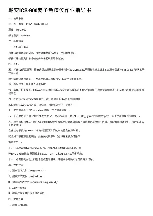
戴安ICS-900离⼦⾊谱仪作业指导书⼀、使⽤条件⽔、电:电源:220V,50Hz 接地线温度:10~30℃相对湿度:25~85%⼆、操作步骤⼀.开机前的准备:打开⾊谱仪器室的空调,打开稳压电源和UPS(不间断电源);根据样品的检测和⾊谱柱的条件来配制所需淋洗液。
四.开机五.打开N2钢瓶总阀,调节钢瓶减压器上的分压表指针为0.2Mpa左右,再调节⾊谱主机上的减压表指针为5 psi左右;确认离⼦⾊谱与计算机数据线连接正常,打开离⼦⾊谱主机和RFC-30溶剂控制器的电源;然后打开计算机进⼊操作系统。
六.选择开始>程序>Chromeleon>Sever Monitor或双击屏幕右下⾓快捷图标,出现对话界⾯后点击Start启动,等Dongle序号出来以后(表⽰Sever Monitor程序运⾏正常)可以点击Close来关闭界⾯,若配置好与Windows系统⼀起启动,则直接进⾏下⼀步操作。
七.双击在桌⾯上的Chromeleon图标(⼯作站主程序)。
⼋.点击根⽬录下⾯的“控制⾯板”⽂件夹,双击右边窗⼝中的“ICS-900_System控制⾯板.pan”(离⼦⾊谱操作控制⾯板)。
九.控制⾯板打开后,选中Connected使软件和离⼦⾊谱连动起来(如果按照正常程序开机,则仪器⾃动连接);打开副泵头上的废液阀,在此状态下保持3-5min,淋洗液瓶⾄泵头间的⽓泡将会在氮⽓压⼒的作⽤下被排放⾄废液瓶;然后关闭废液阀(此步骤主要为排除⽓泡时使⽤)。
⼗.将流速设置1.0 ml/min,开启泵,待压⼒升⾄1000psi以上时,打开RFC-30试剂控制器⾯板上的EGC、CR-TC和AES/SRS,平衡系统。
⼗⼀.点击控制⾯板上的蓝⾊圆点查看基线,等基线稳定后即可分析待测样品。
三.分析样品:1.建⽴程序⽂件(program file);2.建⽴⽅法⽂件(method file);3.建⽴样品表⽂件[sequence(using wizard)];4.启动样品表;5.按系统提⽰进⾏逐个进样分析。
ICS1500/RFC30/AS40型离子色谱仪操作指南1、使用的超纯水为新制,使用之前用抽滤装置先过滤再继续抽真空约5分钟左右。
(最好装差不多满瓶子)2、倒空废液桶中废液,防止其溢出。
3、接好淋洗液瓶管路,暂不拧紧瓶盖,开启氮气瓶总开关,分压表调至0.3Mpa左右,调节淋洗液瓶上的压力表调至5-10psi左右,放气2分钟左右,拧紧盖。
4、打开稳压电源开关,待稳压电源稳定后,再打开ICS1500主机、RFC30发生器(阴离子)的电源开关。
5、启动电脑。
(密码:409)6、启动变色龙软件双击桌面上“Chromeleon”快捷键进入变色龙软件的仪器控制界面,若没有自动弹出控制面板,则点击第二行工具栏中的“默认面板”图标,在右方框中“我的电脑”下选择“Chromeleon服务器”后按“确定”键,即为仪器的控制界面。
7、在左侧方框上边的“联接”前打“√”,使软件与仪器之间建立起联接。
若已经打上“√”,则不需要重新打“√”。
8、拉开ICS-1500主机的前盖,反时针旋松下方右泵头上的启动阀(约拧松2圈左右),用10ml注射器或小烧杯来接废液,再点击软件控制面板左上方“淋洗液阀”模块下的的“打开”键,排除管路中存在的气泡,约排出20ml废液后,再按“关闭”键,然后拿开注射器或小烧杯,最后旋紧右泵头启动阀,注意不要拧得太紧,防止损坏密封圈。
9、反时针旋松左泵头上的废液阀(约拧松2圈左右),点击软件“泵”模块下的“开泵”,并确认泵流速是否为1.0ml/min,排除泵头里残留的气泡。
约1分钟左右,停泵,并旋紧左泵头废液阀。
注意不要拧得太紧,防止损坏密封圈。
10、在控制面板中ICS-1500 泵”模块中按下方的“开泵”。
待压力升至1000psi以上且基本稳定后,在软件中“阴离子淋洗液发生器”下设定开关为“Closed”,使ICS1500与RFC30连接,此时RFC30前面板上的“CR-TC”和“EGC”键,指示灯亮并不闪烁,捕获柱和发生器已开始工作。
30 Lb. Country Smokehouse Assembly and Operating Manual1500 Clinton St. Bldg. 123, Buffalo, NY 14206Tel: (716) 824-5814 • Fax: (716) 824-646530 Lb. Country Smokehouse Operating ManualTable of Contents PageIntroduction 1Smoking Meat 1Important Safeguards 2Operating Instructions 2Troubleshooting 3Cleaning 5Warranty 5Limitation of Liability 5Specifications/Parts List 6Assembly Instructions 7IntroductionCongratulations! You have purchased a smokehouse designed, engineered and constructed by a company with 30 years experience in creating products for making homemade sausage. The materials used will give you years of trouble-free service, provided that you carefully follow the use and maintenance instructions in this manual. Please remember that this smokehouse must always be monitored when in use. Like any piece of cooking equipment, it generates heat that, if not controlled, may lead to fires and possible injuries.Smoking MeatSmoking meat can accomplish two things simultaneously: it can prepare meat for long term storage and impart unique flavor profiles depending on the ingredients and methods used. There are so many different recipes and methods that they cannot be adequately covered in this manual. We recommend that you purchase a complete book on sausage makingto get the most out of this smokehouse. The most thorough text of this subject is Great Sausage Recipes and Meat Curing by Rytek Kutas. This book is available on our website as well as through many bookstores and some local libraries.Important Safeguards1. Read ALL of these instructions thoroughly before using.2. Save these instructions for future reference.3. Never leave your smokehouse unattended.4. Never use your smokehouse indoors.5. Close supervision is necessary when this smokehouse is used near children. NOTE: This machine is not intended for use by children.6. Smokehouses are major appliances and should only be used by a person that isfamiliar with smoking procedures.7. This smokehouse operates at 110 volt, 9 amps and should be serviced only by aqualified electrician. Failure to do so may result in electrical shock, bodily injury orproperty damage.8. As with any electrical appliance, basic safety precautions should always be followed. Your smokehouse is really a cooking utensil and needs your complete attention. It is no different from using an oven, barbecue grill or frying pan at home. We all knowwhat can happen if they are left unattended for any length of time. Follow basic safety precautions and enjoy your smokehouse.9. To protect against electrical shock, do not immerse cord, plugs or heating element in water or other liquid. Avoid using this smokehouse in the rain.10. Unplug this smokehouse when not in use.11. Unplug this smokehouse before cleaning or servicing.12. Do not operate any appliance with a damaged cord or plug, after the appliance malfunctions, or has been damaged in any manner.13. Extreme caution must be used when moving any appliance. Do not move this smoke house while operating.14. If there are any questions about this appliance, contact the manufacturer.Operating InstructionsOur smokehouses are about as simple to operate as your kitchen stove. The proper and efficient operation of this smokehouse rests with you. This appliance is equipped with one control or thermostat and a thermometer located on the upper left hand outside panel. The thermostat control has a range from 50° F to 200° F. The ideal temperature when smoking sausage is 165° F. This can be monitored by checking the thermometer.THE SMOKEHOUSE TEMPERATURE SHOULD NEVER EXCEED 170° F AT ANY TIME WHEN SMOKING MEATS.The 30 Lb. capacity smokehouse is designed to hold 30 lbs. of meat (sausage, bacon, hams, hindquarters). If overloaded, the time from start to finish will greatly increase.ONLY OPERATE THIS APPLIANCE AFTER YOU HAVE READ AND UNDERSTAND THESE INSTRUCTIONS. IF YOU HAVE ANY DOUBTS, CONTACT THE MANUFACTURER.Operating Instructions, cont’d1. Fully open the damper located on the top of the smokehouse by turning the lever on the damper stack. Preheat the smokehouse to 130° F by turning the smokehousecontrol, located below the door, to between Low and Medium. Monitor the insidetemperature on the dial thermometer inserted through the hole in the door. Adjust the temperature by turning the smokehouse control in 1/8 turn increments until the desired temperature is reached.2. While you are waiting for the smokehouse to preheat, dampen the sawdust. Do notsoak it or get it too wet or it will create extra moisture that will condense on the inside of the smokehouse. On the other hand, if it is too dry, it may create an open flamewhich may scorch the meat and/or damage the smokehouse. There are three waysto check if your sawdust has reached the proper dampness: 1. There should be novisible water collecting in the bottom of the sawdust pan, 2. All of the sawdust should now be a darker color, 3. When you pick up a little more than a pinch of sawdust and squeeze it in your fingers, water should not drip out. The amount of sawdust usedgreatly depends upon individual taste. Using one full pan is a good place to start, but you can use more if you desire a stronger taste. Set it aside for Step 4.3. After approximately 15 minutes, place the product you will be smoking in thesmokehouse, close the door and let the product dry for 30-45 minutes at 130° F.4. Open the smokehouse door and carefully place the sawdust pan with sawdust in it.(TIP: Pack the dampened sawdust in the pan and create a hole in the middle ofsawdust. This will help to keep the sawdust smoldering and create a heavy smudge.) Close the door, leave the damper open and turn the smokehouse control to High.5. When you see smoke coming from the smokestack (this could take up to 10 minutes), lower the temperature to 140-145° F and hold at this temperature by turning thesmokehouse control in 1/8 turn increments until the desired temperature is reached. Close the smokestack to 1/4 open (repeat Step 4 if smoke stops).6. Raise the temperature every 1 1/2 hours until the smokehouse temperature reaches 160-165° F. Hold at this temperature until the internal temperature of the product you are smoking reaches 152° F.7. When 152° F is reached, turn off the smokehouse and carefully remove sausage.8. Shower with cold water until the internal temperature reaches 120° F.9. Refrigerate sausage overnight. Product is now ready to eat or freeze.TroubleshootingWhat happens during the smoking process?During the smoking process, smoke emits acids which cling to the meat and to the outside layer of skin. This acid helps preserve the meat by preventing the growth of surface mold and bacteria compounds.How long does it take to smoke a sausage?A 19 mm casing takes approximately 7 hours, a 32-35 mm casing takes approximately 8 hours, a 3 1/2” synthetic casing may take up to 12 hours, and a ham can take a couple of days.Troubleshooting, cont’dHow do I know when the meat is smoked?You can identify that your meat is fully smoked by the distinctive color that develops as a result of the carbon compounds combining with the meat pigments. Also, the cures that are used will give smoked meat a red color.How do I use the sawdust or wood chips?The sawdust or wood chips should be dampened, yet not soaked. Dampened sawdust will burn for a longer period of time and will impart gentle flavors into the meat. To dampen, place sawdust in a bucket or bowl and squirt with a water bottle. You should mix the saw-dust as you add the water to make sure all of the sawdust is moistened.Can I cold smoke with my Sausage Maker smokehouse?It all depends on what you mean by “cold smoke”. Cold smoking refers to a smoking process in which the heat source is in one area while the smoke is forced into another area where the meat product is. In other words, the meat will have a smoked flavor, but willnot be exposed to heat. If you are referring to making sausage and keeping the tempera-ture within the 170 degree area, then yes, this is what our smokehouses are designed for. Smoking sausage is a slow process. The temperature of the smokehouse should be between 165 degrees and 170 degrees. When the temperature rises higher, between 190 degrees and 200 degrees, the fat breaks down, and over 200 degrees you will melt the fat.Can I use liquid smoke and still use my smoker?Yes, you can. Just add liquid smoke to your spices and mix with the meat. Then proceed to use the smokehouse at the low temperatures as instructed.Can I put more sausage in my smokehouse than suggested?No. If overloaded, the time from start to finish will be greatly increased. Also, if the meat is touching there will be discoloration where the smoke was not able to penetrate the meat.Can I do BBQ Ribs in my smokehouse?No. The Sausage Maker Smokers are made for the sole purpose of smoking meat and are meant for temperatures no higher than 190 degrees. If the temperature goes higher the fat melts, which can cause the heating element to burn out or may cause a fire in the smoke-house itself.Why was there liquid on the bottom of my smokehouse after smoking?Your temperature was too high and it melted the fat in the meat.My sausage does not look good, it is shriveled. What do you think was theproblem?There could be several reasons for these results. The temperature may have risen too high and either melted or repositioned the fat. Also, the sausage may not have been showered with cold water immediately after it was finished smoking. Finally, the sausage casings may not have been stuffed to their full capacity.Most of my sausage has a nice mahogany color, but there are areas of whitespots. Why?If the sausage was touching during smoking, the smoke was not able to penetrate that area, leaving a white spot after smoking. There is no problem with your sausage.Cleaning and MaintenanceYour smokehouse has been designed to give you years of trouble-free service, provided that it is properly maintained. After each use, unplug the smokehouse and allow it to cool. Do not try to clean it while it is still hot. Wipe it down with a good cleaner or detergent. If possible, avoid scouring the surface as this will mar the finish and promote sticking in sub-sequent uses. The Sausage Maker, Inc. carries a smokehouse cleaner that does a great job. If you have excessive amounts of dripping or if there is liquid in the bottom of your smokehouse, it should be cleaned up immediately.WarrantyThe Sausage Maker, Inc., through its Distributors, warrants each new product sold by it to the initial user to be free of defects in material and workmanship for a period of one year from the date of sale of the equipment. With respect to the sale of spare parts, such warranty period shall be three (3) months from the date of sale.The Sausage Maker, Inc. will provide a new or repaired part, at its election, in place of any part which is found upon inspection to be defective in material and workmanship during the period described above. Purchaser must present proof of purchase and purchase date at the time of exercising this warranty.This warranty does not apply to failures occuring as a result of abuse, misuse, negligent repairs, corrosion, erosion and normal wear and tear, alterations or modifications made to the product without express written consent of The Sausage Maker, Inc. or failure to follow the recommended operating practices and maintenance procedures as provided in the products operating and maintenance publications.The warranty provided herein does not apply to equipment sold hereunder but manufactured by others as they are warranted by their respective manufacturers directly to the user. This warranty is in lieu of all other warranties (except of title) expressed or implied and there are no warranties of merchantability or of fitness for a particular purpose. Limitation of LiabilityThe remedies of the user set forth under the provisions outlined above are exclusive and the total liability of The Sausage Maker, Inc. or its distributors with respect to this sale of the equipment and service furnished hereunder, in connection with the performance or breach thereof, or from the sale, delivery, installation, repair or technical direction covered by or furnished under this sale, whether based on contract, warranty, negligence, indemnity, strict liability or otherwise shall not exceed the purchase price of the unit of equipment upon which such liability is based.The Sausage Maker, Inc. and its Distributors shall in no event be liable to the user, any successors in interest or any beneficiary or assignee relating to this sale for any conse-quential, incidental, indirect, special or punitive damages arising out of this sale for any breach thereof, or any defects in, or failure of, or malfunction of the equipment underthis sale whether based upon loss of use, lost profits or revenue, interest, lost goodwill, work stoppage, impairment of other goods, loss by reason of shutdown or non-operation, increased expenses of operation, cost of purchase or replacement power claims of user or customers of the user for service interruption whether or not such loss or damage is basedSpecifications/Parts ListSpecifications & Dimensions:• 120 Volt, 1000 Watt Heating Element with Control• Inside Dimensions: 16 1/4” W x 15” D x 31 1/2” H (max.), 14” H (min) • Outside Dimensions: 22 1/2” W x 19 3/4” D x 55 1/4” H• Shipping Weight: 62 Lbs.Equipped With: Part # • Textured Aluminum walls and Stainless Steel bottom inside• 1” Non-sagging insulation• 4 Chrome Plated Shelves 32731 • 3 Hickory Hardwood Dowels 41200 • 7 3/4” Stainless Steel Sawdust Pan 41600 • Baby Dial Thermometer 49400Optional Equipment:• Stainless Steel Shelves 32733 • Smokehouse Cleaner & Degreaser 31450 • Stainless Steel Cleaner & Polish 31542 • USDA Approved Hickory Smoking Sawdust 31450Provided Parts• 4 Legs• Chimney• 2 Screws (on underside of roof)• 12 Screws (attached to smokehouse walls)• Silicone SealantPart 1: Attach Legs1. Lift the roof off of the unit and set the roof aside for Part2. Turn the unit on its back.2. Lay out all four legs as shown in the picture below. The first two legs are for the leftand right, respectively, of the front of the smokehouse and the second two legs are for the left and right, respectively of the back of the smokehouse.1 23. There are 12 screws in the sides of the smokehouse walls. Remove these screws and set them aside.4. Align the legs with the outside corners of the smokehouse walls, lining up the holes in the legs with the new holes in the side of the smokehouse. Screw in the providedscrews to secure the legs to the smokehouse walls.Part 2: Install Chimney1. Turn the roof on its side. Near the hole for the chimney you will see 2 screws. Detach the screws and set them aside.2. Turn the roof upright again. Insert the chimney into the hole in the roof. It will only fit one way, allowing for the tabs to line up with the screw holes on the underside of the roof.3. Turn the roof on its side again. The tabs, which are now on the underside of the roof, should be in line with the screw holes.4. Bend the tabs backwards so that they are flush against the sides of the roof. Screw the chimney into place with the screws that you set aside.5. Seal the edges where the roof and the chimney meet, shown in the image below witha red line, to prevent heat and smoke from escaping during use. The sealant isprovided.6. Once the sealant has dried properly (reference instructions on the bottle of silicone sealant), your smokehouse is ready to use. Set the roof back onto the unit and follow the smokehouse’s operating instructions to start the smoking process.10The Sausage Maker, Inc.1500 Clinton St. Bldg. 123, Buffalo, NY 14206 Tel: (716) 824-5814 • Fax: (716) 824-6465 。
RGC3000色谱软件操作使用简介安装RGC3000- 创建一个要装入该软件的目录,例如C:\RGC 3000- 将Instromet.oem 和Setupprostation.exe 从拷贝到该目录下- 运行文件setupprostation.exe- 按照指示,一定要选择你刚才创建的目录作为软件的安装目录- 如果Windows 跳出一个让你插入原始Windows 光盘的消息,点击取消并继续。
下同。
- 后面的图标将生成在桌面上与EnCal3000连接连接软件的时候,将自己电脑的IP地址设置在与色谱地址在同一个网段,只需要设置IP地址和子网掩码即可,如下:一般子网掩码会自动生成,常用的是255.255.255.0,IP需要跟色谱在同一个网段,如需要连接的色谱IP地址为10.16.1.XX(具体应咨询当时调试的工程师),则将自己电脑的IP 设置为10.16.1.YY。
Note:在开始操作之前,请关掉电脑的防火墙和杀毒软件。
360软件也需要关闭。
Password(密码) demoFile-New在title里面,输入一个你想取的名称比如,叫83373,如下然后单击Configure然后点击Set up ip address,在IP address里面输入跟你电脑取得连接的色谱分析仪的IP地址,子网掩码一般都无需输入,一般采用默认配置,然后点击Ping然后,你可以看到Ping通的状态,如下图Ping成功之后,点击Find EnCal 3000 on the subnet,之后点击“Close”Note:若在点击“Find EnCal 3000 on the subnet”若在空白处不能识别该色谱,则你需要重新重复上述步骤。
然后点击Upload Config然后你会看到在Instrument Serial Number里面会出现与你笔记本相连接的色谱分析仪的序列号。
然后点击OK,这样你就会在主操作界面发现一个色谱的图标,如下:双击色谱的图标,即可进入色谱的控制界面,如下:等十秒钟之后,选择View-Application workspace 然后就可以发现如下色谱主控界面:Note:如果你的色谱正在持续不断的进行分析,那么你需要想将自动分析停止下来。
ICS-1100离子色谱仪参数配置资料来源:南京途威仪器设备有限公司免费热线:4008-585-600ICS-1100离子色谱系统ICS-1100是为等度淋洗而设计的仪器,配合淋洗液自动发生装置(RFC-30)使用也可具有梯度淋洗功能。
选配免化学试剂电解样品前处理装置(RFIC-ESP),利用阀切换和电解水原理,可以用于多种基体样品的不同前处理。
当选配淋洗液在线循环装置(RFIC-ER)时,ICS-1100可以保证连续四周不间断工作且无需更换淋洗液。
主要特点高性能泵高技术的双柱塞高压泵可以提供高精度,低漂移和无脉动的淋洗液。
确保基线的稳定,获得极低的检出限。
全PEEK材料流路设计避免了金属的污染,能够耐高压、耐酸碱、耐反相有机溶剂。
控温电导池体积小、高效控温的电导池提供了高灵敏度和稳定性,并可在任何实验室条件下稳定工作。
带有“自动范围设定”数字控制功能,提供了很宽的动态范围,允许高含量组分和低含量组分在一次进样中同时被检测。
全自动电解抑制器支持全部赛默飞的抑制器技术,自动电解膜抑制技术无需配制酸或碱再生液,提供更低的噪声,更高的灵敏度和更少的日常维护。
不必担心由于柱抑制器容量低需切换再生带来的实验条件不确定问题。
USB连接方式,即插即用即插即用式高速USB数据接口可以快速与任何电脑和其它装置连接,在线识别和自动配置功能为使用者提供方便和简化的系统配置。
电子日志功能,可以对仪器的所有工作状态进行实时监控。
可选配免化学试剂淋洗液在线循环装置当ICS-1100配有免化学试剂淋洗液在线循环装置时,仪器可以稳定地运行28天以上,在这四周时间内使用者不需要更换淋洗液。
自动样品前处理装置(RFIC-ESP)选配免化学试剂电解样品前处理装置(RFIC-ESP),利用阀切换和电解水原理,可以用于多种基体样品的不同前处理,简化实验过程。
可选配淋洗液自动发生装置(RFC-30)配合淋洗液自动发生装置(RFC-30)使用可具有梯度淋洗功能。
Installation and Operation Manual30/40COMBINATION UNITSwith the268/742 Logix Control ValveOctober 2006Table of ContentsPageNo.Topic Description1 Model # and Packaging Packaging InformationComponent PackagingDescriptionPackaging Description MBA Logix Control Valve Valve Description2 Softening System System PositioningCombination Unit Tank Loading Filling with Media3 Logix 268/742 Control Valve Attaching Valve to TankFigure 1 & Figure 24 Service & Drain Piping,General Installation Layout Drain Piping Figure 35 System Schematic Piping Layout6 Electrical Supply Electrical RequirementsBrine Tank / Brine Tubing Brine tank w/shut off7 Logix 268/742 Control ValveElectrical Connection Instructions on Logix 742 Electrical ConnectionFilling Combination Unit withWaterDetails for Filling Tank with Water8 Filling Combination Unit withWater Continued Details for Filling Tank with WaterContinuedLogix 742 Control Valve TimerSettingsSetting the Timer9 Logix 742 Control Valve TimerSettings Continued Setting the Timer Continued10 Logix 742 Control Valve TimerSettings Continued Setting the Timer ContinuedFinal Check Final Installation Check11 Troubleshooting Symptom / Cause / Solution12 Troubleshooting Symptom / Cause / Solution13 Troubleshooting Symptom / Cause / Solution14 ERR Troubleshooting Error Troubleshooting15 268/742 Valve Body Schematic Parts View16 Valve Body Parts List Part Numbers List17 Valve Parts List Part Numbers List18 Warranty WarrantyInstallation and Operating Instructions for268/742 LogixTop Mount Combination UnitModel #:____ FES-30T ____ FES-40T Iron Filter and Softener____ NS-30T ____ NS-40T pH Control and Softener____ TS-30T ____ TS-40T Dechlorination and SoftenerShipping Carton Description / unit:# ofcartonsContents Description1 Mineral tank Distributor pipe installed1 Brine tank 464 shutoff valve assembly. *NOTE:268/742 Logix valved is shipped inbrine tank.1 268/742Logix controlvalve 268/742 timer and backwash flow control and bypass with 1” copper or pvc connectionBirm for FES ½ CF BoxesCalcite for NS ½ CF BoxesNS-Mix for NS ½ CF BoxesCarbon for TS ½ CF BoxesSystem Description:The combination unit has a Logix top mounted automatic control valve with an electronic timer to initiate regeneration. The Logix Valve is constructed of non-corrosive Noryl material and is rated at a maximum working water pressure of 100 psi. It uses a 742 microprocessor based timer to actuate regeneration in the following ways:a. Manual regeneration button to start an emergencyregenerationb. Regeneration day settingCombination Unit Positioning:1. Place combination unit in desired position, far enough from wallsand other obstructions to allow for servicing the unit.2. Place the combination unit within reasonable access to agrounded 115V/60 HZ circuit and a legal drain line connection. Combination Unit Tank Loading:1. Remove yellow caplug from top of tank. DO NOT CUT whiteriser tube. Tube was prefitted at the factory.2. Center the distributor and make sure it is resting on the bottom ofthe tank. The top of the distributor pipe will extend above the topof the tank (this was prefitted at the factory).3. Cover the top opening of the distributor pipe before filling thetank with media.Model Carbon Birm CalicIte NS-Mix TS-30 & 40T 1-cubic footFES-30 & 40T 1-cubic footNS-30 & 40T ½-cubic foot ½-cubicfoot 4. Pour all filter media provided with the unit into the top of the tank.See page one for your specific model number of unit todetermine the amount of media to load into the mineral tank.5. Remove the material used to cover the top opening of thedistributor pipe.Logix Control Valve:1. When facing the front of the Logix timer, the inlet connection(Figure 1) is located on the left and the outlet connection is on the right. The control valve's inlet and outlet connections are either 1” copper or pvc equipped with gasket and nut.Figure 1Install the 268 bypass valve (See Figure 2) with inlet and outlet handles facing upward. Place gasket into nut and secure 1” copper or pvc tail piece with a nut. Repeat the procedure for the outletconnection.DO NOT OVERTIGHTEN THE NUT.Figure 22. The control valve's drain connection is 3/4" npt and is located onthe back of the control valve.3. Turn the control valve upside down and ensure that the controlvalve distributor o'rings are in place. Use silicone lubricant onthe o'rings.4. Place the control valve onto the distributor pipe.5. Thread the control valve hand tight to 20 foot pounds!DO NOT OVERTIGHTEN!**DO NOT USE PETROLEUM!****USE ONLY SILICONE **Service and Drain Piping:1. Pipe combination unit into the service lines .The inlet and outletconnections of the control valve are 1” copper or pvc and arelocated on the back of the valve body. As you face the timer the inlet is on the left and and the outlet is on the right. Alwaysfollow local plumbing codes when installing our water treatment equipment.2. If sweat fittings are used, be sure soldering is done in such amanner as not to allow heat to reach the control valve or bypass.(If Schedule 80 PVC is used make sure to follow the properprimer and solvent instructions.)3. The drain line connection is located on the back of the valve asyou face the timer. It is recommended you install a ¾” union on the drain line for servicing. The drain line must be of adequatesize to allow for full regeneration flow.Figure 3•The control valve drain connection is 3/4" npt.•Never decrease the drain piping size to below ¾”•Maximum drain line length is 30 feet.•Maximum drain line height is 6 feet above thecontrol valve.•The drain line must be piped to an open airgap(See Figure 3)•Always follow local plumbing codes.UNDER NO CIRCUMSTANCES SHOULD THERE BE A DIRECT CONNECTION WITH SANITARY SEWAGE FACILITIES.224 Shoemaker Rd.Pottstown, PA 19464Typical Piping LayoutNOTE: All Master Water Conditioners must be installed after the well tank or water meter if itspublic water supply.Electrical Requirements:Always follow all local electrical codes when installing our water treatment equipment.1. Provide an 115v/60Hz properly grounded dedicated electricaloutlet. (It’s very important that the polarity be correct) Avoid using outlets that are switch controlled.2. Maximum amperage required is 5 amps.3. Make sure the electrical service provides power 24 hours per day. We recommend installing a surge protector to protect unit from power surges, which are not covered by warranty.Brine Tank:1. The brine tank should be located directly beside the CombinationUnit mineral tank.2. Connect the 3/8" poly tubing to the 3/8” white elbow compressionfitting located on the right side of the Logix control valve.See Figure Below.The 464 brine shutoff valve contains a float that controls the water level in the brine tank. The float height was preset at the factory.Logix Control Valve Electrical Connection:Note: Do not touch the wiring harness between the Logix timer and the motor, it’s positioning is critical and therefore already installed at the factory.1. Remove plastic control valve cover by spreading sides whilelifting.2. Plug transformer into back of timer following the existing wires.3. Plug transformer into a properly grounded 120V/60 HZ electricaloutlet.4. The screen will now display “268” then the “Time of Day”.Filling Combination Unit with Water:Figure 41. Push the FOR REGENERATION button (Figure 4) on thecontroller down for 5 seconds. This will initiate a manualregeneration. You will notice a flashing hour glass duringregeneration.The controller will indicate that the motor is turning the camshaft to cycle C1 (BACKWASH). The controller will indicate the totalregeneration time remaining. Filling tank in this position allows air to escape from drain.Open the bypass inlet valve ¼ turn and allow water to flow into the mineral tank at a slow rate.Warning:IF WATER ENTERS THE TANK TOO FAST, ALL THE RESIN WILL BE FLUSHED TO DRAIN DURING START UP.2. When water is running steadily at the drain, open the bypassvalve’s inlet and outlet to their maximum position.3. Simultaneously press the SET and UP buttons on the controllerfor 1 second then release, the motor will advance the cam to C2.Once C2 is displayed simultaneously press the SET and UPbuttons on the controller for 1 second then release, the motor will advance the cam to C3. Repeat this procedure until the timerenters the C7 (FAST RINSE) position. The softener will gothrough the rinsing cycle and then automatically advance to(BRINE REFILL) C8 and fill the brine tank with the proper amount of water.4. The control valve will advance to C0 (REGENERATIONCOMPLETE) and Time of Day will be displayed. This istreated water.Logix Control Valve Timer Settings:Note: The control valve is set at the factory. You only need to set the time of day and regeneration time if required, which is preset at 2 am.Figure 5Time of Day Setting1) Press the SET button. The screen will show the Time of Dayin blinking numbers.2) To change the Time of Day, use the UP or DOWN arrows.3) Press the SET button.Day of Week Setting1) Press the SET button. The screen will show the Day of Weekin blinking triangle.2) To change the Day of Week, use the UP or DOWN arrows.3) Press the SET button.Time of Regeneration Setting (the factory default is 2 AM)1) Press the SET button. The screen will show the Time ofRegeneration in blinking numbers.2) To change the Time of Regeneration, use the UP or DOWNarrows.3) Press the SET button.Regeneration Frequency Setting (the factory default is 7)1) Press the SET button. The screen will show the Regenerationfrequency in blinking numbers.2) To change the number, use the UP or DOWN arrows.3) Press the SET button.If you wish to regenerate on certain days ot the week, do the following:a. First, do steps above, but set at zero.b. Press SET button until you reach the day you wishto regenerate.c. Press the UP or Down arrows to set the day.d. Press the SET button to lock the day in.e. Repeat process to select the next day ofregeneration.NOTE: The days of Regeneration will be highlighted on thescreen.Salt Amount Setting1) Press the SET button. The screen will show the Salt Amountas pounds in blinking numbers.2) DO NOT CHANGE THE NUMBER.3) Press the SET button.Softening Capacity Setting1) Press the SET button. The screen will show the Capacity asgrains in blinking numbers.2) DO NOT CHANGE THE NUMBER.3) Press the SET button.Final Check:1. Fill the brine tank with Solar Salt and the Res-Up Feeders withRes-Up (one quart is provided).2. Make sure the drain line connection meets all plumbing codesand that the drain line size can handle the backwash flow rate of the softener.3. Make sure the Inlet and Outlet on bypass valve are open.4. Make sure the control valve timer is plugged into an electricaloutlet with power 24 hours per day.5. Check all piping for leaks.TroubleshootingSymptom: Water conditioner fails to regenerate. No soft water.Possible Cause SolutionPower supply to 742 control has been interrupted. Determine reason for power interruption and correct. Reset time of day.Water pressure lost. Restore water pressure.Corrupted programming of 742Logix timer.Reprogram timer assembly. Defective 742 Logix timer. Replace timer assembly.No salt in brine tank. Add salt and regenerate.Manual bypass valve is open. Close manual bypass valve.Leak at riser pipe seal. Insure that riser pipe is properlysealed at o’ring seal. InMPect pipe forcracks.Insufficient brine. Check brine float height and cleanassembly if necessary. Check flowrate capabilities of safety float and aircheck assembly.Plugged injector or injector screen. Inspect and clean injector and/orinjector screen.Symptom: No Brine DrawPossible Cause SolutionPlugged injector or injector screen. Inspect and clean injector and/orinjector screen.Insufficient water pressure. Increase water pressure above 25psig (172kPa) minimum.Corrupted programming of 742Logix timer.Reprogram timer assembly. Defective 742Logix timer. Replace timer assembly.Obstructed drain line. Remove obstruction.Symptom: Insufficient brine draw Possible Cause SolutionPartially clogged injector or injector screen. Inspect and clean injector and/or injector screen assembly.Restricted flow rate in brine line. Check flow rate capabilities of thesafety float/aircheck assembly. Insufficient water pressure. Increase water pressure above 25psig (172kPa) minimum.Excessive back pressure on injector due to elevated drain line. Reduce drain line elevation to height of valve.Damaged valve disk. Replace all valve disks.Partially restricted drain line. Remove restriction.Symptom: Insufficient Refill to Brine TankPossible Cause SolutionBrine refill control Remove and cleanRestricted flow rate in brine line. Check flow rate capabilities of thesafety float/aircheck assembly.Symptom: Excessive Water in Brine TankPossible Cause Solution Plugged drain line flow control. Clean flow control.Plugged injector and/or injector screen Inspect and clean injector and/or screen.Symptom: Loss of Media to DrainPossible Cause SolutionNo flow control installed in drainline.Install drain line flow control.Symptom: Leak to DrainPossible Cause SolutionNo flow control installed in drainline.Install drain line flow control.Insufficient water pressure. Increase water pressure above 25psig (172kPa) minimum.Damaged valve disk or obstruction in valve disk. InMPect and if damaged, replace all valve disks or remove obstruction.Symptom: Loss of Water Pressure Possible Cause SolutionFouled resin bed due to iron accumulation. Clean control valve and mineral bed with cleaner.Slots in riser pipe or laterals are filled with resin fines. Inspect and clean distributor pipe slots as needed.Symptom: Salt in Water to Service After RegenerationPossible Cause Solution Injector is too small for system size. Install correct injectorBrine draw time excessively long due to low water pressure. Increase water pressure above 25 psig (172 kPa) minimum.Restricted drain line. Remove drain line restriction. Insufficient rinse volume. Increase slow rinse time, fast rinsetime, or both.Damaged valve disk. Replace all valve disks.Plugged injector and/or injector screen. Inspect and clean injector and/or injector screen.Symptom: Soft Water but No Filtration or pH Control Possible Cause SolutionFES unit Birm, TS unit Carbon are exhausted and need replacement Check P.2 for Media Loading., Use dome hole to replace media.NS unit NS Mix is depleted Add NS Mix through dome hole.12 YEAR LIMITED WARRANTY As of November 2022This Residential Water Conditioner is warranted for a period of one year from date of purchase by first user against defects in materials and workmanship. In addition, the complete control valve is warranted for five years. The control valve body (excluding internals and electrical parts) is warranted for six years. The mineral tank, plastic brine tank or cabinet tank (excluding mineral) is warranted against rust, corrosion or bursting for a period of twelve years from date of manufacture. Except, as specifically set forth in this paragraph, Master Water Conditioning Corporation makes no other warranties, express or implied. This warranty shall be void if the conditioner is moved from the place of original installation, or if damage is caused by misuse, misapplication, accident, freezing, flood, fire or if not installed in accordance with instructions furnished by Master Water Conditioning Corporation. This warranty shall be void in the event of damages from external sources or where the conditioner has been operated at pressure in excess of 100 pounds per square inch or at a temperature greater than 100 degrees F. or less than 32 degrees F. Incidental costs or consequential damages are not covered by this warranty. All defective parts shall be returned prepaid to Master Water Conditioning Corporation for inspection. Master shall not be liable for labor charges other than Master factory repairs . This warranty gives you specific legal rights, and you may have other rights which vary from state to state. Some states do not allow limitations on duration of implied warranties or exclusion of incidental or consequential damages, so the above limitations may not apply to you. All claims must be submitted in writing to Master Water Conditioning Corporation at 224 Shoemaker Road, Pottstown, Pennsylvania 19464 within thirty (30) days from the discovery of the defect. Master Water Conditioning Corporation thereafter will correct defective parts and workmanship or rusting, corrosion or bursting within sixty (60) days.224 Shoemaker Rd. Pottstown, Pa. 19464 MASTER Water Conditioning Corp.。
RFC30试剂控制器
操作手册
戴安中国有限公司
技术服务中心
2004.2
ICS-90/RFC-30使用注意事项
1. 开泵后等待压力升至1000psi以上,再打开RFC-30
面板的EGC和AES/SRS开关;
2. 将高压极限设置为3000psi;
3. 仪器运行时,如果出现超压报警,应当迅速关闭
AES/SRS和EGC;
4. 仪器运行时,如果出现管路泄漏,应当首先关闭
AES/SRS和EGC,再停泵;
5. 关机时必须首先关闭AES/SRS和EGC,再停泵。
ICS-1000/1500/RFC-30使用注意事项
1. 开泵后等待压力升至1000psi以上,再打开RFC-30
面板的EGC开关;
2. 将高压极限设置为3000psi;
3. 仪器运行时,如果出现超压报警,应当迅速关闭
EGC;
4. 仪器运行时,如果出现管路泄漏,应当首先关闭
EGC,再停泵;
5. 关机时必须首先关闭和EGC,再停泵。
目录
1.仪器介绍﹒﹒﹒﹒﹒﹒﹒﹒﹒﹒﹒﹒ 5
2.操作﹒﹒﹒﹒﹒﹒﹒﹒﹒﹒﹒﹒ 8
3.故障指南﹒﹒﹒﹒﹒﹒﹒﹒﹒﹒﹒﹒ 14
4.安装﹒﹒﹒﹒﹒﹒﹒﹒﹒﹒﹒﹒ 17
1. 功能介绍
RFC30用于控制AES/SRS抑制器和淋洗液发生器(KOH/MSA)。
它既可以由自身的面板控制,也可以由外部仪器采用TTL信号控制。
图1. RFC30控制原理图
注意:排气泡时,不要打开抑制器、EGC和CR-TC的控制开关!
1.1 前面板
①显示屏可以显示抑制器和淋洗液发生器的类型和工作状态,以
及错误信息;
②RFC ENABLED LED
绿色指示灯亮显示RFC准备就绪;
③GRADIENT ON LED
绿色指示灯亮显示正在进行梯度淋洗;
④ DEVICE SELECT(EGC,CR-TC,AES/SRS)
绿色指示灯亮显示所选择的设备正在工作;
⑤ EDIT
▲和▼可以改变显示模式,或者改变参数的大小,按住▲或▼可以连续快速改变;
按ENTER键可以确认所编辑的数值或模式;
按CANCEL键可以取消所编辑的数值或模式。
图2. RFC30的前面板
1.2 后面板
图3. RFC30的后面板
①电源开关;
②电源插座和保险丝盒;
③控制设备的电缆;
④操作/下载选择按纽;
⑤ RS-232接口
⑥ TTL/电源控制选择按纽
⑦ TTL接口
1.3 淋洗液发生器
图4. 淋洗液发生器
淋洗液发生器由支架、储罐和高压脱气盒等几部分组成。
2. 操作
2.1 开机
图5. 默认屏幕
打开RFC30后面板的电源开关,屏幕显示RFC30的版本信息后进入默认屏幕,等待系统压力超过1000psi时,按EGC键(ICS-90/1000/1500)和AES/SRS键(ICS-90),相应按键上方的绿色指示灯亮,屏幕显示上一次关机前的参数。
按▼键可以显示电流/电压屏幕;如果长时间不按键则进入屏幕保护。
图6. 电流/电压屏幕
图7.屏幕保护
2.2 设置
用户在屏幕中输入EGC和抑制器的类型、流速及淋洗液浓度等参数后,RFC30可以自动计算抑制器的工作电流:
注意:梯度淋洗时应输入最高浓度,
ICS1000/1500的用户不必设置抑制器电流。
抑制器的类型流速范围
ASRS_2MM 0.10 - 1.00mL/min
ASRS_4MM 0.10 - 3.00mL/min
CSRS_2MM 0.10 - 0.75mL/min
CSRS_4MM 0.10 - 3.00mL/min
CAES 0.10 - 3.00mL/min
表1. 抑制器的流速范围
抑制器EGC 流速(mL/min) 最大淋洗液浓度ASRS_2MM KOH 0.1 – 0.25 30/流速
0.26 – 0.75 50/流速
0.76 – 1.00 60mM ASRS_4MM KOH 0.1 – 3.00 200/流速CSRS_2MM MSA 0.1 – 0.24 20/流速
0.25 – 0.75 35/流速CSRS_4MM MSA 0.1 – 3.00 100/流速CAES MSA 0.1 – 1.00 12.5mM
1.01 – 3.00 1
2.5/流速
表2. 淋洗液的最大浓度
抑制器EGC 最小电流最大电流ASRS KOH 浓度×流速×2.474浓度×流速×4 CSRS MSA 浓度×流速×2.924浓度×流速×4 CAES MSA 浓度×流速×3.22 100×(流速)0.6
表3. 抑制器电流的计算公式
2.3等浓度淋洗
按▲选择淋洗液发生器类型屏幕;
按ENTER进入;
按▲选择淋洗液发生器类型,ENTER确认;
按▼选择抑制器类型屏幕;
按ENTER进入;
按▲选择抑制器类型,ENTER确认;
按▼选择流速屏幕,按ENTER进入;
按▲设置流速,ENTER确认;
按▼选择EGC浓度屏幕,按ENTER进入;
按▲设置浓度,ENTER确认;
按▲返回默认屏幕;
2.4 梯度淋洗
图8. 梯度淋洗举例
在EGC浓度屏幕中输入梯度的起始浓度,ENTER确认;
按▼选择梯度时间屏幕,按ENTER进入;
按▲设置梯度持续的时间,ENTER确认;
按▼选择梯度最终浓度屏幕,按ENTER进入后设置终止浓度;
图9. Chromeleon梯度编程举例
2.5 监视淋洗液储罐的存量
按▼选择EGC存量屏幕,小于10%时RFC30将发出警告。
3. 故障指南
Selet EGC type [104]
——没有选择淋洗液储罐的类型。
Select suppressor type [105]
——没有设置抑制器的规格。
Feature not installed [106]
——所选择的设备没有安装。
Gradient in progress[107]
——梯度正在运行时不能编辑RFC30的参数
ERR:OVER VOLTAGE SUPP [120]
——抑制器的电缆没有插;
抑制器损坏。
ERR:OVER CURRENT SUPP [121]
——抑制器控制电路故障。
ERR:OVER POWER SUPP [122]
——降低流速;
活化抑制器。
ERR:SUPPR NOT FOUND [123]
——抑制器电缆没有插好。
ERR:SUPPRESSOR SHORT [124]
——更换抑制器。
ERR:OVER CURRENT EGC1 [140]
——与DIONEX公司联系。
ERR:OVER VOLTAGE EGC1 [141]
—— EGC的电缆没有插好。
ERR:ION PERCENT LOW[142]
——淋洗液的存量小于10%。
ERR:EGC 1 INV ALID CONCENTRATION [143]
——淋洗液浓度超范围。
ERR:EGC 1 INV ALID FLOW RATE [144]
——流速超范围。
ERR:EGC1 INV ALID FLOW RATE VS. CONCENTRATION [145] ——淋洗液浓度与流速不匹配。
ERR:EGC NOT FOUND [146]
—— EGC的电缆没有插好。
ERR:EGC SHORT [147]
——与DIONEX公司联系。
ERR:OVERPOWER EGC1 [148]
——更换淋洗液储罐
ERR:NO BOARD PRESENT [150]
——与DIONEX公司联系。
ERR:BOARD IS BAD-SUPPRESSOR [152]
——与DIONEX公司联系。
ERR:BOARD IS BAD-EGC [153]
——与DIONEX公司联系。
WRN:NEW BOARD FOUND MUST CALIBRATE [160] ——校正RFC30。
ERR:TTL/AC CONTROL CONFLICT [161]
——选择正确的按键位置。
4.安装
图10. RFC-30的组件
4.1 EGC的安装
①在RFC-30的顶部安装支架、托盘和废液管;
②从包装盒中取出淋洗液储罐,拆除进、出口的密封街头;
③将有EGC IN标签的黑色PEEK管安装在进口(INLET),在
出口(OUTLET)安装1000psi(0.5mL/min)的反压管;
④将EGC放入支架内;
⑤更换淋洗液储罐顶部的密封接头;
⑥将淋洗液储罐的电缆与EG-1的电缆连接,泵的出口与有TO
PUMP/DAMPER标签的管路连接;
⑦以1.0mL/min泵送去离子水,在RFC-30的面板上打开EGC,
将KOH/MSA的浓度设为50mM,冲洗30分钟;
⑧关闭EGC,停泵,拆除反压管,在出口(OUTLET)安装有
EGC OUT标签的黑色PEEK管。
⑨ RFC-30准备就绪。
21。