梅索尼兰定位器调试(培训讲义)2.22
- 格式:doc
- 大小:93.50 KB
- 文档页数:2
阀门定位器上有三个按钮(*、+、-),按任意键进入,屏幕显示为~OPER,按+或-选择依次为(这里+号)MAN、CONTROLLER、EXAMINE。
2.上述3显示至MAN时,按*键可至人工调整模式(POS-MAN),按+或-选择(CAL{校准}、CONFIG{开始用这里进}、CONTROLLER、EXAMINE、OPER)。
3.CONFIG(配置)按*进入1)SINGLE单作用、DOUBLE双作用;2)CONTROLLER控制ON、OFF;3)ATO气开{正常疏水}、ATC气关{危急疏水};4)LINEAR线性50%、30%、QUICK、CUSTOM…;5)TIGHT SHUT强制关闭ON/OFF;6)LO POSITION LIMIT ON/OFF;7)HI POSITION LIMIT ON/OFF;8)ENGLISH/FRANCIAS;9)MAN以上选择1-9用+或-修改用*到9后返回人工模式。
一般1根据实际决定;2选择OFF;3根据实际决定;4可不选择;5选择OFF如果选择ON在末端位置时容易偏差较大,等于完全把气放空,而不在控制之内;6选择ON;7选择ON;8选择ENGLISH。
4.CAL按*进入再用+或-,1)STOPS按*自动检测阀门全开和全关位置。
2)STOP OP 按*进入,阀门自动运行至全开位置,此时可用+或-调整。
3)BOAS。
4)TONE{调整}按*进入自动检测阀门动态参数。
4)SIG LO设定多少信号显示0%。
5)SIG HI设定多少信号显示100%。
就地不修改,DCS改。
6)HI PRESSURE V ALUE。
7)MAN返回人工模式。
返回人工模式POS MAN选择至OPER按*退出。
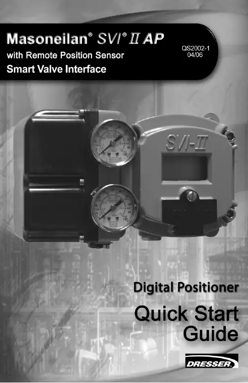
M aso n eilan*S V I*II A P 定位器作业指导书编制:周利鹏审核:王振辉储运公用成品油班组SVI II AP定位器作业指导书1、工作原理SVI II AP是智能电气定位器,它从控制器接收4-20mA电气位置设定点信号并与阀门位反馈传感器比较位置设定点输入信号。
位置设定点和位置反馈之间的差异通过位置控制算法分析计算输出为I/P转换器设定伺服信号。
I/P的输出压力由驱动执行机构的气动气路放大器放大。
一旦设定点和阀门位反馈之间的误差在范围之内,对伺服信号不进行其它纠正,以保持阀位。
阀门定位器外观如图1-1所示。
1-1 SVI II AP2、电气模块接线端子板如图2-1所示。
2-1 接线端子图3、操作按钮本地按钮都位于铰链保护盖后面,显示窗口的正下方。
用一字螺丝刀将中间的螺丝拧开,将黑色盖子掀起,有三个银色按钮分别是‘*’(选择)、‘-’(向后)、‘+’(向前)如图(3-1)3-1 SVI II AP显示屏及操作按钮三个按钮执行以下功能:左按钮:标记为*,允许您选择或接受当前显示的值或参数选项。
中间按钮:标记为-,允许您通过菜单结构返回上一个菜单项目,或者减少数字显示屏上当前显示的值。
当用于减小显示值时,长按按钮就会使值以更快速度减小。
右键按钮:标记为+,允许您通过菜单结构进入下一个菜单项目,或者增加数字显示屏上当前显示的值。
当用于增加显示值时,长按按钮就会使值以更快速度增加。
4、NORMAL 运行模式和 MANUAL 模式菜单当离开NORMAL模式进入MANUAL模式时,阀门处于它离开NORMAL时所处的最后位置。
在MANUAL模式下,设备不会对4-20 mA的信号作出响应。
但是,SVI II AP设备仍然可以对HART命令作出响应,包括定位阀门的HART命令。
当你从NORMAL运行模式菜单切换到VIEW DATA或VIEW ERR菜单,阀门仍然处于NORMAL 模式,并且仍然对4-20mA信号作出响应。
梅索尼兰调节阀调试方法:
SVI1000定位器简明使用方法
定位器上共有四个按键从上往下,1.为定位器定位器全开位整定按键:2.为定位器行程调节按键(一般不用)3为定位器自动整定按键:4为取消按键。
调试方法:按下第一个按键,当它旁边的绿灯闪烁后,在2~7秒内松开按键(超时或时间不够将自动取消操作),定位器自动找阀门全开和全关位,完成后4个指示灯依次闪烁。
阀门自动调整如第一步完成后4个指示灯会依次闪烁定位器调试完成。
反馈应在阀门完成整定后,重新设定,五点(4、、12、16、20mA )
梅索尼兰调节阀调试方法:将HART375手操器连到阀门定位器上后,启动HART375进入MANUAL模式→Calibration Menu→Tuning→AutoTune,然后定位器开始自检,待自检完毕后,退出Calibration Menu模式,进入Normal
模式即可下面举出几个具体列子: Z 7 M" a2 l: Z. G1.阀门反馈不正常解决方法:启
动HART→进入
MANUAL模式→Calibration Menu→Range→Autostops5 Y0 H' \; V1 l; r# `/ a
运行结束后,退出Calibration Menu
模式,进入Normal模式即可9 H( s5 Q. a2 L
Calibration Menu
模式,进入Normal模式即可不动作W. j! q+ e' E9 Y7 t' J( n7 I9 [以下几个方面检查检查阀门是否送电,是否有气源和指令线是W4 o9 {0 j2 u% ?( M" 2)否阀门在手动位置3)是否用HART375调试时打到MANUAL模式,调N式。
常见十二种定位器,调试步骤阀门定位器是控制阀的主要附件,它将阀杆位移信号作为输入的反馈测量信号,以控制器输出信号作为设定信号,进行比较,当两者有偏差时,改变其到执行机构的输出信号,使执行机构动作,建立了阀杆位移量与控制器输出信号之间的一一对应关系。
本文重点讲解常见定位器调试步骤,帮助仪表人轻松掌握各类定位器。
一阀门定位器的原理、作用阀门定位器是控制阀的主要附件。
它将阀杆位移信号作为输入的反馈测量信号,以控制器输出信号作为设定信号,进行比较,当两者有偏差时,改变其到执行机构的输出信号,使执行机构动作,建立了阀杆位移量与控制器输出信号之间的一一对应关系。
因此,阀门定位器组成以阀杆位移为测量信号,以控制器输出为设定信号的反馈控制系统。
该控制系统的操纵变量是阀门定位器去执行机构的输出信号。
(1)用于对调节质量要求高的重要调节系统,以提高调节阀的定位精确及可靠性。
(2)用于阀门两端压差大(△p>1MPa)的场合。
通过提高气源压力增大执行机构的输出力,以克服液体对阀芯产生的不平衡力,减小行程误差。
(3)当被调介质为高温、高压、低温、有毒、易燃、易爆时,为了防止对外泄漏,往往将填料压得很紧,因此阀杆与填料间的摩擦力较大,此时用定位器可克服时滞。
(4)被调介质为粘性流体或含有固体悬浮物时,用定位器可以克服介质对阀杆移动的阻力。
(5)用于大口径(Dg>100mm)的调节阀,以增大执行机构的输出推力。
(6)当调节器与执行器距离在60m以上时,用定位器可克服控制信号的传递滞后,改善阀门的动作反应速度。
(7)用来改善调节阀的流量特性。
(8)一个调节器控制两个执行器实行分程控制时,可用两个定位器,分别接受低输入信号和高输入信号,则一个执行器低程动作,另一个高程动作,即构成了分程调节。
二阀门定位器的分类1、阀门定位器按输入信号分为气动阀门定位器、电-气阀门定位器和智能阀门定位器。
(1)气动阀门定位器的输入信号是标准气信号,例如,20~100kPa气信号,其输出信号也是标准的气信号。

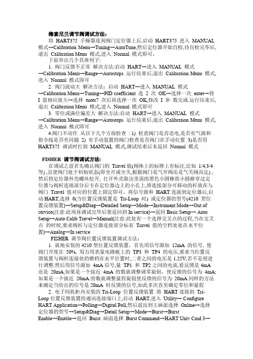
梅索尼兰调节阀调试方法:将HART375 手操器连到阀门定位器上后,启动HART375 进入MANUAL 模式→Calibration Menu→Tuning→AutoTune,然后定位器开始自检,待自检完毕后,退出Calibration Menu 模式,进入Normal 模式即可。
下面举出几个具体列子:1. 阀门反馈不正常解决方法:启动HART→进入MANUAL 模式→Calibration Menu→Range→Autostops 运行结束后,退出Calibration Menu 模式,进入Normal 模式即可2. 阀门波动大解决方法:启动HART→进入MANUAL 模式→Calibration Menu→Tuning→PID coefficient 选2 次OK→选择一次entet→将I 值相应放大→选择enter7 次后再选择一次OK,修改I 参数完成.运行结束后,退出Calibration Menu 模式,进入Normal 模式即可3. 零位或满位偏差大解决方法:启动HART→进入MANUAL 模式→Calibration Menu→Range→Autostops 运行结束后,退出Calibration Menu 模式,进入Normal 模式即可4.阀门不动作从以下几个方面检查: 1) 检查阀门是否送电,是否有气源和指令线是否有问题2) 有手动装置的阀门检查是否阀门在手动位置3)是否用HART375 调试时打到MANUAL 模式,调试结束后未返回Normal 模式FISHER 调节阀调试方法:在调试之前首先确认阀门的Travel值(阀体上的标牌上有标注,比如1/4,3/4 等) ,且使阀门处于初始状态(即全开或全关,根据阀门是气开阀还是气关阀而定) ,然后将定位器外壳螺丝松开, 打开外壳取出里面的黑色小圆棒将小圆棒穿过定位器与阀杆连接部分后卡在定位器边上的小孔上,将连接部分可移动的杆放在与阀门Travel 值对应的位置上固定即可,将信号源和HART连接到定位器后,启动HART,选择0(当位置反馈装置是Tri-Loop 时) 或定位器的型号(4210 型位置反馈装置)→Setup&Diag→Detailed Setup→Mode→Instrument Mode→Out of service(注意:此项再调试完毕后要返回到In service)→返回Basic Setup→ Auto Setup→Auto Calib Travel→Manual(注意:此处有一个选择交叉点的过程,当在交叉点的时候,要求阀杆与定位器连接部分标有Travel 值的空档处处在水平位置)→Analog→In serviceFISHER 调节阀位置反馈装置调试方法:1. 就地安装的4210型位置反馈装置,首先用信号源加12mA 的信号, 使阀门开度在50%, 用万用表量电路板上的TP3 和TP4 的电压,要求当位置反馈装置与阀杆连接处的横档在水平位置时,二者之间的电压是1.25V,若不是则进行调整.然后用信号源加4mA信号,量TP1 和TP2之间的电流,看反馈是4mA 还是20mA,如果是一个接近4mA的数就调整调零旋钮,使反馈的信号为4mA;如果是一个接近20mA的数就调整量程旋钮使反馈的信号为20mA.同样的方法来确定当给出的信号是20mA 时反馈的信号,如此多次直至确定零位和量程2. 电子间机柜内安装的Tri-Loop 位置反馈装置将HART连接到Tri-Loop位置反馈装置的通讯连接端口上,启动HART,进入Utility→ Configure HART Application→Polling→Digital Poll,然后退出到主画面选择Online→选择定位器的型号→Setup&Diag→Detail Setup→Mode→Burst→BurstEnable→Enable→返回Burst 画面选择Burst Command→HART Univ Cmd 3→返回到主画面后选择Online→"1"(指Trip-Loop)→Device Setup→BasicSetup→Configure Channels→Configure CH1→将Burst Variable 的类型改为"QV"Units 设为,"%"LRV 设为,"0",URV 设为"100",CH1 Enabled 设为"YES"然后保存即可.瑞基调门调试方法:瑞基调门调试是使用遥控器来调试的, 使用遥控器对中液晶显示屏按"┙"输入口令"000"进入一级设定菜单, 在一级设定菜单里主要是确定阀门的开关限位, 此时可手动将阀门打到全开(或全关)位置,然后使用遥控器按"↓"选择"打开限位"(或关闭限位) ,按"┙"进入,然后确定保存即可.之后退回主菜单,进入二级设定菜单,在二级菜单下主要是设定输入信号的量程,选择进入模拟信号量程项,选择20mA;然后将阀门打到就地控制状态用信号源加一个4mA 的信号,设定为低限阀位,加20mA 信号设为高限阀位保存即可! 此外可以使用遥控器来调整阀门的力矩,开关方向,保护方式等,具体情况根据显示屏显示选项操作即可西门子定位器调试方法:1.用定位器显示窗口下方的'+'和'-'两个按键, 使执行机构运动, 看整个机构能否自由走满行程.2.让执行器运动到行程的中间位置(直行程的反馈杆处于水平位置) ,就可以进行初始化了. 注:当你按住其中一个键的同时再按另一个键可以加快执行机构的动作.3.按功能键(小手形)5 秒后就可以进行参数设置.4.SIEMENS 定位器共有36 组参数, 可以根据现场的实际情况进行设置. 用'+'和'-' 键可以在一组参数中进行选择, 选择完后可以按一下功能键进入第二组参数的设置, 若上一个参数设置有误,可以按功能键同时按'-'键,回到上一个参数再进行设置.5.在这些参数中有几个是经常用到的. 1YFCT (执行器类型) :直行程选WAY,角行程选TURN. 2YAGL (额定反馈角度) :一般情况下,直行程设置成33,角行程90. 7SDIR: 给定方向上升RISE,给定方向下降FALL 38YDIR (操作变量方向显示) :上升RISE,下降FALL 同时改变SDIR 和YDIR 这两组参数可改变执行器动作方向. 55PRST 预设置(工厂设置) :当重新调试时,先进入55 项,长按+键 5 秒,直到显示ocay,说明已经恢复到工厂设置5.开始初始化时执行器必须处于行程的中间位置.6.参数设置完毕后用功能键切换到第四个参数,显示为'4.INIT',按住'+'键约5 秒定位器就自动进行初始化了.7.初始化一共分为5 步. 1)决定动作方向. 2)检查执行机构行程和零点. 3)确定执行机构上下动作时间. 4)确定最小的定位增量. 5)最佳的瞬时响应.8.当初始化完成时屏幕上显示"FINISH"按一下功能键显示"4.INIT".9.按功能键5 秒后,当屏幕显示有变化时松手,此时定位器处于手动模式,再按一下功能键定位器处于自动模式.10.初始化结束后定位器即进入正常工作状态.。
阀门调试梅索尼兰是一种智能式的定位器,对该种气动阀的调试,首先对控制回路查线和接线方式确认,再次对仪表管道进行吹扫。
注意事项:在进行设置时必须从信号源输入4~20mA电流信号或者从HART(数字通信协议)输入,操作电源来自于4~20mA电流信号或者是12/24VDC电压等多支路供应。
当SVI阀门调节器或控制器没有按钮或者没有显示,如果要进行系统设置或校验,则必须用HART通信协议或者个人计算机上阀门软件来进行阀门参数设定。
该定位器又分为气开式(正作用式:4mA指令对应全关、20mA指令对应全开)、气关式(反作用式:4mA指令对应全开、20mA指令对应全关)和双气缸(厂家说:出厂是什么参数就是什么不需要更改什么参数)三种型号,梅索尼兰有一个简便操作接口、高精度的阀位执行机构、据有自动设置和调整功能。
所以我们首先要认识阀门的用户接口(interface),梅索尼兰有三个操作按钮,○1左边一个按钮上标有“*”字样,这个按钮允许我们进行选择或者确认被改的参数;○2中间这个按钮上标有“-”字样,这个按键允许我们从下一个菜单移到上一个菜单,或者对所修改的参数进行减操作;○3右边这个按钮上标有“+”字样,这个按键允许我们从上一个菜单移到下一个菜单,或者对所修改的参数进行加操作。
当我们首次调试时,第一个看到的画面是“POS…”,如果要调整该定位器,首先必须从“POS…”切换到手动位置,画面显示的是:“MAN POS”。
当阀门在自动位置时我们可以用以下方法进行切换。
首先按标记为“+”的键,只到阀门显示(→MAN)字样时,按“*”键就可以进入手动状态,在手动状态时阀门应显示(MAN POS)字样。
这时如果再按下“*”键,就可以进行手动操作该阀门。
如果想切换到自动位置时,只要该定位器显示(MAN POS)字样时,表示阀门现为手动状态。
这时我们只有按下“+”键,只到显示(→OPER)字样,这时按“*”键,阀门将会自动进入自动状态。
梅索尼兰SVI定位器在核电厂应用及其常见故障发表时间:2018-06-11T11:54:31.147Z 来源:《电力设备》2018年第3期作者:王俊[导读] 摘要:本文以梅索尼兰SVI智能定位器在核电厂汽机旁路系统应用为例,介绍了SVI智能阀门定位器的结构、性能特点、调试方法及常见的故障现象和解决方法,为以后检修工作提供参考。
(中广核核电运营有限公司广东深圳 518034)摘要:本文以梅索尼兰SVI智能定位器在核电厂汽机旁路系统应用为例,介绍了SVI智能阀门定位器的结构、性能特点、调试方法及常见的故障现象和解决方法,为以后检修工作提供参考。
关键词:SVI智能定位器;故障现象;解决方法概述阀门定位器是气动调节阀的关键附件之一,他直接影响调节阀的可用性。
随着工业智能化的发展,微电子技术在阀门定位器的应用,使智能阀门定位器性能和功能有了大的进步。
智能阀门定位器与机械式比较有着显著的优点:校验方便、精度高等。
但是在复杂的环境下,智能定位器也出现过一些问题,本文以核电厂汽机旁路系统应用为例,介绍SVI定位器在系统的应用及其原理、校验方法和常见故障现象。
1 智能定位器在系统中的应用在核电厂中,当反应堆功率与汽机负荷不一致时,汽机旁路排放系统通过把多余的蒸汽排向冷凝器、除氧器和大气为反应堆提供一个“人为”的负荷,从而避免核蒸汽供应系统中温度和压力超过保护阈值,确保电站的安全。
汽机旁路排放系统的排放阀使用气动调节阀,由于该系统在投运时现场温度较高、管道振动大,为了提高可靠性,在的核电厂内使用了分体式SVI智能阀门定位器控制旁路蒸汽排放。
2 智能定位器工作原理SVI系列智能阀门定位器采用非接触阀位传感器和在微处理器板进行定位控制,并具有诊断功能,通过HART通信实时性能监视和获取数据分析有效开展了调节阀预测性维护。
如图1: SVI智能定位器的原理图,该智能定位器为二线制电流回路供电,输入控制信号4-20mADC+HART,当阀门定位器正确安装到控制阀,输入控制信号和气源接通后,电子模块的微处理器开始读取输入控制信号和阀位传感器信号,并进行比较运算,对两者的偏差按PID算法处理,输出I给喷嘴挡板结构的I/P电气转换器的电磁线圈,引起喷嘴挡板间隙改变,进而变为相对应的前置气信号PI,在经气动放大器放大,使气动输出变化,加到执行机构上驱动阀杆位移到设定位置。
WarrantyItems sold by Dresser® are warranted to be free from defects in materials and workmanship for a period of one year from the date of shipment provided said items are used according to Dresser recommended usages. Dresser, Inc. reserves the right to discontinue manufac-ture of any product or change product materials, design or specifications without notice. This instruction manual applies to the following instruments and approved software: SVI ® II AP Positioner and ValVue® software.The SVI II AP series positioners are warranted for use only with interface software approved by Dresser Inc. Consult Masoneilan Dresser factory locations for approved software listing.About this GuideThis Quick Start Guide applies to the following instruments and approved software: SVI II AP -2 through SVI II AP-3- with Firmware version 3.1.1- with ValVue® version 2.4 or greater- with AMS® ValVue® SNAP-ON® version 2.4 or greater- with Model HH375 HART® Communicator with DD published for SVI II AP- (Masoneilan Device type 202, 0, 00CA)The information in this manual is subject to change without prior notice.The information contained in this manual, in whole or part, shall not be transcribed or copied without Masoneilan’s written permission.In no case does this manual guarantee the merchantability of the positioner or the software or its adaptability to a specific client needs.Please report any errors or questions about the information in this manual to your local supplier or visit .CopyrightAll software is the intellectual property of Dresser, Inc.The complete design and manufacture is the intellectual property of Dresser, Inc. Masoneilan®, FVP®, SVI®, and ValVue®are registered trademarks of Dresser, Inc. All information contained herein is believed to be accurate at the time of publication and is subject to change without notice.Copyright 2006 by Dresser, Inc. All rights reserved.PN 055201-167 REV BThis section provides safety information including safety symbols thatare used on the SVI II AP and the safety symbol definition. Important - Please Read Before Installation!Safety Symbols SVI II AP instructions contain DANGER, WARNING, and CAUTION labels and Notes, where necessary, to alert you to safety related or other important information. Read the instructions carefully before installing and maintaining your instrument. DANGER and WARNING hazards are related to personal injury. CAUTION hazards involve equipment or property damage. Operation of damaged equipment can, under certain operational conditions, result in degraded process system performance that can lead to injury or death. Total compliance with all DANGER, WARNING, and CAUTION notices is required forsafe operation.This is the safety alert symbol. It alerts you to potential personal injury hazards. Obey all safety messages that follow this symbol to avoidpossible injury or death.Indicates a potentially hazardous situation, which if not avoided couldresult in death or serious injury.Indicates a potentially hazardous situation, which if not avoided couldresult in serious injury.Indicates a potentially hazardous situation, which if not avoided could result in minor or moderate injury.Safety InformationMasoneilan Dresser SVI II AP Quick Start Guide When used without the safety alert symbol indicates a potentiallyhazardous situation, which if not avoided could result in property damage.Note:Indicates important facts and conditions.SVI II APProductSafety The SVI II AP positioner is intended for use with industrial compressed air or, natural gas systems only. Ensure that an adequate pressurerelief provision is installed when the application of system supplypressure could cause peripheral equipment to malfunction. Installationmust be in accordance with local and national compressed air andinstrumentation codes.Products certified as explosion proof or flame proof equipment or foruse in intrinsically safe installations MUST BE :Installed, put into service, used and maintained incompliance with national and local regulations andin accordance with the recommendations containedin the relevant standards concerning potentiallyexplosive atmospheres.Used only in situations that comply with the certifi-cation conditions shown in this document and afterverification of their compatibility with the zone ofintended use and the permitted maximum ambienttemperatureInstalled, put into service and maintained by quali-fied and competent professionals who have under-gone suitable training for instrumentation used inareas with potentially explosive atmospheres. Before using these products with fluids other than air or for non-industrial applications, consult Dresser, Inc. This product is notintended for use in life support systems.Under certain operating conditions, the use of damaged instrumentscould cause a degradation of the performance of the system which maylead to personal injury or death.Use only genuine replacement parts which are provided by themanufacturer, to guarantee that the products comply with the essentialsafety requirements of the European Directives mentioned on the frontcover.Changes to specifications, structure, and compo-nents used may not lead to the revision of this man-ual unless such changes affect the function andperformance of the product.ContentsSafety Information. . . . . . . . . . . . . . . . . . . . . . . . . . . . . . . . . . . . . iSafety Symbols . . . . . . . . . . . . . . . . . . . . . . . . . . . . . . . . . . . . . . . . . . . . i SVI II AP Product Safety. . . . . . . . . . . . . . . . . . . . . . . . . . . . . . . . . . . . ii Section 1Installation and Set Up . . . . . . . . . . . . . . . . . . . . . . .1 Introduction. . . . . . . . . . . . . . . . . . . . . . . . . . . . . . . . . . . . . . . . . . . . . . 1 Using the Quick Start Guide. . . . . . . . . . . . . . . . . . . . . . . . . . . . . . . . . 2Mounting the SVI II AP . . . . . . . . . . . . . . . . . . . . . . . . . . . . . . . . . . . . . 3 Necessary Precautions . . . . . . . . . . . . . . . . . . . . . . . . . . . . . . . . . . . .4Installing the SVI II AP Remote Position Sensor . . . . . . . . . . . . . . . . 4 Installation Procedure . . . . . . . . . . . . . . . . . . . . . . . . . . . . . . . . . . . . . .5Connecting the Tubing and Air Supply. . . . . . . . . . . . . . . . . . . . . . . . 7 Single Acting Positioner . . . . . . . . . . . . . . . . . . . . . . . . . . . . . . . . . . . . .8 Double Acting Positioner . . . . . . . . . . . . . . . . . . . . . . . . . . . . . . . . . . . .9 Connecting the Air Supply . . . . . . . . . . . . . . . . . . . . . . . . . . . . . . . . . . .9 Wiring the SVI II AP. . . . . . . . . . . . . . . . . . . . . . . . . . . . . . . . . . . . . . . 10 Connecting to the Control Loop . . . . . . . . . . . . . . . . . . . . . . . . . . . . . .10 Wiring Guidelines . . . . . . . . . . . . . . . . . . . . . . . . . . . . . . . . . . . . . . . .10 SVI II AP Setups . . . . . . . . . . . . . . . . . . . . . . . . . . . . . . . . . . . . . . . . . 11 Grounding Practices . . . . . . . . . . . . . . . . . . . . . . . . . . . . . . . . . . . . . .12 Compliance Voltage in Single Drop Current Mode . . . . . . . . . . . . . . .12 Verify Wiring and Connections . . . . . . . . . . . . . . . . . . . . . . . . . . . . . .12Masoneilan Dresser SVI II AP Quick Start GuideSVI II AP Maintenance. . . . . . . . . . . . . . . . . . . . . . . . . . . . . . . . . . . . . 14 Repair . . . . . . . . . . . . . . . . . . . . . . . . . . . . . . . . . . . . . . . . . . . . . . . . .14 Tools Needed for Cover Replacement . . . . . . . . . . . . . . . . . . . . . . . . .14 Display Cover Removal and Installation . . . . . . . . . . . . . . . . . . . . . . .15 Removing the SVI II AP Display Cover . . . . . . . . . . . . . . . . . . . . . . .15 Installing the SVI II AP Display Cover . . . . . . . . . . . . . . . . . . . . . . . .15 Section 2Check Out, Configuration and Calibration . . . . . .17Overview. . . . . . . . . . . . . . . . . . . . . . . . . . . . . . . . . . . . . . . . . . . . . . . . 17Check Out Procedures . . . . . . . . . . . . . . . . . . . . . . . . . . . . . . . . . . . . 17 Physical Inspection . . . . . . . . . . . . . . . . . . . . . . . . . . . . . . . . . . . . . . .17 Actuator, Linkages, or Rotary Adapter . . . . . . . . . . . . . . . . . . . . . . .17 Verify Mounting and Linkage Adjustment . . . . . . . . . . . . . . . . . . . . .18 Checking the Magnet . . . . . . . . . . . . . . . . . . . . . . . . . . . . . . . . . . . .18 Performing a Visual Inspection . . . . . . . . . . . . . . . . . . . . . . . . . .18 Using ValVue 2.4 to Check Magnet Position . . . . . . . . . . . . . . . . . . . .19 Checking the Air Supply . . . . . . . . . . . . . . . . . . . . . . . . . . . . . . . . . . .20 Checking the Electronic Module Connections . . . . . . . . . . . . . . . . . . .20 Making Connections to the Terminal Board . . . . . . . . . . . . . . . . . . . . .22 Operational Checkout. . . . . . . . . . . . . . . . . . . . . . . . . . . . . . . . . . . . . 22 Connecting to the Current Source . . . . . . . . . . . . . . . . . . . . . . . . . . . .22 Pushbutton Locks and Configuration-Lock Jumper . . . . . . . . . . . . . . .23 Hardware Configuration Lock . . . . . . . . . . . . . . . . . . . . . . . . . . . . . .23 Powering Up the SVI II AP . . . . . . . . . . . . . . . . . . . . . . . . . . . . . . . . .23 Configuration. . . . . . . . . . . . . . . . . . . . . . . . . . . . . . . . . . . . . . . . . . . . 24 ValVue 2.4 Software . . . . . . . . . . . . . . . . . . . . . . . . . . . . . . . . . . . . . .24 ValVue 2.4 Lite . . . . . . . . . . . . . . . . . . . . . . . . . . . . . . . . . . . . . . . . .24 System Requirements . . . . . . . . . . . . . . . . . . . . . . . . . . . . . . . . . . .25 ValVue 2.4 Full Trial Version . . . . . . . . . . . . . . . . . . . . . . . . . . . . . . .25 Pushbuttons and Local Display . . . . . . . . . . . . . . . . . . . . . . . . . . . . . .25 Pushbuttons . . . . . . . . . . . . . . . . . . . . . . . . . . . . . . . . . . . . . . . . . . . . .26 Configuration with Pushbuttons . . . . . . . . . . . . . . . . . . . . . . . . . . . . . .27 Viewing Configuration Data . . . . . . . . . . . . . . . . . . . . . . . . . . . . . . .27 Viewing Status Messages . . . . . . . . . . . . . . . . . . . . . . . . . . . . . . . . . .27 VIEW DATA Settings . . . . . . . . . . . . . . . . . . . . . . . . . . . . . . . . . . . . . .28Calibration . . . . . . . . . . . . . . . . . . . . . . . . . . . . . . . . . . . . . . . . . . . . . . 28 Auto Tune . . . . . . . . . . . . . . . . . . . . . . . . . . . . . . . . . . . . . . . . . . . . .29 Check-out with a HART Handheld Communicator. . . . . . . . . . . . . . . .31 Appendix A Specifications and References . . . . . . . . . . .A-1 Physical and Operational Specifications . . . . . . . . . . . . . . . . . . . . A-1 Hazardous Location Installation . . . . . . . . . . . . . . . . . . . . . . . . . . . A-7Installation and Set Up1Introduction The SVI® II AP (Smart Valve Interface) is the next generation ofMasoneilan’s intelligent digital valve positioners. The SVI II AP is acompact, industrial tough, high performance, digital valve positionerthat combines a local display with remote communication anddiagnostic capabilities. The SVI II AP is available with options neededto fulfill virtually all application requirements and communicates usingthe HART® protocol. The SVI II AP offers:Extreme AccuracyExtreme ReliabilityExtreme Digital PrecisionAutomated Valve CommissioningPrecise, Quick, Responsive Control of ValvePositionSophisticated Valve DiagnosticsFigure 1SVI II APSVI II AP Cover SVI II AP AssembledElectronicsModule Pneumatic Train and Cover (I/P Module, Relay)ManifoldRelayI/PMasoneilan Dresser SVI II AP Quick Start GuideFigure 2SVI II AP ComponentsUsing the Quick Start GuideThe SVI II AP Quick Start Guide is intended to help an experiencedField Engineer install, setup, and calibrate an SVI II AP in the mostefficient manner possible. This document provides basic installationand setup instructions and is not intended to replace the in-depthinformation contained in the SVI II AP Instruction Manual EW2002-AP .If you experience problems that are not documented in this guide referto the Masoneilan SVI II AP Instruction Manual EW2002-AP , call yourlocal Masoneilan representative, or go to . Salesoffices are listed on the last page of this documentThe steps necessary to complete the SVI II AP installation and softwaresetup are outlined in Table 1 below. Table 1 SVI II AP Installation Steps Step No.Procedure Reference 1Attach mounting bracket to the actuator.See page 3 for rotary valve and reciprocating valve instructions.2Install the SVI II AP magnetic assembly (rotary valves only).See page 3 for instructions.3Assemble the SVI II AP on thebracket that is mounted to the valveactuator.See page 3 for rotary valve and reciprocating valve instructions.Installation and Set Up Mounting the SVI II AP Failure to adhere to the requirements listed in this manual may causeloss of life and property.Before installing, using, or carrying out any maintenance tasksassociated with this instrument, READ THE INSTRUCTIONSCAREFULLY. (Refer to “Hazardous Location Installation” onpage A-7 of this guide for detailed instructions.)Mounting the SVI II AP This guide provides installation instructions for mounting an SVI II AP on both rotary and reciprocating actuated valves. The mounting process can be broken down into the following:Attach the mounting bracket to the actuator.Install the magnetic assembly.Assemble the SVI II AP on the mounting bracket. Note:The SVI II AP should be mounted with the conduit connections down in order to facilitate drainage of condensate from the con-duit.4Install the Remote Position Sensor, ifnecessary.See page 4 for instructions.5Connect the pneumatic tubing to theSVI II AP.See page 7 for instructions.6Connect the air supply to the SVI IIAP.See page 9 for instructions.7Connect the positioner to the HARTControl Loop segment by installingthe SVI II AP wiring.See page 10 for instructions.8Configure/calibrate using ValVue.2.4See page 24 and page 28 forinstructionsConfigure/calibrate using a HART Hand Held Communicator See page 31 for instructions.Table 1 SVI II AP Installation StepsStep No.Procedure ReferenceMasoneilan Dresser SVI II AP Quick Start Guide Necessary PrecautionsTo avoid injury or the process being affected when installing orreplacing a positioner on a control valve, ensure that:If the valve is located in a hazardous area makesure the area has been certified as “safe” or that allelectrical power to the area has been disconnectedbefore removing any covers or disconnecting anyleads.Shut off air supply to the actuator and to any valvemounted equipment.Ensure the valve is isolated from the process byeither shutting off the process or using bypassvalves for isolation. Tag shutoff or bypass valves toguard against a “turn-on” while work is in progress.Bleed air from actuator and check that valve is in itsunenergized position.It is now safe to disconnect and remove any valve mounted equipmentthat is being replaced.For the procedure to mount rotary and reciprocating valves, refer to theMounting Instructions contained in the valve’s Mounting Box kit.Installing the SVI II AP Remote Position Sensor An option that is available for the SVI II AP is the Remote Position Sensor. The Remote Position Sensor, is a remotely mounted position-sensing device, that is connected electrically to an SVI II AP valve positioner. It is used as position feedback in applications where direct mounting of an SVI II AP to a valve actuator is not practical due, typically but not limited to, extreme vibration, heat or radiation.The Remote Position Sensor is a potentiometer located in an enclosure which can be mounted on a valve or damper to indicate stem position when connected to a suitable receiver. There is a three wire connection provided on a screw terminal block to interconnect to the receiving device.The SVI II AP Remote Position Sensor is suitable for installation outdoors in an industrial environment. Mounting kits are provided topermit mounting on a variety of valves.Do not remove the instrument cover or connect to an electrical circuit ina Hazardous Area unless the power is disconnected.Comply with current national and local regulationsfor electrical installation work.Installation and Set Up Installing the SVI II AP Remote Position SensorComply with national and local explosiveatmosphere regulations.Before carrying out any work on the device, poweroff the instrument or make sure that the localeconditions for potentially explosive atmospherepermit the safe opening of the cover.Installation ProcedureFor the Remote Position Sensor installation procedure refer to themounting instructions provided with the Remote Position Sensor.1.Remove the cover from the Remote Position Sensorassembly by turning the cover in a counter-clockwise (fac-ing the cover) direction.2.Connect the Remote Position Sensor to the mountingbracket by inserting four M6 x 20 mm Socket Head CapScrews through the appropriate screws holes (accordingto the valve) on the Remote Position Sensor bracket andusing a 3⁄16 inch Hex Key with tee handle.3.Route the instrument cable from the SVI II AP to theRemote Position Sensor (see Figure 3 on page 6 forinstallation instructions).4.Thread the cable through the conduit at the bottom of theRemote Position Sensor.ing a blade screwdriver, loosen the screws on theterminal block and connect the black, brown and red wiresto the appropriate labelled connectors.6.Tighten the screws.7.Attach the feedback lever to the Remote Position Sensorshaft. From the cover side, the lever should be pointing tothe left for reciprocating valves and to the right for rotaryvalves.8.Place the Remote Position Sensor on the mountingbracket.9.Attach the Remote Position Sensor and secure theturnbuckle to the lever ensuring that the shaft at the rear ofthe Remote Position Sensor is inserted into the valveactuator. (Refer to Table 2 “Remote Position SensorTurnbuckle Length” below for turnbuckle length.)10.Replace the Remote Position Sensor cover.Table 2 Remote Position Sensor Turnbuckle LengthActuator Size Stroke Turnbuckle Length6 and 100.5 - 0.8 inch 1.25 inch100.5 - 0.8 inch 1.25 inch10>0.8 – 1.5 inch 1.25 inchMasoneilan Dresser SVI II AP Quick Start Guide Figure 3SVI II AP Remote Position Sensor Installation 160.5 - 0.8 inch 2.90 inch 16>0.8 – 1.5 inch 2.90 inch 16>1.5 – 2.5 inch 2.90 inch 230.5 - 0.8 inch 5.25 inch 23>0.8 – 1.5 inch 5.25 inch 23>1.5 – 2.5 inch 5.25 inchStep 1 Connect Drain Wire to Open Terminal Step 2When connecting cable to Remote Position Sensor make sure wire colors match: - Red to Red - Brown to Brown - Black to BlackStep 3Insert Ferrules into “Remote” Terminal Block according to Wire Color SVI II AP Terminal Number Function RedBrownBlack 123 Positive Signal Groundthe chart at the right:Remote Terminal Block123Table 2 Remote Position Sensor Turnbuckle LengthActuator SizeStroke Turnbuckle LengthInstallation and Set Up Connecting the Tubing and Air SupplyConnecting the Tubing and Air Supply The last step in hardware installation for the SVI II AP is to connect the air supply to the positioner. This section describes the process for connecting the tubing and air supply to a single and double actingpositioner.Isolate the valve from the process and disconnect air tubing from the positioner. Disconnect air fully to avoid injury or process damage.1.Install the pneumatic tubing using a regulated, clean,instrument air supply to the air supply port (S←)2.For a single acting actuator - pipe the outbound air fromthe output pressure port (←I) to the valve actuator.3.For a double acting actuator - pipe the air going out ofeach side of valve actuator. Use both output pressure portone (←I) for one side of the actuator and output pressureport two (←II) for the other side of the actuator.4.Connect air supply and actuator outports (1⁄4 inch NPT)Supply pressure for single acting SVI II AP:20 -100 psi (1.4 - 6.9 bar) (138 - 690 kPa)Supply pressure for double acting SVI II AP:20 - 150 psi (1.4 - 10.4 bar) (138 - 1035 kPa)Minimum tubing diameter 1⁄4 inch (6mmx4mm) Note:The SVI II AP Digital Positioner is designed to operate with clean, dry, oil-free, instrument grade air to ANSI-ISA-57.3 1975(R1981) or ISA-S7.3-1975 (R1981) or with a sweet natural gassupply (SVI II AP models SVI II AP-2 through SVI II AP-3).Table 3Dew Point At least 18° F (10° C) below minimum anticipated ambienttemperatureParticulate Matter Filtered to 5 micronsOil Content Less than 1 ppm w/wContaminants Free of all corrosive contaminantsAir Supply RequirementsMasoneilan Dresser SVI II AP Quick Start Guide Single Acting PositionerThe supply and output connections for the SVI II AP, located on bottomof the pneumatic block, are tapped 1⁄4 inch NPT. Output is toward thefront, supply is toward the back. Two pressure gauges, output on top,supply on bottom, are located on the front of the pneumatic block.Maximum allowable air supply pressure to the SVI II AP variesaccording to actuator, valve size, and valve type. See Pressure Droptables in valve specification sheets to determine the correct positionersupply pressure. Minimum supply pressure should be 5 to 10 psi abovemaximum spring pressure but may not exceed the rated actuatorpressure.OutputSupplyFigure 4Air Ports on Single Acting PositionerInstallation and Set Up Connecting the Tubing and Air Supply Double Acting PositionerConnect Output 1, labeled “(←I)” to the inlet port of the actuator andconnect Output 2 labeled “(←II)” to the opposing actuator port (seeFigure 5 below for double acting ports.Output I ConnectorSupply Connector Connector Output IIFigure 5Air Ports on Double Acting PositionerConnecting the Air SupplyAfter the tubing is installed, use the following procedure to connect theair supply.1.Connect a supply of clean, dry compressed air to the filterregulator.2.Turn on the air supply.3.Adjust the filter regulator.4.Supply pressure must be 5 - 10 psi greater than the springrange of the actuator but may not exceed the ratedactuator pressure. Refer to the valve or actuatorinstruction manual.Masoneilan Dresser SVI II AP Quick Start GuideWiring the SVI II AP In order for the SVI II AP to communicate the positioner data the SVI II AP must be physically connected to a HART communication. The procedure below outlines wiring the SVI II AP.Comply with current national and local regulationsfor electrical installation work.Comply with national and local explosiveatmosphere regulations.Before carrying out any work on the device, poweroff the instrument or make sure that the localeconditions for potentially explosive atmospherepermit the safe opening of the cover.Connecting to the Control LoopThe SVI II APpositioner MUST BE grounded according to localregulations. It is important to maintain correct polarity at all times,otherwise the positioner may not operate properly. The SVI II APshould be physically connected to the HART loop using a cablespecified by the HART Communication Foundation. A shielded cableis recommended.To connect the Control Loop to the SVI II AP:1.Connect one end of the cable to the control loop's4 - 20mA output2.Remove the threaded wiring covers on the positioner.3.Connect the other end of the cable to the SVI II AP. Thereare two threaded openings on the positioner. Use theopening with the red plastic insert.4.Maintain polarity + and - respectively.Wiring GuidelinesThis list contains eight guidelines for a successful implementation of DCcurrent signal, DC power, and HART communication to the SVI II AP:pliance voltage at the SVI II AP must be 9 volts at themaximum current of 20 mA.2.Signal to the SVI II AP must be a regulated current in therange 3.2 to 22 mA.3.Controller output circuit must be unaffected by the HARTtones which are in the frequency range between 1200 and2200 Hz.4.Frequency range of the HART tones must have a circuitimpedance of more than 220 Ohms, typically 250 Ohms.5.HART tones may be imposed by the positioner and acommunication device located anywhere on the signalingcircuit.Installation and Set Up Wiring the SVI II AP6.Capacitance of the signaling circuit must not exceed 0.26microfarads or 0.10 microfarads with high seriesresistance.7.Cabling must be shielded to prevent electrical noise thatwould interfere with the HART tones, with the shieldgrounded.8.Signal must be properly grounded in only one place.Note:For details and calculation methods for wiring resistance, andcapacitance and for calculation of cable characteristics pleaserefer to the HART FSK Physical Layer Specification.SVI II AP SetupsTypical system setups are shown in Figure 6 on page 13, GeneralPurpose and Explosion Proof (EEx d) Installation Schematic and Figure7 on page 13, Intrinsically Safe Installation Schematic. The SVI II APpositioner can be located in a general-purpose or hazardous areaprotected by Explosion Proof (EEx d) methods. Wiring diagrams aregeneralized, actual wiring must adhere to Electrical Installation sectionof manual and local electrical codes. The use of a HandheldCommunicator or a HART modem is not permitted in the HazardousArea protected by Explosion Proof (EEx d) methods. In Figure 7 onpage 13 the SVI II AP positioner is located in a hazardous area that isprotected by Intrinsically Safe wiring practices.The SVI II AP requires an electrical input from a 4-20 mA currentsource. The SVI II AP input signal can carry a HART communicationprotocol signal from ValVue 2.4 or greater software and a HARTmodem, or from a HART Hand Held Communicator. Since the processcontrol system, the source of the input signal, is located in a non-hazardous location, setup requires an intrinsic safety barrier be placedbetween the process control system and the SVI II AP. If the SVI II APis located in a hazardous area with Intrinsically Safe protection a barrieris not required for a flameproof installation. Alternatively the systemcan be installed as Explosion Proof ⁄ flameproof. SVI II AP cancommunicate with a remote PC running ValVue software via a modemconnected to the PC's serial or USB port. The PC, which is notintrinsically safe, must be connected to the circuit on the safe area sideof the intrinsic safety barrier if the valve is located in a hazardous area.The SVI II AP can be operated, calibrated, configured, and interrogatedeither by using local pushbutton and display, or by using a PC runningValVue 2.4 software, HART Handheld Communicator, or any registeredHART Host that supports DDs. The HART Handheld Communicator isapproved for Intrinsically Safe use in accordance with FM and ATEXstandards. Read and observe all HHC labelling. The SVI II AP ispolarity sensitive so the positive lead must be connected to the positive(+) terminal and the negative lead to the negative (-) terminal. Reversalof input will not cause damage but the unit will not function.。
常见十二种定位器,调试步骤阀门定位器是控制阀的主要附件,它将阀杆位移信号作为输入的反馈测量信号,以控制器输出信号作为设定信号,进行比较,当两者有偏差时,改变其到执行机构的输出信号,使执行机构动作,建立了阀杆位移量与控制器输出信号之间的一一对应关系。
本文重点讲解常见定位器调试步骤,帮助仪表人轻松掌握各类定位器。
一阀门定位器的原理、作用阀门定位器是控制阀的主要附件。
它将阀杆位移信号作为输入的反馈测量信号,以控制器输出信号作为设定信号,进行比较,当两者有偏差时,改变其到执行机构的输出信号,使执行机构动作,建立了阀杆位移量与控制器输出信号之间的一一对应关系。
因此,阀门定位器组成以阀杆位移为测量信号,以控制器输出为设定信号的反馈控制系统。
该控制系统的操纵变量是阀门定位器去执行机构的输出信号。
(1)用于对调节质量要求高的重要调节系统,以提高调节阀的定位精确及可靠性。
(2)用于阀门两端压差大(△p>1MPa)的场合。
通过提高气源压力增大执行机构的输出力,以克服液体对阀芯产生的不平衡力,减小行程误差。
(3)当被调介质为高温、高压、低温、有毒、易燃、易爆时,为了防止对外泄漏,往往将填料压得很紧,因此阀杆与填料间的摩擦力较大,此时用定位器可克服时滞。
(4)被调介质为粘性流体或含有固体悬浮物时,用定位器可以克服介质对阀杆移动的阻力。
(5)用于大口径(Dg>100mm)的调节阀,以增大执行机构的输出推力。
(6)当调节器与执行器距离在60m以上时,用定位器可克服控制信号的传递滞后,改善阀门的动作反应速度。
(7)用来改善调节阀的流量特性。
(8)一个调节器控制两个执行器实行分程控制时,可用两个定位器,分别接受低输入信号和高输入信号,则一个执行器低程动作,另一个高程动作,即构成了分程调节。
二阀门定位器的分类1、阀门定位器按输入信号分为气动阀门定位器、电-气阀门定位器和智能阀门定位器。
(1)气动阀门定位器的输入信号是标准气信号,例如,20~100kPa气信号,其输出信号也是标准的气信号。
定位器一般操作功能在一般操作中,控制器单元使用设定的4-20MA作为定位器输入信号,数字按顺序显示阀的位置,输入信号和执行器压力,间隔1.5秒,按任何键,会进入如图显示的操作模式菜单.操作模式单有3个选项,1)MAN(将阀打到手动模式,进入手动菜单) 2)EXAMINE(进入检测菜单) 3)OPEN(返回到当前显示的位置,压力,和信号大小),使用按键,可从一个选项进入另一个选项,按*键进入菜单内容.组态参数与可用选项,你可以通过下面的描述来了解按键选项,我们建仪你使用菜单结构图,根据描述的结构来了解.之前注释,在校准前必须完成组态,及组态只有当手动模式下才能完成.菜单内容选项描述单或(双) 选择单或双作用执行机构CTL关(或开) 选择PID控制器功能(关或开) ATO(或ATO) 选择气开或气关的执行器选项线性(或EQUAL50,EQUAL30 选择要求阀特性曲线(线性,等50 快开,自定) %,等30%,快开,自定义,自定义要通过电脑连接输入TS(关或开) 显示设定的紧关点,默认0%PL(关或开) 显示设定阀最底限位点,默认0% PU(关或开) 显示设定阀最高限位点,默认100%英语(或法语) 选择显示语言(英语或法语)步骤调试组态,执行以下步骤1在一般操作模式,按任何键,显示OPEN,按+进入MAN菜单内容2按*移至手动模式,(显示POS MAN),此时阀定位在手动模式.3按+两次移至CONFIG选项.4按*把定位器调至组态模式并显示CONFIGURE菜单.5当单或双按要求显示了,按+进入下一个内容,如果不是,按*进行选择.完成后按+进入下一个内容,(双作用不是当前就能实现的)6在CTL ON(OFF),定位器显示OFF,如果显示ON,按*选择OFF,按+进入下一内容.7在ATO(ATC),如果选项显示正确,按+进入下一内容,如果不是,按*选择另一选项,当完成时,按+进入下一内容.8当线性(或其他曲线),如果按要求显示,按+进入下一内容.如果不是,按*选择其他选项,完成后,按+进入下一内容.如果选择”CUSTOM”,自定义曲线必须通过软件程序输入给阀门,不能通过按钮实现输入.9全关的选项允许用户使用定位器组态在提供满压力(或大气压)时,执行器无论给阀信号都接近于关阀的位置.如果TS选项打开,阀会接近阀被迫全关状态,当TS关(开),如果阀位和显示令人满意的,按+进入下一内容,如果不是,按*改变开/关状态并显示值,然后按+或—增加或减小显示值.(当状态由开到关,没有值显示)当数值设好,按*确认并进入下一内容.10定位器允许用户在组态中设定一个最低限位和最高限位,当操作中打开限位,阀的动作不能低于最低位,也不能高于最高位.(注:这些是软件上停止限制,如果定位器由于任何理由故障,包括电源故障或气路故障,定期位器将不能在限位停止,阀将失去安全,此外,阀上的全开全关按钮避开这个限位控制.如果安全地要求使用限停,机械停止将会被用)当PL关(开),状态和显示值恰当的,按+工作入下一个内容,如果没有,按*改变开/关状态和显示值,然后按+或—来增加或减小显示值(当状态从开改变到关,不显示值),当完成时,按*确认并进入下一内容.11当PU关(开),如果状态和显示值恪恰当的,按+进入下一内容.如果不是,按*改变开/关状态和显示值,然后按+或—号来增加发减小显示值(当状态从开改变到关,不显示值)当值完成时,按*确认并进入下一内容.12定位器显示可用英语或法语.如果语言正确,按+进入下一内容,如果不是,按*选择其他的选项,当设定的语言显示,按+进入下一内容.13在→MAN时,按+移至组态的最前面,或按—返回前一内容,按*离开组态菜单,将返回手动菜单.(显示POS MAN)这就完成了组态部分步骤.14接下来按—移至→CAL继续校准,继续下面的四步. 局部校准注:在运行校准功能前确认组态功能你可以通过校准功能确认定位器产品.输入信号的低高值.执行器压力输出低高值.设定最小最大阀位步骤参考到菜单结构在如图中,邦助了解步骤描述用按钮校准定位器,执行以下步骤。
**Device Setup**(设备安装)1.Mode Normal/Manual/Setup (模式)(普通)/(手动)/(设置)2.Change Mode(更改模式)3.Setup Wizard(安装向导)4.Manual Setup(手动安装)5.Configuration(配置)6.Calibration(校验)missioning Services(试运行)Set Mode Target(设置模式)1.Normal(普通)2.Manual(手动)3.Setup(设置)Air Actiong Configuration(气动配置)1.Skip This Task(忽略)2.Select Air Action(选择气动)Manual Setup(手动设置)1.Mode Setup(模式)(设置)2.Reset Basic Configuration(重设基础配置)3.Configure Wizard(配置向导)4.Find Stops(停止)5.Auto Tune(自动调整)Select Air Action(选择气动)Air To Close(气关)Air To Open (气开)Are you sureABORTOKAllow Override Limits(允许超过限位)Enabled(许可)Disabled(禁止)Select Tight Shutoff(选择关闭密封装置)Enabled(许可)Disabled(禁止)Value(数值)XX.XPressure Units(压力单位)psibarkpaDisplay Language(语言显示)Engish(英文)French(法文)Button Lock Level(按键锁级别)All ENabled(所有启动)NO Config/CalNO Manual(自动)Locked(锁住)Select Air Action(选择气动)Air To Close(气关)Air To Open(气开)Vlve Near Closed Value(阀位闭合值)XX.X(%)Find Valve stops(阀门停止)1.Skip This Task(忽略)2.Run Auto Tune(运行)Auto Tune(自动调整)1.Skip This Task(忽略)2.Run Auto Tune(运行)-9 to +90 Normal Tuning(普通调整)Reset to Factory Defalut(重设出厂状态)1.Skip This Task(忽略)2.Set All Values to Default(设置所有值至出厂状态)Warning(等待)ABORT(终端异常)OKPlease wait(请等待)ABORTOKAggressiveness LevelDELABORTENTER(进入)-9 to +90 Normal Tuning(普通调整)ABCDConfiguration(配置)1.Reset Basic Config and Cal Defaults(重置基本配置和Cal默认值)2.General(常规设置)3.Actuator Type(执行机构类型)4.Positioning(定位)5.Limits/Shutoff(限位/关闭)6.Alarms Setup(警报设置)7.Switches(开关)8.HART(HART)9.Device Info(设备信息)General(常规设置)1.Tag:(标签)2.Descriptor(描述符)3.Message(信息)4.Date(日期)5.Final Asmbly Nbr(仪表装备号)6.LCD Language(液晶屏语言)7.Local Buttons(就地按钮)8.Pressure Units(压力单位)9.Switch positions(开关位置)Actuator Type(执行机构类型)1.Air Action: ATO/ATC2.Type:Single/Double(类型:单/双)Positioning(定位)1.Characterization: Linear/EQ50/EQ30/QO/Camflex(特性) (线性)2.Low Signal: 4.00mA(低信号)3.High Signal : 20.00mA(高信号)4.Bumpless Transfer: Disabled/Enabled(缓冲传输)(禁止)/(许可)5.Allow Override Limits: Disabled/Enabled(允许超过限位) (禁止)/(许可)6.Positions Sensor: Built-in Sensor/Remote(位置传感器)(内置传感器)7.Custom and/or Standard Chaaracterization :(制定或标准特性)Select Cam(选择通用控制阀)Linear(线性)Equal%(30)Equal%(50)Quick Open(快速打开)Custom(自定义)Camflex-Equal%(通用控制阀)Alarms Setup(警报设置)1.Near Close Value:ValueXX.X%(最近关闭值)2.Pos Error: Disabled/Enabled(Pos错误)(禁止)/(许可)3.Pos Error Band :XX.X%(Pos错误频带)4.Pos Error Time :XX.Xs(Pos错误时间提示)Switches(交换机)1.DO Switch 1 Action :(模拟量输出开关1动作)2.DO Switch 1 Normally Open/Close(模拟量输出开关1常开)/(模拟量输出开关1常关)3.DO Switch 2 Action :(模拟量输出开关2动作)4.DO Switch 2 Normally Open/Close(模拟量输出开关2常开)/(模拟量输出开关2常关)Limits/Shutoff(限位/关闭)1.Positions Limit Low: Disabled/Enabled(位置下限)(禁止)/(许可)2.Low Limit: 0.0%(Typical)(低下限)3.Position Limit High: Disabled/Enabled(位置高限位)(禁止)/(许可)4.Limit High: 100.00%(Typical)(高限位)5.Tight Shutoff: Disabled/Enabled(密封关闭)(禁止)/(许可)6.Tight Shutoff Value: XX.X%(Signal)(密封关闭值)(信号)HART1.Poll Addr:0(Typical)(寻址)2.Nbr Of preambles:5(Typical)3.Phys Sign Code:Bell 202 Current(物理符号代付符)4.Device Flags :0X00(设备标志)5.Burst Mode: Off/On(脉冲模式)6.Burst Command :CMD 3(脉冲命令)Manufacturer(厂商)Model(模型)Trans CmdRev(转速转换器)Hardware Rev(转速硬件)Universal CmdRev(通用设备标)Device ID(设备地址)Software Rev(转速软件)FirmwareVersion(固件版本)Calibration(校准)1.Mode:Setup(模式) (设置)2.Change Mode(更改模式)3.Valve Travel(阀门行程)4.Manual Position(手动位置)5.Valve Tuning Data(阀门调整数据)6.Sensors(传感器)7.Reset Cal Factory Defaults(重置Cal工厂默认值)Sensors(传感器)1.Input Current Sensor(输入电流传感器)2.Pressure Sensor(压力传感器)3.Input Calibration diagram(输入标定图)Open Stop Adjustment(开停调整)Enter Value XX.XX%(阀位输入)Valve Travel(阀门行程)1.Mode: Setup2.Change Mode(更改模式)3.Find Stops4.Open Stop Adjustment(开停调整)5.Manual Stops(手动停止)6.Autotune(自动调整)7.Manual Tuning(手动调整)Manual Positioning(手动位置)1.Valve Position X.X %(阀门位置)2.Full Open(全开)3.Full Open(全关)4.Set Position(固定位置)5.Position Bar(位置栏)Enter Value(mA)(输入值)Low Range(范范围)High Range(高范围)Set Manual Stops(手动停止装置)1.Low(低)2.High(高)3.Exit(退出)Aggressiveness LevelDELABORTENTER(输入)-9 to +90 Normal Tuning(普通调整)Bosst(提高)PDpadj(功率)Beta(软件测试)Compens.pas(补偿控制线保护系统)Stroke Time(行程时间)Dead Zone(盲区)ICommissioning Services(试运行)1.Mode : Setup2.Input signal: XX.XXmA(输入信号)3.Valve Position: X.X%(阀门位置)4.Basic Info(基本信息)5.Manual Position(手动位置)6.Position Retransmit(位置重新发送)7.Signal Bar(信号栏)8.Switches(开关)9.Position Bar(位置栏)**NORMAL MODE**(普通模式)1.Mode :Normal2.Input signal: XX.XXmA(输入信号)3.Valve Position: X.X%(阀门位置)4.Manual Setpoint:XX.X%(手动设置)5.Read Pressures(压力读写)6.Device Setup(设备安装)7.Status/ Diagnostics(状态/诊断)**Read Pressures**(压力读写)1.Pressure Unit psi (压力单位 帕)2.Supply Pressure: X.XX(供应压力)梅索475手持通信器SVI-IIAP指南AB CDDevice Info。
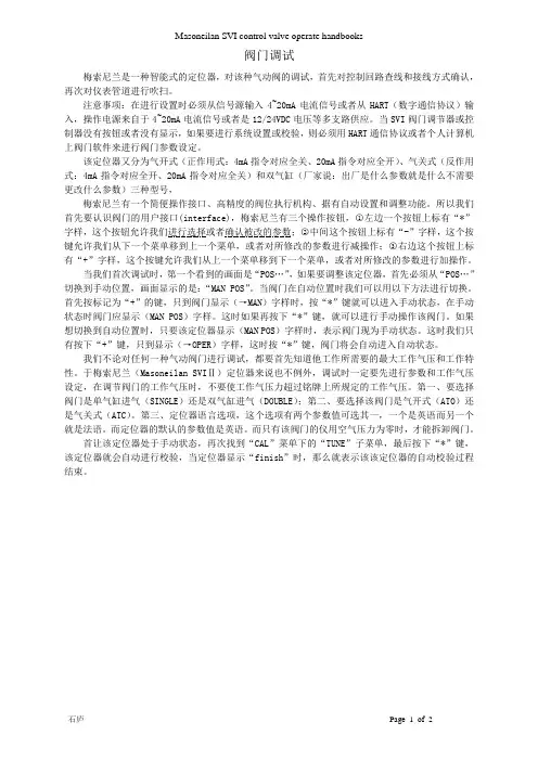
MASONEILAN 定位器说明共2页、第1页MASONEILAN 定位器说明共2页、第2页注:Masoneilan 定位器通上手操器后,打开的是‘正常模式’(NORMAL MODE )主画面,要进入上图第一个画面,必须先进‘手动模式菜单’(MANUAL MODE MENU ),再回退至‘HOME ’,即‘手动模式’(MANUAL MODE )主画面,此画面在调整回讯时有用。
对定位器操作完成后,必须切至‘正常模式’(NORMAL MODE ),否则总控信号不起作用。
回讯不到位调整方法定位器的反馈连接如图1所示:当手操器进入在线‘手动模式’ (MANUALMODE )主画面后,用第3项change pos<->来使阀门100%(选全开则阀门能开多大就开多大)、全关,并在100%、0%阀位时松开‘并紧螺母’,调整‘双头内螺纹螺杆’,使第1项Vavle position 阀位回讯值也为100%和0%,多调几次调好后拧紧‘并紧螺母’。
调完请重新再标定一次。
反馈联杆安装在不同的安装孔会有不同的阀位行程,越往里行程越小,而行程回讯都为100%(可能因为回讯电位器转够一定的角度即100%,阀位不再动作)。
当安装孔动过以后,如果行程不到位,标定是不能把行程标正常的。
回讯与阀位反向调整方法config mune ——setup ——Air to close (气关阀)项目与实际一致的话,用change pos<->把阀门调至全开,再用calibrate mune ——range ——find stops limit 去寻找停止位(输入100%),回讯就会与阀位一致。
注:标定约需10分钟,如果有大的错误如气源没有等,标定会很快终止并提示,如果回讯与阀位反向,标定可能会一直进行下去,标不完,此时要安上面方法调整。
图1:反馈连杆组件图。
经验常用定位器调校方法!看这里阀门定位器按结构分:气动阀门定位器、电气阀门定位器及智能阀门定位器,是调节阀的主要附件,通常与气动调节阀配套使用,它接受调节器的输出信号,然后以它的输出信号去控制气动调节阀,当调节阀动作后,阀杆的位移又通过机械装置反馈到阀门定位器,阀位状况通过电信号传给上位系统。
阀门定位器按其结构形式和工作原理可以分成气动阀门定位器、电-气阀门定位器和智能式阀门定位器。
阀门定位器能够增大调节阀的输出功率,减少调节信号的传递滞后的情况发生,加快阀杆的移动速度,能够提高阀门的线性度,克服阀杆的摩擦力并消除不平衡力的影响,从而保证调节阀的正确定位。
01阀门定位器的分类1、阀门定位器按输入信号分为气动阀门定位器、电气阀门定位器和智能阀门定位器。
(1)气动阀门定位器的输入信号是标准气信号,例如,20~100kPa气信号,其输出信号也是标准的气信号。
(2)电气阀门定位器的输入信号是标准电流或电压信号,例如,4~20mA电流信号或1~5V电压信号等,在电气阀门定位器内部将电信号转换为电磁力,然后输出气信号到拨动控制阀。
(3)智能电气阀门定位器它将控制室输出的电流信号转换成驱动调节阀的气信号,根据调节阀工作时阀杆摩擦力,抵消介质压力波动而产生的不平衡力,使阀门开度对应于控制室输出的电流信号。
并且可以进行智能组态设置相应的参数,达到改善控制阀性能的目的。
2、按动作的方向可分为单向阀门定位器和双向阀门定位器。
单向阀门定位器用于活塞式执行机构时,阀门定位器只有一个方向起作用,双向阀门定位器作用在活塞式执行机构气缸的两侧,在两个方向起作用。
3、按阀门定位器输出和输入信号的增益符号分为正作用阀门定位器和反作用阀门定位器。
正作用阀门定位器的输入信号增加时,输出信号也增加,因此,增益为正。
反作用阀门定位器的输入信号增加时,输出信号减小,因此,增益为负。
4、按阀门定位器输入信号是模拟信号或数字信号,可分为普通阀门定位器和现场总线电气阀门定位器。
培训讲义
本次课课题:梅索尼兰定位器调试学时数:2学时
培训内容:
SVI II型定位器和SVI II AP型定位器在维修和更换安装阀门后要重新进行“阀门行程校验”Find Stop和Auto Tune校验,来确保阀门开度的精度。
下面介绍用HART475校验的具体步骤:
SVI II 型定位器:
1.将定位器安装到阀门,接上正常的电气信号,连接HART475与定位器,进入“normal mode”(正常模式)菜单模式。
2.在“normal mode”(正常模式)菜单下选择第4项“manual mode menu”(手动模式菜单)并进入
3.在“manual mode menu”(手动模式菜单)下选择第3项“calibrate menu” (校验菜单),并进入
4.在“calibrate menu”(校验菜单)下选择第1项“Range”(范围)并进入“choose”(选择)菜单
5.在“choose”(选择)菜单下选择“Auto stops”(自动停止)作定位器快开快关校验
6.完成后返回“calibrate menu”(校验菜单),选择第2项“Tuning”(调谐)并进入“Tuneing choose”(调谐选择)选项菜单
7.在“Tuneing choose”选项菜单下选择第2项“autotune”(自动调谐)自动校验PID
8.完成后按以上步骤返回到初始菜单。
SVI II AP型定位器有三种步骤:
第一种步骤:
1.将定位器安装到阀门,接上正常的电气信号,连接HART475与定位器,建立通讯后,进入菜单第6项“Device Setup”(设备设置)菜单模式。
2. 在“Device Setup”(设备设置)菜单模式进入第2项“change mode”(更改模式),将模式改为第3项“setup”(设置)
3.返回“Device Setup”(设备设置)菜单模式,进入第4项“Manual Setup”(手动设置)选项菜单
4.在“Manual Setup”(手动设置)选项菜单下分别进入第4项“Find Stops”(找到停止)作快开快关校验,完成后返回“Manual Setup”(手动设置)选项菜单
5.在“Manual Setup”(手动设置)选项菜单选择第5项“Auto Tune”(自动调谐)作定位器的PID参数校验
6.校验完毕后返回菜单“change mode”(更改模式)将模式改为”Normal”(正常)初始菜单。
第二种步骤:
1. 菜单第6项“Device Setup”(设备设置)菜单模式选择第3项“Setup Wizard”(设置向导)选项菜单并进入“Air Action Configurartion”(空气动作组态)菜单
2.在“Air Action Configurartion”(空气动作组态)菜单选择第1项“Skip This Task”(跳过)进入“Find Valve Stops”(阀门停止)菜单
3.在“Find Valve Stops”(阀门停止)菜单下选择第2项“Run Auto Stops”(运行自动停止)作定位器全开全关校验,完成后进入“Auto Tune”(自动调谐)菜单
4.在“Auto Tune”(自动调谐)菜单下选择地第2项“Run Auto Tune”(运行自动调谐)作定位器PID参数校验,完成后进入“Reset to Factory Default”(重置为出厂默认)菜单
5.在“Reset to Factory Default”(重置为出厂默认)菜单下选择第1项“Skip This Task”(跳过)返回初始菜单。
6.确认菜单“change mode”(更改模式)将模式改为”Normal”。
第三种步骤:
1.进入菜单选择第6项“Device Setup”(设备设置),在“Device Setup”(设备设置)菜单模式进入第6项“Calibration”(校验菜单)选择“change mode”(更改模式),将模式改为第3项“setup”(设置)后返回“Calibration” (校验菜单)。
2.在“Calibration”(校验菜单)中进入第3项“Valve Ttavel”,然后选择第6项“Auto Tune”作定位器的P I D参数校验。
3.校验完毕后返回菜单“change mode”将模式改为”Normal”
注:SVI II AP定位器用HART375校验时,HART375必须经过升级后才能使用。