各种视频插头插座接口介绍
- 格式:doc
- 大小:225.50 KB
- 文档页数:8
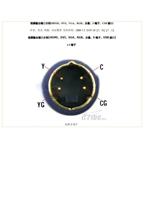
视频输出端口介绍(HDMI、DVI、VGA、RGB、分量、S端子、USB接口)作者:佚名来源:本站整理发布时间:2009-5-3 23:07:10 [收藏] [评论]视频输出端口介绍(HDMI、DVI、VGA、RGB、分量、S端子、USB接口)1.S端子标准S端子标准S端子连接线音频复合视频S端子色差常规连接示意图S端子(S-Video)是应用最普遍的视频接口之一,是一种视频信号专用输出接口。
常见的S端子是一个5芯接口,其中两路传输视频亮度信号,两路传输色度信号,一路为公共屏蔽地线,由于省去了图像信号Y与色度信号C的综合、编码、合成以及电视机机内的输入切换、矩阵解码等步骤,可有效防止亮度、色度信号复合输出的相互串扰,提高图像的清晰度。
一般DVD或VCD、TV、PC都具备S端子输出功能,投影机可通过专用的S端子线与这些设备的相应端子连接进行视频输入。
显卡上配置的9针增强S端子,可转接色差S端子转接线欧洲插转色差、S端子和AV与电脑S端子连接需使用专用线,如VIVO线2.VGA接口DVI接口正在取代VGA,图为DVI转VGA的转接头VGA是Video Graphics Adapter的缩写,信号类型为模拟类型,视频输出端的接口为15针母插座,视频输入连线端的接口为15针公插头。
VGA端子含红(R)、黄(G)、篮(B)三基色信号和行(HS)、场(VS)扫描信号。
VGA端子也叫D-S ub接口。
VGA接口外形象“D”,其具备防呆性以防插反,上面共有15个针孔,分成三排,每排五个。
VGA接口是显卡上输出信号的主流接口,其可与CRT显示器或具备VGA接口的电视机相连,VGA接口本身可以传输VGA、SVGA、XGA等现在所有格式任何分辨率的模拟RGB+HV信号,其输出的信号已可和任何高清接口相貔美。
VGA转DVI线,可用在没有VGA接口的设备上目前VGA接口不仅被广泛应用在了电脑上,投影机、影碟机、TV等视频设备也有很多都标配此接口。
各种接插件类型及识别在电子领域中,接插件是指用于连接电路或设备的插头和插座。
它们可以根据用途和特性进行分类和识别。
下面将介绍各种接插件类型及其识别方法。
1.电源插头和插座:这是用于连接电器设备与电源的插头和插座,常见的有国际通用的两脚插头(如C型、J型)和三脚插头(如NEMA5-15)等。
电源插头和插座通常具有特定形状和大小,以确保正确的配对连接,并且可能有额外的安全功能,如接地插头。
2.通信插头和插座:3.视频/音频插头和插座:用于连接视频和音频设备的插头和插座。
其中最常见的是耳机插头(如3.5mm)和音频/视频插头(如RCA)。
此外,还有HDMI插头、VGA 插头、DisplayPort插头等。
4.数据插头和插座:用于连接数据设备的插头和插座。
最常见的是USB插头和插座,有多种型号,如USB-A、USB-B、Micro USB、USB-C等。
此外,还有FireWire 插头、eSATA插头等。
5.扩展插头和插座:用于扩展设备连接的插头和插座。
最典型的例子是电源延长线,它具有一个插头和一个插座,可以将电源连接延长到较远的位置。
同样,还有USB延长线、音频延长线等。
6.传感器插头:用于连接传感器设备和测量仪器的插头和插座。
传感器插头的类型和形状各异,通常根据具体的传感器应用来设计和识别。
7.电池插座:用于连接电池和电池充电设备的插头和插座。
不同类型的电池有不同的插头和插座设计,以保证正确的连接和充电。
除了以上列举的常见接插件类型,还有许多其他特定的插头和插座,如芯片编程插头、模块连接插头等。
要识别接插件类型,可以根据以下方式进行:1.外观形状:不同类型的接插件通常具有特定的形状和结构,可以根据外观来初步判断其类型。
2.引脚数量和排列:接插件的引脚数量和排列方式也是一个重要的识别依据。
不同类型的接插件具有不同数量和排列的引脚,可通过引脚数量和位置的对比来识别插头和插座。
3.标记和标识:很多接插件上会标有型号、规格或标识,通过阅读这些标记可以找到相应的说明书,进一步确认其类型和用途。
常用视频接口我们经常在家里的电视机、各种播放器上,视频会议产品和监控产品的编解码器的视频输入输出接口上看到很多视频接口,这些视频接口哪些是模拟接口、哪些是数字接口,哪些接口可以传输高清图像等,下面就做一个详细的介绍。
目前最基本的视频接口是复合视频接口、S-vidio接口;另外常见的还有色差接口、VGA 接口、接口、HDMI接口、SDI接口。
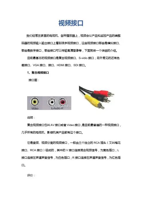
1、复合视频接口接口图:说明:复合视频接口也叫AV接口或者Video接口,是目前最普遍的一种视频接口,几乎所有的电视机、影碟机类产品都有这个接口。
它是音频、视频分离的视频接口,一般由三个独立的RCA插头(又叫梅花接口、RCA 接口)组成的,其中的V接口连接混合视频信号,为黄色插口;L接口连接左声道声音信号,为白色插口;R接口连接右声道声音信号,为红色插口。
评价:它是一种混合视频信号,没有经过RF射频信号调制、放大、检波、解调等过程,信号保真度相对较好。
图像品质影响受使用的线材影响大,分辨率一般可达350-450线,不过由于它是模拟接口,用于数字显示设备时,需要一个模拟信号转数字信号的过程,会损失不少信噪比,所以一般数字显示设备不建议使用。
2、S-Video接口接口图:说明:S接口也是非常常见的接口,其全称是Separate Video,也称为SUPER VIDEO。
S-Video连接规格是由日本人开发的一种规格,S指的是“SEPARATE(分离)”,它将亮度和色度分离输出,避免了混合视讯讯号输出时亮度和色度的相互干扰。
S接口实际上是一种五芯接口,由两路视亮度信号、两路视频色度信号和一路公共屏蔽地线共五条芯线组成。
评价:同AV 接口相比,由于它不再进行Y/C混合传输,因此也就无需再进行亮色分离和解码工作,而且使用各自独立的传输通道在很大程度上避免了视频设备内信号串扰而产生的图像失真,极大地提高了图像的清晰度。
但S-Video仍要将两路色差信号(Cr Cb)混合为一路色度信号C,进行传输然后再在显示设备内解码为Cb和Cr进行处理,这样多少仍会带来一定信号损失而产生失真(这种失真很小但在严格的广播级视频设备下进行测试时仍能发现) 。
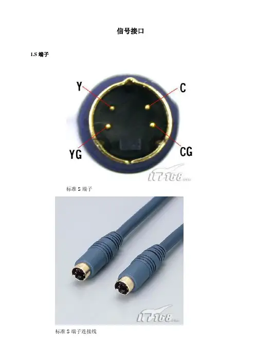
信号接口1.S端子标准S端子标准S端子连接线音频复合视频S端子色差常规连接示意图S端子(S-Video)是应用最普遍的视频接口之一,是一种视频信号专用输出接口。
常见的S端子是一个5芯接口,其中两路传输视频亮度信号,两路传输色度信号,一路为公共屏蔽地线,由于省去了图像信号Y与色度信号C的综合、编码、合成以及电视机机内的输入切换、矩阵解码等步骤,可有效防止亮度、色度信号复合输出的相互串扰,提高图像的清晰度。
一般DVD或VCD、TV、PC都具备S端子输出功能,投影机可通过专用的S端子线与这些设备的相应端子连接进行视频输入。
显卡上配置的9针增强S端子,可转接色差S端子转接线欧洲插转色差、S端子和A V与电脑S端子连接需使用专用线,如VIVO线2.VGA接口DVI接口正在取代VGA,图为DVI转VGA的转接头VGA是Video Graphics Adapter的缩写,信号类型为模拟类型,视频输出端的接口为15针母插座,视频输入连线端的接口为15针公插头。
VGA端子含红(R)、黄(G)、篮(B)三基色信号和行(HS)、场(VS)扫描信号。
VGA端子也叫D-Sub接口。
VGA接口外形象“D”,其具备防呆性以防插反,上面共有15个针孔,分成三排,每排五个。
VGA接口是显卡上输出信号的主流接口,其可与CRT显示器或具备VGA接口的电视机相连,VGA 接口本身可以传输VGA、SVGA、XGA等现在所有格式任何分辨率的模拟RGB+HV信号,其输出的信号已可和任何高清接口相貔美。
VGA转DVI线,可用在没有VGA接口的设备上目前VGA接口不仅被广泛应用在了电脑上,投影机、影碟机、TV等视频设备也有很多都标配此接口。
很多投影机上还有BGA输出接口,用于视频的转接输出。
3.分量视频接口3RCA连接线标准的3RCA线头分量视频接口也叫色差输出/输入接口,又叫3RCA。
分量视频接口通常采用YPbPr和YCbCr两种标识。
分量视频接口/色差端子是在S端子的基础上,把色度(C)信号里的蓝色差(b)、红色差(r)分开发送,其分辨率可达到600线以上,可以输入多种等级讯号,从最基本的480i到倍频扫描的480P,甚至720P、1080i等等。
各种视频音频输出端口图片说明要点在现代科技时代,电视、音响、电脑等家用电器中,往往需要连接各种不同的音视频输出端口以获取更好的使用效果。
了解这些端口的名称和特点是使用这些设备的必要条件。
本文介绍了常见的视频和音频输出端口,并附带了图片说明,以方便读者更好地了解它们的区别和用途。
HDMI端口HDMI(高清晰度多媒体接口)是一种全数字接口,可以传输高品质的音视频信号。
HDMI接口通常用于连接高清电视、高清播放器、高清游戏机和其他高清设备。
它被认为是目前最常用的视频和音频输出端口之一。
HDMI端口HDMI接口的最大特点是数字信号传输。
这种全数字传输优势在于可以避免信号在传输过程中受到干扰等传统线路问题,从而更好地保证信号的高品质传输。
HDMI接口还支持高达4K的分辨率,因此适用于连接高清电视。
DisplayPort端口DisplayPort是一种数字音视频连接的标准,也是一种全数字接口。
和HDMI接口一样,DisplayPort支持高分辨率的图像输出。
DisplayPort接口主要用于连接电脑机箱,但它也是一种通用接口,可以适用于连接多种高清设备。
DisplayPort端口优点是DisplayPort支持高达8K的分辨率,为连接大屏幕电视的电脑带来了无限的可能性。
此外,DisplayPort还支持多个显示器的连接,可以连接多个电脑显示器,从而更方便地实现较大的办公环境。
DVI端口DVI(数字视频接口)是一种数字视频输出端口。
DVI通常用于连接计算机显卡和电视屏幕。
尽管DVI接口在传输数字信号方面较为可靠,但它不支持音频输出。
DVI端口DVI端口通常分为DVI-I和DVI-D两种类型。
DVI-I接口支持模拟信号和数字信号,而DVI-D接口仅支持数字信号。
但是,如果将DVI-D转换为HDMI,则可以通过HDMI信号传输音频。
VGA端口VGA(视频图形阵列)端口是一种模拟视频输出端口。
虽然VGA输出连接很容易,但这种端口已不再被广泛使用,因为它通常无法提供高清晰度的视频输出品质。
各种视频插头插座接口介绍(引脚定义)SCART plug & connector: CENELEC (Comité Européen de Normalisation Electrotechnique) EN 50 04 9-1 / IEC 933-1Pin No. Signal Inter Conne-ction Pin No.1 Audio right channel output (0.5 Vrms, < 1K ohms) 22 Audio right channel input (0.5 Vrms, > 10K ohms) 13 Audio left channel output (0.5 Vrms, < 1K ohms) 64 Audio ground 45 Blue signal ground 56 Audio left channel input (0.5 Vrms, > 10K ohms) 37 Blue signal I/O (0.7 Vp-p, 75 ohms) 78 Function switching I/O (L: < 2V, H: > 10V, 10K ohms) 89 Green signal ground 910 Intercommunication data line No. 1 1011 Green signal I/O (0.7 Vp-p, 75 ohms) 1112 Intercommunication data line No. 2 1213 Red signal ground 1314 Blanking signal ground 1415 Red signal I/O (0.7 Vp-p, 75 ohms) 1516 Blanking signal I/O (L: < 0.4V, H: >1.0V, 75 ohms) 1617 Composite video signal ground 1818 Blanking signal ground 1719 Composite video signal output (1 Vp-p, 75 ohms, sync: negative) 2020 Composite video signal input (1 Vp-p, 75 ohms, sync: negative) 1921 Plug shield (common ground) 21EIAJ RGB plug & connector: EIAJ TTC-003Outlook of plug and connector including pin assignment are the same as SCART plug and connec torPin No. Signal Inter Conne-ction Pin No.1 Audio left channel input (0.40 mVrms, > 47K ohms) 12 Audio left channel output (0.40 mVrms, > 10K ohms) 23 Audio ground 34 Audio ground 45 Audio right channel input (0.40 mVrms, > 47K ohms) 66 Audio right channel output (0.40 mVrms, > 10K ohms) 57 Video ground 78 Video ground 89 CVBS input (1 Vp-p, 75 ohms, sync: negative) 1010 CVBS output (1 Vp-p, 75 ohms, sync: negative) 911 AV control input 1112 Ym input (switch for R, G & B signal to half tone level, L: < 0.4,H: > 1.0, 75 ohms) 1213 Red signal ground 1314 Ground 1415 Red signal I/O (0.7 Vp-p, 75 ohms) 1516 Ys input (switch for R, G & B signal from/to internal and external,L: < 0.4, H: > 1.0, 75 ohms) 1617 Green signal ground 1718 Blue signal ground 1819 Green signal I/O (0.7 Vp-p, 75 ohms) 1920 Blue signal I/O (0.7 Vp-p, 75 ohms) 2021 Plug shield 21S-connector: EIAJ CP-1211, IEC 84(s)80Pin No. Signal1 Luminance (Y) signal ground2 Chrominance (C) signal ground3 Luminance (Y) signal I/O (1 Vp-p, 75 ohms, sync: negative)4 Chrominance (C) signal I/O (burst: 0.286 Vp-p, 75 ohms)S1 and S2 connectorPin No. S1 connector S2 connector1 Luminance (Y) signal ground Luminance (Y) signal ground2 Chrominance (C) signal ground Chrominance (C) signal ground3 Luminance (Y) signal I/O (1 Vp-p, 75 ohms, sync: negative) Luminance (Y) signal I/O (1 Vp-p, 75 ohms, sync: negative)4 Chrominance (C) signal I/O (burst: 0.286 Vp-p, 75 ohms)Squeeze control input:+ 5V DC / >100KW Chrominance (C) signal I/O (burst: 0.286 Vp-p, 75 ohms)Squeeze control input:+ 5V DC / >100KWLetterbox control input:+ 2.2V DC / >100KWEIAJ D-connector D1/2/3/4/5: EIAJ RC-5237Pin No. Signal1 Y signal I/O (+700 mV & sync: +/-300 mV *1, 75 ohms)2 Y_GND3 PB (+/- 350 mV, 75 ohms)4 PB_GND5 PR (+/- 350 mV, 75 ohms)6 PR_GND7 Reserved line 18 Line 1 (0V: 525 lines, 2.2V: 750 lines, 5V: 1125 lines)9 Line 2 (0V: 59.94i / 60i, 2.2V: -, 5V: 59.94p / 60p)10 Reserved line 211 Line 3 (0V: 4:3, 2.2V: 4:3 letter box, 5V: 16:9)12 Plug insert detect GND13 Reserved line 314 Plug insert detect (output: 10K ohms, input: >100K ohms)hooks Shell GND*1: for 1125i and 750p. -300mV for 525p/525i, superimposed in Y signalNote: Indication for video signal format (i: interlace, p: progressive)D1: 525iD2: 525i, 525pD3: 525i, 525p, 1125iD4: 525i, 525p, 1125i, 750pD5: 525i, 525p, 1125i, 750p, 1125pVGA (15-pin Dsub connector: for analog interface of PC monitor Pin No. SignalPin No. Signal1 Red video input 9 No pin2 Green video input 10 Digital ground3 Blue video input 11* Monitor ID 0 / Ground4 Monitor ID 2 / Ground 12* Monitor ID 1 / Serial data line (SDA) 5* Digital ground / Self test 13 Horizontal sync / H+V6 Red video ground 14 Vertical sync (VCLK for DDC)7 Green video ground 15* Reserved / Data clock line (DCL)8 Blue video groundVESA DFP connector:VESA (Video Electronics Standards Association) Digital Flat Panel (DFP) StandardPin No. Signal Name Signal1 TX1+ TMDS positive differential output, channel 12 TX1- TMDS negative differential output, channel 13 SHLD1 Shield for TMDS channel 14 SHLDC Shield for TMDS clock5 TXC+ TMDS positive differential output, reference clock6 TXC- TMDS negative differential output, reference clock7 GND Logic Ground8 +5V Logic +5V DC Supply from the Host9 No Connect No Connection10 No Connect No Connection11 TX2+ TMDS positive differential output, channel 212 TX2- TMDS negative differential output, channel 213 SHLD2 Shield for TMDS channel 214 SHLD0 Shield for TMDS channel 015 TX0+ TMDS positive differential output, channel 016 TX0- TMDS negative differential output, channel 017 No Connect No Connection18 HPD Hot Plug Detection (+5V DC to Host)19 DDC_DAT DDC2B Data20 DDC_CLK DDC2B ClockTMDSTM: Transition Minimized Differential SignalingDDC: Display Data ChannelDDC2B: Simplest of the DDC modes defined in the VESA DDC standard此主题相关图片如下:VESA P&D connector: Plug and Display Standard (P&DTM)Pin No. SignalPin No. Signal1 TMDS Data2 + 16 USB data +2 TMDS Data2 - 17 USB data -3 TMDS Data return 18 1394 outer sahield (optional) & Charge Power return4 Unused 19 1394 Vg5 Unused 20 1394 Vp6 Unused 21 TMDS Data0 +7 TMDS Clock return 22 TMDS Data0 -8 Charge power + 23 TMDS Data return9 1394 pair A, data - 24 Unused10 1394 pair A, data + 25 DDC return11 TMDS Data1 + 26 DDC data (SDA)12 TMDS Data1 - 27 DDC clock (SCL)13 TMDS Data return 28 +5V DC14 TMDS Clock + 29 1394 pair B, clock +15 TMDS Clock - 30 1394 pair B, clock -(TMDS: Trademark of Silicon Image, USB: universal serial bus, DDC: display data channel, SDA: serial data, SCL: serial clock)IEEE 1394-1995:Pin No. Signal Name Signal Inter ConnectionInter Connection with i-Link1 VP Cable power 12 VG Cable ground 23 TPB* Strobe on receive, data on transmit (differential pair) 5 14 TPB 6 25 TPA* Strobe on receive, data on transmit (differential pair) 3 36 TPA 4 4i-Link: 4-pin type IEEE 1394-1995Pin No. Signal Name Signal Inter ConnectionInter Connection with 1394-19951 TPB* Strobe on receive, data on transmit (differential pair) 3 52 TPB 4 63 TPA* Strobe on receive, data on transmit (differential pair) 1 34 TPA 2 4串口通信基本接线方法目前较为常用的串口有9针串口(DB9)和25针串口(DB25),通信距离较近时(<12m),可以用电缆线直接连接标准RS232端口(RS422,RS485较远),若距离较远,需附加调制解调器(MODEM)。
视频接口我们经常在家里的电视机、各种播放器上,视频会议产品和监控产品的编解码器的视频输入输出接口上看到很多视频接口,这些视频接口哪些是模拟接口、哪些是数字接口,哪些接口可以传输高清图像等,下面就做一个详细的介绍。
目前最基本的视频接口是复合视频接口、S-vidio接口;另外常见的还有色差接口、VGA接口、接口、HDMI接口、SDI接口。
1、复合视频接口接口图:说明:复合视频接口也叫AV接口或者Video接口,是目前最普遍的一种视频接口,几乎所有的电视机、影碟机类产品都有这个接口。
它是音频、视频分离的视频接口,一般由三个独立的RCA插头(又叫梅花接口、RCA接口)组成的,其中的V接口连接混合视频信号,为黄色插口;L 接口连接左声道声音信号,为白色插口;R接口连接右声道声音信号,为红色插口。
评价:它是一种混合视频信号,没有经过RF射频信号调制、放大、检波、解调等过程,信号保真度相对较好。
图像品质影响受使用的线材影响大,分辨率一般可达350-450线,不过由于它是模拟接口,用于数字显示设备时,需要一个模拟信号转数字信号的过程,会损失不少信噪比,所以一般数字显示设备不建议使用。
2、S-Video接口接口图:说明:S接口也是非常常见的接口,其全称是Separate Video,也称为SUPER VIDEO。
S-Video连接规格是由日本人开发的一种规格,S指的是“SEPARATE (分离)”,它将亮度和色度分离输出,避免了混合视讯讯号输出时亮度和色度的相互干扰。
S接口实际上是一种五芯接口,由两路视亮度信号、两路视频色度信号和一路公共屏蔽地线共五条芯线组成。
评价:同AV 接口相比,由于它不再进行Y/C混合传输,因此也就无需再进行亮色分离和解码工作,而且使用各自独立的传输通道在很大程度上避免了视频设备内信号串扰而产生的图像失真,极大地提高了图像的清晰度。
但S-Video 仍要将两路色差信号(Cr Cb)混合为一路色度信号C,进行传输然后再在显示设备内解码为Cb和Cr进行处理,这样多少仍会带来一定信号损失而产生失真(这种失真很小但在严格的广播级视频设备下进行测试时仍能发现) 。
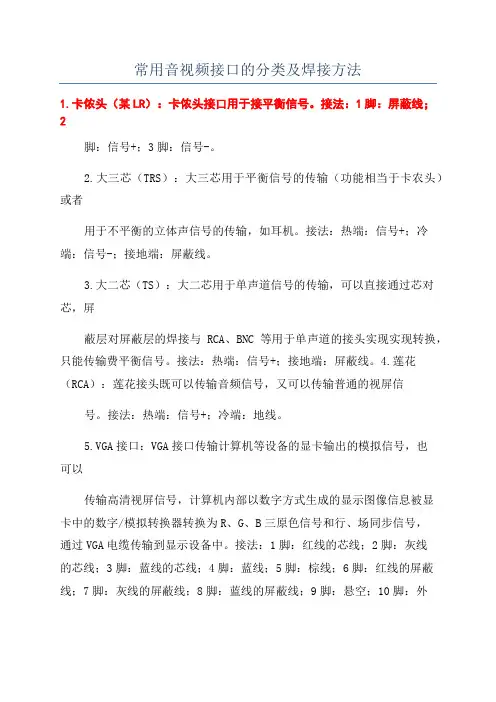
常用音视频接口的分类及焊接方法1.卡侬头(某LR):卡侬头接口用于接平衡信号。
接法:1脚:屏蔽线;2脚:信号+;3脚:信号-。
2.大三芯(TRS):大三芯用于平衡信号的传输(功能相当于卡农头)或者用于不平衡的立体声信号的传输,如耳机。
接法:热端:信号+;冷端:信号-;接地端:屏蔽线。
3.大二芯(TS):大二芯用于单声道信号的传输,可以直接通过芯对芯,屏蔽层对屏蔽层的焊接与RCA、BNC等用于单声道的接头实现实现转换,只能传输费平衡信号。
接法:热端:信号+;接地端:屏蔽线。
4.莲花(RCA):莲花接头既可以传输音频信号,又可以传输普通的视屏信号。
接法:热端:信号+;冷端:地线。
5.VGA接口:VGA接口传输计算机等设备的显卡输出的模拟信号,也可以传输高清视屏信号,计算机内部以数字方式生成的显示图像信息被显卡中的数字/模拟转换器转换为R、G、B三原色信号和行、场同步信号,通过VGA电缆传输到显示设备中。
接法:1脚:红线的芯线;2脚:灰线的芯线;3脚:蓝线的芯线;4脚:蓝线;5脚:棕线;6脚:红线的屏蔽线;7脚:灰线的屏蔽线;8脚:蓝线的屏蔽线;9脚:悬空;10脚:外层屏蔽线;11脚:外层屏蔽线黑线;12脚:绿线;13脚:黄线;14脚:白线;15脚:黑线;金属外壳:外层屏蔽线。
6.BNC接口:主要用于同轴电缆的连接。
7.S端子接口:S端子也是非常常见的端子,其全称是SeparateVideo,也称为SUPERVIDEO。
S-Video连接规格是由日本人开发的一种规格,S指的是“SEPARATE(分离)”,它将亮度和色度分离输出,避免了混合视讯讯号输出时亮度和色度的相互干扰。
S端子实际上是一种五芯接口,由两路视频亮度信号、两路视频色度信号和一路公共屏蔽地线共五条芯线组成。
S端子是日本在AV端子的基础上改进而来的。
从硬件结构来说,S端子实际上是一种五芯接口,由两路视亮度信号、两路视频颜色度信号和一路公共屏蔽地线共五条芯线组成(实际上还有与其配套的亮度、色度分离器)。
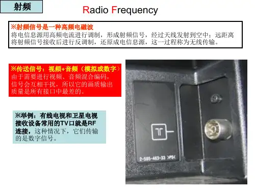
九大视频接口全接触1 射频不像射频接口那样包含了音频信号,复合视频(Composite)通常采用黄***色的RC A(莲花插座)接头。
“复合”含义是同一信道中传输亮度和色度信号的模拟信号,但电视机如果不能很好的分离这两种信号,就会出现虚影。
3 S端子S端子(S-Video)连接采用Y/C(亮度/色度)分离式输出,使用四芯线传送信号,接口为四针接口。
接口中,两针接地,另外两针分别传输亮度和色度信号。
因为分别传送亮度和色度信号,S端子效果要好于复合视频。
不过S端子的抗干扰能力较弱,所以S端子线的长度最好不要超过7米。
4 色差色差(Component)通常标记为Y/Pb/Pr,用红、绿、蓝三种颜色来标注每条线缆和接口。
绿色线缆(Y),传输亮度信号。
蓝色和红色线缆(Pb和Pr)传输的是颜色差别信号。
色差的效果要好于S端子,因此不少DVD以及高清播放设备上都采用该接口。
如果使用优质的线材和接口,即使采用10米长的线缆,色差线也能传输优秀的画面。
5 VGAVGA(Video Graphics Array)还有一个名称叫D-Sub。
VGA接口共有15针,分成3排,每排5个孔,是显卡上应用最为广泛的接口类型,绝大多数显卡都带有此种接口。
它传输红、绿、蓝模拟信号以及同步信号(水平和垂直信号)。
使用VGA连接设备,线缆长度最好不要超过10米,而且要注意接头是否安装牢固,否则可能引起图像中出现虚影。
6 DVIDVI(Digital Visual Interface)接口与VGA都是电脑中最常用的接口,与VGA不同的是,DVI可以传输数字信号,不用再进过数模转换,所以画面质量非常高。
目前,很多高清电视上也提供了DVI接口。
需要注意的是,DVI接口有多种规范,常见的是DVI-D (Digital)和DVI-I(Intergrated)。
DVI-D只能传输数字信号,大家可以用它来连接显卡和平板电视。
DVI-I则在DVI-D可以和VGA相互转换。
视频接口大全(HDMI、DVI、VGA、RGB、分量、S端子、USB接口) 1.S端子标准S端子标准S端子连接线音频复合视频S端子色差常规连接示意图S端子(S-Video)是应用最普遍的视频接口之一,是一种视频信号专用输出接口。
常见的S端子是一个5芯接口,其中两路传输视频亮度信号,两路传输色度信号,一路为公共屏蔽地线,由于省去了图像信号Y与色度信号C的综合、编码、合成以及电视机机内的输入切换、矩阵解码等步骤,可有效防止亮度、色度信号复合输出的相互串扰,提高图像的清晰度。
一般DVD或VCD、TV、PC都具备S端子输出功能,投影机可通过专用的S端子线与这些设备的相应端子连接进行视频输入。
显卡上配置的9针增强S端子,可转接色差S端子转接线欧洲插转色差、S端子和AV与电脑S端子连接需使用专用线,如VIVO线2.VGA接口DVI接口正在取代VGA,图为DVI转VGA的转接头VGA是Video Graphics Adapter的缩写,信号类型为模拟类型,视频输出端的接口为15针母插座,视频输入连线端的接口为15针公插头。
VGA端子含红(R)、黄(G)、篮(B)三基色信号和行(HS)、场(VS)扫描信号。
VGA端子也叫D-Sub接口。
VGA接口外形象“D”,其具备防呆性以防插反,上面共有15个针孔,分成三排,每排五个。
VGA接口是显卡上输出信号的主流接口,其可与CRT显示器或具备VGA接口的电视机相连,VGA接口本身可以传输VGA、SVGA、XGA等现在所有格式任何分辨率的模拟RGB+HV信号,其输出的信号已可和任何高清接口相貔美。
VGA转DVI线,可用在没有VGA接口的设备上目前VGA接口不仅被广泛应用在了电脑上,投影机、影碟机、TV等视频设备也有很多都标配此接口。
很多投影机上还有BGA输出接口,用于视频的转接输出。
3.分量视频接口3RCA连接线标准的3RCA线头分量视频接口也叫色差输出/输入接口,又叫3RCA。
视频输出端口介绍 (HDMI 、DVI 、VGA 、RGB 、分量、S 端子、USB 接口)1.S 端子标准S 端子音频复合视频S 端子色差常规连接示意图S 端子(S-Video )是应用最普遍的视频接口之一,是一种视频信号专用输出接口。
常见的S 端子是一个5芯接口,其中两路传输视频亮度信号,两路传输色度信号,一路为公共屏蔽地线,由于省去了图像信号Y 与色度信号C 的综合、编码、合成以及电视机机内的输入切换、矩阵解码等步骤,可有效防止亮度、色度信号复合输出的相互串扰,提高图像的清晰度。
一般DVD 或VCD 、TV 、PC 都具备S 端子输出功能,投影机可通过专用的S 端子线与这些设备的相应端子连接进行视频输入。
标准S 端子连接线显卡上配置的9针增强S端子,可转接色差S端子转接线欧洲插转色差、S端子和AV与电脑S端子连接需使用专用线,如VIVO线2.VGA接口DVI接口正在取代VGA,图为DVI转VGA的转接头VGA是Video Graphics Adapter的缩写,信号类型为模拟类型,视频输出端的接口为15针母插座,视频输入连线端的接口为15针公插头。
VGA端子含红(R)、黄(G)、篮(B)三基色信号和行(HS)、场(VS)扫描信号。
VGA端子也叫D-Sub接口。
VGA 接口外形象“D”,其具备防呆性以防插反,上面共有15个针孔,分成三排,每排五个。
VGA接口是显卡上输出信号的主流接口,其可与CRT显示器或具备VGA接口的电视机相连,VGA接口本身可以传输VGA、SVGA、XGA等现在所有格式任何分辨率的模拟RGB+HV信号,其输出的信号已可和任何高清接口相貔美。
VGA转DVI线,可用在没有VGA接口的设备上目前VGA接口不仅被广泛应用在了电脑上,投影机、影碟机、TV等视频设备也有很多都标配此接口。
很多投影机上还有BGA输出接口,用于视频的转接输出。
3.分量视频接口3RCA连接线标准的3RCA线头分量视频接口也叫色差输出/输入接口,又叫3RCA。
视频监控设备常见25种接口,技术人员必备的监控知识
视频监控设备有各种接口,通过接口来连接不同的设备,使实不同的功能。
常见的有视频接口、音频接口、网络接口,HDMI接口、VGA接口,RS485接口等,因设备功能的不同,设备接口或多或少,或不同或相同。
比如NVR设备有网口、HDMI和VGA的视频输出接口用于接显示器,而没有NBC的视频接口,因为NVR是网络硬盘录像机,只接收IP数字视频流。
而DVR设备是硬盘录像机,接模拟信号的,需要有BNC接头,同时也需要联网和视频输出,所以同样有网口,HDMI和VGA视频信号输出接口。
视频监控系统中的监控摄像机、DVR、NVR等设备常见的接口整理了一下,不少于25种,每种的功能用途以图片的形式进行说明,视频监控各种设备接口如下。
今天,对于一些小型视频监控系统,有些接口已经消失,常用的有网口、USB口、HDMI接口等。
但规范较大的视频监控系统,系统设备种类繁多,各种接口依然存在。
以上这些视频监控接口及功能,
安防技术人员不可不知,一定要记牢。
视频接口大全(HDMI、DVI、VGA、RGB、分量、S端子、USB接口) 1.S端子标准S端子标准S端子连接线音频复合视频S端子色差常规连接示意图S端子(S-Video)是应用最普遍的视频接口之一,是一种视频信号专用输出接口。
常见的S端子是一个5芯接口,其中两路传输视频亮度信号,两路传输色度信号,一路为公共屏蔽地线,由于省去了图像信号Y与色度信号C的综合、编码、合成以及电视机机内的输入切换、矩阵解码等步骤,可有效防止亮度、色度信号复合输出的相互串扰,提高图像的清晰度。
一般DVD或VCD、TV、PC都具备S端子输出功能,投影机可通过专用的S端子线与这些设备的相应端子连接进行视频输入。
显卡上配置的9针增强S端子,可转接色差S端子转接线欧洲插转色差、S端子和AV与电脑S端子连接需使用专用线,如VIVO线2.VGA接口DVI接口正在取代VGA,图为DVI转VGA的转接头VGA是Video Graphics Adapter的缩写,信号类型为模拟类型,视频输出端的接口为15针母插座,视频输入连线端的接口为15针公插头。
VGA端子含红(R)、黄(G)、篮(B)三基色信号和行(HS)、场(VS)扫描信号。
VGA 端子也叫D-Sub接口。
VGA接口外形象“D”,其具备防呆性以防插反,上面共有15个针孔,分成三排,每排五个。
VGA接口是显卡上输出信号的主流接口,其可与CRT显示器或具备VGA接口的电视机相连,VGA接口本身可以传输VGA、SVGA、XGA等现在所有格式任何分辨率的模拟RGB+HV信号,其输出的信号已可和任何高清接口相貔美。
VGA转DVI线,可用在没有VGA接口的设备上目前VGA接口不仅被广泛应用在了电脑上,投影机、影碟机、TV等视频设备也有很多都标配此接口。
很多投影机上还有BGA输出接口,用于视频的转接输出。
3.分量视频接口3RCA连接线标准的3RCA线头分量视频接口也叫色差输出/输入接口,又叫3RCA。
视频各种接口详细图解面对众多的接很多初级用户在看投影机文章或将投影机与其它设备进行连接时,转接方法,在使用时您会觉口总是感到茫然。
其实只要弄明白它们的用途和连/得其也并非有登天之难。
投影机接口虽没有高档功放上那么多但也不少38/ 1家用投影机上的常用接口拉近点就看清楚一、常规视频输入端子的数量远多于输出端子,=投影机上输入端子做为视频播放设备,(端子接口)视频端子的数量也远多于音频端子。
)标准视频输入(●RCA38/ 2RCA是莲花插座的英文简称,RCA输入输出是最常见的音视频输入和输出接口,也被称AV接口(复合视频接口),通常都是成对的,把视频和音频信号“分开发送”,避免了因为音/视频混合干扰而导致的图像质量下降。
但由于AV 接口传输的仍是一种亮度/色度(Y/C)混合的视频信号,仍需显示设备对其进行亮/色分离和色度解码才能成像,这种先混合再分离的过程必然会造成色彩信号的损失,所以其目前主要被用在入门级音视频设备和应用上。
音频转RCA线38/ 3RC转接延长头插入示意图AV 白色的是音频接口和黄色的视频接口,使用时只需要将带莲花头的标准线缆与其它输出设备(如放像机、影碟机)上的相应接口连接起来即可。
38/ 4不要小瞧RC,其也有做工不错的高档端S端子S标准38 / 5端子连接标S38/ 6音频复合视频端子色差常规连接示意图S是一种视频信号专用输出是应用最普遍的视频接口之一,S端子(S-Video)芯接口,其中两路传输视频亮度信号,两路传输接口。
常见的S端子是一个5的综合、一路为公共屏蔽地线,由于省去了图像信号与色度信号YC色度信号,编码、合成以及电视机机内的输入切换、矩阵解码等步骤,可有效防止亮度、色度信号复合输出的相互串扰,提高图像的清晰度。
端子输出功能,投影机可通过专用的都具备S、或一般DVDVCD、TVPC 端子线与这些设备的相应端子连接进行视频输入。
SS端子,可转接色差针增强显卡上配置的938/ 7端子转接线38/ 8AV欧洲插转色差、S端子和S与电脑端子连接需使用专用线,如VIVO线芯(不带4接口,包含端子在一些投影机厂家的称呼只中又被称为Smini-DIN 个声道的讯号输出)等不8765音效输出)、芯、芯、芯、芯、69芯(能提供同的产品都在投影机上被使用。
各种视频插头插座接口介绍视频插头插座接口是用于连接视频设备和显示设备之间的接口,方便信号传输和显示设备的连接。
不同的视频接口有不同的特点和用途,下面将介绍一些常见的视频插头插座接口。
1. VGA接口(Video Graphics Array)VGA接口是一种模拟信号接口,被广泛应用于计算机显示设备。
它使用15个金属接点进行数据传输,通过RGB信号传输图像数据,使用另外两个信号线传输水平和垂直同步信号。
VGA接口已逐渐被数字接口所取代,但在一些老旧的设备上仍然可以见到。
2. DVI接口(Digital Visual Interface)DVI接口是一种数字信号接口,可以传输高质量的数字视频信号。
它支持模拟和数字信号传输两种模式,通过不同的连接线可以实现单链、双链和高清电视等不同版本的DVI接口。
DVI接口可以连接计算机和显示器等设备,但是它已逐渐被HDMI和DisplayPort所取代。
HDMI接口是一种支持高清视频和多声道音频传输的数字接口,可以连接电视、投影仪、电脑和音频设备等。
HDMI接口传输质量高、方便易用,并且支持多种分辨率和音频格式。
现在的很多电视和电脑显示器都配备了HDMI接口。
4. DisplayPort接口DisplayPort接口是一种数字接口,用于连接显示器和视听设备。
它支持高分辨率和高刷新率的视频传输,具有较高的数据传输速度和性能。
DisplayPort接口还可传输音频信号,并且可以通过适配器与HDMI、DVI 和VGA等其他接口兼容。
5. Thunderbolt接口Thunderbolt接口是一种高速数据传输和显示接口,由Intel开发。
它支持高分辨率视频传输、高速数据传输和电源供应等功能,具有极高的性能和灵活性。
Thunderbolt接口和DisplayPort接口可以互相兼容,因此可以通过适配器连接到其他视频接口。
6. RCA接口(Radio Corporation of America)RCA接口是一种模拟信号接口,常用于电视、摄像机和音频设备等。
各种视频插头插座接口介绍(引脚定义)SCART plug & connector: CENELEC (Comité Européen de Normalisation Electrotechnique) EN 50 049-1 / IEC 933-1Pin No. Signal Inter Conne-ction Pin No.1 Audio right channel output (0.5 Vrms, < 1K ohms) 22 Audio right channel input (0.5 Vrms, > 10K ohms) 13 Audio left channel output (0.5 Vrms, < 1K ohms) 64 Audio ground 45 Blue signal ground 56 Audio left channel input (0.5 Vrms, > 10K ohms) 37 Blue signal I/O (0.7 Vp-p, 75 ohms) 78 Function switching I/O (L: < 2V, H: > 10V, 10K ohms) 89 Green signal ground 910 Intercommunication data line No. 1 1011 Green signal I/O (0.7 Vp-p, 75 ohms) 1112 Intercommunication data line No. 2 1213 Red signal ground 1314 Blanking signal ground 1415 Red signal I/O (0.7 Vp-p, 75 ohms) 1516 Blanking signal I/O (L: < 0.4V, H: >1.0V, 75 ohms) 1617 Composite video signal ground 1818 Blanking signal ground 1719 Composite video signal output (1 Vp-p, 75 ohms, sync: negative) 2020 Composite video signal input (1 Vp-p, 75 ohms, sync: negative) 1921 Plug shield (common ground) 21screen.width-500)this.style.width=screen.width-500;" border=0>此主题相关图片如下:screen.width-500)this.style.width=screen.width-500;" border=0>EIAJ RGB plug & connector: EIAJ TTC-003Outlook of plug and connector including pin assignment are the same as SCART plug and connectorPin No. Signal Inter Conne-ction Pin No.1 Audio left channel input (0.40 mVrms, > 47K ohms) 12 Audio left channel output (0.40 mVrms, > 10K ohms) 23 Audio ground 34 Audio ground 45 Audio right channel input (0.40 mVrms, > 47K ohms) 66 Audio right channel output (0.40 mVrms, > 10K ohms) 57 Video ground 78 Video ground 89 CVBS input (1 Vp-p, 75 ohms, sync: negative) 1010 CVBS output (1 Vp-p, 75 ohms, sync: negative) 911 AV control input 1112 Ym input (switch for R, G & B signal to half tone level, L: < 0.4, H: > 1.0, 75 ohms) 1213 Red signal ground 1314 Ground 1415 Red signal I/O (0.7 Vp-p, 75 ohms) 1516 Ys input (switch for R, G & B signal from/to internal and external,L: < 0.4, H: > 1.0, 75 ohms) 1617 Green signal ground 1718 Blue signal ground 1819 Green signal I/O (0.7 Vp-p, 75 ohms) 1920 Blue signal I/O (0.7 Vp-p, 75 ohms) 2021 Plug shield 21S-connector: EIAJ CP-1211, IEC 84(s)80Pin No. Signal1 Luminance (Y) signal ground2 Chrominance (C) signal ground3 Luminance (Y) signal I/O (1 Vp-p, 75 ohms, sync: negative)4 Chrominance (C) signal I/O (burst: 0.286 Vp-p, 75 ohms)S1 and S2 connectorPin No. S1 connector S2 connector1 Luminance (Y) signal ground Luminance (Y) signal ground2 Chrominance (C) signal ground Chrominance (C) signal ground3 Luminance (Y) signal I/O (1 Vp-p, 75 ohms, sync: negative) Luminance (Y) signal I/O (1 Vp-p, 75 ohms, sync: negative)4 Chrominance (C) signal I/O (burst: 0.286 Vp-p, 75 ohms)Squeeze control input:+ 5V DC / >100KW Chrominance (C) signal I/O (burst: 0.286 Vp-p, 75 ohms)Squeeze control input:+ 5V DC / >100KWLetterbox control input:+ 2.2V DC / >100KWscreen.width-500)this.style.width=screen.width-500;" border=0>screen.width-500)this.style.width=screen.width-500;" border=0>EIAJ D-connector D1/2/3/4/5: EIAJ RC-5237Pin No. Signal1 Y signal I/O (+700 mV & sync: +/-300 mV *1, 75 ohms)2 Y_GND3 PB (+/- 350 mV, 75 ohms)4 PB_GND5 PR (+/- 350 mV, 75 ohms)6 PR_GND7 Reserved line 18 Line 1 (0V: 525 lines, 2.2V: 750 lines, 5V: 1125 lines)9 Line 2 (0V: 59.94i / 60i, 2.2V: -, 5V: 59.94p / 60p)10 Reserved line 211 Line 3 (0V: 4:3, 2.2V: 4:3 letter box, 5V: 16:9)12 Plug insert detect GND13 Reserved line 314 Plug insert detect (output: 10K ohms, input: >100K ohms)hooks Shell GND*1: for 1125i and 750p. -300mV for 525p/525i, superimposed in Y signalNote: Indication for video signal format (i: interlace, p: progressive) D1: 525iD2: 525i, 525pD3: 525i, 525p, 1125iD4: 525i, 525p, 1125i, 750pD5: 525i, 525p, 1125i, 750p, 1125pscreen.width-500)this.style.width=screen.width-500;" border=0>VESA DFP connector: VESA (Video Electronics Standards Association) Digital Flat Panel (DFP) StandardPin No. Signal Name Signal1 TX1+ TMDS positive differential output, channel 12 TX1- TMDS negative differential output, channel 13 SHLD1 Shield for TMDS channel 14 SHLDC Shield for TMDS clock5 TXC+ TMDS positive differential output, reference clock6 TXC- TMDS negative differential output, reference clock7 GND Logic Ground8 +5V Logic +5V DC Supply from the Host9 No Connect No Connection10 No Connect No Connection11 TX2+ TMDS positive differential output, channel 212 TX2- TMDS negative differential output, channel 213 SHLD2 Shield for TMDS channel 214 SHLD0 Shield for TMDS channel 015 TX0+ TMDS positive differential output, channel 016 TX0- TMDS negative differential output, channel 017 No Connect No Connection18 HPD Hot Plug Detection (+5V DC to Host)19 DDC_DAT DDC2B Data20 DDC_CLK DDC2B ClockTMDSTM: Transition Minimized Differential SignalingDDC: Display Data ChannelDDC2B: Simplest of the DDC modes defined in the VESA DDC standardscreen.width-500)this.style.width=screen.width-500;" border=0>此主题相关图片如下:screen.width-500)this.style.width=screen.width-500;" border=0>VESA P&D connector: Plug and Display Standard (P&DTM)Pin No. SignalPin No. Signal1 TMDS Data2 + 16 USB data +2 TMDS Data2 - 17 USB data -3 TMDS Data return 18 1394 outer sahield (optional) & Charge Power return4 Unused 19 1394 Vg5 Unused 20 1394 Vp6 Unused 21 TMDS Data0 +7 TMDS Clock return 22 TMDS Data0 -8 Charge power + 23 TMDS Data return9 1394 pair A, data - 24 Unused10 1394 pair A, data + 25 DDC return11 TMDS Data1 + 26 DDC data (SDA)12 TMDS Data1 - 27 DDC clock (SCL)13 TMDS Data return 28 +5V DC14 TMDS Clock + 29 1394 pair B, clock +15 TMDS Clock - 30 1394 pair B, clock -(TMDS: Trademark of Silicon Image, USB: universal serial bus, DDC: display data channel, SDA: serial data, SCL: serial clock)screen.width-500)this.style.width=screen.width-500;" border=0>此主题相关图片如下:screen.width-500)this.style.width=screen.width-500;" border=0>IEEE 1394-1995:Pin No. Signal Name Signal Inter ConnectionInter Connection with i-Link1 VP Cable power 12 VG Cable ground 23 TPB* Strobe on receive, data on transmit (differential pair) 5 14 TPB 6 25 TPA* Strobe on receive, data on transmit (differential pair) 3 36 TPA 4 4screen.width-500)this.style.width=screen.width-500;"border=0>screen.width-500)this.style.width=screen.width-500;" border=0>i-Link: 4-pin type IEEE 1394-1995Pin No. Signal Name Signal Inter ConnectionInter Connection with 1394-19951 TPB* Strobe on receive, data on transmit (differential pair) 3 52 TPB 4 63 TPA* Strobe on receive, data on transmit (differential pair) 1 34 TPA 2 4screen.width-500)this.style.width=screen.width-500;" border=0>此主题相关图片如下:screen.width-500)this.style.width=screen.width-500;" border=0>VGA (15-pin Dsub connector: for analog interface of PC monitorPin No. SignalPin No. Signal1 Red video input 9 No pin2 Green video input 10 Digital ground3 Blue video input 11* Monitor ID 0 / Ground4 Monitor ID 2 / Ground 12* Monitor ID 1 / Serial data line (SDA) 5* Digital ground / Self test 13 Horizontal sync / H+V6 Red video ground 14 Vertical sync (VCLK for DDC)7 Green video ground 15* Reserved / Data clock line (DCL)8 Blue video groundscreen.width-500)this.style.width=screen.width-500;"border=0>screen.width-500)this.style.width=screen.width-500;" border=0。