丹佛斯变频器怎么选型、丹佛斯选型指南
- 格式:docx
- 大小:241.32 KB
- 文档页数:9

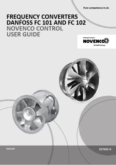
Pure competence in air.927665-0FREQUENCY CONVERTERS DANFOSS FC 101 AND FC 102NOVENCO CONTROL USER GUIDE927665-0GBFrequency converters Danfoss FC 101 and FC 102Novenco control user guideContents1.General2.Wire configuration3.First time run after installation4.Configuration of FC101 converter5.Configuration of FC102 converter6.Modbus configuration7.Reference documentation8.Patents and trademarks9.Declaration of conformity1.GeneralThe procedures in this guide serve as examples of how to control the Danfoss FC 101 and FC 102 frequency con-verters in combination with Novenco fans.Please read all relevant parts of this complete guide.Procedures and methods in this guide should be fol-lowed for the warranty to remain valid.2.Wire configurationCheck wires are correctly connected•Check that a wire connects the terminals no. 12 and 27 in the frequency converter.•Connect a control wire to terminal no. 18 in the fre-quency converter. The terminal must pull high (24V) to activate the converter.•Check the signal wire is connected to terminal no. 53. For voltage control the signal levels are 0 - 10V and for current control the levels are 4 - 20mA.•Check that ground is connected to terminals no. 20 and 55.Table 1.Icons in guideFigure 2Terminal block set up for current control3.First time run after installationHow to check the installation is correct1.Check the installation is powered off on the mainswitch.2.Check the fan and frequency converter are in-stalled correctly. Refer to the installation and maintenance guides for the fan and frequency converter.3.Power on the installation at the main switch. Thefrequency converter starts in idle mode.4.Push Hand On on the local control panel (LCP)on the frequency converter. This activates the fan rotor.5.Check the direction of rotation is consistent withthe arrows on the fan casing.6.Turn off the installation at the main switch.7.Connect the start signal wire to terminal no. 18.8.Voltage or current mode:Connect the reference wire to terminal no. 53.Modbus mode:Connect the reference wires to terminals no. 68 and 69.4.Configuration of FC101 converterThe converter is set up for voltage mode as standard. The minimum speed is indicated with 0V and the max-imum speed with 10V.Figure 3Wire diagram for the FC101+10 V DC4.1Change from voltage to current con-trolHow to change the FC101 to current control1.Push the Menu button on the LCP on the fre-quency converter.2.Push the ↓ and ↑ buttons to navigate to the Wiz-ard. Push OK to select.3.Push ↓ to navigate to the following menu item.6-19 Terminal 53 mode[1] Voltage mode4.Push OK to access and use the ↓ and ↑ to selectcurrent mode.5.Push OK to accept.The frequency converter now operates in current mode for control signals. The minimum speed is indicated with 4mA and the maximum speed with 20mA.5.Configuration of FC102 converter The converter is set up for voltage mode as standard.The minimum speed is indicated with 0V and the max-imum speed with 10V.Figure 4Wire diagram for the FC1025.1Change from voltage to current con-trolHow to change the FC102 to current control1.Remove the screw that holds the lid on the fre-quency converter.2.Pull out the LCP with a straight pull.3.Locate the text A53 U - I.4.Push the button from position U to I with ascrewdriver.5.Put the LCP back.6.Attach the lid and insert the screw.The frequency converter now operates in current mode for control signals. The minimum speed is indicated with 4mA and the maximum speed with 20mA. 6.Modbus configurationAll parameters are accessible through Modbus RTU (Re-mote Terminal Unit) either directly or via PCD (Process Data).To setup the Modbus RTU1.Push the Menu button two times.2.Push ↓ to navigate to8-** Comm. and Options.3.Push OK.4.Push ↓ to navigate to 8-3 FC port settings.5.Push OK.6.Push OK again.7.Push ↓ to navigate to [2] Modbus RTU.8.Push OK to confirm.9.Push ↓ to navigate down and check the followingsettings.•Address•Baud Rate•Parity / Stop bit•Minimum Response Delay•Maximum Inter-char..10.Push OK to select, the ↓ and ↑ buttons to changeand push OK to confirm settings.Write and start-stop notes•PCD: It is possible to configure up to 64 parame-ters in PCDs.Write PCDs in par. 8-42.xx, and read PCDs in par.8-43.xx. These PCDs are accessible via holdingregisters 28xx and 29xx.•Write control word: Par. 8-42.0 and par. 8-42.1 areset to the control word and as reference, respec-tively. Set par. 8-42[2-63] to the par. no. to write to.•Start-stop: Write the control word to register 2810to start or stop the converter.Read notes•The reference register is 2811 with 0 - 4000hex(0-100%).•Read status word: Par. 8-43.0 and par. 8-43.1 areset to status word and main actual value, respec-tively. Set par. 8-43[2-63] to the par. no. to readfrom.Figure 5Location of terminal 53Bit Bit value = 0Bit value = 100Reference value External selection LSB01Reference value External selection MSB02DC brake Ramp03Coasting No coasting04Quick stop Ramp05Hold output frequency Use ramp06Ramp stop Start07No function Rest08No function Jog09Ramp 1Ramp 210Data invalid Data valid11Relay 01 open Relay 01 active12Relay 02 open Relay 02 active13Parameter set-up Selection LSB14< Not used >< Not used >15No function ReverseTable 2.Control word bit positions•Read status word: Read the status word from reg-ister 2910.Other notes•Set the speed, i.e. the main actual value, with reg-ister 2911.•Read the configuration of par. 8-43.3.. with regis-ter 2912.•To configure a PCD to read a 32bit parameter re-quires configuration of two consecutive PCDs to the same parameter. For example, the parameter 16-10 Power [kW] is a 32bit integer, which may be configured in par. 8-43.2 and 8-43-3, or par. 8-43.4 and 8-43.5 and so on.The sizes of the different parameters are available in the programming guide.•To address parameters directly use the register no. = parameter no. x 10. For example, the par. 16-90 is accessible via register no 16900.•Some PLCs have 0 offsets, which means the value 1 must be subtracted from the register no. For ex-ample, reg. 2810 is 2809 etc.00Control not ready Control ready 01Drive not ready Drive ready 02Coasting Enable 03No error Trip04No error Error (no trip)05Reserved -06No error Triplock 07No warningWarning08Speed reference Speed = reference 09Local operationBus control10Out of frequency limit Frequency limit ok 11No operation On operation12Drive ok Stopped, auto start 13Voltage ok Voltage exceeded 14Torque ok Torque exceeded 15Timer okTimer exceededTable 3.Status word bit positionsNovenco Building & Industry A/S Industrivej 22Tel. +45 70 77 88 994700 Naestved Denmark7.Reference documentation•Danfoss Operating guideVLT ® HVAC basic drive FC 101Publication no. MG18AA02, 04/2018•Danfoss Programming guide VLT ® HVAC basic drive FC 101Publication no. MG18B502, 04/2018•Danfoss Design guideVLT ® HVAC basic drive FC 101Publication no. MG18C802, 04/2018•Danfoss Operating guide VLT ® HVAC drive FC 102Publication no. MG16O202, 04/2018•Danfoss Programming guide VLT ® HVAC drive FC 102Publication no. MG11CE02, 03/2015•Danfoss Design guide VLT ® HVAC drive FC 102Publication no. MG11BC02, 06/20148.Patents and trademarksNovenco ®ZerAx ® is a registered trademark of Novenco Building & Industry A/S.AirBox™ and NovAx™ are trademarks of Novenco Building & Industry A/S.VLT ® is a registered trademark of Danfoss A/S.The ZerAx ® processes of manufacture, technologies and designs are patented by Novenco A/S or Novenco Building & Industry A/S.Pending patents include Brazil no. BR-11-2012-008607-3, BR-11-2012-008543-3, BR-11-2012-008545-0, BR-11-2014-002282-8 and BR-11-2014-002426-0; India no. 4140/CHENP/2012, 4077/CHENP/2012, 821/CHENP/2014 and 825/CHENP/2014; PCT no. EP2012/064908 and EP2012/064928; South Korea no. 10-2012-7012154.Granted patents include Canada no. 2.777.140,2.777.141, 2.777.144, 2.832.131 and 2.843.132; China no. ZL2010800458842, ZL2010800460965, ZL2010800464275 and ZL2012800387210; EU no. 2488759, 2488760,2488761, 2739860 and 2739861; India no. 312464; South Korea no. 10-1907239, 10-1933724, 10-1980600 and 10-2011515; US no. 8.967.983, 9.200.641, 9.273.696 B2,9.683.577 and 9.926.943 B2. Granted designs include Bra-zil no. BR-30-2012-003932-0; Canada no. 146333; China no. 1514732, 1517779, 1515003, 1555664 and 2312963; EU no. 001622945-0001 to 001622945-0009 and 001985391 - 0001; India no. 246293; South Korea no. 30-0735804; US no. D665895S, D683840S, D692119S, D704323S,D712023S, D743018S, D755363S, D756500S, D821560S and D823452S.The NovAx Basic jet fans manufacturing processes, technologies and designs are patented by Novenco A/S or Novenco Building & Industry A/S.Granted patents include EU no. 2387670 and United Arab Emirates no. 1372. Granted designs include EU no. 001069884-0003, 001069884-0008, 001069884-0010, 001069884-0013, 001069884-0017, 001069884-0019, 001069884-0022, 001069884-0026 and 001069884-0028; United Arab Emirates no. D223/2009.The CGF jet fans designs are patented by Novenco A/S or Novenco Building & Industry A/S.Granted designs include EU no. 001610643-0001 to 001610643-0005.Copyright © 2016 - 2020,Novenco Building & Industry A/S.All rights are reserved.9.Declaration of conformityRefer to the declaration information in the documenta-tion for the fans and frequency converters.Figure 6QR code to this guide onPure competence in air. ttt͘EKs E Kͳ h/> /E'͘ KD。


目录1. 如何阅读本设计指南3版权声明、责任限制和修订权利3认证3符号4缩略语4定义52. VLT AQUA 变频器简介11处理说明12CE 标志12空气湿度14腐蚀性环境14振动15VLT AQUA 控制18PID20关于 EMC 的一般问题28高低压绝缘 (PELV)31接地泄漏电流31用制动功能控制32机械制动控制33极端运行条件33安全停止操作353. VLT AQUA 选择37一般规范37主电源 3 x 200 - 240 VAC37主电源 3 x 380 - 480 VAC41效率49特殊条件53降容的目的53通过自动调整确保性能55机械尺寸56选件和附件57模拟输入输出选件 MCB 109624. 如何订购67订购单67类型代码字符串68订购号695. 如何安装73机械安装73附件包73电气安装75拆除外接电缆的挡板75访问控制端子82电气安装,控制端子83最终设置和测试85最终设置和测试85安全停止安装87安全停止试运行88附加连接88其他连接安装92安全性95符合 EMC 规法的安装95漏电断路器996. 应用示例1017. RS-485 安装和设置109RS-485 安装和设置109 FC 协议概述111网络配置112 FC 协议消息帧结构112示例117 Modbus RTU 概述118带有 Modbus RTU 的 VLT AQUA118 Modbus RTU 消息帧结构119如何访问参数123示例123 Danfoss FC 控制协议1288. 疑难解答135索引1411.1.1.1.版权声明、责任限制和修订权利本出版物含有 Danfoss A/S 专有的信息。
用户接受和使用本手册,即表示用户同意仅将本文所含信息用于操作 Danfoss A/S 设备,或者用于操作其它供应商提供的用于通过串行通讯线路同 Danfoss 设备通讯的设备。
本出版物受丹麦和其它大多数国家/地区的版权法保护。
丹佛斯变频器怎么选型、丹佛斯选型指南丹佛斯变频器选型指南一、引言变频器作为工业自动化系统中的重要设备,广泛应用于各个行业。
丹佛斯作为一家全球知名的工业自动化解决方案供应商,其丰富的产品线和技术经验使其成为变频器市场的领导者之一。
本文将介绍丹佛斯变频器的选型方法和注意事项,帮助用户更好地选择合适的变频器。
二、丹佛斯变频器产品线介绍丹佛斯的变频器产品线包括低压和中压两个系列,每个系列又包括多个型号和规格。
用户在选型时需要根据具体应用场景和需求选择合适的产品。
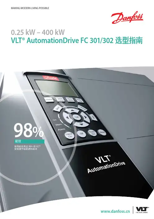
2.1 低压系列丹佛斯低压系列变频器适用于功率范围较小的应用,常见型号有VLT Micro Drive、VLT AutomationDrive FC 301和VLT AutomationDrive FC 302.用户在选择时可以根据需要考虑功率、电压等因素。
2.2 中压系列丹佛斯中压系列变频器适用于功率较大的应用,常见型号有VLT Midi Drive和VLT AQUA Drive等。
用户在选择时需要确定需求的功率范围以及其他特定要求。
三、丹佛斯变频器选型步骤在选型过程中,用户需要根据具体需求和应用场景进行综合考虑。
以下是一个简单的选型步骤,供参考:3.1 确定应用要求首先,用户需要明确应用的要求,包括需求的功率范围、电压等。
同时还需要考虑特殊的环境因素,如温度、湿度、尘埃等。
3.2 确定负载类型根据应用的负载类型,用户可以选择相应的变频器型号。
丹佛斯的变频器适用于多种负载类型,包括泵、风机、压缩机等。
3.3 确定控制方式用户需要确定变频器的控制方式,包括开环控制和闭环控制。
开环控制适用于简单的应用,闭环控制适用于对控制精度有要求的应用。
3.4 确定通信接口根据系统的要求和需要,用户需要确定变频器是否需要支持通信接口,如Modbus、Profibus、Ethernet等。
3.5 考虑其他特殊要求根据具体应用的要求,用户还需要考虑其他特殊要求,如故障保护、过载保护、防护等级等。
丹佛斯变频器怎么选型、丹佛斯选型指南丹佛斯变频器选型指南
1:产品概述
1.1 丹佛斯变频器的定义
1.2 变频器的作用和应用领域
2:选型前准备
2.1 确定负载类型和特点
2.2 确定所需的工作频率范围
2.3 确定负载的额定功率和电压
2.4 考虑安装环境和工作温度要求
3:选择变频器的关键因素
3.1 负载特性对变频器的要求
3.2 工作频率范围对变频器的要求
3.3 功率和电压要求对变频器的要求
3.4 变频器的性能指标和功能要求
4:选择合适的丹佛斯变频器系列
4.1 丹佛斯变频器产品系列介绍
4.2 各系列产品的特点和适用范围
4.3 根据选型需求选择合适的系列
5:进一步筛选选型
5.1 根据负载的功率和电压要求筛选产品 5.2 根据工作频率范围筛选产品
5.3 根据负载特性要求筛选产品
5.4 根据性能指标和功能要求筛选产品6:安装及调试
6.1 变频器的安装注意事项
6.2 变频器的参数设置
6.3 变频器的调试方法和步骤
附件:
1:变频器选型表格
2:丹佛斯变频器型录
法律名词及注释:
1:变频器:全称为变频调速器,是一种将电源交流频率变换,从而实现电机转速调节的装置。
2:负载:指电机、设备或系统等所承受的力、功率或扭矩。
3:工作频率范围:变频器能够调节电机输出频率的范围。
4:功率:指电机或设备的额定功率,表示其所能提供的最大
输出功率。
5:电压:指电机或设备的额定电压,表示其能够承受的最大
电压。
丹佛斯FC302变频器选型总结变频器如何选型是我们技术人员和商务报价人员经常遇到的问题。
下面根据工作实际经验给大家总结的一些方法和思路。
首先要考虑的因素包括:品牌,功率,电流,电压,负载(就是电机拖动的设备),应用场合另外还有一些选配件要在选择的时候注意比如控制面板是否单独采购,需要不需要用滤波器,电抗器,制动电阻制动单元等。
一些专业设备要选择专用变频器。
比如注塑机,电梯,纺织一些场合选择专用变频器更好用。
变频器常用功率0. 75KW, 1.5 K肌2.2 K肌3.7 K肌5.5 K肌7.5 K肌11 K肌15 KW, 18. 5 K肌22 K肌37 K肌45 K肌55 K肌75 K肌90 K肌110 K肌132 KW, 160 K肌185 K肌200 K肌220 K肌250 K肌285 K肌312 K肌355 KW 一般变频器型号都是按功率大小进行定义型号的,值得注意的是进口品牌的控制面板都需要单独采购,变频器价格不含控制面板,而国产变频器一般都包含控制面板。
一般来说电机的功率是变频器选择变频器功率的基础。
但是值得注意的是变频器时应以实际电机电流值作为变频器选择的依据,电机的额定功率只能作为参考。
风机水泵应用场合负载较小,一般变频器厂家都有专门的系列变频器。
而一些特殊场合负载大一般都要适当的放大档使用。
1、丹佛斯选型手册截图:自由组合的硬件1 2 3 4 5 6 7 8 9 10 11 12 13 14 15 16 17 %)9 20 21PK260.26WV P56K BSkWPK370J7kW P76K75kWPK560.66kW P90K90kWPK75O.TOkW PUO11CkWP1K1 1.1kW P132132kWP1K5i.5kW pieo IflOkWP2K22-iiW P20Q2CXMW P3K03kW P26028(*WP3K73,7kW P315316MVP4K04fcW P3653SB*W P5K6 5.5kW P400400kWP7K673kW P46045CkW P11K1HW P5O0500kWP15K15kW P56Q MOkWP18K tSSkW P630830kWP22K22kW P7107lCfcW P30K30kW paw aookwP37K37kW P90Q9O0kW P46K46kW PtMO1O0OWV Eoo/coaIPOO»SW 刊酗网即阳13JPOO 62O/P2O IP2WltM5»ft®89P20E21/P21E54IP2傍融带安笠刎fe的P2iIPSl*®E56/P561%5号吸存如融唬的PSbEBBE2Mipeeai®|阳号&带:必保EE5M用工寿WEF,程可埠2:L2X IP21WR 除:朝3~^»1红L5X矽®出H211阳号乱畸嚏处案,关H54碇帮献1阿关R2X IP2偈应用Q 一的鼠崎关「柜tJKSxnr »«,±R8X阳6银,窄Q 妁蠢.话或)关「•柜灯敏30\不森・出•注寰军苑£1袅C»奂负眠於用曲期P11K0二百松四0转限,下(殳贡题.70用51大T #«? : ««1汨MS除⑺坦虐若尊侵孑划C4法件- -仅80V -Hi 立频千的8两.C1®表来的巡M2 那频干扰递麴•C3ffi MIL W御漫HA 射顿干优湿施.C2® 奈来的A1GHB•&用电地干扰a»«8g __________________22 23 24 25 26 27 28 29 30 31 32 33 34 35 36 37 38 39X S XA疆D万比r电&酗您*共享都子 黄敦尹不竭子 土沿关 士:治关但超王M 克容FISK 出联/,时于 era士;田美和公―里子 士二寿关、箍器由J1更 士层性指石..,触第婕・等 士‘田关、;•咕维、 子回❸断器土丁岩新诳空、吃案氏9 主布卧凿壁和解断骂MCO3g350/351 卷 句、州步2、选型原则:±_落就逐四..长0三孽暹子杓18壁落D3-34I 运期91RC CX|3647>流动演歌件»(~尤..iD 彩4t0 MC0950代步;制雌H MCO»1 SS12MCO352 工EM :,科杵豆范君匚,■'0X 无的DO_ MC8I07 24VAMc 入Sggi3srw^^«MCB113T •,至迄24 27登独"内・*叔门 SXXX 标睢也1 >选型中带有prof inet网卡和24V供电,型号为FC302PK55T5E20H1GCALD0,其中最后四位AL 表示profinet 网卡,DO 表示24V 外接电源。
丹佛斯变频器经验分享(一)以下丹佛斯变频器在销售、技术服务过程中碰到的一些问题,写出来跟大家共同分享,同时也希望公司所有人员若在工作过程中有遇到问题,有新的经验(无论是技术或商务)也可以提出来大家共同分享,共同学习,共同进步。
(信息可提交至商务部)FC300 系列变频器经验分享1. FC300 系列变频器模拟量输出只有一路,比VLT5000 系列少一路。
若客户有需要2路模拟量输出,FC300系列产品可增加选件(通用I/O MCB-101,置公司面价:856 ,外置面价:1712 )。
2. 适配器Sub-D9 接口不能用于FC302-110kw(美国产)以上产品FC300 系列产品,有一个Profibus 适配器,用途是将Profibus 选件标配的5 线接头转换成9 芯接头,FC300-90kw 以下产品,使用此转换器非常合适,不存在安装问题。
但大于110kw 产品,由于设计的安装空间小于130B1112适配器实际尺寸。
所以,此选件不适应FC300-110kw 以上产品。
目前解决办法:自制转换接头。
3. FC300 负滑差补偿实现的2200/200 纸机的负荷分配在采用FC302 的2200/200 生活用纸纸机的调试中选用在速度模式下采用负的滑差补偿解决了负荷分配的问题,系统运行稳定负荷分配均衡,避免了相关传动点的过载和过压造成的停机。
纸机负荷分配的基本解决办法:1 、采用直流母线共享,配置制动单元,为多点传动创造稳定的运行条件;2、在速度开环模式下采用负的滑差补偿功能;3、在速度模式下采用自由PID 功能;4、相关传动点采用转矩的控制模式,以上方式都有具体的应用条件和要求,控制性能和效果也不完全相同。
应根据具体的纸机车速高低和工艺特点情况,采用简单可靠的方式和方法,解决应用中问题。
4. FC300 保护模式FC300 为了避免不必要的跳闸而增加了保护模式。
当变频器在检测到逆变部分出现过流,过压等情况时,便由正常模式切换到保护模式。
丹佛斯变频器使用说明(二)引言概述:本文将对丹佛斯变频器的使用进行说明,旨在帮助用户正确操作变频器并获取最佳效果。
通过本文,读者将了解到变频器的安装步骤、参数设置、运行指南以及故障排除等相关内容。
正文内容:1. 变频器的安装步骤:- 确定安装位置:选择一个离电源稳定、通风良好且不受直射日光的位置。
- 连接电源:根据变频器的额定电压和电流要求,正确接线并确保良好接地。
- 连接输电线路:依据负载需求和变频器输入/输出规格,连接适当的输电线路。
- 安装散热装置:若变频器功率较大,需安装散热装置以确保正常工作温度。
2. 变频器的参数设置:- 打开变频器菜单:通过连接上电源,按下相应按钮以进入参数设置菜单。
- 设置运行频率:根据负载需求,设置变频器的运行频率,确保负载能正常工作。
- 调整启停时间:根据实际需要,调整变频器的启动和停止时间,以避免负载过大或过小。
- 设置保护参数:根据负载特性,设置变频器的过流、过压等保护参数,以确保负载和变频器的安全。
- 保存参数设置:设置完毕后,将参数保存并退出菜单,使其生效。
3. 变频器的运行指南:- 启动变频器:按下启动按钮,变频器将启动,并根据参数设置开始变频工作。
- 监控运行状态:通过变频器的显示屏,监控负载的运行状态、电压、电流等参数,及时调整参数以达到最佳工作效果。
- 调整变频率:根据负载需求,随时调整变频器的运行频率,以适配负载的工作要求。
- 注意安全问题:在操作和维护变频器时,务必遵循相关安全规范,避免触电、高温烫伤等危险。
- 定期维护保养:根据变频器的使用频率和环境条件,定期进行清洁和维护,保持变频器的正常工作状态。
4. 变频器的故障排除:- 检查电源:先检查电源线路是否正常连接,电源是否供电稳定。
- 观察显示屏:观察变频器的显示屏,查看是否显示故障代码或报警信息。
- 检查参数设置:检查变频器的参数设置是否正确,是否有误操作导致故障。
- 联系维修人员:若以上排除方式无效,及时联系专业维修人员进行故障排查和修复。
目录1. 安全性5安全说明5认证5一般警告5避免意外启动6开始维修工作之前62. 简介7订购单型号代码73. 编程11如何编程11使用 MCT-10 编程11使用 LCP 11 和 LCP 12 编程11状态菜单14快捷菜单14主菜单144. 参数说明15参数组 0:操作/显示15参数组 1:负载/电动机19参数组 2:制动28参数组 3:参考值/加减速31参数组 4:极限/警告37参数组 5:数字输入/输出40参数组 6:模拟输入/输出45参数组 7:控制器51参数组 8:通讯53参数组 14:特殊功能58参数组 15:变频器信息61参数组 16:数据读数645. 参数列表696. 疑难解答73索引74目录 | IllustrationIllustration 2.1: 该示例显示了一个标识标志。
7Illustration 3.1: 带有电位计的 LCP 12 11Illustration 3.2: 不带电位计的 LCP 11 11Illustration 3.3: 指示菜单 12Illustration 3.4: 指示选定的参数号 12Illustration 3.5: 指示选定参数的值 12Illustration 3.6: 指示选定参数的单位 12Illustration 3.7: 指示电动机方向 13Illustration 3.8: 指示状态模式 14Illustration 3.9: 指示快捷菜单模式 14Illustration 3.10: 指示主菜单模式 14Illustration 4.1: 图 1 U/f 特性 23目录 | TableTable 2.1: 缩略语和标准表。
9Table 4.1: 参数 5-1* 选项 [16]、[17] 和 [18] 32Table 6.1: 代码列表 731. 安全性VLT® Micro Drive FC 51 11.安全性1.1.1.高压警告连接到主电源时,变频器带有危险电压。
丹佛斯变频器怎么选型、丹佛斯选型指南
丹佛斯变频器怎么选型
在容量适配的情况下,变频器的额定电流应该大于或等于对应的电动机的额定电流,但实际情况并不完全如此。
一般来说,2极和4极电动机的额定电流都小于变频器的额定电流,但6极以上的额定电流往往比同容量变频器的额定电流大。
(一)变频器的容量与电动机特性
变频器的容量与电动机特性的关系如图3-27所示。
(二)电动机工况与变频器的选择
1 .电动机的温升
电动机在运行时,存在着铜损、铁损以及机械损耗等各种功率的损失,这些损耗功率者腰转化为热能,使电动机的温度上升。
温度太高了就会破坏电动机的各部分绝缘,使电动机烧坏。
2 .连续不变负载的变频器选择
所谓连续不变负载是指负载是连续运行的,在运行过程中,负载的转矩大小基本不变,如图3-28a所示。
电动机在拖动这类负载时,温升能达到稳定的温升,因此这类负载在选择变频器时原则上只需使变频器的配用电动机容量不小于电动机的实际容量即可。
此类负载有:带式输送机、风机、水泵等。
3 .连续变动负载的变频器选择
负载是连续运行的,但负载的轻重却是经常变动的。
当电动机拖动这类负载时,其温升将随着负载转矩的轻重而变化(见图3-28b)。
选择变频器的原则是:只要电动机的温升不超过额定温升,允许短时过载。
4 .断续负载的变频器选择
时开时停的负载,开的时候电动机的温升达不到稳定温升,停的时候电动机的温升也降不到O,如图3-28c所示。
对于这类负载,选择电动机容量的基本原则与连续变动负载一样。
5 .短时负载
负载运行时间很短,而停止时间很长,运行时温升达不到稳定温升,停止时温升能下降为O。
如三峡水电站的船闸的闸门电动机。
这类负载在选择变频器时不考虑电动机温升,主要考虑电动机的过载能力即可。
(三)一台变频器带多台电动机
1 .多台电动机同时起动和运行
如果所有电动机都同时起动,并且同时升速、降速(见图3-29),变频器的容量可以按下列公式计算:
即变频器的额定电流大于1.05-1.1倍的各电动机额定电流之和。
2 .多台电动机分别起动
如果各电动机分别起动,则当第一台电动机变频起动并以一定频率运行时,其他电动机只能在该频率下直接起动,这时需要考虑的因素有:
l )变频器必须有能够承受各电动机直接起动时的起动电流。
2 )由于起动电流持续的时间很短,一般不超过1min,因此变频器的过载能力可以考虑进去。
故变频器容量选择按如下公式计算:
式中
I——电动机起动电流(为额定电流的5-7 倍);
K——安全系数。
如后起动电动机都从停止状态起动时,k1=1.2;如后起动电机有可能从自由制动状态下重新起动时,k1=1.5-2;
K——变频器的过载能力。
多台电动机分别起、制动如图3-3O所示。
丹佛斯变频器
FC51
可靠的小型通用型变频器
丹佛斯变频器
系列
型变频器
丹佛斯变频器
系列
型变频器
丹佛斯变频器
系列
和污水处理变频器
丹佛斯变频器
VLT2800系列
空调风机水泵专用变频器
丹佛斯变频器
系列
专用变频器
丹佛斯变频器
系列
专用变频器
丹佛斯变频器
系列
供热和制冷专用变频器
丹佛斯变频器
VLT2900 系列
稳定运行的通用型变频器
丹佛斯变频器
系列
水泵型变频器
丹佛斯变频器
系列
和污水处理变频器
丹佛斯VLT
器
FCD300分布式
丹佛斯变频器
系列
水泵变频器
丹佛斯变频器
FCM300系列
变频器与马达的一体机。