Lenze变频器SMD系列操作手册
- 格式:pdf
- 大小:5.81 MB
- 文档页数:24
伦茨(Lenze)变频器8200Vector系列使用说明注:本说明适用于梳棉机FA231A所使用 Lenze E82EV系列变频器包括内容:1.标准接线及安装1.1 400V控制器的主电源接线1.2 电机接线1.3符合EMC标准的安装1.4控制端子接线及说明2. 用操作面板进行参数设定2.1访问,设定所有参数2.2拷贝参数到操作面板2.3从操作面板复制参数到变频器2.4 输出转速的在线调整--用操作面板输入频率(hz)与其他给定值相加3.重要参数代码说明3.1 C0014代码可设置控制模式3.2 电机数据的输入/自动检测(C0087;C0088;C0089;C0090;C0091;C0084;C0092;C0148)3.3 JOG固定频率给定值(C0037,C0038,C0039)3.4 给定值选择(C0001)3.5 模拟输入给定的调整(C0026;C0027)3.6 PTC电机温度监控(C0119)3.7 数字输入信号配置(C0007)3.8 最小输出频率(C0010)3.9 最大输出频率(C0011)3.10 主加速时间(C0012)3.11主减速时间(C0013)3.12快停减速时间(C0105)3.13数字输入信号E1-E6电平反相(C0114)3.14 模拟量输入范围设定(C0034)3.15电流极限设定(C0022,C0023)4.故障诊断及排除4.1运行状态显示4.2故障查询5. 梳棉机FA231A变频器参数设定表5.1 E82EV222S4B参数设定表5.2 E82EV751S4B参数设定表6.变频器调试程序表7.产品维护,保养要点1.标准接线及安装1.1 400V控制器的主电源接线1.2 电机接线见上图注:BR1,BR2外部制动电阻T1,T21.3符合EMC标准的安装使用低寄生电容电缆。
每单位长度电容值:●芯/芯≤75pF/m●芯/屏蔽层≤150pF/mEMC电缆密封垫按铭牌进行电机接线使用表面导电的安装板以尽可能大的导电表面将电缆屏蔽层连到PE上。

伦茨(Lenze)变频器8200Vector系列使用说明注:本说明适用于梳棉机FA231A所使用 Lenze E82EV系列变频器包括内容:1.标准接线及安装400V控制器的主电源接线电机接线符合EMC标准的安装控制端子接线及说明2. 用操作面板进行参数设定访问,设定所有参数拷贝参数到操作面板从操作面板复制参数到变频器输出转速的在线调整--用操作面板输入频率(hz)与其他给定值相加3.重要参数代码说明C0014代码可设置控制模式电机数据的输入/自动检测(C0087;C0088;C0089;C0090;C0091;C0084;C0092;C0148)JOG固定频率给定值(C0037,C0038,C0039)给定值选择(C0001)模拟输入给定的调整(C0026;C0027)PTC电机温度监控(C0119)数字输入信号配置(C0007)最小输出频率(C0010)最大输出频率(C0011)主加速时间(C0012)主减速时间(C0013)快停减速时间(C0105)数字输入信号E1-E6电平反相(C0114)模拟量输入范围设定(C0034)电流极限设定(C0022,C0023)4.故障诊断及排除运行状态显示故障查询5. 梳棉机FA231A变频器参数设定表E82EV222S4B参数设定表E82EV751S4B参数设定表6.变频器调试程序表7.产品维护,保养要点1.标准接线及安装400V控制器的主电源接线电机接线见上图注:BR1,BR2外部制动电阻T1,T2电机温度监控PTC热敏电阻或热继电器符合EMC标准的安装注:将控制线及电源线与电机电缆分开使用低寄生电容电缆。
每单位长度电容值:●芯/芯≤75pF/m●芯/屏蔽层≤150pF/mEMC电缆密封垫按铭牌进行电机接线使用表面导电的安装板以尽可能大的导电表面将电缆屏蔽层连到PE上。
使用Lenze提供的固定支架。
控制端子接线及说明注:●插上端子排前,先接好线!●仅可在控制器禁止时插拔端子排!●不用的端子排也应插上,以保护连接部件。


0.25 ...132 kW通用信息标识信息变频器的硬件概览Pe 继电器输出操作面板接口控制电缆屏蔽板It 螺丝变频器状态指示灯网络屏蔽接口,选件网络状态指示灯DIP PTC 输入诊断模块X1X109X3X105X20X2xx X9基本网络设置惯例在安装变频器之前请认真阅读该文档并遵守安全说明!为了方便概览,查阅相关产品文档。
按规定使用• • • • • • • 特定于设备的标准和指令• • • 通用信息标识概览惯例产品标识通用信息12信息概览惯例数字符号一般说来,例如:安全说明设计防止人身伤害或财产损失的安全说明。
表示极端危险的情况。
表示极端危险的情况。
表示极端危险的情况。
表示存在财物危险。
通用信息标识信息概览安全指导基本安全说明 忽略以下基本安全说明和安全信息可能会导致严重的人身伤害及财产损失!• • • • • • • • • • •残余危险残余危险用户必须在他/她的机器/系统的风险评估中考虑所提到的残余危险。
和财物损失!危险电压在运行过程中以及关闭电源后 20分钟内,对地泄漏电流(PE)>3.5mA AC或 >10mA DC。
可能的后果• 保护措施• • • • • 保护程度 - 人员和设备保护信息适用于已经安装和准备就绪的状态。
电机保护在某些变频器设置下,• • 产品请遵守产品上的警告标志!安全指导基本 安全说明技术数据标准和运行条件您可在项目规划文档中找到更多标准和运行条件。
机械安装重要注释 注释UL markingModular construction - A complete drive consists of a power unit series no. I5D in combination with a control unit series no. I5C only.Marquage ULConception modulaire – Le système d’d’准备尺寸和组件机械安装屏蔽连接板的安装屏蔽连接板与变频器一起固定在安装板上。
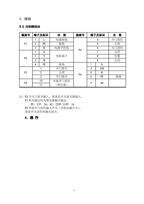
3、接线3-1 控制器接线注:P3开关门指令输入,要求是开关量无源输入。
P4所有输出均为继电器触点输出。
DC:24V,2A;AC:220V/110V 1A P5外接开门到位输入开关(双稳态磁开关),要求开关动作时触点闭合。
4.操作4-2 基本操作设定的基本操作方法如下所示。
这种方法用来设定开门总速度值从0.5m/s上升至0.7m/s,其它参数设定请参阅功能表。
4-3 系统参数可以通过前面板上的薄膜型按键改变和设定参数,以调节出所需要的开关门特性。
例如开关速度等。
被选定的参数号和设定的参数值通过四位LED显示屏显示出来。
同时可参看上页曲线图进行调整。
※注:设定参数时必须先断开开关门输入信号,否则按P键将不起作用。
如果间断性地按△或▽键,数值将一步一步地改变,如果长时间地按下这些键,数值将快速地改变。
如果出现不慎将参数错误设定,通过将参数F017设定为1,并按P键,可以将所有参数都复位到出厂设定值。
※注:参数F022—F032由厂方设定,一般情况下用户勿须现场设定。
6.调试说明6-1 两个关键词的解释1)脱机运行状态:脱开电梯主控制器、脱开层门装置,门机单独运行的状态。
2)外接开门到位开关:在门机底板上安装一双稳态磁开关、开关动作触点闭合,门机控制器得到开门到位信号,开门到位时通。
6-2、门机控制器调试的具体步骤1)按照顺序安装门机完毕,调整好门机高度和位置、轿门扇、门刀;让门机处于脱机运行状态,保证轿门无阻碍开门到位和关门到位。
2)检查门机控制器的输入电源:AC220V±15%;如电源电压不在AC220V±15%范围内,切勿上电,否则会损坏门机控制器。
3)确认输入电源电压正常,打开门机控制器电源开关。
初上电,门机控制器显示已存出厂门宽度脉冲数,以自学习速度向开门方向运行,直到外接开门到位开关闭合向门机控制器输入开门到位信号,同时操作面板上外接到位开关指示灯DSIN亮,表示门机已开门到位。
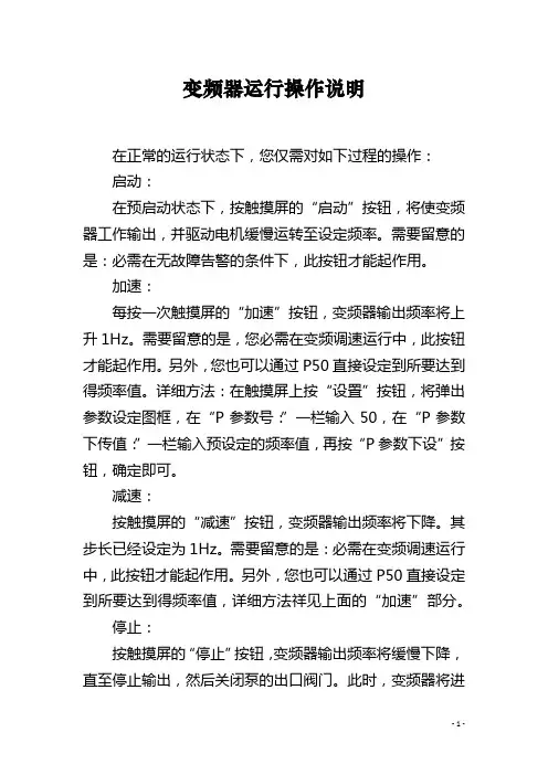
变频器运行操作说明在正常的运行状态下,您仅需对如下过程的操作:启动:在预启动状态下,按触摸屏的“启动”按钮,将使变频器工作输出,并驱动电机缓慢运转至设定频率。
需要留意的是:必需在无故障告警的条件下,此按钮才能起作用。
加速:每按一次触摸屏的“加速”按钮,变频器输出频率将上升1Hz。
需要留意的是,您必需在变频调速运行中,此按钮才能起作用。
另外,您也可以通过P50直接设定到所要达到得频率值。
详细方法:在触摸屏上按“设置”按钮,将弹出参数设定图框,在“P参数号:”一栏输入50,在“P参数下传值:”一栏输入预设定的频率值,再按“P参数下设”按钮,确定即可。
减速:按触摸屏的“减速”按钮,变频器输出频率将下降。
其步长已经设定为1Hz。
需要留意的是:必需在变频调速运行中,此按钮才能起作用。
另外,您也可以通过P50直接设定到所要达到得频率值,详细方法祥见上面的“加速”部分。
停止:按触摸屏的“停止”按钮,变频器输出频率将缓慢下降,直至停止输出,然后关闭泵的出口阀门。
此时,变频器将进入预启动状态。
停止后的变频器除检修维护需要断高压外,一般无需再断高压,可以重新按“启动”按钮启动变频器。
需要留意的是:第一,待电机完全停止后方可再次启动变频器;第二,变频器停止后,虽停止了输出,但自身仍待电,因此决不能打开变频器柜门,否则会有触电的危急。
篇2:变频器安全操作规程一、变频器的使用要点在使用变频器时,为确保变频器安全、高效、牢靠地运行,应留意以下几点:1.变频器接地端子必需牢靠接地,以有效抑制射频干扰,曾强系统牢靠性。
系统最好采用独立接地,接地电阻小于1欧。
系统中的传感器、I/O接口、屏蔽层等接地线,应与系统接地汇流排独立接地。
2.环境温度对变频器的使用寿命有很大的影响,环境温度每上升10度,变频器寿命就会减半。
因此变频器应置于有空气调整的环境里,温度应掌握在22度-28度,相对湿度RH≤70%-75%。
3.变频器调速系统的运行与停止不能使用断路器和接触器直接操作,而要用变频器掌握端子或变频器面板建来操作,否则或造成变频器端子失控,并可能造成变频器损坏。
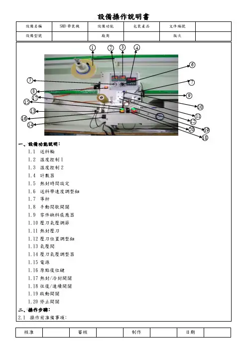

伦茨(Lenze)变频器8200Vector系列使用说明注:本说明适用于梳棉机FA231A所使用Lenze E82EV系列变频器包括内容:1.标准接线及安装1.1 400V控制器的主电源接线1.2 电机接线1.3符合EMC标准的安装1.4控制端子接线及说明2. 用操作面板进行参数设定2.1访问,设定所有参数2.2拷贝参数到操作面板2.3从操作面板复制参数到变频器2.4 输出转速的在线调整--用操作面板输入频率(hz)与其他给定值相加3.重要参数代码说明3.1 C0014代码可设置控制模式3.2 电机数据的输入/自动检测(C0087;C0088;C0089;C0090;C0091;C0084;C0092;C0148)3.3 JOG固定频率给定值(C0037,C0038,C0039)3.4 给定值选择(C0001)3.5 模拟输入给定的调整(C0026;C0027)3.6 PTC电机温度监控(C0119)3.7 数字输入信号配置(C0007)3.8 最小输出频率(C0010)3.9 最大输出频率(C0011)3.10 主加速时间(C0012)3.11主减速时间(C0013)3.12快停减速时间(C0105)3.13数字输入信号E1-E6电平反相(C0114)3.14 模拟量输入范围设定(C0034)3.15电流极限设定(C0022,C0023)4.故障诊断及排除4.1运行状态显示4.2故障查询5. 梳棉机FA231A变频器参数设定表5.1 E82EV222S4B参数设定表5.2 E82EV751S4B参数设定表6.变频器调试程序表7.产品维护,保养要点1.标准接线及安装1.1 400V控制器的主电源接线1.2 电机接线见上图注:BR1,BR2外部制动电阻T1,T2电机温度监控PTC热敏电阻或热继电器1.3符合EMC标准的安装注:将控制线及电源线与电机电缆分开使用低寄生电容电缆。
每单位长度电容值:●芯/芯≤75pF/m●芯/屏蔽层≤150pF/mEMC电缆密封垫按铭牌进行电机接线使用表面导电的安装板以尽可能大的导电表面将电缆屏蔽层连到PE上。
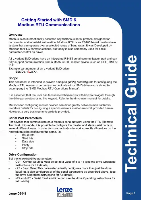
Getting Started with SMD &Modbus RTU CommunicationsOverviewModbus is an internationally accepted asynchronous serial protocol designed for commercial and industrial automation. Modbus RTU is an RS485 based master/slave system that can operate over a selected range of baud rates. It was Developed by Modicon for PLC communications, but today is also commonly used for basic parameter control on drives.All L variant SMD drives have an integrated RS485 serial communication port and can fully support communication from a Modbus RTU master device, such as a PC, HMI or PLC.Example part number of an L variant SMD drive:-ESMD371L2YXAScopeThis document is intended to provide a helpful getting started guide for configuring the Modbus RTU master to correctly communicate with a SMD drive and is aimed to accompany the “SMD Modbus RTU Operations Manual”.It is assumed that the user has familiarised themselves with how to navigate through the drive parameters using the keypad. Refer to the drive user manual for details. Methods for configuring master devices can differ greatly between manufacturers, therefore details for configuring a specific network master are NOT provided herein. However, a very basic generic guide is provided.Serial Port ParametersFor devices that communicate on a Modbus serial network using the RTU (Remote Terminal Unit) mode, it is possible to configure the master and slave serial ports in several different ways. In order for communication to work correctly all devices on the network must be configured the same, i.e.• Baud rate• Start bits• Data size• Parity• Stop bitsDrive ConfigurationSet the following drive parameters:-• C01 - Control Source: Must be set to a value of 8 to 11 (see the drive Operating Instructions for full details).• c25 - Baud Rate: This parameter actually configures more than just the drive baud rat, it also configures all of the serial parameters as described above. (see the drive Operating Instructions for full details).• n22 and n23 - Serial Fault and time out: see the drive Operating Instructions for full details).Modbus frame structureThe message structure for a Modbus message is as follows:-Address: • Size = 1 byte • Valid slave nodes addresses are in the range of 0 – 247 decimal, however,address 0 is reserved for use as a broadcast address. • The individual slave devices are assigned addresses in the range of 1 – 247,each slave node on the network must have an individual address, if two of more nodes have duplicate addresses this may prevent the network from functioning correctly. • A master addresses a slave by placing the slave address in the address field ofthe message. When the slave returns its response, it places its own address in the response address field to let the master know which slave is responding. Function Code • Size = 1 byte • The function code indicates what kind of action to perform. • The function code (depending upon the function) is normally followed by a datafield that contains request and response parameters. • The SMD supports function codes:-• 3 - Read Holding Registers* • 4 - Read Input Registers • 6 - Preset Single Register • 16 - Preset Multiple Registers** - Note: In general the SMD is limited in that it will only support Read and Write access to one register at a time. See the SMD Modbus Control Operation Manual section 2 for details and exceptions. Data • Master frame size = 4 bytes• 2 bytes for register number • 2 bytes for either number of register to read, or data to be written • Slave frame size = 3 or 4 bytes• 3 bytes for read response; data size in byte followed by the actual data(there is an exception to this which is detailed in the “SMD Modbus RTU Operations Manual”). • 4 bytes for a write response; which is a repeat of the original master datathat was written.Error Check • The Error checking field is the result of a "Cyclical Redundancy Checking" (CRC)calculation that is performed on the message contents. • For full details on how to calculate the CRC please refer to the official ModbusRTU specification.Modbus Registers• The “SMD Modbus Control Operation Manual” provides a complete list of many of which have a direct relationship to actual drive parameters.•For every drive parameter there is a corresponding Modbus register. However, in addition to these there also several additional registers that are only accessible through Modbus. All of these registers are detailed in the “SMD Modbus Control Operation Manual”.•To help clarify the statement in “SMD Modbus Control Operation Manual” section “2C”: Due to the way in which most Modbus masters typically access slave registers it may be necessary to add “1” to the SMD register number to ensure access to the correct register because the master automatically deducts “1” from the register number, e.g.C37 - Fixed setpoint1 is listed as register address 74 (for SMD PV507). To correctly access this address, the master actually needs to use register 40075, thereafter the master automatically deducts “1” during its message frame construction and will therefore really access drive register 40074. •Some Modbus Master devices have the option to use zero base addressing; de-selecting this will simply everything as all registers will then have the correct off-set, i.e. 1 to 1 register addressing.Drive Security• For read access no security has to be set as read only access is always granted (while C01 = 8 - 11).•Assuming that the drive password has not been activated, (see C94), writing a value of “0” to drive register 48 (40048) will unlock both drive control and parameter access.•If a password has been configured, then writing the password number to drive register 48 will again unlock access to both areas.Writing only “0” to drive register 48 after a password has been configured will then only unlock access to the drive control registers.• Parameter access can be unlocked independently by writing “0” to drive register 49•To re-activate / re-secure access to these areas simply set BIT-1 of the drive control register 1.ExamplesExample 1 - Reading Fixed Setpoint 1 (C37 default value of 20)Modbus Master request frame transmissionModbus Slave response frame transmissionExample 2 - Writing to a value of 12.3Hz to Fixed Setpoint 1 (C37)Modbus Master request frame transmissionModbus Slave response frame transmissionExample 3 - unlock security, enable drive and control the motor speedThe following drive parameters are assumed to have been already set:- • C01 = 11 (default value is 0) • C09 = 1 as per default • C94 = 0 as per default • Close terminal 20 and 281. Unlocking security, set a value of 0 to drive register 48Modbus Master frame transmission2. Set BIT-8 of the Control Word to select “Serial Speed Reference” Modbus Master frame transmission3.Set BIT-3 of the Control Word to enable the drive, the drive display will change Modbus Master frame transmission4.Set a value of 250 to the serial speed reference register 40. The drive display will change to display the output frequency which will be 25.0Hz. Modbus Master frame transmission5.Set BIT-2 of the Control Word to disable the drive, the drive display will change to “Inh” for inhibitModbus Master frame transmission。
伦茨E94AMHE0324变频说明书
(1)该变频调速装置为电力电子器件组成,在运输及安装过程中,尽量避免强烈的震动,尽量垂直运输。
(2)该变频调速装置尽量安装在干燥通风的区域,变频器的散热片距墙壁(或遮挡物)距离应大于1.0米。
(3)长期不用时,应存放在清洁干燥的地方;在井下安装好而不运行的状况下,该设备尽量不停电。
(4)使用之前,必须详细阅读用户手册。
(5)变频调速装置其隔爆外壳体及本安控制盒的结构和非本安及本安电路的电气参数,在出厂前均已装配调试合格,用户严禁改动变频调速装置壳体的结构和电气参数,以确保本产品的防爆性能、电气性能和本安性能。
(6)设备在带电情况下,严禁松动隔爆壳紧固件,在检修或处理故障时,请注意“断电源后开盖”。
(注:本安接线腔不受此限制)(7)外壳应接地良好。
(8)电源接线隔爆腔在接线时请注意按图接线,不得接错。
(9)装置防爆主腔内进行操作时,手上必须带接地导线或静电环。
(10)装置电源R、S、T停电以后5分钟内禁止对变频器隔爆主腔内的任意电路进行操作,且必须用仪表确认机内电容已放电完毕,方可实施机内作业。
停电以后1分钟内禁止再次给电。
(11)负载运行过程中尽量减少瞬时停电次数。
(12)禁止对变频器主回路及控制回路进行耐压试验,如对与变频有电路联系的相关设备进行耐压试验之前应将与变频相关的电路切断。
英威腾变频器说明书
1:正转运行(FWD)2:反转运行(REV)
当运行指令通道为端子控制时,变频器的运行命令由上述端子功能给定.
3、:三线式运行控制
三线控制输入端子,具体参见P5.07三线制功能码介绍
4:正转寸动5:反转寸动
具体寸动频率和加减速时间参见P3.06~P3.08的说明。
6:自由停车
命令有效后,变频器立即封锁输出,电机停车过程不受变频器控制,对于大惯量负载且对停车时间没有要求时,建议采用该方式,该方式和P1.08所述自由停车含义相同。
外部故障复位功能,用于远距离故障复位,与键盘上的STOP/RST键功能相同。
8:运行暂停
20:多段速暂停
屏蔽多段速选择端子功能,使设定值维持在当前状态。
21、22:加减速时间选择端子1、2
通过此两个端子的状态组合来选择4组加减速时间:
32:频率增减设定暂时清零
当端子闭合时,可清除UP/DOWN设定的频率值,使各定频率恢复到由频率指令通道给定的频率,当端子断开时重新回到频率增减设定后的频率值。
33~39:保留
设置S1~S4,HDI端子采样的滤波时间。
在干扰大的情况下,应增大该参数,以防止误操作。
23:简易PLC复位
重新开始简易PLC过程,清除以前的PLC状态记忆信息。
24:简易PLC暂停
PLC在执行过程中程序暂停,以当前速度段一直运行,功能撤销后,简易PLC继续运行。
25:PID控制暂停
PID暂时失效,变频器维持当前频率输出
26:摆频暂停
变频器暂停在当前输出,功能撤销后,继续以当前频率开始摆频运行。