Load balancing and communication optimization for parallel adaptive finite element computat
- 格式:pdf
- 大小:156.48 KB
- 文档页数:10
FLB:Fast Load Balancing for Distributed-Memory Machines Andrei R˘a dulescu Arjan J.C.van GemundFaculty of Information Technology and SystemsDelft University of TechnologyP.O.Box5031,2600GA Delft,The NetherlandsA.Radulescu,A.J.C.vanGemund@its.tudelft.nlAbstractThis paper describes a novel compile-time list-based task scheduling algorithm for distributed-memory systems,called Fast Load Balancing(FLB).Compared to other typical list scheduling heuristics,FLB drastically reduces scheduling time complexity to,where and are the number of tasks and edges in the task graph, respectively,is the task graph width and is the number of processors.It is proven that FLB is essentially equivalent to the existing ETF scheduling algorithm oftime complexity.Experiments also show that FLB performs equally to other one-step algorithms of much higher cost,such as MCP.Moreover,FLB consistently outperforms multi-step algorithms such as DSC-LLB that also have higher cost.1IntroductionScheduling heuristics exist for both bounded and un-bounded number of processors.Although attractive from a cost perspective,scheduling for an unbounded number of proces-sors is rarely of practical use,because the required number of processors is not usually available.Hence,their application is typically found within the multi-step scheduling method for a bounded number of processors[8,9].Alternatively,scheduling for a bounded number of proces-sors can be performed in a single ing this one-step approach,the results are usually better,but at a higher cost. Scheduling for a bounded number of processors can be done ei-ther using duplication(e.g.,DSH[4],BTDH[2]or CPFD[1]) or without duplication(e.g.,MCP[11],ETF[3],DLS[10]or FCP[7]).Duplicating tasks results in better scheduling per-formance but significantly increases scheduling cost.Non-duplicating task heuristics have a lower complexity and still obtain good schedules.However,when compiling large pro-grams for large systems,the complexity of current approaches is still prohibitive.This paper presents a new compile-time task scheduling algorithm,called Fast Load Balancing(FLB).We prove that given a partial schedule,FLB schedules at each iteration the This research is part of the Automap project granted by the Nether-lands Computer Science Foundation(SION)withfinancial support from the Netherlands Organization for Scientific Research(NWO)under grant number SION-2519/612-33-005.ready task that starts the earliest.The main idea is to keep the processors busy,in this respect being close to a load balancing scheme(hence the acronym).The same criterion is also used by ETF,however at a much higher complexity ofcompared to FLB’s com-plexity,where and are the number of tasks and edges in the task graph,respectively,is the task graph width,and is the number of processors.Experiments also show that FLB performs equally to existing one-step scheduling algorithms of much higher complexity such as MCP.Moreover,FLB consis-tently outperforms multi-step algorithms like DSC-LLB which also have higher cost.The paper is organized as follows:The next section spec-ifies the scheduling problem and introduces some definitions used in the paper.Section3briefly reviews some of the well-known scheduling algorithms for bounded number of proces-sors on which we base our comparisons.In Section4,the FLB algorithm is presented.Section5illustrates the functionality of the algorithm through an execution trace.Section6describes its performance.Section7concludes the paper.2PreliminariesA parallel program can be modeled by a directed acyclic graph,where is a set of nodes and is a set of edges.A node in the DAG represents a task,containing in-structions that execute sequentially without preemption.Each task has a weight associated with it,which represents the computation cost of executing the task.The edges correspond to task dependencies(communication mes-sages or precedence constraints).Each edge has a weight associated with it,which represents the communi-cation cost to satisfy the dependence.The communication to computation ratio()of a parallel program is defined as the ratio between its average communication cost and its aver-age computation cost.If two tasks are scheduled to the same processor,the communication cost between them is assumed to be zero.The task graph width()is defined as maximum number of tasks that are not connected through a path.A task with no input edges is called an entry task,while a task with no output edges is called an exit task.A task is said to be ready if all its parents havefinished their execution.Note that at any given time the number of ready tasks never exceeds .A task can start its execution only after all its messages have been received.As a distributed system we assume a set of processors connected in homogeneous clique topology.Inter-processor communication is performed without contention.Once scheduled,a task is associated with a processor ,a start time and afinish time.If the task is not scheduled,these three values are not defined.The processor ready time of a given processoron a partial schedule is defined as thefinish time of the last task scheduled on the given processor,according to.The enabling processor of a ready task,is the processor from which the last message arrives.The last message arrival time of a ready task is defined as.When task is tentatively scheduled to a processor,the messages sent by’s predecessors that are already scheduled to are assumed to take communication time.Therefore, the effective message arrival time will be.The esti-mated start time when scheduling a ready task to a processor is defined as.Given a partial schedule and a ready task is said to be of type EP if its last message arrival time is greater than the ready time of its enabling processor:.and of type non-EP otherwise.Thus,for EP type tasks start the ear-liest on their enabling processor.A processor is called active if there are EP type tasks for which it is the enabling processor and passive otherwise.The objective of the scheduling problem is tofind a schedul-ing of the tasks in on the processors in such that the paral-lel completion time(schedule length)is minimized.The paral-lel completion time is defined as.3Related WorkIn this section,three existing scheduling algorithms and their characteristics are described,namely the one-step scheduling algorithms MCP[11]and ETF[3],and the multi-step method DSC-LLB[8,12].3.1MCPMCP(Modified Critical Path)is a list scheduling algorithm in which task priorities are based on the latest possible start time of the tasks.The latest possible start time is computed as difference between the critical path of the graph and the longest path from the current task to any exit task.A path length is the sum of the execution times and the communication costs of the tasks and edges belonging to the path.A task with the smallest latest possible start time has the highest priority.Ties are bro-ken considering the priorities of the task’s descendents.The tasks are selected in the order of their priorities and scheduled on the processor that can execute it the earliest.The time com-plexity of MCP is.MCP is relatively fast compared with other one-step scheduling algorithms.Furthermore,its scheduling perfor-mance is shown to be superior compared to most of the other algorithms for bounded number of processors[5,8].MCP can be modified to run faster by choosing a random tie breaking scheme at a negligible loss of performance.In this case,the time complexity is reduced to. 3.2ETFETF(Earliest Task First)is a one-step scheduling algorithm in which at each iteration,the ready task that can start the ear-liest is scheduled.The earliest starting task is determined by tentatively scheduling all the ready tasks to all processors.The task with the minimum starting time is selected and scheduled to the corresponding processor on which it starts the earliest. The time complexity of ETF is.ETF has a high complexity because at each iteration,it is required to compute the start times of each task for every pro-cessor scheduling.The main idea behind ETF is to keep the processors busy,in this respect being close to a load balancing scheme.Its scheduling performance is shown to be comparable with MCP’s performance[5].3.3DSC-LLBDSC-LLB is a multi-step scheduling algorithm composed of DSC(Dominant Sequence Clustering)and LLB(List-Based Load Balancing).Thefirst step,using DSC,is intended to minimize communication by grouping the highly communi-cating tasks together in clusters.The second step,using LLB, maps the clusters to the existing processors and orders the tasks within the clusters.In the DSC algorithm,task priorities are dynamically com-puted based on the sum of their top level and bottom level.The top level and bottom level are the sum of the computation and communication costs along the longest path from the given task to an entry task and an exit task,respectively.Again,the com-munication costs are assumed to be zero between two tasks mapped to the same processor.While the bottom level is stat-ically computed at the beginning,the top level is computed incrementally during the scheduling process.The tasks are scheduled in the order of their priorities,where the largest sum of top and bottom levels takes priority.The destination proces-sor is either the processor from which the last message arrives, or a new processor depending on which the given task can start earlier.The time complexity of DSC is.In the LLB algorithm,a task is mapped to a processor if there is at least another task from the same cluster scheduled on that processor and not mapped otherwise.LLB is a load bal-ancing scheme.First,the destination processor is selected as the processor that becomes idle the earliest.Second,the task to be scheduled is selected.There are two candidates:(a)a task already mapped to the selected processor having the least bot-tom level,or(b)an unmapped task with the least bottom level. The one starting the earliest is scheduled.The time complex-ity of LLB is,where is the number of clusters obtained in the clustering step.DSC-LLB is a low-cost algorithm.Not surprisingly,com-pared to a higher cost scheduling algorithm as MCP,it has worse scheduling performance.However,the DSC-LLB out-put performance is still shown to be within of the MCP output performance,while outperforming other known multi-step scheduling algorithms[8].4The FLB AlgorithmAs mentioned earlier,list scheduling algorithms generally perform better compared to other scheduling algorithms for a bounded number of processors,such as multi-step methods[8]. Recently,a list scheduling algorithm,called FCP,has been proposed[7]whose time complexity is significantly reduced without sacrificing performance.For FCP,it has been proven that given a partial schedule and an arbitrary ready task,only two processors need to be considered tofind the minimum start time of the given task.However,given the partial schedule and the set of ready tasks,the selected task need not always be the preferred one(i.e.,the ready task that can actually start the ear-liest).In the FLB heuristic proposed in this paper,we improve this task selection by scheduling the ready task that can start the earliest.We prove that only two cases need to be consid-ered to indeed select the preferred task and its corresponding processor.The scheduling process is therefore improved,while the low time complexity is maintained.Note that FLB uses the same task selection criterion as in ETF.In contrast to ETF however,the preferred task is identi-fied in instead of.Although essentially sim-ilar,there is a small difference in the task selection scheme. Throughout the scheduling process it may happen that several ready tasks can start at the same earliest time.ETF an FLB have different criteria to break this tie,and as a consequence in some cases they may still select a different task-processor pair to be scheduled.Priority-based scheduling algorithms have three parts:(a) task priorities computation,(b)sorting tasks according to their priorities and(c)task puting task priorities takes at least time,since the whole task graph has to be traversed.Sorting tasks takes time.The variety of scheduling approaches refers to the last part(c).For most list scheduling algorithms,the task scheduling part takes time complexity caused by the fact that all processors are considered tofind the processor on which the current task can start the earliest.ETF[3]uses an even more elaborate approach.At each iteration,it schedules the ready task that can start the earliest to the processor on which this earliest start time is achieved.However,the complexity is higher(),caused by the fact that at each iteration all the tasks need to be considered in the selec-tion process.In[7]has been proven that processor selection in list scheduling algorithms can be performed at a considerable lower time complexity of.In this paper we go one step further and prove that even the stronger task selec-tion criterion used in the ETF scheduling algorithm can also be achieved at the same cost of.4.1Algorithm DescriptionIn FLB,at each iteration of the algorithm,the ready task that can start the earliest is scheduled to the processor on which that start time is achieved.To select the earliest starting task,pairs of a ready task and the processor on which it starts the earliest need to be considered.In order to obtain the earliest start time of a given ready task on a partial schedule,the given task must be scheduled either (a)to the processor from which the last message is sent from or(b)to the processor becoming idle the earliest(as proven in[7]).An informal explanation is that if the processor the last message is sent from is idle before that message is received, then the start time of the task can be improved by scheduling the task on that processor.If that processor is busy at the time the last message arrives,then the task cannot start earlier than the last message arrival time which ever processor is selected. Consequently,the task will start the earliest on the processor becoming idle the earliest.It follows that an EP type task starts the earliest on its enabling processor and a non-EP type task start the earliest on the processor becoming idle the earliest.Given a partial schedule,there are only two pairs task-processor that can achieve the minimum start time for a task: (a)the EP type task with the minimum estimated start timeon its enabling processor,and(b)the non-EP type task with the minimum last message arrival time on the processor becoming idle the earliest.The first case minimizes the earliest start time of the EP type tasks, while the second case minimizes the earliest start time of the non-EP type tasks.If in both cases the same earliest start time is obtained,the non-EP type task is preferred,because the com-munication caused by the messages sent from the task’s prede-cessors are already overlapped with the previous computation. Considering the two cases discussed above guarantees that the ready task with the earliest start time will be identified.A for-mal proof is given in the appendix.For each processor,there are two sorted lists storing the EP type tasks for which the given processor is the enabling pro-cessor.The tasks in thefirst list(EMT EP task l)are de-creasingly sorted by the effective message arrival time on their enabling processor().The tasks in the sec-ond list(LMT EP task l)are decreasingly sorted by their last message arrival time().The non-EP type tasks are also stored in a list(nonEP task l),decreasingly sorted by.For all three task lists,ties are broken by selecting the task with the longest path to any exit tasks.There is a list of active processors(active proc l),de-creasingly sorted by the minimum of the EP type tasks enabled by them.The minimum of the EP type tasks enabled by a processor is computed in as the maximum between of thefirst task in the processor’s EMT EP task l and the processor’s.A second global processor list(all proc l)stores all processors,decreas-ingly sorted by the.The FLB algorithm is formalized below.FLB()BEGINFORALL t DOIF t is an entry task THENSetEMT(t,0)SetLMT(t,0)Enqueue(nonEP_task_l,t,0)END IFEND FORALLFORALL p0TO P-1DOEnqueue(all_proc_l,p,0)END IFEND FORALLWHILE NOT all tasks scheduled DO(t,p)ScheduleTask();UpdateTaskLists(t,p)UpdateProcLists(t,p)UpdateReadyTasks(t,p)END WHILEENDAt the beginning,the set of ready tasks consists of the entrytasks.None of them satisfies the EP type condition.Conse-quently,they are stored in the non-EP type task list.Moreover,as there are no EP type tasks,there is no active processor andthe active processor list is empty.All the processors have theready time,so all of them have the same priority,,in theglobal processor list.The scheduling loop is repeated as long as there exist un-scheduled tasks.At each iteration,one task is scheduled us-ing ScheduleTask.After each task scheduling,the tasklists,the processor lists and the ready task set must be updated,according to the new conditions following the last schedulingstep.The four procedures FLB is based on Schedule-Task,UpdateTaskLists,UpdateProcLists and Up-dateReadyTasks are described below.ScheduleTask()BEGINp1Head(active_proc_l)IF p1NULL THENt1Head(EMT_EP_task_l[p1])END IFp2Head(all_proc_l)t2Head(nonEP_task_l)IF(p1NULL)(EST(t1,p1)<EST(t2,p2))THEN Schedule task t1on processor p1Dequeue(active_proc_l)Dequeue(EMT_EP_task_l[p1])RemoveItem(LMT_EP_task_l[p1],t1)RETURN(t1,p1)ELSESchedule task t2on processor p2Dequeue(all_proc_l)Dequeue(nonEP_task_l)RETURN(t2,p2)END IFENDThe ScheduleTask procedure selects two task-processorpairs for the scheduling step.Thefirst pair consists of the EPtype task with the minimum time and its enabling pro-cessor.The second pair is the non-EP task with the minimum and processor becoming idle the earliest.The pair which achieves the minimum start time is selected and the selectedtask is scheduled to the selected processor.Scheduling a taskalso implies assigning to it its corresponding processor,starttime andfinish time.The Dequeue and RemoveItem pro-cedures are used to remove the heads and the elements fromthe sorted lists,respectively.UpdateTaskLists(t,p)BEGINWHILE true DOt Head(LMT_EP_task_l[p])IF t=NULL THENBREAKEND IFIF LMT(t)PRT(p)THENBREAKDequeue(LMT_EP_task_l[p])RemoveItem(EMT_EP_task_l[p],t)Enqueue(nonEP_task_l,t,LMT(t))END WHILEENDAfter scheduling a task to a processor,the processor’s readytime changes.Consequently,some of the EP type tasks enabledby that processor may no longer satisfy the condition to be of EP type.UpdateTaskLists moves the tasks that no longersatisfy the EP type condition to the non EP type task list.Thetasks are tested in the order of their.Finally,if there are no more EP type tasks enabled by the given processor,theprocessor is removed from the active processor list.UpdateProcLists(t,p)BEGINt Head(EMT_EP_task_l[p])IF t=NULL THENRemoveItem(active_proc_l,p)ELSEprio EST(t,p)BalanceList(active_proc_l,p,prio)END IFENDUpdateProcLists updates the active processor list.If there is no EP type task enabled by the given processor,the processor must be removed from the active processor list.If there are still EP type tasks enabled by the given processor they may not be the same and as a consequence the processor pri-ority in the active processor list could be modified.Therefore, the processor priority and the active processor list must be up-dated.Also,the global processor list must be updated because the current processor has changed the time it becomes idle. UpdateReadyTasks(t,p)BEGINFORALL t’Succ(t)DOIF Ready(t’)THENp’GetEnablingProc(t’)ComputeLMT(t’)ComputeEMT(t’,p’)IF LMT(t’)<PRT(p’)THENEnqueue(nonEP_task_l,t’,LMT(t’))ELSEIF Head(EMT_EP_task_l[p’])=NULL THENprio EST(t’,p’)Enqueue(active_proc_l,p’,prio)ELSEt’’Head(EMT_EP_task_l[p’])IF EMT(t’,p’)<EMT(t’’,p’)THENprio maxEMT(t’),PRT(p’)BalanceList(active_proc_l,p,prio)END IFEND IFEnqueue(EMT_EP_task_l[p’],t’,EMT(t’,p’))Enqueue(LMT_EP_task_l[p’],t’,LMT(t’))END IFEND IFEND FORALLENDUpdateReadyTasks adds the tasks that become ready due to the current task scheduling to one of the ready task lists, depending if it is of type EP or not.Moreover,if the task is of type EP,its enabling processor may become active and it must be added to the active processor list.Also,if the processor is already active and its priority changes,the active processor list must be updated.4.2Complexity AnalysisThe complexity of the FLB algorithm is as follows.To com-pute task priorities throughout the algorithm,all the tasks and dependencies must be considered once.Consequently,the total complexity of computing task priorities takes time.Scheduling a task involves a comparison between two ten-tative task scheduling operations.The decision is taken basedFigure1.Example task graphon the two estimated start times of the tasks tentatively puting the estimated start times takes time, since the estimated start times are computed as the maximum of the task effective message arrival time on that processor on the one hand and the processor ready time on the other hand. These values are already computed at the time the decision is made.Since there are tasks,the resulting task scheduling complexity is.Task lists operations are adding and removing tasks from sorted lists.Every task is added and removed at most once from the two lists of EP type tasks and once from the non-EP type task list.Since there are at most ready tasks at any moment in time,a list operation takes time.As there are tasks,the total complexity of maintaining task lists is.At each scheduling iteration,the global processor list changes,because the processor ready time changes for the des-tination processor of the scheduling.As a consequence,an op-eration time complexity must be performed,which implies a total complexity for maintaining the global processor list of.After becoming idle or being scheduled,a task may change the active or passive status of a processor or its priority in the active processor list.As a consequence,a total complexity of is required to maintain the active processor list.Finally,the cost offinding ready tasks takes time, since all the tasks and edges must be scanned throughout the algorithm.In conclusion,the total time complexity of the FLB algo-rithm is.5Execution TraceIn this section,we illustrate the steps of the FLB algorithm by scheduling the task graph in Fig.1on two processors.The execution trace of the FLB algorithm is presented in Table1. Thefirst two columns in the table list the EP type tasks enabled by and,respectively,as they are sorted in the correspond-ing lists.The task’s and bottom level are included to illustrate their sorting order,as well as their to moti-vate their EP type.The third column in the table lists the non-EP tasks non-EP Scheduling on on tasksEMT BL LMT LMT ST FT,,,,,,,,Table1.Execution trace of the FLB algorithm. EP type tasks sorted by.Finally,the last column showsthe scheduling at the current iteration,including the task’s starttime andfinish time.At the beginning,there is only one ready task,namely. It is of non-EP type as it has no enabling processor.Taskis scheduled on one randomly selected processor,as all the processors have zero workload.After scheduling,three tasks become ready,namely, and.As there are no non-EP type tasks,the active processor accommodating the earliest starting EP type task is selected, in this case being the only active processor.The EP type task with the higher priority is selected.Since the is the same for all three tasks,the tie breaking mechanism stipulates that the task with the higher bottom level be selected and scheduled.After scheduling,becomes non-EP type,because becomes larger than.The other ready task still satisfies the EP type condition.The two task-processor pairs to be compared for the next scheduling iteration are now -and-.Processor is selected for the latter,because it is the processor becoming idle the earliest.Thus,-is selected since is lower than.Two other tasks become idle:and,both of type EP, enabled by and,respectively.There are no non-EP tasks, so thefirst starting EP type task is selected and scheduled to its enabling processor.Task becomes non-EP type and is moved to the non-EP type task list.Task becomes ready and of EP type,so it is stored to the EP task list of its enabling processor.Thefirst starting EP type task is which starts on at.The non-EP task with the lowest,,starts on the processor becom-ing idle the earliest,,at.Consequently,is scheduled on at.At the next iteration both EP type and non-EP type tasks, namely and,respectively,start at the same time:7.The non-EP type task is preferred and scheduled on.In each of the next two iterations,no choice need be made as there is only one task to be scheduled.First is scheduled on at,then is scheduled on at.Figure 2.Scheduling algorithm costs6Performance ResultsThe FLB algorithm is compared with three algorithms,namely MCP,ETF,and DSC-LLB.The three algorithms are well-known,use different scheduling schemes,and were shown to obtain competitive results [5,8,11].We selected the lower-cost version of MCP,in which if there are more tasks with the same priority,the task to be scheduled is chosen ran-domly.We consider task graphs representing various types of par-allel algorithms.The selected problems are LU decomposi-tion (“LU”),Laplace equation solver (“Laplace”)and a stencil algorithm (“Stencil”).For each of these problems,we adjusted the problem size to obtain task graphs of aboutnodes.For each problem,we varied the task graph granu-larities,by varying the communication to computation ratio().The values used for were 0.2and 5.0.For each problem and eachvalue,we generated 5graphs with random execution times and communication delays (i.i.d.,uni-form distribution with unit coefficient of variation).A larger set of problems and granularities has been used to measure the FLB’s performance in [6].6.1Running TimesOur main objective is to reduce task scheduling cost (i.e.,running time),while maintaining performance.In Fig.2the average running time of the algorithms is shown in CPU seconds as measured on a Pentium Pro/233MHz PC with 64Mb RAM running Linux 2.0.32.ETF is the most costly among thecompared algorithms.Its running time increases fromms forup to s for .MCP also increases its running times with the number of processors,but its cost issignificantly lower.For,it runs for ms,while for ,the running time is ms.DSC-LLB does not varysignificantly with ,as its most costly step,clustering,is inde-pendent of the number of processors.The DSC-LLB runningtimes vary aroundms.FCP achieves the lowest running time,varying fromms forto ms for .FLB running time is at the same level compared to FCP.It increases from ms for up to ms for .The FLB’s actual running times are comparable to FCP’s running times,despite the fact that theFLB’s complexity ofis highercompared to FCP’s complexity of.This is due to the fact that usually,the width of the task graph has reasonable low values.CCR =0.2Laplace CCR =5.0Figure 3.FLB speedup6.2Scheduling PerformanceIn Fig.3we show the FLB speedup for the considered prob-lems.For all the problems,FLB obtains significant speedup.There are two classes of problems:(a)Stencil and FFT which achieve linear speedup and (b)LU and Laplace for which there less speedup is obtained for large number of processors.Sten-cil and FFT are more regular.Therefore more parallelism can be exploited and better speedup is obtained.For LU and Laplace,there are a large number of join operations.As a consequence,there is not much parallelism available and the speedup is lower.To compare the FLB algorithm with the other algorithms,we use the normalized schedule lengths (),which is de-fined as the ratio between the schedule length of the given al-gorithm and the schedule length of MCP.In Fig.4we show the average normalized schedule lengths for the selected algorithms and problems.For each of the con-sideredvalues a set of values is presented.MCP and ETF consistently yield relatively good schedules.Depending on the problem and granularity,either one or the other performs better.The differences become larger for fine-grained problems,which are more sensitive to scheduling deci-sions.For LU,MCP schedules are up tobetter,while for Laplace,ETF schedules are up tobetter.For coarse-grain problems,the results are comparable.DSC-LLB is a multi-step method intended to obtain ac-ceptable results while aiming for minimum complexity.Its scheduling performance is not much worse compared to MCP and ETF.Typically,the schedule lengths are no more thanlonger than the MCP and ETF’s schedule lengths.Althoughin some cases the difference can be higher (up to)there are also cases in which DSC-LLB performs better (up to)compared to a list scheduling algorithm.FCP has both low-cost and good performance.FCP ob-tains comparable performance with MCP,because it uses the same scheduling criteria as MCP,but in a more efficient pared to ETF,the overall performance is also com-parable.However the differences between FCP and ETF (upto)are higher compared to the differences between FCP and MCP ().Finally,compared to DSC-LLB,FCP obtains consistently better performance.FLB has both low-cost and good performance.FLB obtains。

Data SheetKey SpecificationsKey Features•2x2 MU-MIMO with two spatialstreams per radio•Third 2x2 MIMO radio for dedicated RFand WIPS scanning•802.11ac Wave 2 support •Up to 400 Mbps for 2.4 GHz radio •Up to 867 Mbps for 5 GHz radio •Integrated omnidirectional antennas •20/40/80 MHz channel width support •Integrated BLE •2x Gigabit Ethernet port•Full Operational Capacity with 802.3atPoE+•Distributed Data Plane architecture •Zero-touch deployment through automatic cloud activation and configuration •Cloud or on premises management plane options •Operating modes for dedicated access, dedicated security or dual-mode •Support for up to 8 distinct SSIDs per radio •Integrated firewall, traffic shaping, QoS and BYOD controls per SSID •Dynamic RF optimization through smart steering, band steering and optimal channel selection •Application visibility through layer 7 deep packet inspection •Automated device access logging •Patented Marker Packettm technology for rogue AP detection and classification •Wired VLAN monitoring for “No-WiFi” zone enforcement •Third party analytics integration with real-time data transfer •Self-healing wireless mesh networkingTop Performance at the Best PriceArista W-118 is an enterprise-grade 2x2 MU-MIMO tri-radio 802.11ac wall plate access point with dual concurrent 5 GHz and 2.4 GHz radios supporting 802.11a/n/ ac Wave 2, 802.11b/g/n, two spatial streams, and data rates of up to 876 Mbps and 300 Mbps, respectively. It also contains a third 2x2 MIMO 802.11ac radio for dedicated multi-function scanning and a fourth 2.4 GHz Bluetooth Low Energy (BLE) radio.Why Choose the W-118?The W-118 provides best value amongst high-performing, modern wall plate access points designed for cost conscious organizations. Built using the latest 802.11ac Wave 2 chipsets, the W-118 is perfect for medium density environments looking for the high performance and advanced features of current accesspoints without the high cost. Common deployment scenarios include small and medium schools, distributed remote offices, small meeting rooms, and enterprise campuses.The W-118 provides access to advanced access point features like role-based firewalls and application visibility without the high cost typically associated with Wave 2 devices. The W-118 is also a perfect fit for organizations in need of future-ready dedicated security sensorsiBeacon Bluetooth Low Energy SupportThe Arista W-118 supports the iBeacon Bluetooth Low Energy (BLE) standard. BLE is used for proximity based services on mobile devices via an application ecosystem. W-118 can be configured to advertise a unique identifier through iBeacons at a periodic interval.Arista Cloud Managed WiFiThe W-118 is managed by the Arista cloud and leverages a purpose-built cloud architecture to produce enterprise-grade wireless networks for every application required, ensuring high reliability through an approach that is automated, scalable, secure and cost effective.What Really MattersThe future of WiFi requires intelligent, self-reliant access points that support high-performing, highly reliable networks without the need for antiquated controllers. This approach removes the complexity, instability and high costs associated with enterprise WiFi today.Arista W-118AccessThe W-118 creates WiFi networks that require less time and resources to deploy and maintain compared to traditional devices, resulting in significant cost savings.• Plug and play provisioning using either Cloud or On-premise deployments - Arista Access Points take less than two minutes to activate and configure after connecting to the cloud• Support for up to eight individual SSIDs per radio providing maximum flexibility in network design• Network controls like NAT, Firewall and QoS implemented at the Access Point, ensuring faster and more reliable networks• Continuous scanning of all 2.4 GHz and 5 GHz channels by a dedicated 2x2 third radio provides a dynamic, 360 degree view of the RF environment to assist in RF optimization and client handling• Network availability and performance assurance using the third radio as a client to conduct on-demand and scheduled connectivity and performance tests• Smart steering addresses sticky client issues by automatically pushing clients with low data rates to a better access point• Band steering manages channel occupancy, pushing clients to the 5 GHz channel for optimal throughput• Smart load balancing distributes load evenly across neighbouring APs to optimize the use of network resources• Arista Wi-Fi’s distributed data plane architecture continues to serve users and secure the network even if connection with the management plane is interrupted• Interference avoidance from LTE/3G small/macro cells in commonly used TDD/FDD frequency bandsSecurityThe W-118 offers complete visibility and control of the wireless airspace that keeps the integrity of the network in check and actively protects users without manual intervention.•W-118 is equipped with industry leading fully integrated wireless intrusion prevention capabilities•Multifunction third radio provides uninterrupted spectrum scanning or client emulation for always on security coverage alongside dedicated 2.4G/5G client radios.•Arista’s patented Marker PacketsTM help accurately detect rogue access points on any network while minimizing false positives •Third radio used as a dedicated security sensor for 24x7x365 scanning and automated over-the-air (OTA) prevention •Deterministic rogue AP detection and prevention by monitoring all WiFi and non-WiFi VLANs.•Over-the-air and on-the-wire prevention techniques assure automatic and reliable threat prevention to keep unauthorized clientsand rogue APs off the network without impacting authorized connections.•Access Points autonomously scan for wireless threats and enforce security policy even if disconnected from the cloud management plane•VLAN monitoring enables a virtual connection to non-WiFi networks for complete network rogue detection and prevention AnalyticsThe W-118 collects massive amounts of data and supports immersive guest network experiences that develop and reinforce the relationship between them and the brand.• Reports of customer footfall, demographic, loyalty and other analytics provide insightful and actionable information.• Supports proximity marketing programs that trigger when certain devices are present, which includes automatic messaging vis MMSin-browser notifications and real time notifications sent to 3rd party systems that alert to the presence of enrolled devices.Property SpecificationPhysical Dimensions186.4mm X 123.9mm X 25.5mm / 7.3” X 4.9” X 1”Weight .455kg (1 lb)Operating Temperature 0o C – 40o C (32o F – 104o F)Storage Temperature -25o C – 75o C (-13o F – 167o F)MTBF535,205 hr @ 40o C1,081,559 hr @ 25o CHumidity0%-95% non-condensingP ower consuption11.8W (max) / 5.1W (min) / 8.3W (avg)Chipset Qualcomm QCA4019 SOCProcessor RAMQualcomm IPQ4019 717MHz quad core ARMprocessor with 512 MB RAM and 32 MB Flash Physical SpecificationsPort Description Connector Type Speed/ProtocolPower12V 2A5.5mm overalldiameter/2.1mmcenter pin/holePass-throughportThe pass-through port is used to pluga device into another wired port thatis available on the wall where the AP isinstalled. The pass-through port at therear of the device and pass-throughport on the bottom of the device areinternally connected.RJ-45--Ethernet(LAN3/PSE)Gigabit Ethernet port that can be usedfor wired extension for an SSID. Thisport also provides the power for thedevice using the 802.3af standardRJ-4510/100/1000 MbpsGigabit EthernetEthernet(LAN2/LAN1)Gigabit Ethernet port that can be usedfor wired extension for an SSID.RJ-4510/100/1000 MbpsGigabit EthernetReset Reset to factory default settingsPin hole pushbuttonHold down andpower cycle thedevice to resetOperational Specifications Port DescriptionConnectorTypeSpeed/Pro-tocol PassthroughThis is a wired port that facilitatesextension of the wired network after theAP is mounted on the wall. Another devicecan be plugged in to the pass-through porton the bottom of the W-118 device. Thetraffic on the pass-through port does notinterfere with the AP traffic. No policies canbe applied on the pass-through port traffic.RJ-45-WANEnables the connection to wired LANthrough a switch or hub. The device canthen communicate with the server. Thisport also provides the power for the deviceusing the 802.3af standardRJ-4510/100/1000Mbps EthernetPower overEthernetInput Power12V DC 2ANumber of Radios 3 WiFi Radios: One 2.4 GHz and 5 GHz radio each for simultaneous dual band client access. Athird dual-band radio dedicated to non-access smart scanning; WIPS, RF optimization, Remote Troubleshooting, and network assurance functions.1 BLE Radio: A fourth Bluetooth Low Energy radio for proximity based services on mobile devices via an application ecosystem.Max Clients Supported512 clients per radio (dependent upon use cases)MIMO2x2 for 2.4/5GHz RadiosNumber of Spatial Streams 2 for 2.4/5GHz RadiosRF Transmit Power20 dBm per radio chain (max); Actual power for Tx will depend on Country Regulatory Domain Simultaneous MU-MIMO Clients Two 1x1 MU-MIMO clientsUsers in a MU-MIMO group with a2x2 client1Bandwidth Agility YesFrequency Bands 2.4-2.4835 GHz, 4.9-5.0 GHz, 5.15-5.25 GHz (UNII-1), 5.25-5.35 GHz, 5.47-5.6 GHz,5.650-5.725 GHz (UNII-2), 5.725-5.85 GHz (UNII-3)Dynamic Frequency Selection Supported in compliance to all latest amendments from FCC, CE, IC, CB, TELEC, KCC regarding certifications.Frequency, Modulation and Data RatesIEEE 802.11b/g/nFrequency BandScanning TransmissionAll regionsUSA & Canada(FCC/IC)Europe(ETSI) 2400 ~ 2483.5 MHz2400 ~ 2473.5 MHz2400 ~ 2483.5 MHzModulation Type DSSS, OFDMPeak Data Rates Up to 300 Mbps (MCS 0-15)Antenna Integrated modular high efficiency PIFA antenna x4 (peak gain 5.0 dBi)IEEE 802.11a/n/acFrequency Band Scanning TransmissionAll regions USA & Canada(FCC/IC)Europe(ETSI)4.92 ~5.08 GHz5.15 ~ 5.25 GHz 5.25 ~ 5.35 GHz 5.47 ~ 5.725 GHz 5.725 ~ 5.825 GHz 5.15 ~ 5.25 GHz5.25 ~ 5.35 GHz5.725 ~ 5.825 GHz5.15 ~ 5.25 GHz5.25 ~ 5.35 GHz5.47 ~ 5.725 GHzDynamic Frequency Selection DFS and DFS2Modulation Type OFDMPeak Data Rates Up to 867 Mbps (MCS 0-15)Antenna Integrated modular high efficiency PIFA antenna x4 (peak gain 5.0 dBi)Maximum Aggregate Transmit PowerFor 2.4 GHzMCS Index Transmit Power(dBm)802.11b1 Mbps -11 Mbps22802.11g6 Mbps - 48 Mbps2554 Mbps802.11n HT20MCS 0,1,2,3,4,524802.11n HT40MCS 0,1,2,3,4,5 24For 5 GHzMCS Index Transmit Power(dBm)802.11a6 Mbps - 48 Mbps26.802.11n HT20MCS 0,1,2,3,4,526802.11n HT40MCS 0,1,2,3,4,526802.11ac VHT80MCS 0,1,2,3,4,5,6,726Note:The actual transmit power will be the lowest of:• Value specified in the Device Template• Maximum value allowed in the regulatory domain • Maximum power supported by the radioData Sheet Receive SensitivityFor 2.4 GHzMCS Index Receive Sensitivity (dBm)802.11g6 Mbps -9224 Mbps -36 Mbps -48 Mbps -54 Mbps -75802.11n HT20MCS 0, 8 -92MCS 1,9MCS 2,10MCS 3,11MCS 4.12MCS 5,13MCS 6,14MCS 7, 15 -73802.11n HT40MCS 0, 8 -89MCS 1,9MCS 2,10MCS 3,11MCS 4,12MCS 5,13MCS 6,14MCS 7, 15 -71.5 For 5 GHzMCS Index Receive Sensitivity (dBm)802.11a6 Mbps -9024 Mbps36 Mbps48 Mbps54 Mbps -74.5802.11n HT20MCS 0, 8 -90MCS 1,9MCS 2,10MCS 3,11MCS 4,12MCS 5,13MCS 6,14MCS 7,15 -73802.11n HT40MCS 0, 8 -88.5MCS 1,9MCS 2,10MCS 3,11MCS 4,12MCS 5,13MCS 6,14MCS 7, 15 -70For 5 GHzMCS Index Receive Sensitivity (dBm)802.11n VHT20MCS 0 -90MCS 1MCS 2MCS 3MCS 4MCS 5MCS 6MCS 7MCS 8 -69802.11n VHT40MCS 9-65802.11n VHT80MCS 0 -85.5MCS 1MCS 2MCS 3MCS 4MCS 5MCS 6MCS 7MCS 8MCS 9 -61Data Sheet5 GHz2.4 GHzInternal Antenna Radiation Patterns Internal Antenna Radiation Patterns dBi gaindBi gainData SheetHeadquarters5453 Great America Parkway Santa Clara, California 95054408-547-5500Copyright 2020 Arista Networks, Inc. The information contained herein is subject to change without notice. Arista, the Arista logo and EOS are trademarks of Arista Networks. Other product or service names may be trademarks or service marks of others.Support******************408-547-5502866-476-0000Sales****************408-547-5501866-497-0000Ordering Information : Access Point Power Part Number DescriptionAP-W118-SS-5Y W-118 2x2:2 tri radio 802.11ac Wave-2 wall plate access point with internal antennas and 5 year Cognitive Cloud SW SubscriptionAP-W118-SS-3Y W-118 2x2:2 tri radio 802.11ac Wave-2 wall plate access point with internal antennas and 3 year Cognitive Cloud SW SubscriptionAP-W118W-118 2x2:2 tri radio 802.11ac Wave-2 wall plate access point with internal antennas Part Number DescriptionPWR-AP-W4Universal AC power supply for all APs except for C-110PWR-AP-PLUS-NA One port 802.3at PoE+ injector for use with all Access Point models. Includes USA power cord. Not for outdoor use.”PWR-AP-W2Universal AC power supply for C-120, C-130, W-118 and C-100October 1, 2020Regulatory Specifications RF and ElectromagneticCountry CertificationUSA FCC Part 15.247, 15.407EuropeCE EN300.328, EN301.893Countries covered under Europe certification: Austria, Belgium, Cyprus, Denmark, Estonia, Finland, France,Germany, Greece, Hungary, Ireland, Italy, Iceland, Luxembourg, Latvia, Lithuania, Malta, Netherlands, Norway,Poland, Portugal, Spain, Sweden, Slovakia, Slovenia, Switzerland, The Czech Republic, UK.CountryCertificationUSA UL 60950CanadacUL 60950European Union (EU)EN 60950, RoHSSafety*For complete country certification records, please visit the site: https:///en/support/product-certificate AP-W118-R WW-118-R W 2x2:2 tri radio 802.11ac Wave-2 wall plate access point with internal antennas (bundled with Stand, Power supply, Ethernet cable)PWR-AP-W3Non-discountable purchase. Universal AC power supply for W-118, C-120, C-130 and C-100, 12VDC, 2A, Center +, DC Plug 5.5mm*2.1mm*L9.5mm, US UK Euro AU Plugs。

Ora-00600 错误的代码含义及常用查询
ora-600是Oracle对于一些内部错误的一个统一的错误号(类似的还有
ora-7445)。
要判断ora-600错误具体的类型,一般要根据其第一个参数来区分。
一个ora-600的例子如下:
ORA-00600: internal error code, arguments: [15700], [3], [0x1DDE1AAB0], [], [], [], [], []
其中15700代表这个错误的具体类型,这是和并行查询相关的一个内部错误,后面的几个参数则是该错误的一些具体参数,不同类型的错误,参数的意义也不尽相同。
ora-600一共有两大类,一类的错误类型以数字标识,另外一类则以字符串标识。
数字表示不同的内核层,而字符串则是具体的函数或者模块名。
在Metalink的Doc ID: 175982.1中,oracle列举了这两类错误的详细信息,转录在这里以供需要是查询:
援引Metalink 文档175982.1中,列举Ora-600错误代码供参考:
数字类型的Ora-600
字符串类型的Ora-600。


Maximum Load Balancing with Optimized LinkMetricsTouraj Shabanian;Massoud Reza Hashemi;Ahmad Askarian【期刊名称】《软件工程与应用(英文)》【年(卷),期】2012(5)12【摘要】Traffic engineering helps to use network resources more efficiently. Network operators use TE to obtain different objectives such as load balancing, congestion avoidance and average delay reduction. Plane IP routing protocols such as OSPF, a popular intradomain routing protocol, are believed to be insufficient for TE. OSPF is based on the shortest path algorithm in which link weights are usually static value without considering network load. They can be set using the inverse proportional bandwidth capacity or certain value. However, Optimization theory helps network researchers and operators to analyze the network behavior more precisely. It is not a practical approach can be implemented in traditionalprotocol .This paper proposes that to address the feasibility requirements, a weight set can be extracted from optimization problem use as a link metric in OSPF. We show the routes that selected in OSPF with these metric distribute the traffic more close to optimal situation than routes from OSPF with default metric.【总页数】6页(P14-19)【关键词】Component;Formatting;Style;Styling;insert【作者】Touraj Shabanian;Massoud Reza Hashemi;Ahmad Askarian【作者单位】Department of Electrical and Computer Engineering, Isfahan University of Technology, Isfahan, Iran【正文语种】中文【中图分类】R73【相关文献】1.Optimization for Maximum Nonlinear Buckling Load and Topics on Imperfection of Latticed Shells [J], Pei-Shan Chen;;;;;;;;;;;;;;;;2.Optimization of structural parameters for spatial flexible redundant manipulators with maximum ratio of load to mass [J], ZHANG Xu-ping;YU Yue-qing3.Optimization of Load Balancing Algorithm for Virtual Machine Dynamic Migration under Mobile Cloud Computing [J], Weijin Jiang;FangYe;Shengjie Yang;Wei Liu;Xiaoliang Liu;Sijian Lv4.The Configuration Optimization for Multilimbed Robots with the Viewpoint of Maximum Loading Capacity [J],5.Multi-objective design optimization of composite submerged cylindrical pressure hull for minimum buoyancy and maximum buckling load capacity [J], Muhammad Imran;Dong-yan Shi;Li-li Tong;Ahsan Elahi;Hafiz Muhammad Waqas;Muqeem Uddin因版权原因,仅展示原文概要,查看原文内容请购买。
软考高级架构师系统设计40题1. In a system design, which of the following is the most important consideration for scalability?A. Hardware performanceB. Software architectureC. Network bandwidthD. User interface design答案:B。
解析:软件架构对于系统的可扩展性至关重要。
硬件性能在一定程度上影响,但不是最关键的。
网络带宽主要影响数据传输,对可扩展性的直接影响较小。
用户界面设计与系统的可扩展性关系不大。
2. When designing a system, which principle should be followed to ensure high availability?A. RedundancyB. Minimization of componentsC. Simple architectureD. Low cost答案:A。
解析:冗余是确保高可用性的重要原则。
减少组件可能会降低复杂性,但不一定能保证高可用性。
简单架构有助于理解和维护,但不是保证高可用性的关键。
低成本通常不是高可用性设计的首要考虑因素。
3. Which of the following is a key factor in determining theperformance of a system?A. The number of usersB. The algorithm usedC. The color scheme of the interfaceD. The brand of the hardware答案:B。
解析:算法的优劣直接决定了系统的性能。
用户数量会影响系统负载,但不是决定性能的根本因素。
界面的颜色方案与性能无关。
硬件品牌对性能有一定影响,但算法的影响更为关键。
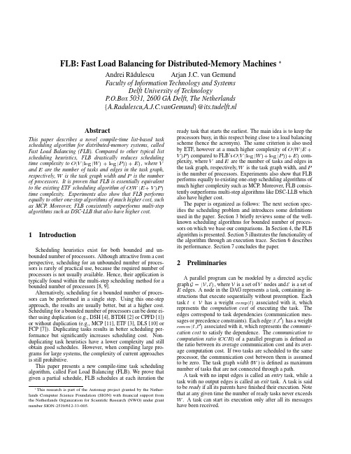
104IEEE JOURNAL ON SELECTED AREAS IN COMMUNICATIONS, VOL. 23, NO. 1, JANUARY 2005Balancing Transport and Physical Layers in Wireless Multihop Networks: Jointly Optimal Congestion Control and Power ControlMung ChiangAbstract—In a wireless network with multihop transmissions and interference-limited link rates, can we balance power control in the physical layer and congestion control in the transport layer to enhance the overall network performance while maintaining the architectural modularity between the layers? We answer this question by presenting a distributed power control algorithm that couples with existing transmission control protocols (TCPs) to increase end-to-end throughput and energy efficiency of the network. Under the rigorous framework of nonlinearly constrained utility maximization, we prove the convergence of this coupled algorithm to the global optimum of joint power control and congestion control, for both synchronized and asynchronous implementations. The rate of convergence is geometric and a desirable modularity between the transport and physical layers is maintained. In particular, when congestion control uses TCP Vegas, a simple utilization in the physical layer of the queueing delay information suffices to achieve the joint optimum. Analytic results and simulations illustrate other desirable properties of the proposed algorithm, including robustness to channel outage and to path loss estimation errors, and flexibility in trading off performance optimality for implementation simplicity. This paper presents a step toward a systematic understanding of “layering” as “optimization decomposition,” where the overall communication network is modeled by a generalized network utility maximization problem, each layer corresponds to a decomposed subproblem, and the interfaces among layers are quantified as the optimization variables coordinating the subproblems. In the case of the transport and physical layers, link congestion prices turn out to be the optimal “layering prices.” Index Terms—Congestion control, convex optimization, crosslayer design, energy-aware protocols, Lagrange duality, power control, transmission control protocol, utility maximization, wireless ad hoc networks.I. INTRODUCTIONWE CONSIDER wireless networks with multihop transmissions and interference-limited link rates. In order to achieve high end-to-end throughput in an energy efficient manner, congestion control and power control need to be jointly designed and distributively implemented. Congestion control mechanisms, such as those in transmission control protocol (TCP), regulate the allowed source rates so that the total traffic load on any link does not exceed the available capacity. At the same time, the attainable data rates on wireless links depend on the interference levels, which in turn depend onManuscript received October 14, 2003; revised August 27, 2004. The author is with the Electrical Engineering Department, Princeton University, Princeton, NJ 08544 USA (e-mail: chiangm@). Digital Object Identifier 10.1109/JSAC.2004.837347the power control policy. This paper proposes and analyzes a distributed algorithm for jointly optimal end-to-end congestion control and per-link power control. The algorithm utilizes the coupling between the transport and physical layers to increase end-to-end throughput and energy efficiency in a wireless multihop network. Congestion avoidance mechanisms in TCP variants have recently been shown to approximate distributed algorithms that implicitly solve network utility maximization problems. Traditionally, this class of optimization problems are linearly constrained by link capacities that are assumed to be fixed quantities. However, network resources can sometimes be allocated to change link capacities, therefore change TCP dynamics, and the optimal solution to network utility maximization. For example, in code-division multiple-access (CDMA) wireless networks, transmit powers can be controlled to induce different signal-to-interference ratios (SIRs) on the links, changing the attainable throughput on each link. This formulation of network utility maximization with “elastic” link capacities leads to a new approach of congestion avoidance in wireless multihop networks. The current approach of congestion control in the Internet is to avoid the development of a bottleneck link by reducing the allowed transmission rates from all the sources using this link. Intuitively, an alternative approach is to build, in real-time, a larger transmission “pipe” and “drain” the queued packets faster on a bottleneck link (i.e., a link where traffic load is larger than capacity). Indeed, a smart power control algorithm would allocate just the “right” amount of power to the “right” nodes to alleviate the bottlenecks, which may then induce an increase in end-to-end TCP throughput. However, there are two major difficulties in making this idea work: defining which link constitutes a bottleneck a priori is infeasible, and changing the transmit power on one link also affects the data rates available on other links. Due to interference in wireless CDMA networks, increasing the capacity on one link reduces those on other links. We need to find an algorithm that distributively and adaptively detects the bottleneck links and optimally “shuffles” them around in the network. This intuitive approach is made precise and rigorous in this paper. After reviewing the background materials in Section II and specifying the problem formulation in Section III, we propose in Section IV a distributed power control algorithm that couples with existing TCP algorithms to solve the joint problem of congestion control and power control. The joint algorithm can be distributively implemented on a multihop network, despite the fact that the data rate on a wireless link is a global0733-8716/$20.00 © 2005 IEEECHIANG: BALANCING TRANSPORT AND PHYSICAL LAYERS IN WIRELESS MULTIHOP NETWORKS105function of all the interfering powers. Interpretations in terms of data rate demand-supply coordination through shadow prices are presented, as well as numerical examples illustrating that end-to-end throughput and energy efficiency of the network can indeed be significantly increased. It is certainly not a surprise that performance can be enhanced through a cross-layer design. The more challenging task is to analyze the algorithm rigorously and to make it attractive according to other important design criteria. In Section VI, we prove that, under very mild conditions, the proposed algorithm converges to the joint and global optimum of the nonlinear congestion-power control problem. In Section VII-A, we provide the sufficient conditions under which convergence to the global optimum is maintained despite errors in path loss estimation or packet losses due to channel outage. Cross-layer designs usually improve performance at the expense of higher complexity in communication and computation. In Section VII-B, we propose a suite of simplified versions of the optimal algorithm to flexibly tradeoff performance with complexity. In Section VII-C, we prove that the algorithm converges under any finite asynchronism in practical implementation, and characterize a condition under which asynchronous implementation does not induce a reduction in convergence speed. In Section VII-D, we show that the rate of convergence of the algorithm is geometric, and provide a simple bound on convergence speed. Further suggestions on choosing algorithm parameters and achieving convergence speedup are made in Section VII-E. Even after crossing the layers, architectural modularity is desirable for practical implementation and future network evolution. In this paper, the desirable convergence is achieved as power control uses the same link prices that are already generated by TCP for regulating distributed users. Performance enhancement from the jointly optimal design is achieved without modifying the existing TCP protocol stack. Assumptions behind the models and limitations on the results are stated throughout the paper, while extensions are outlined in Section V. This paper presents a step towards understanding “layering” as “optimization decomposition,” where the overall communication network is modeled by a generalized utility maximization problem, each layer corresponds to a decomposed subproblem, and the interfaces among layers are quantified as the optimization variables coordinating the subproblems. In the case of the transport and physical layers, link congestion prices turn out to be the optimal “layering prices.” Future research directions are discussed in Section VIII. II. BACKGROUND AND RELATED WORK Both power control in CDMA wireless networks and congestion control in the Internet are extensively researched topics. Many power control algorithms have been proposed in the literature, but the effects of power control on source rate regulation through end-to-end congestion control have not been characterized. TCP is one of the two widely used transport layer protocols on the Internet. A main function performed by TCP is network congestion control and end-to-end rate allocation. Roughly speaking, there are two phases of TCP congestion control:slow start and congestion avoidance. Long-lived flows spend most of the time in congestion avoidance. Similar to recent work on utility maximization models of TCP, we assume a deterministic fluid model for the average equilibrium behavior of the congestion avoidance phase. TCP uses sliding windows to adjust the allowed transmission rate in each source based on implicit or explicit feedback of the congestion signals generated by Active Queue Management (AQM). Among the variants of TCP, such as Tahoe, Reno, Vegas, and FAST, some use loss as congestion signal and others use delay. Most of this paper focuses on delay-based congestion signal because of the nice properties on convergence, stability, and fairness [22], and the simulation examples use TCP Vegas [5] at the sources. The basic rate allocation mechanism of TCP Vegas is as follows. Let be the propagation delay along the path originating be the propagation plus congestion-infrom source , and when there is no duced queueing delay. Obviously, congestion on all the links used by source . The window size is updated at each source according to whether the difference between the expected rate and the actual rate , where is estimated by the timing of acknowledgment (ACK) packets, is smaller than a parameter if if else The end-to-end throughput for each path is the allowed source rate , which is proportional to the window size . Following the seminal work by Kelly et al. [16], [17] that analyze network rate allocation as a distributed solution of utility maximization, TCP congestion control mechanisms have recently been analyzed as approximated distributed algorithms solving appropriately formulated network utility maximization problems (e.g., [18], [21]–[23], and [25]). The key innovation in this series of work is to interpret source rates as primal variables, link congestion measures as dual variables, and a TCP-AQM protocol as a distributed algorithm over the Internet to implicitly solve the following network utility maximization problem. Consider a wired communication network with links, each with a fixed capacity of b/s, and sources, each b/s. Each source emits one transmitting at a source rate of of links in its path, and has an flow, using a fixed set increasing, strictly concave, and twice differentiable utility . Network utility maximization is the problem function over the source rates of maximizing the total utility , subject to linear flow constraints for all links maximize subject to (1) Different TCP-AQM protocols solve for different utility functions using different types of congestion signals. For example,106IEEE JOURNAL ON SELECTED AREAS IN COMMUNICATIONS, VOL. 23, NO. 1, JANUARY 2005TCP Vegas is shown [23] to be implicitly solving (1) for loga, using queueing rithmic utility functions delays as the dual variables. Although TCP and AQM protocols were designed and implemented without regard to utility maximization, now they can be reverse-engineered to determine the underlying utility functions and to rigorously characterize many important properties. An underlying assumption in the utility maximization models of TCP is that each communication link is a fixed-size transmission “pipe” provided by the physical layer. This assumption is invalid when the sizes of the “pipes” depend on time-varying channel conditions and adaptive physical layer resource allocation, such as transmit power control in interference-limited wireless networks. Different cases of utility maximization jointly over rates and powers have been studied for wireless cellular networks, e.g., in [9] and [24], and, in general, optimization-theoretic or game-theoretic studies of wireless network resource allocation using the utility framework have been reported, e.g., in [20], [26]–[28], [32], and [33]. This paper focuses on jointly optimal congestion control and power control in wireless multihop networks. Augmenting the utility maximization framework to include layers other than the transport layer may lead to a general methodology for cross-layer design. Cross-layer issues in communication networks have attracted the attention of many researchers, forming a literature that is too large to be exhaustively reviewed here. Complementing these cross-layer investigations, we examine the balance between the transport and physical layers and provide a quantitative framework of joint design across layers 1 and 4, under which theorems of global convergence can be proved for nonlinearly coupled dynamics. This cross-layer issue is particularly interesting because congestion control is conducted end-to-end while power control is link-based. The resulting jointly optimal congestion control and power control algorithm increases end-to-end throughput and energy efficiency in wireless multihop networks. Echoing some of the cautionary notes on cross-layer designs, we also put special emphasis on the practical implementation issues of robustness, asynchronism, complexity, and the rate of convergence. We note that there are at least two possible interpretations of the phrase “balancing transport and physical layers in wireless networks.” • Characterize the impacts of physical layer resource allocation on TCP throughput, which is the focus of this paper. • Characterize the impacts of wireless channel variations on TCP throughput and try to distinguish between packet losses due to congestion and those due to fading. This problem, which has been actively researched in both academia and industry, is not the subject of this paper. However, we will investigate the robustness of our algorithm to fading. The nonlinear convex optimization methods used here, as well as in [14], can also be used for power control to guarantee certain levels of packet loss necessary to sustain a desired TCP throughput. It should be noted that we do not consider joint optimization over routing or medium-access control in this paper. However, ageneralized utility maximization problem is proposed at the end of this paper as a possible vehicle to rigorously and systematically study “layering” as “optimization decomposition.”III. PROBLEM FORMULATION Consider a wireless multihop network with nodes and an established logical topology, where some nodes are sources of transmission and some nodes act as “voluntary” relay nodes. A forms a route originating sequence of connected links be the transmission rate of source , and from source . Let be the “capacity,” in terms of the attainable data rate rather than the information-theoretic multiterminal channel capacity, on logical link . Note that each physical link may be regarded as multiple logical links. Source nodes are indexed by and logical links by . Revisiting the network utility maximization formulation (1), for which TCP congestion control solves, we observe that in an interference-limited wireless network, data rates attainable on wireless links are not fixed numbers as in (1), and instead can be written, for a large family of modulations, as a global and nonlinear function of the transmit power vector and channel conditionsHere, constant is the symbol period, which will be assumed to be one unit without loss of generality, and constant , where are constants depending on the modulation and BER is the required bit-error rate [13]. The signal-to-interference ratio for link defined as for a given set of path losses (from the transmitter on logical link to the receiver on logical (for the receiver on logical link ) and a given set of noises link ). The factors incorporate propagation loss, spreading is the gain, and other normalization constants. Notice that path gain on link (from the transmitter on logical link to the intended receiver on the same logical link). With reasonis much larger than , and able spreading gain, assuming that not too many close-by nodes transmit at the same is much larger than 1. In this case, can be approxtime, , where is absorbed into in . imated as This wireless channel model has several limitations. First, it assumes fixed target decoding error probabilities and coding modulation schemes. Transmit power is the only resource that is much is being adapted. Second, the assumption that larger than 1 is not always true. With this assumption, it will is a nonlinear nonconbe shown that while cave function of , it can be converted into a nonlinear concave function through a log transformation, leading to a critical convexity property that establishes the global optimality of the proposed algorithm. The important role played by convexity in utility maximization will be further discussed in Section VIII. Last but not least, simple decoding is not the only option for a wireless channel. Either multiuser decoding that does not treat all interferences as noise or simple “amplify-and-forward” signaling strategies will lead to different physical layer models.CHIANG: BALANCING TRANSPORT AND PHYSICAL LAYERS IN WIRELESS MULTIHOP NETWORKS107The network model is also limited by the assumptions on fixed nodes, fixed single-path routing, and perfect CDMA-based medium access. In addition to rate and power controls, two other mechanisms to reduce bottleneck congestion are scheduling over different time slots and routing through alternate paths. Indeed, adaptive routing for mobile networks, and scheduling or contention-based medium access for broadcast wireless transmissions are important research topics in their own rights. While neither will be optimized jointly with the algorithm in this paper, a preliminary framework to incorporate these networking aspects will be presented in Section VIII. With the above assumptions, we have specified the following network utility maximization with “elastic” link capacities: maximize subject to (2) where the optimization variables are both source rates and transmit powers . The key difference from the standard utility maximization (1) is that each link capacity is now a function of the new optimization variables: the transmit powers . The design space is enlarged from to both and , which are clearly coupled in (2). Linear flow constraints on become . In practice, problem (2) is also nonlinear constraints on constrained by the maximum and minimum transmit powers al. lowed at each transmitter on link The nonlinearly constrained optimization problem (2) may be solved by centralized computation using the interior-point method for convex optimization [4], after the log transformation that converts it into a convex optimization problem as will be shown in Section VI. However, in the context of wireless ad hoc networks, new distributive algorithms are needed to solve (2). Thus, the major challenges are the two global dependencies in (2). • Source rates and link capacities are globally coupled across the network, as reflected in the range of summation in the constraints in (2). , in terms of the attainable data • Each link capacity rate under a given power vector, is a global function of all the interfering powers. Our primary goal in this paper is to distributively find the to problem (2) by joint and globally optimal solution breaking down these two global dependencies. IV. OPTIMAL ALGORITHM, PRICING INTERPRETATION, AND NUMERICAL EXAMPLE We propose the following distributive algorithm and later prove that it converges to the joint and global optimum of (2) and possesses several other desirable properties of a cross-layer design. We first present the ideal form of the algorithm, assuming synchronized discrete time slots, no propagation delay, and full-scale message passing. Practical issues on asynchronism, propagation delay, complexity, robustness, and the rate ofconvergence will be investigated in Section VII. To make the algorithm and its analysis concrete, we will focus on delay-based price and TCP Vegas window update (as reflected in items 1 and 2 in the algorithm, respectively) and the corresponding logarithmic utility maximization over maximize subject to (3) Similar to the general problem (2), in practice problem (3) is also constrained by the maximum and minimum transmit powers allowed at each transmitter on link . Extensions to other TCP variants and congestion prices will be discussed in Section V. Jointly Optimal Congestion-Control and Power-Control (JOCP) Algorithm: During each time slot , the following four updates are carried out simultaneously until convergence. 1) At each intermediate node, a weighted queueing delay is implicitly updated,1 where is a constant (4) is measured and used 2) At each source, total delay to update the TCP window size . Consequently, the source rate is updated(5) 3) Each transmitter calculates a message based on locally measurable quantities, and passes the message to all other transmitters by a flooding protocol4) Each transmitter updates its power based on locally measurable quantities and the received messages, where is a constant (6) With the maximum and minimum transmit power conon each transmitter, the updated straint power is projected onto the interval . We present some intuitive arguments on this algorithm before proving the convergence theorem and discussing the practical implementation issues. Item 2 is simply the TCP Vegas window update [5]. Item 1 is a modified version of queueing1This is using an average model for deterministic fluids. The difference between the total ingress flow intensity and the egress link capacity, divided by the egress link capacity, gives the average time that a packet needs to wait before being sent out on the egress link.108IEEE JOURNAL ON SELECTED AREAS IN COMMUNICATIONS, VOL. 23, NO. 1, JANUARY 2005Fig. 2. Fig. 1. Nonlinearly coupled dynamics of joint congestion and power control.Logical topology and connections for an illustrative example.delay price update [23] (and the original update [5] is an approximation of item 1). Items 3 and 4 describe a new power control using message passing [7]. Taking in the current values of as the messages from other transmitters indexed by , the transmitter on link adjusts its power level in the next time slot in two ways: first increase power directly proportional to the current price (e.g., queueing delay in TCP Vegas) and inversely proportional to the current power level, then decreases power by a weighted sum of the messages from all other transmitters, where the weights are the path losses . Intuitively, if the local queueing delay is high, transmit power should increase, with more moderate increase when the current power level is already high. If queueing delays on other links are high, transmit power should decrease in order to reduce interference on those links. , the values of queueing delay , Note that to compute signal-interference-ratio , and received power level can be directly measured by node locally. This algorithm only uses the resulting message but not the individual values of , and . Each message is simply a real number. To conduct the power update, factors are assumed to be estimated through training sequences. In practical wireless ad hoc networks, are stochastic rather than deterministic and path loss estimations can be inaccurate. The effects of the fluctuations of will be discussed in Section VII-A. We also observe that the power control part of the joint algorithm can be interpreted as the selfish maximization of a local utility function of power by the transmitter of each link maximize where and . This complements the standard interpretation of congestion control as the selfish maximization of a local utility function by each source . The known source algorithm (5) and queue algorithm (4) of TCP-AQM, together with the new power control algorithm (6), form a set of distributed, joint congestion control and resource allocation in wireless multihop networks. As the transmit powers change, SIR and, thus, data rate also change on each link, which in turn change the congestion control dynamics. At the same time, congestion control dynamics change the dual variables , which in turn change the transmit powers. Fig. 1 shows this nonlinear coupling of “supply” (regulated by power control) and “demand” (regulated by congestion control), through the shadow prices that are currently used by TCP to regulate distributed demand. Now serves the second function of cross-layer coordination in the JOCP algorithm. Theorem 1 in Section VI proves that this globally coupled, nonlinear dynamic converges to the jointly optimal .It is important to note that there is no need to change the existing TCP congestion control and queue management algorithms. All that is needed to achieve the joint and global optimum of (3) is to utilize the values of weighted queueing delay in designing power control algorithm in the physical layer. This approach is complementary to some recent suggestions in the Internet community to pass physical layer information for a better control of routing and congestion in upper layers. Notice that the problem we seek to solve is jointly optimal transport and physical layer design. The conclusion that physical layer algorithm needs to adapt according to transport layer prices is reached after the derivation, rather than presumed as a restrictive assumption before the derivation. Much recent work has been done on opportunistic scheduling at the MAC layer based on the physical layer channel conditions. The JOCP algorithm complements such work by considering how can physical layer resource allocation be adapted to enhance the end-to-end utilities. Transport layer utilities guide how power control should be conducted, using very little information exchange across the layers and requiring no change within the transport layer. Using the JOCP algorithm (4)–(6), we simulated the above joint power and congestion control for various wireless networks with different topologies and fading environments. The advantage of such a joint control can be captured even in a small illustrative example, where the logical topology and routes for four multihop connections are shown in Fig. 2. Sources at each of the four flows use TCP Vegas window updates with ranging from 3 to 5. The path loss is determined by the relative physical distance , which we vary in different experiments, by . The target BER is 10 on each logical link. Transmit powers, as regulated by the proposed distributed power control, and source rates, as regulated through TCP Vegas window update are shown in Fig. 3. The initial conditions of the graphs are based on the equilibrium states of TCP Vegas with fixed power levels of 2.5 mW. With power control, the transmit distributively adapt to induce a “smart” capacity powers and queueing delay configuration in the network, which in turn increases end-to-end throughput as indicated by the rise in all the allowed source rates. Notice that some link capacities actually decrease, while the capacities on the bottleneck links rise to maximize the total network utility. This is achieved through a distributive adaptation of power, which lowers the power levels that cause most interference on the links that are becoming a bottleneck in the dynamic demand-supply matching process. Confirming our intuition, such a “smart” allocation of power tends to reduce the spread of queueing delays, thus preventing any link from becoming a bottleneck. Queueing delays on the four links do not become the same though, due to the asymmetry in traffic load on the links and different weights in the logarithmic utility objective functions.。
An optimal replacement algorithm for balancingmulti-module cachesHans Vandierendonck1and Koen De Bosschere11Department of Electronics and Information Systems(ELIS)Ghent UniversityGhent—BelgiumComments and suggestions to:hvdieren,kdb@elis.rug.ac.beAbstract—Multi-module caches consist of multiple parallel caches.Their goal is to increase level1data cache hit ratios by allowing more freedom in placing blocks in the cache.Balancing multi-module caches provide the opportunity to reorganise blocks by moving them between the cache modules,in an attempt to balance the amount of data stored in each module.This capability allows for even higher hit ratios.We present an algorithm to simulate optimal replacement in balancing multi-module caches.This algorithm is optimal since it minimizes the number of cache misses However,it is infeasible to implement it in hardware.We discuss the effects of the set index functions used in the modules and the ways they interact.The algorithm is used to investigate three cache con-figurations and provide some performance limits for balancing multi-module caches.Keywords—cache memory,multi-module cache,optimal replace-ment algorithmI.I NTRODUCTIONCurrent microprocessors use a memory hierarchy to over-come the high latencies of the main memory.A key aspect of any memory hierarchy is that the majority of memory refer-ences should hit in thefirst-level cache.For those references that miss,the delay to the second-level cache is relatively high(e.g.12cycles on the UltraSPARC III[HL99])causing the processor to stall execution.Furthermore,the latency to cache levels further away from the processor core will in-crease in the future,making the memory hierarchy a key is-sue in the design of high-performance microprocessors. The average latency of the memory hierarchy can be re-duced by increasing the hit ratio of the level1cache.Two techniques to this extent have been proposed which caught our attention:locality-sensitive replacement policies and skewed-associative caches.Locality-sensitive replacement policies handle temporal and spatial locality separately,without causing any over-head when data exhibit either temporal non-spatial locality or when it has spatial non-temporal locality[GA V95,SG99, RTT98,TFMP95].Several of these investigations propose to use a level1data cache organisation using multiple,par-allel working caches.These cache organisations are termed multi-lateral[Tam99]or multi-module[SG99]caches.We use the term multi-module cache in this paper.By varying the block size and the degree of associativity,the cache modules are optimised to effectively exploit either temporal or spatial locality or the lack thereof.Often,one of these modules is chosen to be a fully associative cache.This choice clearly has a big impact on the possible performance of multi-module caches.However,little is known about the consequences of this choice.It is also not clear what the effect would be when the fully associativity module would be replaced by a set-associative one,or what the interaction between the set index functions is like.We present a theoretical framework that allows reasoning about these interactions.The literature also describes the skewed-associative cache[Sez93].This is another cache structure that holds high promise to reduce conflict misses.A skewed-associative cache is a multi-module cache where each module is direct mapped and has a different index function.Much like other multi-module caches,there is little knowledge about the per-formance limits of the skewed-associative cache.The described cache organisations both promise higher hit ratios than traditional set-associative caches.However, a good understanding of their benefits and their limitations is needed before they can profitably be used.The influence of the cache organisation needs to be carefully analysed.This is possible using optimal replacement policies.Furthermore, the skewed-associative cache can provide data reorganisa-tion[BS93],which means that data can be moved between the modules of the cache,however this costs a cache miss. To investigate the limits of this effect,we introduce the no-tion of a balancing multi-module cache.A balancing multi-module cache can perform data reorganisation without incur-ring cache misses.For these reasons,we have constructed an algorithm to perform optimal replacement in balancing multi-module and skewed-associative caches.This algorithm minimizes the number of cache misses incurred and is therefore optimal in the same sense as Belady’s algorithm is optimal for fully associative caches[Bel66].It is different from Belady’s al-gorithm since it takes the restrictions imposed by the index functions into account.Furthermore,our theoretical study ofset index functions reveals several interesting effects that can occur and provides a framework to reason about these effects. Since the algorithm is optimal,it uses future information to guide its decisions.It is thus not intended for hardware im-plementation.However,it can be used to qualify the per-formance of feasible replacement algorithms and to compare cache organisations.The remainder of this paper is organised as follows.In section II,we provide a description of multi-module caches. In section III,we investigate set index functions and their interaction or cooperation in a multi-module cache.The op-timal replacement algorithm is presented in section IV.It is applied to three cache configurations in section V.II.M ULTI-MODULE CACHESA multi-module cache consists of multiple,traditional (e.g.set-associative)caches,called modules.When a cache block is looked up in the multi-module cache,all modules are probed simultaneously.Each module can have differ-ent block sizes,associativity,set index functions or prefetch-ing policies.A multi-module cache is quite different from a multi-level cache hierarchy,since the former consults the caches in parallel and the latter consults them sequentially. In a balancing multi-module cache,the replacement pol-icy has the capability to selectively move blocks between the modules.This capability should greatly improve the hit ra-tio.Although it has a high cost and might seem undesir-able,its benefits have been repeatedly demonstrated,e.g. in the column-associative cache[AP93]and in the victim buffer-like replacement policy in[RTT98].The skewed-associative cache has the same benefits of data reorganisa-tion,but has to incur cache misses to profit from it[BS93]. In this paper,we study balancing multi-module caches with two modules having the same block size.Furthermore, we assume that the modules use the write-allocate policy(i.e. all referenced data has to be placed in the cache).Since we do not optimize the write-back bandwidth,we make no dis-tinction between the write-back and write-through policies. An example cache is depicted in Figure1.It has two dif-ferent index functions,both based on bit selection.Fig.1.An example of a multi-module cache.III.P ROPERTIES OF SET INDEX FUNCTIONSIn a multi-module cache,the set index function in each module can be different,causing the same effects as in the skewed-associative cache to occur.A skewed-associative cache is a multi-module cache.Each module is direct mapped and has a different set index function with hash-ing(Figure2(left)).As a consequence,if two blocks map to the same frame in one bank of the cache,they do not neces-sarily map to the same frame in the other banks of the cache (Figure2(right)).This effect is called inter-bank dispersion or scattering of the blocks[Sez93].Because ofthe differentFig.2.A skewed-associative cache(left)and conflicts reduction(right). index functions,a skewed-associative cache is less restric-tive than a set-associative cache on the combination of blocks that can be present in the cache at the same time.Clearly,the principles of skewed-associativity also apply when the set in-dex functions are based on bit selection instead of hashing. An optimal replacement policy for multi-module caches, needs to deal specifically with these complexities.Therefore, we need to have a good understanding of the behaviour of set index functions.In the remainder of this section,we review some known properties of set index functions and introduce some new ones.A.Set index functions for set-associative cachesWe define a set index function as a mapping from the ef-fective address to a cache set number.A set index function induces a partition on the address space.Two blocks and belong to the same partition induced by the set index function when.For a set-associative cache,all blocks in the same equiv-alence class map to the same set.These blocks compete for the same cache frames,which results in conflict misses when the associativity is too low.If the cache has sets,then the distance between two blocks in the same equivalence class is a multiple of cache blocks.B.Set index functions for multi-module cachesWhen two set index functions are used,the picture is more complicated.First,we inspect an example,namely the multi-module cache presented in section II(Figure1).Its set index functions are shown in Table I.The part in the address refers to the block offset and the part of the address has no relevance to the computed set numbers.The columns la-belled and will be explained below.TABLE IS ET INDEX FUNCTIONS OF THE EXAMPLE CACHE.address00001001011110111000110111111111The set index function is the set index function thatrefines both and and no other set index function re-fines both and without also refining.Similarly, the set index function has the property that it is refined by both and,and that no other set index function has this property,unless it is itself refined by.The reader should verify for himself that these definitions correspond to the union and intersection of selected bits for set index func-tions based on bit selection.Furthermore,the space of set index functions has the structure of a lattice with set refine-ment as partial ordering relation and and corre-sponding to meet and join respectively(see e.g.[BB70]on lattices).For the special case where refines,as is the case when the-module is fully associative,equals and equals.In this case,the fully associative cache acts as a spilling buffer for all sets in the-module,providing additional associativity just for those sets that need it.We note that the above definitions are only correct when two set index functions are regarded as equal iff the partitions they induce on the address space are equal.This is necessary since two index functions that simply rename the sets(e.g. the set numbers0and1are swapped)should be treated equal.IV.D ESCRIPTION OF THE OPTIMAL REPLACEMENTALGORITHMThe optimal replacement algorithm for balancing multi-module caches presented here is based on the algorithm of Temam[Tem98]for fully associative caches.This algorithm is centred around the concept of locality edges.When a word is referenced at two times and with,but not in between,then there is a locality edge from time to.This locality edge expresses the reuse of data.Locality edges can be either selected or not selected.A locality edge is selected iff the block pointed to by the edge is present in the cache at each time with.Since there is one cache miss for each unselected edge(the data is not in the cache at the time of the second reference),the miss ratio is minimised when the number of selected edges is maximised.The num-ber of edges that can be selected is limited by the size of the cache.For a fully associative cache with frames,there can be no more than edges selected at any one time.Temam showed that an algorithm that selects each selectable edge, when the edges are ordered by increasing time of the second reference,is optimal with respect to minimising the cache miss ratio[Tem98].Temam’s algorithm can also handle spatial edges that oc-cur when the spatial locality is higher than the temporal local-ity.Spatial edges are not considered here,since their purpose is to load only those words in a cache block which are effec-tively used.We only need to handle complete cache blocks. Figure4shows an example trace annotated with localityABBCBCDBCDBCBCABBedgecachecontentsedgesFig.4.Memory reference trace with edges.When the cache is assumed to have a size of three cache blocks,the dotted edge cannot be selected.edges.To the right of the time line,the contents of the cache are shown.Note that the contents of the cache can only be computed when the complete trace is simulated.Assume the simulated cache is fully associative with a capacity of 3blocks.Then the edge referring to block A at time7can-not be selected,because when block C is referenced at time 6,then the edge count at times3and4is already3and the cache is full.Therefore,the edge of block A is unselectable and the second reference to A is necessarily a cache miss. We extend this optimal algorithm to balancing multi-module caches with two modules by changing the condition under which edges are selectable.An edge is selectable iff for each(),the blocks already present in the cache and the currently considered blockfit in the cache to-gether,satisfying the constraints imposed by the set index functions.The problem of determining whether a collection of blocksfits in the cache is solved by attempting to assign the blocks to the frames in the cache.If such an assignment can be found,then the blocksfit together in the cache.If not, the currently investigated edge is unselectable.We willfirst describe the block assignment algorithm for the case where the set index function of one module refines the set index function of the other.Next,the more general case will be described.Only set index functions with one max-set are considered.The algorithm can be extended to multiple max-sets,just like the algorithm for a fully associa-tive cache can be extended to a set-associative cache.A.Refining set index functionsWhen set index function refines,assigning cache blocks to frames is straightforward.Due to the relation be-tween and,there is exactly one-set and multiple -sets in one max-set,since and.Assuming there is only one max-set,the frames in module B provide extra associativity to the sets in module A.Therefore,blocks arefirst assigned to the-module.When an-set isfull,blocks for this-set are placed in the-module.When the-module is full as well,not all blocksfit in the cachesimultaneously and the currently considered edge cannot beselected.B.Non-refining set index functionsThe effect of the set index functions on the partition ofthe address space is illustrated in Figure5.The left square represents the complete address space;the right square is anenlargement of one max-set.This max-set is partitioned into -sets and-sets.The intersection of an-set with a-set is a min-set.Assigning blocks to cache frames is difficult,since placing one block influences the possible frames where the other blocks can be placed.To solve this problem,we classify all cache blocks accord-ing to their min-set number.The number of blocks in each min-set is then split into the number of blocks that are placed in module A and those placed in module B.These quanti-ties are represented by unknown variables.Then we derive a set of boundary conditions describing the possible values of the unknowns which results in a set of inequalities.The problem of checking whether a set of blocksfit in the cache simultaneously can then be solved by checking if the set of inequalities has a solution.++ ++.. .......++Fig.6.The set of inequalitiesThe most important optimisation reduces the number of times the assignment of blocks to frames is done.The trace is divided in sequences during processing.A new sequence is started each time a cache miss occurs.The assignment of blocks to frames is only done once for each sequence.This is a valid optimisation since all the blocks in a sequence are necessarily simultaneously present at the time of the cache miss.The blocks involved in deciding whether an edge is selectable at the time of the miss will always be a superset of the blocks involved at later times.Figure7shows the possible situations.If an edge crosses the cache miss(edge 1),then it should be involved in the assignment of blocks to frames at the time of the cache miss.If the head and the tail are in the same sequence(edge2),then there is no miss and thus no replacement in between the two references and the second one is a hit.Another possibility is for an edge to jump over the complete sequence(edge3).Then the edge is included in the assignment of blocks to frames at the time of the miss.This optimisation saves time,since the scans along the lo-cality edges is shorter.It also saves space,since the list of blocks present at each time only needs to be stored once for each sequence.This optimisation was also present in Be-lady’s algorithm[Bel66].V.S IMULATION RESULTSWe evaluated level1data cache organisations using9 benchmarks chosen from the SPECint95,SPECfp95,task parallel suite[DGO94]and mediabench[LPMS97]bench-mark suites.The SPEC benchmarks were compiled using GCC2.6.3,retargeted for SimpleScalar(MIPS-like instruc-tion set),with optimisationflags-O2-funrollInput/flags Size apsi52.9Mmgrd64.5Mswim32.3Mijpeg25.7Mperl40.0Mstereo25.1Mdjpeg 6.2Mepic image.pgm-b2532.2K-e my.pub pgptest.plain 6.1KjunkA.Multi-module cache with fully associative moduleThe multi-module cache has a12kB3-way set-associative module and a1kB fully associative module,both with32byte blocks.We use the allocation-by-conflict(ABC)policy as an example of an implementable replacement policy[Tam99]. On a cache miss,the ABC policyfirst checks if the blocks in the A-module should be retained.This is checked by means of conflict bits(each block has one conflict bit).The conflict bit is reset on a reference to a block and is set on a cache miss that maps to the same A-set.If a block in the A-set has its conflict bit set,then it has not been reused since the last cache miss and it is replaced.If not,a block is chosen for replacement from the B-module using the LRU policy.We also simulated a victim buffer-like replacement pol-icy[RTT98](VICLIKE).If the referenced block is not al-ready present in module A,it is placed there.The victim block,selected using LRU,is placed in module B,either replacing the referenced block or generating a new victim block that is removed from the cache.We show the miss ratio of a13kB optimally managed fully associative cache(Belady),our optimal replacement algo-rithm(OPT)and two implementable replacement algorithms ABC and VICLIKE(Figure8).For most benchmarks,the restrictions imposed by the limited associativity has no big impact.This is caused by the fully associative module that provides ample associativity for those A-sets that need it.On the other hand,djpeg requires more associativity,since itsswim ster pgwt M i s s r a t i oFig.8.Miss OPT-miss ratio is 25%higher than with Belady’s algorithm.The geometrical mean of the OPT miss ratios is 9.5%higher than the mean of the fully associative cache.For some benchmarks,ABC can closely approach the op-timal miss ratio.However,the miss ratio is 4times higher than OPT for swim and 3times higher for apsi (74%worse on geometrical mean).The VICLIKE policy usually has lower miss ratios then the ABC policy and it almost equals the OPT policy for swim (39%worse on average).B.Skewed-associative cacheThe second cache organisation is a 16kB 2-way skewed-associative cache with 32byte blocks.The index function of module A selects bits 5to 12and that of module B selects bit 8to 15,resulting in 32max-sets.We study the ENRU replacement policy [Sez97].It employs usage bits to track the least recently used block.In Figure 9,we also present the miss ratio of a 16kB fully associative cache(Belady).For the skewed-associative cache,OPT replacement has on average 31%more misses than a fully associative cache (this is only 9%in the case of the multi-module cache).The set index functions of the skewed-associative cache are thus more restrictive than those of the multi-module cache.We also see that the ENRU policy is always at least 25%worse than OPT (e.g.for perl and epic )but only 53%worse on average.C.Skewed-associative cache with hashing index functions Finally,we studied a 4kB 2-way skewed-associative cache with hashing index functions as in [BS93].In this cache,OPT replacement incurs on average only 9.4%more misses than would be the case in a fully associative cache with the same size.The ENRU policy is on average 53%worse than the OPT policy in this cacheorganisation.Fig.10.Miss ratios for the skewed-associative cache with hashing.In conclusion,we find that the multi-module cache with a fully associative module and the skewed-associative cache with hashing functions both allow to make almost optimal use of the provided cache area.Furthermore,implementable replacement policies come about equally close to what is op-timally achievable in those caches.The skewed-associative cache without hashing functions,however,does impose im-portant restrictions on the placement of blocks in the cache.VI.R ELATED ANDFUTURE WORKMany optimal replacement policies have been constructed.Belady’s algorithm [Bel66]scans a trace of memory refer-ences.For each reference,the decision to keep the data in the cache is postponed until the next reference to the same data.The data is stored in the cache if the cache was never full in the time between the two references.Mattson developed the notion of stack algo-rithm [MGST70].For stack algorithms,the contents of a set-associative cache is always a subset of the contents of a similar cache with higher associativity.It was also shown that each stack algorithm can be implemented by means of a priority function which orders the references.Blocks with lower priority are replaced first.As a conse-quence,Belady’s optimal algorithm can be implemented as a two-pass algorithm.In the first pass the priority function for a reference trace is computed and in the second pass the cache is simulated using the computed priority function.Sugumar and Abraham constructed a one-pass algorithm that computes the priority function for a limited number of references at a time [SA93].Another version of the optimal replacement policy is discussed by Temam [Tem98].This algorithm is an extension of Belady’s algorithm.Besides ex-ploiting non-spatial reuse of data,it allows for neighbouring data to be fetched on a cache miss.A pseudo-optimal replacement policy for multi-module caches with one fully-associative module is presented in[Tam99].The investigation of a balancing multi-module cache is part of a research project about active cache management. An active cache consists of multiple cache modules and a cache manager.The cache manager is a piece of logic that can detect the locality properties of data(or it can be told about them)and use this to intelligently manage the cache.C ONCLUSIONWe have presented an algorithm for optimal replacement in a balancing multi-module cache.This algorithm can be used to evaluate replacement policies in multi-module caches and to compare multi-module cache organisations.The algorithm was used to evaluate three cache organisa-tions.The multi-module cache and the skewed-associative cache with hashing functions place few restrictions on the placement of blocks in the cache.On the other hand,a skewed-associative with bit selecting index functions re-stricts the placement of blocks much more.We also tested replacement policies for the cache organi-sations.In both the skewed-associative caches,the average miss ratio of ENRU is53%higher than the optimal miss ra-tio,although this policy does not employ balancing.In the multi-module cache,this difference is48%(VICLIKE)or 74%(ABC).Thus,to closely approximate its optimal perfor-mance,the multi-module cache needs to perform balancing, as is exemplified by the VICLIKE policy.We conclude that both the replacement policy and the in-dex functions of the cache have an important role in deter-mining the performance of the cache.Furthermore,the ca-pability of balancing allows for certain benchmarks to obtain near-optimal miss ratios.A CKNOWLEDGEMENTSThe authors thank Lieven Eeckhout and Kristof Beyls for proof-reading this manuscript.Hans Vandierendonck is supported by the Flemish Institute for the Promotion of Scientific-Technological Research in the Industry(IWT). Koen De Bosschere is research associate with the Fund for Scientific Research-Flanders.R EFERENCES[AP93] A.Agarwal and S.D.Pudar.Column-associative caches:A technique for reducing the miss rate of direct mapped caches.In Proceedings of the20th Annual International Symposium onComputer Architecture,pages179–190.IEEE,1993.[BAB96] D.Burger,T.M.Austin,and S.Bennett.Evaluating fu-ture microprocessors:The SimpleScalar tool set.Tech-nical report,Computer Sciences Department,University ofWisconsin-Madison,July1996.[BB70]G.Birkhoff and T.C.Bartee.Modern Applied Algebra.McGraw-Hill,1970.[Bel66]L.A.Belady.A study of replacement algorithms for a virtual-storage computer.IBM Systems Journal,5(2):78–101,1966. [BS93] F.Bodin and A.Seznec.Skewed associativity enhances per-formance predictability.In Proceedings of the22nd Annual In-ternational Symposium on Computer Architecture,pages265–274,June1993.[DGO94]P.Dinda,T.Gross,D.O’Hallaron,E.Segall,J.Stichnoth, J.Subhlok,J.Webb,and B.Yang.The CMU task parallelprogram suite.Technical Report CMU-CS-94-131,School ofComputer Science,Carnegie Mellon University,Pittsburgh,PA15213,March1994.[GA V95] A.Gonzalez,C.Aliagas,and M.Valero.A data cache with multiple caching strategies tuned to different types of locality.In ICS’95.Proceedings of the9th ACM International Confer-ence on Supercomputing,pages338–347,1995.[HL99]T.Horel and uterbach.UltraSPARC-III:Designing third-generation64-bit performance.IEEE Micro,19(3):73–85,May1999.[HS89]M.D.Hill and A.J.Smith.Evaluating associativity in CPU caches.IEEE Transactions on Computers,38(12):1612–1630,December1989.[LPMS97] C.Lee,M.Potkonjak,and W.H.Mangione-Smith.Media-Bench:A tool for evaluating and synthesizing multimedia andcommunications systems.In Proceedings of the30th Con-ference on Microprogramming and Microarchitecture,pages330–335,December1997.[MGST70]R.L.Mattson,J.Gecsei,D.R.Slutz,and I.L.Traiger.Evalua-tion techniques for storage hierarchies.IBM Systems Journal,9(2):78–117,1970.[RTT98]J.A.Rivers,E.S.Tam,G.S.Tyson,E.S.Davidson,and M.Farrens.Uitilizing reuse information in data cache man-agement.In ICS’98.Proceedings of the1998InternationalConference on Supercomputing,pages449–456,1998.[SA93]R.A.Sugumar and S.G.Abraham.Efficient simulation of caches under optimal replacement with applications to misscharacterization.In SIGMETRICS’93.Proceedings of the the1993ACM Conference on Measurement and Modeling of Com-puter Systems,pages24–35,1993.[Sch86] A.Schrijver.Theory of Linear and Integer Programming.John Wiley&Sons Ltd.,1986.[Sez93] A.Seznec.A case for two-way skewed associative caches.In Proceedings of the20th Annual International Symposium onComputer Architecture,pages169–178,May1993.[Sez97] A.Seznec.A new case for skewed-associativity.Technical Report PI-1114,IRISA,July1997.[SG99]J.S´a nchez,,and A.Gonz´a lez.A locality sensitive multi-module cache with explicit management.In ICS’99.Proceed-ings of the1999International Conference on Supercomputing,pages51–59,Rhodes,Greece,June1999.[Tam99] E.S.Tam.Improving Cache Performance Via Active Manage-ment.PhD thesis,University of Michigan,1999.[Tem98]O.Temam.Investigating optimal local memory performance.In Proceedings of the8th International Conference on Archi-tectural Support for Programming Languages and OperatingSystems,pages218–227,November1998.[TFMP95]G.Tyson,M.Farrens,J.Matthews,and A.R.Pleszkun.A modified approach to data cache management.In Proceedingsof the28th Annual International Symposium on Microarchitec-ture,pages93–103,December1995.。
第 17 卷 第 2 期太赫兹科学与电子信息学报2019 年 4 月Journal of Terahertz Science and Electronic Information TechnologyVo1.17,No.2 Apr.,2019文章编号:2095-4980(2019)02-0315-07面向数据中心网络的分布式负载均衡网关架构兰亚柱 1,孙征征 1,2,梁 冬 1(1.中国科学院 计算技术研究所,北京 100190;2.中国科学院大学,北京 100049)摘 要:为满足数据中心网络在高并发量、低尾延时等性能上的需求,提出一种面向数据中心网络的分布式负载均衡网关架构。
该新型网关架构主要包括资源池化汇聚算法、优先调度算法和动态负载均衡算法等 3 个核心算法模型。
基于该架构,借助现场可编程门阵列(FPGA)实现智能网关的整体设计。
通过第三方测试,基于分布式负载均衡网关架构的智能网关可针对数据包的关键信息实现灵活、可扩展的负载均衡,线速可达 9.4 Gbps(不丢包),线速为 10 Gbps 的丢包率约 5%,端口时延为 2 μs。
与通用的负载均衡方案(软件负载均衡与硬件负载均衡)相比,分布式负载均衡网关架构采用基于数据包优先调度的负载均衡策略和硬件存储资源智能“池化”的流量管理,保障了数据中心网络系统中百万级数据流的高效分发,提升高并发量、低时延应用的性能。
在面向百万条并发情况下,网络链路响应尾延时小于 60 ms。
关键词:数据中心网络;负载均衡;高并发;低延时;现场可编程门阵列中 图 分 类 号 :T N 9 11. 2 2文 献 标 志 码 :Adoi:10.11805/TKYDA201902.0315Efficient distributed load balancing gateway architecture based on data center networksLAN Yazhu1,SUN Zhengzheng1 , ,2 LIANG Dong1(1.Institute of Computing Technology,Chinese Academy of Sciences,Beijing 100190,China; 2.University of Chinese Academy of Sciences,Beijing 100049,China)Abstract:A load balancing framework for distributed data center network is proposed in order to improve the data center network with high concurrency and low latency performance. Aiming at the distributed load balancing architecture, the whole design of the customized intelligent gateway is realized on the basis of Field Programmable Gate Array(FPGA). Third party testing based on custom gateway can package information based on load balancing, with line speed up to 9.4 Gbps(no packet loss), and the packet loss rate of 10 Gbps is 5%, the port delay is 2 μs. Compared to load balancing scheme(universal software load balancing and hardware load balancing), the distributed load balancing architecture adopts customized intelligent gateway information packet load balancing strategy and intelligent traffic management based on pool, which guarantees the efficient distribution of millions of data flow in server system, and improves the performance of high concurrency applications. In the case of millions of concurrent scenarios, the TCP link response delay is less than 60 ms.Keywords:data center network;load balancing;high concurrency;low latency;Field Programmable Gate Array随着第五代(5G)移动通信技术的到来,人们将很快进入以人工智能和物联网为基本核心的万物智慧互联时 代[1–3]。
Load Balancing and Communication Optimization for Parallel AdaptiveFinite Element MethodsJ.E.Flaherty,R.M.Loy,P.C.Scully,M.S.Shephard,B.K.Szymanski,J.D.Teresco,and L.H.ZiantzComputer Science Department andScientific Computation Research CenterRensselaer Polytechnic InstituteTroy,NY,U.S.A.Abstract This paper describes predictive load balancing schemes designed for use with parallel adaptivefinite element methods.We provide an overview of data structures suitable for distributed storage offinite element mesh data as well as software designed for mesh adaptation and load balancing. During the course of a parallel computation,processor load imbalances are introduced at adaptive enrichment steps.The predictive load balancing methods described here use a priori estimates of work load for adaptive refinement and subsequent computation to improve enrichment efficiency and reduce total balancing time.An analysis code developed with these compo-nents for solving compressibleflow problems is used to obtain predictive load balancing results on an IBM SP2computer. Our test problem involves the transient solution of the three-dimensional Euler equations of compressibleflow inside a per-forated shock tube.We also present a message passing library extension in development which allows for automated packing of messages to improve communication efficiency.1.IntroductionPartial differential equations(PDEs)arise in many areas of scientific interest.Thefinite element method (FEM)is a standard analysis tool for solving systems of PDEs.In order to provide greater reliability,robust-ness,and efficiency in time and space,the discretization may be changed periodically during the solution pro-cess.These adaptive methods include spatial refinement or coarsening(-refinement),method order variation(-refinement),and/or moving the mesh to follow evolv-ing phenomena(-refinement).Each technique concen-trates or dilutes the computational effort in areas need-ing more or less resolution.Three-dimensional problems are computationally demanding,making parallel computation essential to obtain solutions for large problems in a reasonable time. However,parallelism introduces complications such as the need to balance processor loading,to coordinate in-terprocessor communication,and to manage distributed data.Often,the parallelization of FEM programs is done using a static partitioning of the mesh across the cooperating processors.However,a good initial parti-tion is not sufficient to assure high performance through-out an adaptive computation.A dynamic repartitioning is needed to correct for load imbalance introduced by adaptive enrichment.In Section2,we briefly describe reusable tools developed by the Scientific Computation Research Center(SCOREC)at Rensselaer that facilitate the development and use of parallel adaptivefinite ele-ment software.These tools have been used in many applications, including in the construction of a parallelfinite ele-ment code described in[10]which can solve three-dimensional conservation laws.Parallel mesh enrich-ment routines are used for spatial refinement and coars-ening(-refinement)[18].Refinement is also per-formed in time using a spatially dependent local refine-ment method[10].The consideration of heterogeneous element weights allows us to balance processor loads based on the temporal as well as spatial refinement.Typically,balancing follows mesh refinement and coarsening.The ability to predict and correct for im-balance prior to refinement can improve performance during the refinement stage while maintaining computa-tional load balance during the successive solution phase similar to that achieved by an a posteriori balancing. Strategies for this are described in Section4.This work focuses on balancing the spatial enrichment process it-self in addition to balancing the subsequent computa-tion.The capabilities of the parallel adaptive system are demonstrated by the solution of compressible transient flow problems on an IBM SP2computer.The solution of a transientflow in a perforated shock tube is shown in Section5along with results illustrating the advantages of our predictive balancing methods.Interprocessor communication is implemented in our software using the Message Passing Interface(MPI). Its wide availability and portability make it an attrac-tive choice;however,the communication requirements of parallel adaptive computation are sometimes incon-venient or inefficient when implemented using the prim-itives provided by MPI.Section6describes a set of library functions currently under development that are layered on top of MPI and accomplish these operations more easily and efficiently.We concentrate here on is-sues of dynamic buffer allocation and automatic mes-sage packing.Finally,in Section7,we discuss results and present future research directions.2.SCOREC toolsTo allow the author of an analysis code to concentrate on issues specific to a given problem rather than the de-tails of the underlying data structures or parallelization issues,a number of tools have been developed.They provide a uniform way to implement reusable parallel adaptive software.2.1.Mesh data structuresThe SCOREC Mesh Database(MDB)[2]provides an object-oriented representation of afinite element mesh and operators to query and update the mesh data structure.The mesh entity hierarchy consists of three-dimensional regions,and their bounding faces,edges, and vertices,with bidirectional links between mesh en-tities of consecutive dimensional order.Tetrahedral re-gions are used asfinite elements in three-dimensional meshes,while triangular faces serve as elements in the two-dimensional case.Initial meshes are created from a CAD model of the problem domain using the SCOREC Finite Octree Automatic Mesh Generator[19].In order to maintain appropriate domain geometry as the mesh is generated,and later as it is enriched,mesh entities are explicitly classified relative to a geometric model of the domain.A Parallel Mesh Database(PMDB)[9,18]is built on top of ing PMDB,each processor holds MDB data associated with a subset of the complete mesh,and operators are provided to create and manipulate dis-tributed mesh data.A partition boundary data struc-ture is maintained to account for entities along parti-tion boundaries that are shared by more than one pro-cessor.Fast boundary query and update operations are provided.PMDB allows arbitrary multiple migration of elements between processors to maintain a balanced computation.Although any element may be marked for migration,it is frequently boundary elements which are moved.An owner-updates rule is used to coordinate the update of partition boundary structures during mi-gration.2.2.Dynamic load balancersSince a parallel adaptive computation generally in-volves large partitioned meshes,any dynamic load bal-ancing scheme must operate on distributed mesh data. Recursive spectral bisection(RSB)[16]and,more re-cently,MeTiS[12]are generally regarded as good static partitioners.Multilevel Recursive Spectral Bisection (MRSB)has improved the efficiency of RSB but relies heavily on a shared-memory architecture and is likely to be inefficient in a true message passing environment[1]. Other enhancements to RSB[20,21,22]may make it more useful as a dynamic repartitioner,but doubts re-main.MeTiS has recently been extended to operate in parallel(ParMeTiS[17])and may be a viable option.Several dynamic load balancing techniques are avail-able for use with our software.Iterative Tree Bal-ancing[9,18](ITB)is a diffusive algorithm based on repeated local migration.Processors request load from their most heavily loaded neighbors,and these requests form a forest of trees.Loadflows are com-puted on linearized representations of these trees us-ing a logarithmic-time scan.Elements on interproces-sor boundaries are moved from heavily loaded to lightly loaded processors to achieve balance within each tree. This process is iterated to achieve a global balance within the required tolerance.Parallel Sort Inertial Re-cursive Bisection[18](PSIRB)is an implementation of inertial bisection.The domain is bisected repeatedly in a direction orthogonal to its principal axis of inertia.Iner-tial coordinates are sorted in parallel to allow operation on a distributed mesh.Octree Partitioning[10](OCT) uses a one-dimensional ordering of the nodes of an oc-tree structure underlying the mesh.The ordered list of nodes is divided into segments corresponding to nearly equal load.Octants adjacent to one another in the or-dered list tend to be spatially adjacent and,thus,form a good partition.The use of space-filling curves[15]pro-duces similar results,keeping neighboring elements of the ordering in close spatial proximity.A recent addi-tion to our software is an interface to convert our data structures into a format usable by the ParMeTiS pack-age.With-refinement,the cost function that reflects the computational load on each processor is often chosen to be the number of elements on a processor.However, heterogeneous costs(weighted elements)are necessary when()using-refinement or spatially-dependent so-lution methods,()using spatially-dependenttime steps (Section3),()enforcing boundary conditions,or() using predictive load balancing(Section4).PMDB in-cludes an element weighting scheme that can be used to address each of these needs.ITB,PSIRB,and OCT each honor such weights when determining partitions.3.Adaptive techniquesResults presented here were obtained using our Par-allel Adaptive Euler Solver in which three-dimensional conservation laws are discretized using a discontinuous Galerkinfinite element method[3,5,6].More details may be found in[10].The software makes use of both spatial and temporal refinement to concentrate compu-tational effort in areas of the problem domain where it is most needed.3.1.Spatial refinementThe SCOREC mesh enrichment procedure[18]is used to perform spatial(-)refinement and coarsening in parallel.Error indicator information and threshold values,provided by an application code,are used to mark mesh edges to be coarsened,refined,or to remain unchanged.Stages of the enrichment process follow the order of()coarsening,()optimization,()re-finement,()optimization,()refinement vertex snap-ping,and()optimization,with each mesh optimiza-tion stage being optional.Coarsening is done by an edge-collapsing process.Mesh optimization improves the quality of triangulations with respect to a given crite-rion(e.g.,element shape).Refinement is performed us-ing subdivision patterns.After faces on partition bound-aries with marked edges have been triangulated using two-dimensional refinement templates,each processor independently applies three-dimensional patterns which account for all possible configurations of marked edges (Figure1).An over-refinement option may be used to reduce element shape degradation at the expense of cre-ating more elements.A global shape control parame-ter can prevent any step of the enrichment process from creating elements with shapes worse than a specified value of an element shape quality measure.In the re-finement vertex snapping stage,any newly created ver-tex classified as belonging to a curved model bound-ary must be“snapped”to the appropriate model entity to ensure mesh validity with respect to the geometry of the problem domain.With a small per-iteration cost, ITB is often executed for a few iterations between stages of mesh enrichment to improve balance without a large time penalty.3.2.Temporal refinementIn a time-dependent calculation,such as the one de-scribed in Section5,elements may choose spatially-dependent time steps based upon the“Courant stability condition”for explicit time integration.When this tem-poral Local Refinement Method(LRM)[10]advances the global solution time,a small number of larger time steps will be taken on large elements,while smaller el-ements,with smaller stable time steps,will require a larger number of time steps.Periodic synchronizations are used to calculate error estimates or indicators and to perform-refinement.The sychnronization“goal time”is typically a small multiple of the smallest time step on any element of the mesh.The simpler Method of Lines (MOL)approach,where each element is advanced only by the smallest stable time step of any element in the mesh,is far less efficient than the LRM.The time step for an element is determined from the Courant condition as(2) where is the radius of’s inscribed sphere.Smaller elements are thus given larger weights to account for the additional time steps they will take during the compu-tation phase.Balancing in this situation is achieved by distributing weight evenly among the processors.4.Predictive load balancingGenerally,load balancing follows the entire enrich-ment process,although a few ITB iterations may be per-formed between stages of the enrichment.However, balancing the work done during the refinement stage is not necessarily the same as balancing the computation phase.Thus,using a cost function designed to maintain computational balance may not be appropriate for ensur-ing an efficient enrichment process.Additionally,by an-ticipating the results of the refinement stage in conjunc-tion with a user-supplied weighting function,one can achieve a reasonable computational load balance while moving a coarser(smaller)structure between processors as compared to migration after refinement.4.1.Uniform workloadsError indicator data generated during the computa-tion phase may be used to select element weights and to perform load balancing before the refinement stage of the enrichment process.A similar technique has also been used by Oliker,Biswas,and Strawn[14]in their enrichment procedure.Without predictive balancing, some processors may have nearly all of their elements scheduled for refinement which can lead to a memory overflow.In such an instance,the predictive technique would tend to disperse these elements among several other processors,thus reducing the likelihood of a mem-ory allocation problem.For the results presented in Section5,predictive load balancing is performed using OCT;however,any load balancing procedure that sup-ports elemental weights may be used.In preparation for refinement,mesh edges are marked for splitting based on error indicator information and a refinement threshold.These markings determine the three-dimensional refinement templates that will be ap-plied during refinement(Section3).The weighting fac-tors assigned during predictive balancing are based on these subdivision patterns.The numbers in parenthe-ses in Figure1indicate the weights associated with each edge marking.For an element that has no edges marked, a weighting factor of one is used.Several factors may lead to a small imbalance during the refinement even with predictive balancing.An el-ement is an atomic unit regardless of its weight,so its weight cannot be subdivided,which may be necessary to achieve an exact balance.Topological constraints, which cannot be determined efficiently beforehand,may force more subdivisions than predicted by the original edge marking.Imbalance would also result during re-finement if many elements with large weights(those for which refinement will take place)come to reside ona1-edge4-edgeFigure1.Weights for subdivision patterns and pre-dictive load balancing.few processors while the remaining processors have pri-marily lightly weighted elements(which will be left un-changed by the refinement procedure).The last case has not been seen in the tests performed thus far.Predictive balancing proved effective in balancing a transientflow problem solved using our Parallel Adap-tive Euler Solver with time steps determined by the MOL[9].Since the workload per element in the compu-tation phase was homogeneous in this case,the Uniform element workload Predictive balancing(UP)technique described above also balanced the numerical calcula-tions subsequent to each adaptive step.The UP method has also been used in tests with two different weighted balancing algorithms to improve enrichment and bal-ancing times for a nonhomogeneous workload per ele-ment solution technique[11].A standard partitioner was used to balance the computation.When a UP method is used,an additional source of computational imbalance may arise as a result of(i)the mesh element migration that occurs during refinement vertex snapping and(ii)the migration,deletion,and cre-ation of elements during the optimization stage.In prac-tice,however,these changes tend to be small and local-ized with little impact on the subsequent computational load balance.4.2.Variable workloadsA uniform workload per element is not appropriate in many situations where predictive balancing is desir-able.UP has been extended to accept a user-defined cost function to be used in conjunction with the predictive method.This cost function is an element-based load es-timator which can be tailored to the solution technique. The predictive balancing library provides access to the element subdivision weights(Figure1),so the functioncan consider the effects of spatial refinement when gen-erating load values.As an example,consider the LRM technique dis-cussed in Section3.To balance the computation afterspatial enrichment,element weights are assigned as in(2).If an element is to be subdivided into elements,,...,,we may approximate the inscribed radiusof,,as(4)where is the quantity for the nonpredictivemethod and is the quantity for a predictive tech-nique.Thus,a positive indicates that the predictivemethod outperforms the nonpredictive one.While this is essentially the same problem solvedin[11],the test conditions have changed enough to war-rant presenting a new set of results to ensure that im-provements in other areas,such as solver efficiency andestimator performance,did not impact the advantages ofVP.These changes include the addition of global shapecontrol to the spatial enrichment,improvements to thepredictive library,and an adjustment to the estimator forLRM.5.1.Migration volumeThe improvement in data migration over the non-predictive method using VPOCT is shown in Figure3.Since VPOCT attempts to balance the computationalload without an a posteriori rebalancing,its data move-ment is compared to the combined migration generatedby ITB during enrichment and by OCT afterwards.The average improvement on a mesh by mesh basis ranged from 55-83%.Thus,VP consistently outperforms non-predictive balancing to a large degree in this area.500001000001500002000002500000123456N u m b e r o f t e t s m i g r a t e dMesh numberITB + OCT VPOCTFigure parison of data migrated for the nonpredictive method vs.VPOCT.5.2.Enrichment and balancing timesCombined time spent in spatial enrichment and bal-ancing for a sequence of runs is presented in Figure 4.These results are expressed as percent differences com-paring each predictive run to a corresponding nonpre-dictive run.The values compare the VPOCT enrich-ment time against the combined enrichment and a poste-riori OCT balancing time for the nonpredictive method.The graph shows a 38-71%improvement in combined enrichment and balancing times for VP.The same graph also gives the percent improvements in the average combined time taken by refinement and balancing for the method as compared to the nonpredic-tive scheme.On average,VP bests nonpredictive bal-ancing by 47-69%in this comparison.5.3.Estimator accuracyThe accuracy of the LRM estimator function for the VP method is reflected in the resulting weight imbal-ance.The values given in Figure 5were computed us-ing the weight function given by (2).Preliminary results presented in [11]showed a 15-45%imbalance level with an average imbalance of 28%;however,this has been improved to imbalances from 4-23%with an average0102030405060708090P e r c e n t I m p r o v e m e n tMesh numberFigure 4.Time spent in enrichment and balanc-ing for a sequence of five predictive runs relative to nonpredictive runs.imbalance of 10%.Note that the 23%is a spike.The percentages returned to 10%for the subsequent mesh which is not shown because corresponding data is not available for the nonpredictive run.This indicates that while not exactly matching OCT,the estimator under the current system provides a good approximation of the size weighting used in a posteriori balancing.Such a level of accuracy means that the efficiency of the com-putation stage will remain high.More evidence of this follows.5101520250123456P e r c e n t I m b a l a n c eMesh numberOCT VPOCT Figure 5.Estimator accuracy for VPOCT.putational imbalanceThe variation seen in some comparisons between runs is due in large part to variations in the spatial en-richment process.Mesh data migrated to a processor are added to the local data structure’s linked lists in the order they arrive.Because enrichment is performed in the or-der that elements are encountered,different meshes can result from the same input mesh and error indicators. Additionally,the enrichment process may perform dif-ferent mesh operations depending on the partitioning so as to avoid unnecessary element migration.The impact of this on enrichment and balancing times across runs has already been seen.There is also a large influence onsolution times because the size distribution of elements has a major effect on the LRM used by the solver.Thus, variations in solution times prevent drawing any conclu-sions on the relative performance of VPOCT and size-weighted OCT after enrichment in terms of time spent in computation.However,two important and accurate measures of computational imbalance that exhibit less variation be-tween runs have been developed[7,10].Time-step im-balance is defined as the maximum number of elements time stepped on a processor normalized by the average number stepped on all processors.Likewise,theflux im-balance is the maximum number offluxes computed on a processor relative to the average number computed on all processors.In either case,let the average imbalance at simulation time be a weighted average of all imbal-ances to time.The weighting is the wall-clock dura-tion of an imbalance relative to the total wall-clock time of the computation.Averageflux and time-step imbalances are shown in Figures6and7for a series offive runs using both the nonpredictive technique and VPOCT.As seen in the graphs,VPOCT maintains goodflux and time-step im-balances as compared to size-weighted OCT performed after enrichment.In these runs,it differed from OCT by 1-6%in averageflux imbalance and by1-4%in average time-step imbalance.Thus,despite balancing before re-finement to move a coarser structure,VPOCT still main-tains a reasonable computational load balance for this problem.6.Message passing enhancementsMPI is a portable and widely available library for sending messages in a multiprocessor environment. However,parallel adaptive computation has particu-lar communications requirements,and in several sit-uations the primitives provided by MPI make imple-menting these inconvenient or inefficient.We describe11.051.11.151.21.251.300.020.040.060.080.10.120.140.16AverageFluxLoadImbalanceSimulation TimeOCTVPOCTFigure6.Averageflux load imbalances for a se-quence offive runs using nonpredictive and pre-dictive balancing.here a set of library functions layered on top of MPI that accomplish these operations more easily and effi-ciently.Specifically,we focus on dynamic send and re-ceive buffer allocation and automatic message packing.6.1.Message buffer allocationSending messages.An adaptive solution typically in-volves dynamic linked data structures such as those of PMDB(Section2).Communication may be performed selectively depending on the contents of a data structure. However,it is often impossible to determine the num-ber of messages to be sent without actually traversing the data structure,effectively doing the work that would be required to send the messages.It is desirable to send messages during the initial traversal,but buffer space for the outgoing messages cannot be allocated in advance because the size is unknown.Dynamic message buffer allocation is needed to send the messages without a sec-ond traversal.The user code may allocate the message buffer mem-ory itself and call MPI to send the buffer(e.g.,via MPIBsend()).This manages outgoing mes-sage buffer space transparently,simplifying user code as11.051.11.151.21.251.300.020.040.060.080.10.120.140.16A v e r a g e T i m e s t e p L o a d I m b a l a n c eSimulation TimeOCT VPOCTFigure 7.Average time-step load imbalances for a sequence of five runs using nonpredictive and pre-dictive balancing.it need not be concerned with the message buffer after the send call.However,MPIBufferallocatesendfree buffers().It checks theallocated send buffers,frees those no longer in use,and reports whether any outstanding buffers remain.If so,the user code should call it periodically if it wishes to free the remaining buffer memory.Often,there will be a point in the user code where the sends can be expected to have completed.The overhead of the garbage col-lection is minimal in that situation.In any case,it is no greater than that of managing the buffers directly in the user code.Receiving messages.A similar buffer management problem exists on the receiver er code does not typically know the quantity or sizes of the messages it will receive.The MPI receive routines (e .g .,MPIIprobe())before allocating the re-ceive buffer.The former is undesirable because of the adaptive nature of the user code.The latter provides the needed information,but its semantics are inefficient.To determine the size of the incoming message,it must be the case that either MPI has already received it internally or it must perform communication to query the sender.In the former case,inefficiency results from the lack of an MPI operator to receive this message without copy-ing it to a user-supplied buffer.In the latter case,an un-necessary round-trip communication would result.Given these constraints,we provide library support for dynamic allocation and deallocation of received messages.Rather than providing a buffer for the in-coming message,the user simply calls a library rou-tine (combuffer())specifying the type of message it desires.If a message matching the cri-teria is available,the library dynamically allocates a buffer for the message,receives the message,and re-turns a pointer to the user.These semantics minimize the memory-to-memory copying during the receive.When the user has finished processing the mes-sage buffer,it calls com receivement on an interprocessor boundary generates commu-nication.Only52bytes of information must be passed to the adjoining element on the neighboring processor, and it would be simplest to send this information in in-dividual messages.However,startup costs for message passing may be large,reducing efficiency when sending multiple small messages.The user code may explicitly pack the messages into a single message(as in the im-plementation of PMDB),but this adds complexity to the user code.MPI includes library routines(MPIUnpack())which eliminate the problem of send-ing the small,inefficient messages,but user code must still allocate and manage the buffers to be packed.Con-struction of the packed object incurs an unnecessary memory-to-memory copy,and packed messages must be specially handled by the receiving user code to un-pack the contents.We introduce a mechanism for automatically pack-ing outgoing messages.Only two modifications to the buffer management scheme are necessary to accomplish this.First,when the user code allocates an outgoing message buffer it must specify the destination proces-sor.This allows the grouping of the messages in mem-ory from their inception and eliminates the need to copy the messages for packing.As in the non-packing mode, the user notifies the library that it may send the message, but here the library will defer the actual send until it has accumulated a sufficiently large package.Also,the user must call a library routine(com sends())to force sending of any incomplete packages when no ad-ditional messages remain.The library’s memory allocation size also determines the package size.When a new outgoing message buffer is requested which will notfit in the current memory block,the package is considered full.A new memory block is allocated,and a pointer into the new block is returned to the user.Once the full block contains only messages that the user has asked to be sent,the entire block is sent off as a single message.The call toflush the buffers has no effect when pack-ing is not selected.Thus,performance tuning by en-abling or disabling packing and by varying the package size is done by simply changing these parameters,with no other user code changes.On the receiving side,no changes to the user code are necessary to handle the packed messages.When a package is received by the library,it is automatically un-packed;the individual messages are returned by calls to com buffer()in the same manner as for unpacked messages.7.ConclusionsVariable element workload predictive balancing tends to reduce the volume of data migrated during bal-ancing as compared to nonpredictive methods,showing a72%average improvement for the examples presented here.In addition,combined enrichment and balancing times were improved by approximately62%on average for VP.The average size-weighted imbalance produced by the predictive method was10%,indicating that the workload estimator used for balancing the LRM compu-tation worked well.Additionally,the overall mean for the averageflux imbalance after VP was within4.0%of that produced by the nonpredictive method,and the pre-dictive technique was within2.6%of OCT with respect to average time-step imbalance.Thus,the VP technique shows improvements in volume migrated and combined enrichment and balancing times over the nonpredictive method while maintaining a high degree of efficiency in the computation phase.This technique reduces the time spent in enrichment and allows a single load balancing invocation to re-place several calls performed by nonpredictive balanc-ing.However,as seen here,computation performed on the resulting partitions is generally no more efficient than calculations done on partitions generated by an a posteriori method.Hence,a problem which adapts the mesh infrequently will show less improvement in over-all performance than one that requires frequent enrich-ments.Adaptive-refinement is being added to the system and will require extension of the predictive balancing to account for the number of degrees of freedom associated with each element.We are also investigating ways to reduce or elimi-nate factors that produce variations across runs having the same parameters.Currently,these variations make the direct use of wall-clock timings in evaluating solu-tion efficiency very difficult.The message passing enhancements discussed here have shown promise in small test cases.We are work-ing to refine them and plan to gather data on their per-formance using larger tests.Their design will also fa-cilitate easy incorporation into the Parallel Euler Solver which will allow us to present performance results from a computationalfluid dynamics problem. AcknowledgementsWe would like to thank our colleagues in Computer Science and in the Scientific Computation Research Center at Rensselaer for the use of their software and many valuable puter systems used in。