ESD5Z5V
- 格式:pdf
- 大小:208.05 KB
- 文档页数:4
IPP VC VBR VRWM IR VF IT IF I
V
Forward Current Forward Voltage @ IF Uni Directional TVS
Electrical Characteristics Ratings at 25 °C ambient temperature unless otherwise specified. VF = 0.9V at IF = 10mA
Device Device Marking VRWM (V) IR(uA) @ VRWM VBR (V) @ IT (Note 1) VBR (V) @ IT VBR (V) @ IT IT (mA) VC (V) @IPP=5A* VC (V) @Max IPP* IPP (A)* PPK (W)* C (pF)
Nom 1.10 0.70 0.50 0.25 0.07 0.15 1.50
Page 4
3/9/2009 Rev2.3
Figure4: ESD5Zxx protection against ESD
I/ O LINES
ESD sensitive device
GND
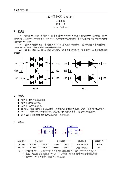
ESD5Zxx (1connection to GND for ESD5Zxx )
Page 3
3/9/2009 Rev2.3
Suppressors (TVS) are an ideal choice for ESD protection. They are capable of clamping the incoming transient to a low enough level such that damage to the protected semiconductor is prevented. Surface mount TVS offers the best choice for minimal lead inductance. They serve as parallel protection elements, connected between the signal line
ESD5Z5V-2/TR
Z*H
5
0.05
6.2
6.87.81Fra bibliotek11.6
18.6
9.4
174
50
ESD5Z7V-2/TR
Z*J
7
0.01
7.5
8.2
9.2
1
13.5
22.7
8.8
200
40
* Surge current waveform per Figure 1. Note1: VBR is measured with a pulse test current IT at an ambient temperature of 25°C.
Shipping 3000 Tape & Reel
ESD5Zxx-2/TR
SOD-523
Absolute Ratings (Tamb=25oC )
Symbol PPP TL Tstg Top Tj Parameter Peak Pulse Power (tp = 8/20μs) Maximum lead temperature for soldering during 10s Storage Temperature Range Operating Temperature Range Maximum junction temperature IEC61000-4-2 (ESD) Air discharge Contact discharge IEC61000-4-4 (EFT) ESD Voltage Per Human Body Model Per Machine Model Value 200 260 -55 to +155 -40 to +125 150 25 25 40 16 400 A KV V Units W
ESD5Zxx Series
ESD5Zxx Series
Transient Voltage Suppressors for ESD Protection General Description The ESD5Zxx Series is designed to protect voltage sensitive components from ESD and transient voltage events. Excellent clamping capability, low leakage, and fast response time, make these parts ideal for ESD protection on designs where board space is at a premium. Features Small Body Outline Dimensions Low Body Height Working Peak Reverse Voltage: 2.5 V- 7.0 V Peak Power up to 200 Watts @ 8 x 20 s Pulse Low Leakage Response Time is Typically < 1 ns ESD Rating of Class 3 (> 16 kV) per Human Body Model Applications Cellular phones Portable devices Digital cameras Power supplies
o o o o
C C C C
KV
Page 1
3/9/2009 Rev2.3
ESD5Zxx Series3
Electrical Parameter
Symbol IPP VC VRWM IR IT VBR IF VF Parameter Maximum Reverse Peak Pulse Current Clamping Voltage @ IPP Working Peak Reverse Voltage Maximum Reverse Leakage Current @ VRWM Test Current Breakdown Voltage @ IT
1 1 Cathode 2 Anode 1 SOD 523
2
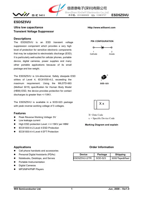
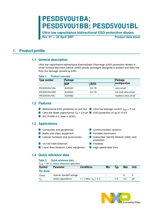
PIN CONFIGURATION
MARKING DIAGRAM
Zx 2
Z = Date Code x = Specific Device Code
Order Information
Part Number Package
Figure 1. 8 x 20 ms Pulse Waveform
Page 2
3/9/2009 Rev2.3
ESD5Zxx Series3
ESD5Z5V SERIES
Figure 2. Positive 8 kV contact per IEC 6100 4 2 ESD5Z5V-2/TR
Figure 3. Negative 8 kV contact per IEC 6100 4 2 ESD5Z5V-2/TR
Application Note
Electrostatic discharge (ESD) is a major cause of failure in electronic systems. Transient Voltage and ground. As the transient rises above the operating voltage of the device, the TVS becomes a low impedance path diverting the transient current to ground. The ESD5Zxx is the ideal board level protection of ESD sensitive semiconductor components. The tiny SOD-523 package allows design flexibility in the design of high density boards where the space saving is at a premium. This enables to shorten the routing and contributes to hardening against ESD.
100 % OF PEAK PULSE CURRENT 90 80 70 60 50 40 30 20 10 0 0 20 40 t, TIME (ms) 60 80 tP
tr
PEAK VALUE IRSM @ 8 ms PULSE WIDTH (tP) IS DEFINED AS THAT POINT WHERE THE PEAK CURRENT DECAY = 8 ms HALF VALUE IRSM/2 @ 20 ms
Min 0.043 0.028 0.020 0.010 0.0028 0.006 0.059
Nom 0.047 0.032 0.024 0.012 0.0055 0.008 0.063
Max 0.051 0.035 0.028 0.014 0.0079 0.010 0.067
Min A B C D J K S
ESD5Zxx Series3
Package mechanical data
Dim
Millimeters
Inches
Min A B C D J K S 1.10 0.70 0.50 0.25 0.07 0.15 1.50
Nom 1.20 0.80 0.60 0.30 0.14 0.20 1.60
Max 1.30 0.90 0.70 0.35 0.20 0.25 1.70
V
Forward Current Forward Voltage @ IF Uni Directional TVS
Electrical Characteristics Ratings at 25 °C ambient temperature unless otherwise specified. VF = 0.9V at IF = 10mA
Device Device Marking VRWM (V) IR(uA) @ VRWM VBR (V) @ IT (Note 1) VBR (V) @ IT VBR (V) @ IT IT (mA) VC (V) @IPP=5A* VC (V) @Max IPP* IPP (A)* PPK (W)* C (pF)
Nom 1.10 0.70 0.50 0.25 0.07 0.15 1.50
Page 4
3/9/2009 Rev2.3
Figure4: ESD5Zxx protection against ESD
I/ O LINES
ESD sensitive device
GND
ESD5Zxx (1connection to GND for ESD5Zxx )
Page 3
3/9/2009 Rev2.3
Suppressors (TVS) are an ideal choice for ESD protection. They are capable of clamping the incoming transient to a low enough level such that damage to the protected semiconductor is prevented. Surface mount TVS offers the best choice for minimal lead inductance. They serve as parallel protection elements, connected between the signal line
ESD5Z5V-2/TR
Z*H
5
0.05
6.2
6.87.81Fra bibliotek11.6
18.6
9.4
174
50
ESD5Z7V-2/TR
Z*J
7
0.01
7.5
8.2
9.2
1
13.5
22.7
8.8
200
40
* Surge current waveform per Figure 1. Note1: VBR is measured with a pulse test current IT at an ambient temperature of 25°C.
Shipping 3000 Tape & Reel
ESD5Zxx-2/TR
SOD-523
Absolute Ratings (Tamb=25oC )
Symbol PPP TL Tstg Top Tj Parameter Peak Pulse Power (tp = 8/20μs) Maximum lead temperature for soldering during 10s Storage Temperature Range Operating Temperature Range Maximum junction temperature IEC61000-4-2 (ESD) Air discharge Contact discharge IEC61000-4-4 (EFT) ESD Voltage Per Human Body Model Per Machine Model Value 200 260 -55 to +155 -40 to +125 150 25 25 40 16 400 A KV V Units W
ESD5Zxx Series
ESD5Zxx Series
Transient Voltage Suppressors for ESD Protection General Description The ESD5Zxx Series is designed to protect voltage sensitive components from ESD and transient voltage events. Excellent clamping capability, low leakage, and fast response time, make these parts ideal for ESD protection on designs where board space is at a premium. Features Small Body Outline Dimensions Low Body Height Working Peak Reverse Voltage: 2.5 V- 7.0 V Peak Power up to 200 Watts @ 8 x 20 s Pulse Low Leakage Response Time is Typically < 1 ns ESD Rating of Class 3 (> 16 kV) per Human Body Model Applications Cellular phones Portable devices Digital cameras Power supplies
o o o o
C C C C
KV
Page 1
3/9/2009 Rev2.3
ESD5Zxx Series3
Electrical Parameter
Symbol IPP VC VRWM IR IT VBR IF VF Parameter Maximum Reverse Peak Pulse Current Clamping Voltage @ IPP Working Peak Reverse Voltage Maximum Reverse Leakage Current @ VRWM Test Current Breakdown Voltage @ IT
1 1 Cathode 2 Anode 1 SOD 523
2
PIN CONFIGURATION
MARKING DIAGRAM
Zx 2
Z = Date Code x = Specific Device Code
Order Information
Part Number Package
Figure 1. 8 x 20 ms Pulse Waveform
Page 2
3/9/2009 Rev2.3
ESD5Zxx Series3
ESD5Z5V SERIES
Figure 2. Positive 8 kV contact per IEC 6100 4 2 ESD5Z5V-2/TR
Figure 3. Negative 8 kV contact per IEC 6100 4 2 ESD5Z5V-2/TR
Application Note
Electrostatic discharge (ESD) is a major cause of failure in electronic systems. Transient Voltage and ground. As the transient rises above the operating voltage of the device, the TVS becomes a low impedance path diverting the transient current to ground. The ESD5Zxx is the ideal board level protection of ESD sensitive semiconductor components. The tiny SOD-523 package allows design flexibility in the design of high density boards where the space saving is at a premium. This enables to shorten the routing and contributes to hardening against ESD.
100 % OF PEAK PULSE CURRENT 90 80 70 60 50 40 30 20 10 0 0 20 40 t, TIME (ms) 60 80 tP
tr
PEAK VALUE IRSM @ 8 ms PULSE WIDTH (tP) IS DEFINED AS THAT POINT WHERE THE PEAK CURRENT DECAY = 8 ms HALF VALUE IRSM/2 @ 20 ms
Min 0.043 0.028 0.020 0.010 0.0028 0.006 0.059
Nom 0.047 0.032 0.024 0.012 0.0055 0.008 0.063
Max 0.051 0.035 0.028 0.014 0.0079 0.010 0.067
Min A B C D J K S
ESD5Zxx Series3
Package mechanical data
Dim
Millimeters
Inches
Min A B C D J K S 1.10 0.70 0.50 0.25 0.07 0.15 1.50
Nom 1.20 0.80 0.60 0.30 0.14 0.20 1.60
Max 1.30 0.90 0.70 0.35 0.20 0.25 1.70