施耐德智能马达控制器培训
- 格式:ppt
- 大小:8.37 MB
- 文档页数:147
施耐德培训M340培训教程1.引言施耐德电气作为全球能源管理和自动化领域的领导者,一直致力于为客户提供高效、可靠和安全的解决方案。
M340作为施耐德电气的一款高性能可编程逻辑控制器(PLC),具有强大的数据处理能力、灵活的编程环境和广泛的应用领域。
为了帮助用户更好地掌握M340的使用方法和编程技巧,本教程将详细介绍M340的基本概念、硬件组成、软件安装与配置、编程方法以及应用案例。
2.M340基本概念2.1PLC概述PLC(可编程逻辑控制器)是一种广泛应用于工业自动化领域的通用控制器。
它通过编程实现对输入信号的逻辑处理,输出信号控制执行器完成各种任务。
PLC具有结构紧凑、编程灵活、抗干扰能力强、可靠性高等特点。
2.2M340特点1)强大的数据处理能力:M340采用高性能处理器,具备强大的数据处理能力,满足复杂控制需求。
2)灵活的编程环境:支持多种编程语言,如LD(梯形图)、IL (指令列表)、FBD(功能块图)等,满足不同用户的需求。
3)广泛的应用领域:M340适用于各种工业自动化领域,如生产线控制、机床控制、过程控制等。
4)高可靠性:采用模块化设计,具备良好的抗干扰能力和散热性能,保证系统稳定运行。
3.M340硬件组成3.1处理器模块处理器模块是M340的核心部件,负责执行用户程序、处理输入输出信号和与其他设备通信。
根据性能和功能需求,M340处理器模块分为多个系列,如BMX、CMX、EMX等。
3.2输入输出模块输入输出模块用于连接外部设备,如传感器、执行器等。
M340提供丰富的输入输出模块,包括数字量、模拟量、热电阻、热电偶等类型。
3.3通信模块通信模块用于实现M340与其他设备或系统之间的数据交换。
M340支持多种通信协议,如以太网、CANopen、Modbus等。
4.M340软件安装与配置4.1软件安装M340编程软件为SoMachine,用户需从施耐德电气官网相应版本并进行安装。
安装过程中,需确保计算机满足软件运行要求。

施耐德M340PLC培训教材•PLC基础知识•施耐德M340PLC硬件系统•施耐德M340PLC软件系统•基本指令与功能实现目录•高级功能应用与扩展•故障诊断与维护保养策略01PLC基础知识PLC定义与发展历程PLC定义可编程逻辑控制器(Programmable Logic Controller,PLC)是一种数字运算操作的电子系统,专为在工业环境下应用而设计。
发展历程从1969年美国DEC公司研制出第一台PLC开始,经过几十年的发展,PLC已经由最初的逻辑控制扩展到运动控制、过程控制等领域,成为工业自动化领域的重要组成部分。
PLC工作原理及结构组成工作原理PLC采用循环扫描的工作方式,通过输入接口采集现场信号,经过内部处理后再通过输出接口控制现场设备。
结构组成主要包括CPU、存储器、输入输出接口、电源等部分。
其中,CPU是PLC的核心部件,负责执行用户程序;存储器用于存储用户程序和数据;输入输出接口用于连接现场设备和PLC内部电路;电源为PLC提供工作电压。
PLC编程语言与标准编程语言PLC的编程语言主要有梯形图(LD)、指令表(IL)、功能块图(FBD)、顺序功能图(SFC)和结构化文本(ST)五种。
其中,梯形图是最常用的编程语言,具有直观易懂的优点。
标准国际电工委员会(IEC)制定了PLC的编程语言和通信标准,即IEC 61131-3标准。
该标准规定了PLC编程语言的语法、语义和显示方式,以及PLC之间通信的协议和规范,为不同厂商生产的PLC 提供了统一的编程和通信接口。
02施耐德M340PLC硬件系统CPU 模块内存模块通信模块提供大容量存储空间,支持程序和数据的高效存储。
支持多种通信协议,实现与其他设备的可靠通信。
0302 01采用高性能处理器,实现快速逻辑运算和数据处理。
可根据需求添加扩展模块,实现更多功能。
体积小巧,节省安装空间。
采用工业级元器件,确保长时间稳定运行。
支持在线诊断和远程维护,降低维护成本。
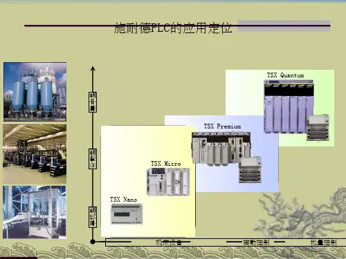

施耐德Quantum系列自动化培训教程施耐德Quantum系列自动化培训教程是施耐德电气推出的一套针对Quantum自动化控制系统的培训教程。
该教程从基础入手,重点介绍了Quantum控制系统的硬件结构、软件编程、项目实施和维护等方面的知识,是Quantum系统初学者和从业人员的必备学习资料。
一、Quantum控制系统简介Quantum控制系统是施耐德电气公司生产的一种高端自动化控制系统。
它具有高可靠性、高扩展性和高性能等特点,广泛应用于机械制造、能源管理、化工、公用事业等领域。
Quantum控制系统由CPU、IO模块、通讯模块、电源等组成,集成了多种通讯协议和编程语言,可以实现多种复杂的控制任务。
二、施耐德Quantum系列自动化培训教程概述施耐德Quantum系列自动化培训教程是一套针对Quantum自动化控制系统的全面培训教程。
它以实例为主线,通过生动的演示和详尽的讲解,使学员能够深入理解Quantum 控制系统的组成结构和运行原理,掌握系统的编程技巧和应用实践经验,提高系统的开发和维护能力。
三、施耐德Quantum系列自动化培训教程的内容1、Quantum控制系统概述:介绍了Quantum控制系统的硬件组成、软件结构、通讯协议和编程语言,为学员打下了系统的基础知识。
2、软件界面和操作流程:详细说明了Quantum的软件界面和各个功能模块的操作流程,不仅有助于学员快速掌握软件操作技巧,还可以提高系统的开发效率。
3、软件编程基础:重点讲解了Quantum的编程语言FBD、LD和ST的语法结构和应用技巧,使学员能够熟练掌握编程技能,灵活应用到实际项目中。
4、系统实现案例:通过几个实际项目的案例,介绍了Quantum控制系统在不同领域的应用实践,帮助学生了解系统在实际工程中的应用。
5、系统维护与故障排除:详细说明了Quantum控制系统的维护和故障排除方法,为系统从业人员提供了有力的技术支持。
四、施耐德Quantum系列自动化培训教程的特点1、专业性强:教程内容深入浅出,围绕Quantum控制系统的硬件、软件和应用展开,有助于学员深入理解系统的结构和运行原理。
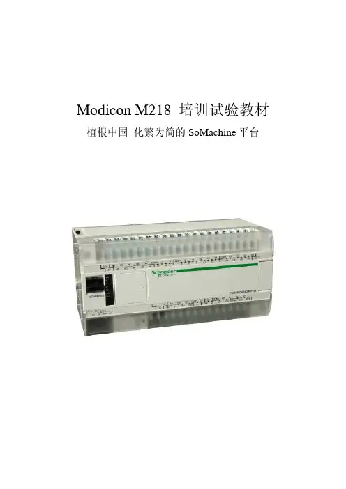
Modicon M218 培训试验教材植根中国化繁为简的SoMachine平台目录M218基础培训示例教材 (3)M218高速计数器示例 (3)PTO使用示例 (17)PWM示例 (47)串口Modbus通讯示例 (52)自由协议通讯 (62)以太网通讯示例 (69)PID示例 (77)RTC实现示例 (84)M218基础培训试验教材 (103)试验一-SoMachine软件入门 (103)试验二-开关量和模拟量试验 (113)试验三-PTO试验 (118)试验四-串口通信试验 (128)试验五-以太网通信试验 (134)M218基础培训示例教材M218高速计数器示例内容简介:本文介绍如何通过M218的高速计数器功能实现冷弯成型机的定长裁剪控制。
1.冷弯成型机控制系统描述:冷弯成型机最基本的控制要求是将滚压成型完成的材料送到指定位置,然后进行压膜或者裁切动作。
材料的输送电机由变频器控制。
在靠近压膜或者裁剪机构的滚轮上安装有用于计长的旋转编码器,PLC实时检测该编码器的脉冲信号并换算成长度数值。
当机器启动时,PLC将实际检测的长度数值与设定数值进行比较,控制变频器进行多段速定位。
即当长度到达阀值0时,变频器切换到低速;当长度到达阀值1时变频器输出0速。
(图1) 冷弯机控制系统说明裁剪机构上检测开关的上升沿可以用于捕捉,当裁剪机构动作时的编码器值,通过该值自动修正阀值1的设定值;同时,该检测开关的下降沿用于将编码器的当前值复位成预设值,重新计数。
变频器多段速设置,当阀值0和阀值1的反馈输出都为FALSE的时候,变频器以高速运行,频率50Hz;当阀值0输出TRUE时,频率切换到第二段速低速5Hz;当阀值1输出TRUE时,频率切换到第三段速0Hz。
2.编码器选型:安装编码器的滚轮周长是250mm,冷弯机的设计速度是15米/分钟,即滚轮的最大速度是1转/秒。
设计采用的编码器脉冲输入是2000脉冲/转,即脉冲输入信号最大为2KHz,小于M218高速计数器的最大采样输入100KHz。
OverviewBulletin 150 — Smart Motor Controllers — SMC-2™The SMC-2™ Controller is a compact, multi-functional, versatile solid-state controller used in starting standard three-phase squirrel-cage induction motors. Three standard modes of operation are available within a single controller:Standards Compliance/Approvalsy CE Marked (Open Type) Per Low Voltage Directive 73/23/EEC, 93/68/EEC y CSA Certified (Open Type) (File No. LR1234)y UL Listed (Open Type) (File No. E96956, Guide No. NMFT)Your order must include 1) cat. no. of the controller selected, 2) if required, suffix code and description of any modifications, and 3) if required, cat. no. of any options or accessories.Series ControllerThe SMC-2 Controller is designed to operate in series with an electromechanical motor starter. The series mode has the following features:y Eliminates the need for additional control wiring, simplifying initial installation.y Works in unison with an existing electromechanical motor starter for easy retrofits.y Allows easy set-up with digital adjustments eliminating the guesswork of setting analog potentiometers.Controller with Interface Optiony Soft Starty Current Limit Start y Full Voltage Starty Optional Soft Stop (Requires Interface Module)The SMC-2™ Controller is available in eight sizes: 5, 9, 16, 24, 35, 54,68, and 97 A. It is offered in three voltage ranges: 200…230V ,380…460V , and 500…575V , 50/60 Hz.The SMC-2™ Controller can be used in two configurations: as a series controller and as a motor controller with an interface option.Table of ContentsCat. No. Explanation 6-37Product Selection . . .6-38Accessories . . . . . . . . .6-41Options . . . . . . . . . . . . .6-41Specifications . . . . . . .6-42ApproximateDimensions . . . . . . . . .6-43Enclosed Options . . .6-68The SMC-2 Controller with the interface option is designed so it can be operated without an electromechanical motor starter. The SMC-2Controller with the interface option offers the following features:y Provides ON/OFF control directly to the controller through an external pilot device. In many applications the interface option may eliminate the need for an additional contactor if electrical isolation or soft stop is not required. This reduces panel space requirements.y Provides a selectable auxiliary contact, which operates as either an instantaneous or up-to-speed contact, making it available for a wide variety of control schemes.y Provides a Soft Stop feature that extends stopping time to minimize load shifting or spillage during stopping.The interface option can be field or factory installed. For devices rated 5…16 A, this is a plug-in module. For devices rated 24…97A, there is a PC board that replaces the existing board.Energy SaverThis built-in feature of the SMC-2 Controller is used to save energy on applications where the motor is lightly loaded or unloaded for long periods of time.Protective ModuleIn applications where the SMC-2 Controller is exposed to high or abnormal line transients, an optional protective module is available and can be mounted on both the line and load side of the unit. The protective module contains MOVs (Metal Oxide Varistors) that protect the SCR from line surges and snubber networks to shunt noise energy away.Cat. No. ExplanationCombinationbController RatingsCode Amps Max Hp Max kW 200230460575220380415500W0551133 1.1 2.2 2.23W0992257-1/2 2.244 5.5W161635101047.57.57.5W242457-1/21520 5.5111115W3535101025301018.52222W54541520405015223037W68682025506018.5333745W97973030757525455563Open and Non-CombinationaBulletin NumberCode Description150Solid-State ControllerbController Ratings Code Amps Max Hp Max kW200230460575220380415500A0551133 1.1 2.2 2.23A0992257-1/2 2.244 5.5A161635101047.57.57.5A242457-1/21520 5.5111115A3535101025301018.52222A54541520405015223037A68682025506018.5333745A97973030757525455563cEnclosure TypeCode Description N OpenF NEMA Type 4 (IP65)JNEMA Type 12dInput Line VoltageCode DescriptionA 200…230V AC (+10%,–15%), 50 and 60 Hz,3-phaseB 380…460V AC (+10%,–15%), 50 and 60 Hz,3-phaseC 500…575+10%, –15%), 50and 60 Hz,3-phaseaBulletin NumberCode Description152CCombination Solid-State Reduced Voltage Controller with Fusible Disconnect and Isolation Contactor 152XCombination Solid-State Reduced Voltage Controller with FusibleDisconnect, 120V Interface Module and Control Circuit Transformer, withoutIsolation ContactorcEnclosure TypeCode Description F NEMA Type 4 (IP65)JNEMA Type 12 (IP64)150–A05NB –D1–8L4–NA –7a bcde f g h152C –W05JBD –D1–ND –8L4abcdefg1IEC overload relays are rated for Class 10 operation.†Overload option for 5…16 A only (open type) and non-combination or combination unit (5…97 A units).‡Protective modules factory installed on 5…54 A units only. 68 and 97 A are field modifications only.§When an IEC overload relay is selected, protective modules are limited to line side only. (For 5…16 A rated controllers only.)♣Interface option provides selectable auxiliary contact and Soft Stop feature.®External overload reset available for 5…97 A rated controllers ordered as a non-combination or combination unit with an overload relay.a IEC overload relays are rated for Class 10 operation for 5…97 A rated controllers only. See Table “e”for IEC overload selection. For 24…97 A rated controllers, NEMA overloads are furnished as standard. Requires control power source.eOverload Relay Selection 1†Code Current Rating C10.32...1.0D1 1.0...2.9E1 1.6...5.0F1 3.7...12H112...32H212...38J214...45K323...75L466 (110)fProtective Modules ‡Line SideBoth Line andLoad230V AC 8L2230V AC 8B2§460V AC 8L4460V AC 8B4§575V AC 8L6575V AC 8B6§gInterface Option ♣Code NANDControl Voltage200…240V (+10%, –15%),50 and 60 Hz, single-phase 100…120V (+10%, –15%),50 and 60 Hz, single-phasehExternal Reset ®Code 7DescriptionFor NEMA Type 4 (IP65) or NEMA Type 12 (IP64)For a listing of availableoptions, please see page 6-68dInput Line VoltageAC LineVoltage 200208230400460500575Hz50606050605060Common H H A I B M C Control Wiring Method Separate Control120V/60Hz Secondary —HD AD —BD —CD 110V/50Hz SecondaryHS ——NS —MS —eOverload Selection aCodeCurrent RatingSee table “e” above for detailsfInterface Option ♣CodeNANDControl Voltage 200…230V (+10%, –15%), 50 and 60 Hz,single-phase100…120V (+10%, –15%), 50 and 60 Hz,single-phasegProtective Modules ‡§Line Side230V AC460V AC8L28L4Both Line and Load 230V AC 460V AC 8B28B4Product SelectionOpen Type and Non-Combination ControllersNon-combination is the SMC-2 Controller in an IP65 (Type 4) or IP54 (Type 12) enclosure. It is available with the same options as the Open Type and is also available with an external reset for overloads. See Accessories and Options on page 6-41. For a listing of all available options, please see page 6-68.Accessories — Page 6-41Options — Page 6-41Open type is a stand-alone SMC-2 Controller. Options which can be added to open type 5…16 A controllers are an interface module, solid-state type overload relay, and protective module(s).Rated OperationalCurrentkW Hp Open Type Dimension Code 1IP65 — NEMA Type 4 EnclosureIP54 — NEMA Type 12 EnclosureCat. No.†Cat. No.†Cat. No.†200V AC, 50/60 Hz5 A 1/3…1150-A05NA S 150-A05FA 150-A05JA 9 A 1/3…2150-A09NA S 150-A09FA 150-A09JA 16 A 1/3…3150-A16NA T 150-A16FA 150-A16JA 24 A 1…5150-A24NA U 150-A24FA 150-A24JA 35 A 1…10150-A35NA U 150-A35FA 150-A35JA 54 A 1…15150-A54NA U 150-A54FA 150-A54JA 68 A 1…20150-A68NA V 150-A68FA 150-A68JA 97 A1 (30)150-A97NA V150-A97FA ‡150-A97JA ‡230V AC, 50/60 Hz5 A 1.11/3…1150-A05NA S 150-A05FA 150-A05JA 9 A 2.21/3…2150-A09NA S 150-A09FA 150-A09JA 16 A 41/3…5150-A16NA T 150-A16FA 150-A16JA 24 A 5.51…7-1/2150-A24NA U 150-A24FA 150-A24JA 35 A 7.51…10150-A35NA U 150-A35FA 150-A35JA 54 A 151…20150-A54NA U 150-A54FA 150-A54JA 68 A 18.51…25150-A68NA V 150-A68FA 150-A68JA 97 A 251…30150-A97NAV 150-A97FA ‡150-A97JA ‡400…460V AC, 50/60 Hz 5 A 2.21/3…3150-A05NB S 150-A05FB 150-A05JB 9 A 41/3…5150-A09NB S 150-A09FB 150-A09JB 16 A 7.51/3…10150-A16NB T 150-A16FB 150-A16JB 24 A 111…15150-A24NB U 150-A24FB 150-A24JB 35 A 221…25150-A35NB U 150-A35FB 150-A35JB 54 A 301…40150-A54NB U 150-A54FB 150-A54JB 68 A 371…50150-A68NB V 150-A68FB 150-A68JB 97 A 551…75150-A97NBV 150-A97FB ‡150-A97JB ‡500…575V AC, 50/60 Hz5 A 31/3…3150-A05NC S 150-A05FC 150-A05JC 9 A 5.51/3…7-1/2150-A09NC S 150-A09FC 150-A09JC 16 A 7.51/3…10150-A16NC T 150-A16FC 150-A16JC 24 A 151…20150-A24NC U 150-A24FC 150-A24JC 35 A 221…30150-A35NC U 150-A35FC 150-A35JC 54 A 301…50150-A54NC U 150-A54FC 150-A54JC 68 A 451…60150-A68NC V 150-A68FC 150-A68JC 97 A631 (75)150-A97NCV150-A97FC ‡150-A97JC ‡1Optional accessories may increase panel dimensions.†For factory-installed options, add the appropriate suffix from page 6-41.‡97 A (Type 4 and Type 12) controllers include bypass contactors.Product Selection, Continued24…97 A controllers. A combination controller without the isolation contactor consists of a rod operated fusible disconnect, the SMC-2Controller with an interface option, a control circuit transformer, and a 3-pole thermal overload relay. Again, for 5…97 A controllers, the current range must be selected for a solid-state overload or a eutectic alloy type overload will be provided (less elements).For a listing of all available options, please see page 6-68.Combination controllers can be ordered with or without the isolation contactor. A combination controller with the isolation contactorconsists of a rod-operated fusible disconnect, the SMC-2 Controller,and a 3-pole thermal overload relay. For 5…97 A controllers, the current range of the solid-state overload relay must be selected from the chart on page 6-41. Otherwise, a eutectic alloy typeoverload relay (less elements) will be provided in place of the solid-state overload. Eutectic alloy overloads are standard on enclosedRated Opera-tionalCurrent kW Hp Dim.CodeWith Isolation ContactorWithout IsolationContactorCat. No.Cat. No.200V AC, 60 Hz 5 A 1/3…1S 152C-W05FH ♣152X-W05FH-ND-6P 9 A 1/3…2T 152C-W09FH ♣152X-W09FH-ND-6P 16 A 1/3…3T 152C-W16FH ♣152X-W16FH-ND-6P 24 A 1…5U 152C-W24FH ♣152X-W24FH-ND-6P 35 A 1…10U 152C-W35FH ♣152X-W35FH-ND-6P 54 A 1…15V 152C-W54FH ♣152X-W54FH-ND-6P 68 A 1…20V 152C-W68FH ♣152X-W68FH-ND-6P97 A1 (30)V 152C-W97FH ♣®152X-W97FH-ND-6P ®230V AC, 60 Hz5 A 1/3…1S 152C-W05FA ♣152X-W05FA-ND-6P 9 A 1/3…2T 152C-W09FA ♣152X-W09FA-ND-6P 16 A 1/3…5T 152C-W16FA ♣152X-W16FA-ND-6P 24 A 1…7-1/2U 152C-W24FA ♣152X-W24FA-ND-6P 35 A 1…10U 152C-W35FA ♣152X-W35FA-ND-6P 54 A 1…20V 152C-W54FA ♣152X-W54FA-ND-6P 68 A 1…25V 152C-W68FA ♣152X-W68FA-ND-6P97 A1 (30)V 152C-W97FA ♣®152X-W97FA-ND-6P ®460V AC, 60 Hz5 A 1/3…3S 152C-W05FB ♣152X-W05FB-ND-6P 9 A 1/3…5T 152C-W09FB ♣152X-W09FB-ND-6P 16 A 1/3…10T 152C-W16FB ♣152X-W16FB-ND-6P 24 A 1…15U 152C-W24FB ♣152X-W24FB-ND-6P 35 A 1…25U 152C-W35FB ♣152X-W35FB-ND-6P 54 A 1…40V 152C-W54FB ♣152X-W54FB-ND-6P 68 A 1…50V 152C-W68FB ♣152X-W68FB-ND-6P97 A 1…75V 152C-W97FB ♣®152X-W97FB-ND-6P ®575V AC, 60 Hz5 A 1/3…3S 152C-W05FC ♣152X-W05FC-ND-6P 9 A 1/3…7-1/2T 152C-W09FC ♣152X-W09FC-ND-6P 16 A 1/3…10T 152C-W16FC ♣152X-W16FC-ND-6P 24 A 1…20U 152C-W24FC ♣152X-W24FC-ND-6P 35 A 1…30U 152C-W35FC ♣152X-W35FC-ND-6P 54 A 1…50V 152C-W54FC ♣152X-W54FC-ND-6P 68 A 1…60V 152C-W68FC ♣152X-W68FC-ND-6P97 A1 (75)V152C-W97FC ♣®152X-W97FC-ND-6P ®Rated Opera-tionalCurrent kW Hp DimensionCodeWith Isolation ContactorWithout IsolationContactorCat. No.Cat. No.220V AC, 50 Hz5 A 1.1 S 152C-W05FA ♣152X-W05FA-ND-6P 9 A 2.2 T 152C-W09FA ♣152X-W09FA-ND-6P 16 A 4 T 152C-W16FA ♣152X-W16FA-ND-6P 24 A 5.5 U 152C-W24FA ♣152X-W24FA-ND-6P 35 A 7.5 U 152C-W35FA ♣152X-W35FA-ND-6P 54 A 15 V 152C-W54FA ♣152X-W54FA-ND-6P 68 A 18.5 V 152C-W68FA ♣152X-W68FA-ND-6P97 A 25 V 152C-W97FA ♣®152X-W97FA-ND-6P ®400V AC, 50 Hz5 A 2.2 S 152C-W05FI ♣152X-W05FI-ND-6P 9 A 4 T 152C-W09FI ♣152X-W09FI-ND-6P 16 A 7.5 T 152C-W16FI ♣152X-W16FI-ND-6P 24 A 11 U 152C-W24FI ♣152X-W24FI-ND-6P 35 A 22 U 152C-W35FI ♣152X-W35FI-ND-6P 54 A 30 V 152C-W54FI ♣152X-W54FI-ND-6P 68 A 37 V 152C-W68FI ♣152X-W68FI-ND-6P 97 A 55 V 152C-W97FI ♣®152X-W97FI-ND-6P ®500V AC, 50 Hz5 A 3 S 152C-W05FM ♣152X-W05FM-ND-6P 9 A 5.5 T 152C-W09FM ♣152X-W09FM-ND-6P 16 A 7.5 T 152C-W16FM ♣152X-W16FM-ND-6P 24 A 15 U 152C-W24FM 152X-W24FM-ND-6P 35 A 22 U 152C-W35FM ♣152X-W35FM-ND-6P 54 A 30 V 152C-W54FM ♣152X-W54FM-ND-6P 68 A 45 V 152C-W68FM ♣152X-W68FM-ND-6P97 A63V152C-W97FM ♣®152X-W97FM-ND-6P ®IP65 (Type 4) Combination Controllers†‡§†For 5…97 A controllers, a solid-state overload current range must be selected from the chart on page 6-41 and the suffix added to the cat. no. Otherwise, a eutectic alloy overload will be provided.‡Refer to page 6-42 for fuse clip sizing and type information.§Fuses are not included.♣For 120V , 60 Hz separate control, add the letter “D” after the 9th character. For 110V , 50 Hz separate control, add the letter “S” after the 9th character.Example: Cat. No. 152C-W05FH becomes Cat. No. 152C-W05FHD for 120V , 60 Hz separate control.®97 A Type 4 SMC-2 Smart Motor Controllers include Bulletin 100 bypass contactors wired for 120V AC 50/60 Hz control.Accessories — Page 6-41Options — Page 6-41Product Selection, ContinuedAccessories — Page 6-4124…97 A controllers. A combination controller without the isolation contactor consists of a rod-operated fusible disconnect, the SMC-2 Controller with an interface option, a control circuit transformer, and a 3-pole thermal overload relay. Again, for 5…97 A controllers, the current range must be selected for a solid-state overload or a eutectic alloy type overload will be provided (less elements).For a listing of all available options, please see page 6-68.Combination controllers can be ordered with or without the isolation contactor. A combination controller with the isolation contactor consists of a rod operated fusible disconnect, the SMC-2 Controller, and a 3-pole thermal overload relay. For 5…97 A controllers, the current range of the solid-state overload relay must be selected from the chart on page 6-41. Otherwise, a eutectic alloy type overload relay (less elements) will be provided in place of the solid-state overload. Eutectic alloy overloads are standard on enclosed CurrentRating(A)kW Hp DimensionCodeWith IsolationContactorWithout IsolationContactorCat. No.Cat. No.220V AC, 50 Hz5 A 1.1 S152C-W05JA♣152X-W05JA-ND-6P 9 A 2.2 T152C-W09JA♣152X-W09JA-ND-6P 16 A4 T152C-W16JA♣152X-W16JA-ND-6P 24 A 5.5 U152C-W24JA♣152X-W24JA-ND-6P 35 A7.5 U152C-W35JA♣152X-W35JA-ND-6P 54 A15 V152C-W54JA♣152X-W54JA-ND-6P 68 A18.5 V152C-W68JA♣152X-W68JA-ND-6P 97 A25 V152C-W97JA♣®152X-W97JA-ND-6P♣®400V AC, 50 Hz5 A 2.2 S152C-W05JI♣152X-W05JI-ND-6P 9 A4 T152C-W09JI♣152X-W09JI-ND-6P 16 A7.5 T152C-W16JI♣152X-W16JI-ND-6P 24 A11 U152C-W24JI♣152X-W24JI-ND-6P 35 A22 U152C-W35JI♣152X-W35JI-ND-6P 54 A30 V152C-W54JI♣152X-W54JI-ND-6P 68 A37 V152C-W68JI♣152X-W68JI-ND-6P 97 A55 V152C-W97JI♣®152X-W97JI-ND-6P®500V AC, 50 Hz5 A3 S152C-W05JM♣152X-W05JM-ND-6P 9 A 5.5 T152C-W09JM♣152X-W09JM-ND-6P 16 A7.5 T152C-W16JM♣152X-W16JM-ND-6P 24 A15 U152C-W24JM♣152X-W24JM-ND-6P 35 A22 U152C-W35JM♣152X-W35JM-ND-6P 54 A30 V152C-W54JM♣152X-W54JM-ND-6P 68 A45 V152C-W68JM♣152X-W68JM-ND-6P 97 A63 V152C-W97JM♣®152X-W97JM-ND-6P®CurrentRating(A)kW HpDim.CodeWith IsolationContactorWithout IsolationContactorCat. No.Cat. No.200V AC, 60 Hz5 A 1/3…1S152C-W05JH♣152X-W05JH-ND-6P 9 A 1/3…2T152C-W09JH♣152X-W09JH-ND-6P 16 A 1/3…3T152C-W16JH♣152X-W16JH-ND-6P 24 A 1…5U152C-W24JH♣152X-W24JH-ND-6P 35 A 1…10U152C-W35JH♣152X-W35JH-ND-6P 54 A 1…15V152C-W54JH♣152X-W54JH-ND-6P 68 A 1…20V152C-W68JH♣152X-W68JH-ND-6P 97 A 1…30V152C-W97JH♣®152X-W97JH-ND-6P®230V AC, 60 Hz5 A 1/3…1S152C-W05JA♣152X-W05JA-ND-6P 9 A 1/3…2T152C-W09JA♣152X-W09JA-ND-6P 16 A 1/3…5T152C-W16JA♣152X-W16JA-ND-6P 24 A 1…7-1/2U152C-W24JA♣152X-W24JA-ND-6P 35 A 1…10U152C-W35JA♣152X-W35JA-ND-6P 54 A 1…20V152C-W54JA♣152X-W54JA-ND-6P 68 A 1…25V152C-W68JA♣152X-W68JA-ND-6P 97 A 1…30V152C-W97JA♣®152X-W97JA-ND-6P®460V AC, 60 Hz5 A 1/3…3S152C-W05JB♣152X-W05JB-ND-6P 9 A 1/3…5T152C-W09JB♣152X-W09JB-ND-6P 16 A 1/3…10T152C-W16JB♣152X-W16JB-ND-6P 24 A 1…15U152C-W24JB♣152X-W24JB-ND-6P 35 A 1…25U152C-W35JB♣152X-W35JB-ND-6P 54 A 1…40V152C-W54JB♣152X-W54JB-ND-6P 68 A 1…50V152C-W68JB♣152X-W68JB-ND-6P 97 A 1…75V152C-W97JB♣®152X-W97JB-ND-6P®575V AC, 60 Hz5 A 1/3…3S152C-W05JC♣152X-W05JC-ND-6P 9 A 1/3…7-1/2T152C-W09JC♣152X-W09JC-ND-6P 16 A 1/3…10T152C-W16JC♣152X-W16JC-ND-6P 24 A 1…20U152C-W24JC♣152X-W24JC-ND-6P 35 A 1…30U152C-W35JC♣152X-W35JC-ND-6P 54 A 1…50V152C-W54JC♣152X-W54JC-ND-6P 68 A 1…60V152C-W68JC♣152X-W68JC-ND-6P 97 A 1…75V152C-W97JC♣®152X-W97JC-ND-6P®IP54 (Type 12) Combination Controllers†‡§†For 5…97 A controllers, a solid-state overload current range must be selected from the chart on page 6-41 and the suffix added to the cat. no. Otherwise, a eutectic alloy overload will be provided.‡Refer to page 6-42 for fuse clip sizing and type information.§Fuses are not included.♣For 120V, 60 Hz separate control, add the letter “D” after the 9th character. For 110V, 50 Hz separate control, add the letter “S” after the 9th character. Example: Cat. No. 152C-W05FH becomes Cat. No. 152C-W05FHD for 120V, 60 Hz separate control.®97 A Type 12 SMC-2 Smart Motor Controllers include Bulletin 100 bypass contactors wired for 120V AC 50/60 Hz control.Accessories/OptionsProduct Selection — Page 6-38Options — this pageThe interface option provides ON/OFF control through an external device, a selectable auxiliary contact, and the soft stop feature. The interface option for the 24…97 A controller is a Printed Circuit Board (PCB) that replaces the existing board.Solid-State overload relays are rated for Class 10 operation only. If an overload is selected for the SMC-2 Controller, the current range must be indicated and the suffix added to the cat. no. (for 5…16 A open type controller and 5…97 A non-combination and combination controllers).Accessories Protective ModuleThe Protective Module mounts on the line or load side of the SMC-2 Controller. When the solid-state overload is used on a 5…16 A device,the Protective Module will mount only on the line side.Current Rating (A)Suffix 0.32...1.0-C11.0...2.9-D11.6...5.0-E13.7...12-F112...32-H112...38-H214...45-J223...75-K366 (110)-L4‡Overload relay option for 5…16 A open type and non-combinationcontrollers 5…97 A. Overload provided as standard for combination units and at no additional cost.OverloadsSolid-State Overload Relay ‡NEMA Overload RelayThe eutectic alloy overload relay is not available on the 5…16 Anon-combination or open type SMC-2 Controllers. To add a eutectic alloy overload relay to a combination controller, consult your local Allen-Bradley distributor.External Overload Relay ResetAdd the suffix “-7” to any enclosed SMC-2 Controller (NEMA Type 4and 12 non-combination or combination controller) containing an overload relay.Interface Option for Soft Stop1and Auxiliary Contact AC Standard Control Voltage,50/60 HzSMC-2Current Rating(A)Field Modification Factory Modification Suffix No., Line or LoadSide 1Factory Modification Suffix No., Both Line andLoad SideCat. No.200 (240)5…16150-N82T -8L2-8B224 (54)150-N82P68 A 150-N82P697 A 150-N82P9380 (480)5 (16)150-N84T -8L4-8B4Protective Module for 5…16 A24 (54)150-N84P68 A 150-N84P697 A 150-N84P9500 (600)5…16150-N86T -8L6-8B624 (54)150-N86P68 A150-N86P6Protective Module for 24…97 A97 A150-N86P91One Protective Module is provided, which will mount on either the line side or the load side. If a solid-state overload relay is used, the Protective Modulemounts on the line side only.SMC-2CurrentRating (A)Control VoltageLine Voltage,Max.Cat. No.Factory Modification Suffix No.5 (16)120V (+10%,-15%)200 (600)150-ND-ND240V (+10%,-15%)200…600150-NA -NA24 (97)120V (+10%,-15%)240150-N2D †-ND480150-N4D †600150-N6D †240V (+10%,-15%)240150-N2A †-NAInterface Module for 5…16 A480150-N4A †600150-N6A †1When Soft Stop is used without an isolation contactor, and the overloadtrips, the SMC-2 Controller will Soft Stop, not coast-to-stop.†Field Kit consists of a new control board for unit.Specifications1Consult NEC Handbook for proper fuse sizing guidelines.†Optional fuse clip sizes and types are available upon request. Consult factory.Electrical RatingsCat. No.150-A05…150-A09…150-A16…150-A24…150-A35…150-A54…150-A68…150-A97…Rated Operating Current (A)59162435546897Maximum Heat Dissipation (Watts)32457080120170215285Cable SizePower Terminals1.5…6 mm 2 1.5…6 mm 2 1.5…6 mm 210 mm 210 mm 210 mm 225 mm 250 mm 2Interface Option Terminals #14…12AWG#14...12AWG #14 (12)AWG#8 AWG #8 AWG #4 AWG#2 AWG#1/0 AWGRated Operational Voltage (+10%, –15%)200…240, 380…480, 500…600V AC, 50/60 Hz, 3-phaseThermal CapacityIEC 34 (S1), NEMA MG1Interface Option Voltage (+10%, –15%)100/120V or 200/240V , 50/60 Hz, 1-phasePower Requirements 15 VA MaximumHeatsink Fan———————45 VAAuxiliary Contact RatingNEMA C300IEC AC-15Electrical Design Specifications/Test RequirementsRepetitive Peak Inverse Voltage Rating 1200V up to 240V Line, 1400V up to 480V Line, 1600V up to 600V LineSelectable Soft Start Times Current Limit TimesSelectable Across-the-Line Starting Soft Stop Times2, 5, 10, 20, 25, and 30 seconds15 and 30 seconds1/10 second5, 10, 15, 25, 35, 45, 55, 110 secondsNoise and RF Immunity Surge Transient Peak 3400V . Showering Arc 1500VDV/DT ProtectionRC Snubber NetworkTransient Protection (Optional)Metal Oxide Varistors: (80 joules)Mechanical Design Specifications/Test RequirementsVibration 2.5 G for 60 minutes Shock30 G for 11 mSecsConstruction Power PolesControlMetal PartsHigh temperature thermoplastic moldingsThermoplastic moldingsAnodized aluminum, plated brass, or copperTerminals Power TerminalsControl TerminalsPower Terminal Markings6.0 mm hole with clamping plateUNC 6-32 Screw with self-tilting clamp plateCENELEC EN50 012, NEMAFunctional Design SpecificationsStandard FeaturesSetupWiring AdjustmentsThe SMC-2 Controller without options is wired in series with a motor starter.The SMC-2 Controller is configured with DIP switches and a rotary digital switch.StartingThree Modes Protection Soft Start, Current Limit, Full Voltage in one unit.The controller has pre-start protection from phase loss and shorted SCRs. An LED is provided to indicate the status of the unit. The LED is ON when 3-phase power is applied. A flashing LED indicates one of three conditions: shortedSCR or phase loss during start, or a stalled motor during run.RunningProtection Energy Level Stall protection available during starting and run condition for additional motor protection.Built-in energy saver available for low load conditions.Optional Interface FeaturesSetup Wiring2- and 3-wire control for wider variety of applications. Interface option requires no additional space and can befactory or field installed.Starting Auxiliary Selectable auxiliary contact available for either up-to-speed or instantaneous operation.Stopping Module allows for soft stopping to minimize load shifting. Also adjusted from standard DIP switches.EnvironmentalTemperature Operating Storage0…+50 °C (+32…+122 °F)–40…+85 °C (–40…+185 °F)Altitude 2000 m (6560 ft)Humidity5…95% Relative Humidity (non-condensing)Fuse Clip Sizing and Type for Fusible Combination Controllers 1†Horsepower @ 480VFuse Clip Size/TypeFuse Size Range1530 A/Class J 0...302060 A/Class J 31...602560 A/Class J 31...603060 A/Class J 31...6040100 A/Class J 61...10050100 A/Class J 61...10060200 A/Class J 101 (20075)200 A/Class J 101 (200)Approximate Dimensions Open TypeDimensions are shown in millimeters (inches). Dimensions are not intended to be used for manufacturing purposes.Controller5 A9 A16 AAWidth122 (4-13/16)122 (4-13/16)154 (6-5/64)BHeight127 (5)180 (7-3/32)180 (7-3/32)CDepth134 (5-9/32)134 (5-9/32)160 (6-5/16)D24 (61/64)24 (61/64)50 (1-31/32)E110 (4-11/32)110 (4-11/32)140 (5-33/64)F90 (3-35/64)140 (5-33/64)140 (5-33/64)Approx.Ship. Wt.2 kg (4.5 lbs)2.25 kg (5 lbs)3.15 kg (7 lbs)Controller 24…35 A 54 A…68 AAWidth214 (8-27/64)244 (9-39/64)BHeight250 (9-27/32)290 (11-27/64)CDepth160 (6-19/64)190 (7-31/64)D34 (1-11/32)34 (1-11/32)E60 (2-23/64)90 (3-35/64)F200 (7-7/8)230 (9-1/16)G220 (8-21/32)250 (9-27/32)H15 (19/32)20 (51/64)J7 (17/64)7 (17/64)K8 (21/64)8 (21/64)Approx.Ship. Wt.4.5 kg(10 lbs)6.8 kg(15 lbs)Approximate Dimensions, ContinuedOpen Type, ContinuedDimensions are shown in millimeters (inches). Dimensions are not intended to be used for manufacturing purposes.Enclosed Type 1Dimension CodeS T U V1Any option(s) added to enclosed controllers may change size of enclosure.Non-Combination ControllersA Width 154 (6-5/64)154 (6-5/64)244 (9-39/64)610 (24)B Height290 (11-27/64)290 (11-27/64)410 (16-9/64)762 (30)CDepth 140 (5-33/64)171 (6-47/64)218 (8-37/64)276 (12)Combination Controllers with Fusible DisconnectA Width 400 (16)406 (16)610 (24)762 (30)BHeight 350 (14)610 (24)762 (30)965 (38)C Depth 210 (8)230 (9)276 (12)302 (14)Controller A Width B Height CDepth D E F G H J K Approx.Ship. Wt.97 A 248 (9-25/32)336 (13-15/64)230 (9-3/64)128 (5-3/64)220 (8-43/64)250 (9-55/64)40 (1-5/8)14 (35/64)9.5 (3/8)25.4 (1)10.5 kg (23 lbs)。

施耐德电气VSD产品培训教材-V1施耐德电气VSD产品培训教材施耐德电气(VSD)产品是一种电气控制器,在工业领域中应用广泛。
学习掌握VSD产品的使用和维护,可以帮助工业企业提高生产效率和能源利用效率。
以下是有关施耐德电气VSD产品培训教材的一些细节。
第一步:了解VSD基本知识了解VSD产品的基本知识,是使用该产品的第一步。
VSD产品是一种电机控制器,可以控制电机的转速和运行。
它还可以帮助节能,通过降低电机的耗电量,降低工业企业的能源消耗。
第二步:使用VSD产品的步骤学习如何使用VSD产品,可以增强工业企业在生产过程中的控制能力。
使用VSD产品需要按照以下步骤进行:- 连接电源- 安装VSD产品- 设置VSD产品参数- 连接VSD产品到电机- 启动电机第三步:注意事项和安全在使用VSD产品前,需要了解注意事项和安全措施。
以下是一些需要注意的细节:- 在使用VSD产品时必须遵循VSD产品的技术规范- 当使用VSD产品时,必须注意安全。
因为这是一种电气设备,所以必须小心使用- 避免触碰VSD产品的导线,因为这可能会导致身体受到电击第四步:维修和保养VSD产品VSD产品需要定期检查和保养。
以下是维护VSD产品的一些技巧:- 定期清洁VSD产品的表面和内部。
这将有助于保持其工作状态和延长寿命- 定期检查VSD产品的电缆,以确保它们未受损,并保持正确的连接- 定期检查VSD产品的组件,以确保它们工作正常结论施耐德电气VSD产品培训教材应包括上述内容,从了解基本知识到掌握使用步骤,再到注意事项和安全,最后到维修和保养技巧。
掌握这些知识,将有助于工业企业更好地应用VSD产品,提高生产效率和能源利用效率。
施耐德培训M340培训教程施耐德电气是全球领先的能源管理和自动化解决方案提供商,其业务覆盖全球100多个国家和地区,服务于众多领域,包括地铁、大型商场、机场、工厂、电力公司等。
M340是施耐德电气推出的高性能PLC,广泛应用于各种自动化控制领域。
本文主要介绍施耐德培训M340培训教程的内容和意义。
一、施耐德培训M340培训教材内容1. 基础知识在进行M340培训之前,需要掌握一些基本的电气知识和PLC的基本概念。
施耐德培训的教程中会涵盖这些知识点,包括电气开关、继电器、传感器和PLC的基本构成。
2. M340硬件配置在进行M340编程前,需要了解它的硬件配置和安装方法。
这些知识点包括M340的机箱、电源、CPU模块、I/O模块等构成,这些构成的理解对编写PLC程序非常重要。
3. M340软件配置施耐德M340的编程软件为Unity Pro,培训中将介绍该软件的安装过程和界面功能,包括软件配置、连接PLC、下载程序等操作流程。
4. 编程语言Unity Pro支持的编程语言有IL、ST、FBD、LD和SFC等,培训教程将详细介绍这些编程语言的特点、使用方法和示例应用,帮助学员了解和掌握这些语言。
5. PLC程序设计通过理解基础知识、掌握软件配置和编程语言,培训教程将鼓励学员开始进行PLC程序设计。
通过实际案例和示例,学员将学会编写PLC程序,也将了解如何进行部署和调试。
二、施耐德M340培训教程的意义1. 提高技能水平M340培训教程将为学生提供必要的技能和知识,包括电气知识、PLC硬件和软件配置、编程语言等,使学员能根据需求设计和编写灵活、高效的PLC程序,并对其进行部署和维护。
2. 改善职业发展通过施耐德M340培训,学员将掌握PLC程序设计的必要技能和经验。
这些技能在自动化控制领域具有广泛应用性,是未来职业发展的必备技能之一。
3. 提高效率PLC的自动化控制是近年来越来越重要的工业行业。
在学习施耐德M340培训教程后,PLC程序设计者能够更快速地设计和编写程序,也可以更容易地对工业设备和系统进行诊断和维护,从而提高效率和质量。

马达培训资料一、背景介绍近年来,随着电动汽车的迅速发展,电动汽车的关键部件——电机驱动系统备受瞩目。
而电机驱动系统中的核心组成部分之一就是马达(Motor)。
马达作为电机的一种常见形式,其质量和性能的优劣直接决定了整个驱动系统的效能和可靠性。
为了提高电机驱动系统的性能,马达的设计、制造和调试是非常重要的环节。
二、马达培训的目的和意义1. 提高技术人员的专业能力:通过马达培训,技术人员可以深入了解马达的原理、结构、工作方式以及性能参数等相关知识,提高其专业能力和技术水平。
2. 保障汽车驱动系统的稳定运行:良好的马达设计和制造技术可以提高电机的效能,减少电机故障率,从而保障整个汽车驱动系统的稳定运行。
3. 推动电动汽车产业的进一步发展:电动汽车作为清洁能源汽车的代表,其发展对于环境保护和能源节约具有重要意义。
而马达作为电动汽车的核心部件,其技术的进步和优化将为电动汽车产业的进一步发展提供坚实的技术支撑。
三、马达培训内容1. 马达基本原理:培训人员将学习马达的基本原理,包括电机的工作方式、齿槽、定子和转子之间的关系等方面的知识。
2. 马达结构与工作方式:详细介绍马达的结构特点和各部分的作用,讲解不同类型马达的适用范围和工作方式,如直流马达、异步马达、三相交流马达等。
3. 马达性能参数:对马达的性能参数进行解析,包括额定功率、额定电压、额定转速、额定效率等,解释这些参数对马达工作性能的影响。
4. 马达设计与优化:介绍马达的设计方法和优化策略,包括磁场计算、线圈设计、材料选择等方面。
并讲解如何根据不同的应用场景,进行马达的设计和优化。
5. 马达调试与故障排除:针对马达调试过程中可能出现的问题和故障进行分析和解决方法的讲解,提供调试和排除故障的实用技巧和方法。
四、马达培训的形式和要求1. 理论授课:通过讲解教材和案例分析的方式,对马达的相关理论知识进行系统的讲解。
2. 实践操作:通过实际马达的拆装和调试实验,让培训人员掌握实际操作技能,加深对马达的理解。