建筑材料外文翻译及译文
- 格式:doc
- 大小:41.00 KB
- 文档页数:7
建筑材料英文Building Materials。
Building materials are the foundation of any construction project. They are the essential components that determine the strength, durability, and aesthetic appeal of a building. In this document, we will explore the different types of building materials commonly used in construction and their key characteristics.1. Concrete。
Concrete is one of the most widely used building materials in the world. It is a composite material made of cement, water, and aggregates such as sand and gravel. Concrete has high compressive strength and is resistant to fire, water, and weathering. It is commonly used in the construction of foundations, walls, and floors.2. Steel。
Steel is another essential building material known for its strength and versatility. It is commonly used in the construction of structural frameworks, beams, columns, and reinforcement bars. Steel structures are durable, resistant to corrosion, and can withstand heavy loads. They are also flexible and can be easily shaped and fabricated to meet specific design requirements.3. Brick。
普通硅酸盐水泥中掺入硅灰和石膏对水化反应的影响在混凝土设计中掺加活性矿物替代是一个很重要的环节。
但这样的使用并不是总是适合的,由于水化反应放出的热量偶尔会影响混凝土的质量,从而影响h 混凝土结构的耐久性。
在具有两种不同矿物成分的普通硅酸盐水泥中掺加高达20%的硅灰的对其的影响是显而易见的。
添加过多的石膏,三氧化硫的含量就会达到7.0%。
在这个研究上最先进的技术是导热量热法和拉蒂尼测试,提供的方法是要设定时间和x射线衍射。
结果表明,用硅灰取代水泥的百分数为20%的时会影响水泥浆体的流动性。
根据标准稠度和时间来衡量需水量的多少。
这些效果的发展取决于熟料的矿物组成。
二氧化硅会直接和间接的影响水化反应:后者是因为在早期火山灰质活性的增加,前者是因为它的形态(微小的球体)和比表面积大。
每克硅酸盐水泥在早期总的水化热释放量在显著地上升,硅灰被认为对热效应起一个协同作用,随之而来的风险是产生细小的裂缝。
在石膏过量的情况下,水化反应的加快和衰减会使每克硅酸盐水泥产生更大的水化热,特别是在硅酸盐水泥的CA的含量大时。
3关键字:石膏,水化热,波特兰水泥,硅灰水泥的研究范围从个人分析到每个组件阶段,研究高度复杂的系统以及他们所有的变量,联合研究硅酸盐熟料组件与石膏(CaSO4.2H2O)的交互作用来测量凝结时间,例如,已经发现:• 在硅酸盐水泥中C3A和C4A都会与石膏发生反应,但是由于C3A更容易与石膏反应,所以水泥中大量的C3A被很快反应掉。
石膏的用量会受到所设置的凝结时间的限制,导致所形成的钙矾石会比预期的要少。
•石膏也加快了钙硅酸盐的水化速率,同时在水花过程中争夺硫酸根离子,虑到大量的硫酸盐包含在CSH凝胶中。
2至6%的石膏在加速水化硅酸三钙的形成,2%至4%在促进水泥石的水化。
石膏含量高有助于形成大量的钙矾石,然而这会阻止凝结时间和硬化,这些明显的变化是因为微观结构的膨胀和开裂。
石膏含量低,反过来,会形成更多的硫酸盐,降低了水化反应的强度,从而阻碍了C3A的的分解。
中文3295字Components of A Building and Tall Buildings1. AbstractMaterials and structural forms are combined to make up the various parts of a building, including the load-carrying frame, skin, floors, and partitions. The building also has mechanical and electrical systems, such as elevators, heating and cooling systems, and lighting systems. The superstructure is that part of a building above ground, and the substructure and foundation is that part of a building below ground.The skyscraper owes its existence to two developments of the 19th century: steel skeleton construction and the passenger elevator. Steel as a construction material dates from the introduction of the Bessemer converter in 1885.Gustave Eiffel (1832-1932) introduced steel construction in France. His designs for the Galerie des Machines and the Tower for the Paris Exposition of 1889 expressed the lightness of the steel framework. The Eiffel Tower, 984 feet (300 meters) high, was the tallest structure built by man and was not surpassed u ntil 40 years later by a series of American skyscrapers.Elisha Otis installed the first elevator in a department store in New York in 1857.In 1889, Eiffel installed the first elevators on a grand scale in the Eiffel Tower, whose hydraulic elevators could transport 2,350 passengers to the summit every hour.2. Load-Carrying FrameUntil the late 19th century, the exterior walls of a building were used as bearing walls to support the floors. This construction is essentially a post and lintel type, and it is still used in frame construction for houses. Bearing-wall construction limited the height of building because of the enormous wall thickness required;for instance, the 16-story Monadnock Building built in the 1880’s in Chicago had walls 5 feet (1.5 meters) thick at the lower floors. In 1883, William Le Baron Jenney (1832-1907) supported floors on cast-iron columns to form a cage-like construction. Skeleton construction, consisting of steel beams and columns, was first used in 1889. As a consequence of skelet on construction, the enclosing walls become a “curtain wall” rather than serving a supporting function. Masonry was the curtain wall material until the 1930’s, when light metal and glass curtainwalls were used. After the introduction of buildings continued to increase rapidly.All tall buildings were built with a skeleton of steel until World War Ⅱ. After the war, the shortage of steel and the improved quality of concrete led to tall building being built of reinforced concrete. Marina Tower (1962) in Chicago is the tallest concrete building in the United States;its height—588 feet (179 meters)—is exceeded by the 650-foot (198-meter) Post Office Tower in London and by other towers.A change in attitude about skyscraper construction has brought a return to the use of the bearing wall. In New York City, the Columbia Broadcasting System Building, designed by Eero Saarinen in 1962,has a perimeter wall consisting of 5-foot (1.5meter) wide concrete columns spaced 10 feet (3 meters) from column center to center. This perimeter wall, in effect, constitutes a bearing wall. One reason for this trend is that stiffness against the action of wind can be economically obtained by using the walls of the building as a tube;the World Trade Center building is another example of this tube approach. In contrast, rigid frames or vertical trusses are usually provided to give lateral stability.3. SkinThe skin of a building consists of both transparent elements (windows) and opaque elements (walls). Windows are traditionally glass, although plastics are being used, especially in schools where breakage creates a maintenance problem. The wall elements, which are used to cover the structure and are supported by it, are built of a variety of materials: brick, precast concrete, stone, opaque glass, plastics, steel, and aluminum. Wood is used mainly in house construction;it is not generally used for commercial, industrial, or public building because of the fire hazard.4. FloorsThe construction of the floors in a building depends on the basic structural frame that is used. In steel skeleton construction, floors are either slabs of concrete resting on steel beams or a deck consisting of corrugated steel with a concrete topping. In concrete construction, the floors are either slabs of concrete on concrete beams or a series of closely spaced concrete beams (ribs) in two directions topped with a thin concrete slab, giving the appearance of a waffle on its underside. The kind of floor that is used depends on the span between supporting columns or walls and the function of the space. In an apartment building, for instance, where walls and columns are spaced at 12 to 18 feet (3.7 to 5.5 meters), the most popular construction is a solid concrete slab with no beams. The underside of the slab serves as the ceiling for the space below it. Corrugated steel decks are often used in office buildings because the corrugations, when enclosed by another sheet of metal, form ducts for telephone and electrical lines.5. Mechanical and Electrical SystemsA modern building not only contains the space for which it is intended (office, classroom, apartment) but also contains ancillary space for mechanical and electrical systems that help toprovide a comfortable environment. These ancillary spaces in a skyscraper office building may constitute 25% of the total building area. The importance of heating, ventilating, electrical, and plumbing systems in an office building is shown by the fact that 40% of the construction budget is allocated to them. Because of the increased use of sealed building with windows that cannot be opened, elaborate mechanical systems are provided for ventilation and air conditioning. Ducts and pipes carry fresh air from central fan rooms and air conditioning machinery. The ceiling, which is suspended below the upper floor construction, conceals the ductwork and contains the lighting units. Electrical wiring for power and for telephone communication may also be located in this ceiling space or may be buried in the floor construction in pipes or co nduits.There have been attempts to incorporate the mechanical and electrical systems into the architecture of building by frankly expressing them;for example, the American Republic Insurance Company Building(1965) in Des Moines, Iowa, exposes both the ducts and the floor structure in an organized and elegant pattern and dispenses with the suspended ceiling. This type of approach makes it possible to reduce the cost of the building and permits innovations, such as in the span of the structure.6. Soils and FoundationsAll building are supported on the ground, and therefore the nature of the soil becomes an extremely important consideration in the design of any building. The design of a foundation depends on many soil factors, such as type of soil, soil stratification, thickness of soil lavers and their compaction, and groundwater conditions. Soils rarely have a single composition;they generally are mixtures in layers of varying thickness. For evaluation, soils are graded according to particle size, which increases from silt to clay to sand to gravel to rock. In general, the larger particle soils will support heavier loads than the smaller ones. The hardest rock can support loads up to 100 tons per square foot(976.5 metric tons/sq meter), but the softest silt can support a load of only 0.25 ton per square foot(2.44 metric tons/sq meter). All soils beneath the surface are in a state of compaction;that is, they are under a pressure that is equal to the weight of the soil column above it. Many soils (except for most sands and gavels) exhibit elastic properties—they deform when compressed under load and rebound when the load is removed. The elasticity of soils is often time-dependent, that is, deformations of the soil occur over a length of time which may vary fr om minutes to years after a load is imposed. Over a period of time, a building may settle if it imposes a load on the soil greater than the natural compaction weight of the soil. Conversely, a building may heave if it imposes loads on the soil smaller than the natural compaction weight. The soil may also flow under the weight of a building;that is, it tends to be squeezed out.Due to both the compaction and flow effects, buildings tend settle. Uneven settlements, exemplified by the leaning towers in Pisa and Bologna, can have damaging effects—the building may lean, walls and partitions may crack, windows and doors may become inoperative, and, in theextreme, a building may collapse. Uniform settlements are not so serious, although extreme conditions, such as those in Mexico City, can have serious consequences. Over the past 100 years, a change in the groundwater level there has caused some buildings to settle more than 10 feet (3 meters). Because such movements can occur during and after construction, carefu l analysis of the behavior of soils under a building is vital.The great variability of soils has led to a variety of solutions to the foundation problem. Where firm soil exists close to the surface, the simplest solution is to rest columns on a small sla b of concrete(spread footing). Where the soil is softer, it is necessary to spread the column load over a greater area;in this case, a continuous slab of concrete(raft or mat) under the whole building is used. In cases where the soil near the surface is unable to support the weight of the building, piles of wood, steel, or concrete are driven down to firm soil.The construction of a building proceeds naturally from the foundation up to the superstructure. The design process, however, proceeds from the roof down to the foundation (in the direction of gravity). In the past, the foundation was not subject to systematic investigation. A scientific approach to the design of foundations has been developed in the 20th century. Karl Terzaghi of the United States pioneered studies that made it possible to make accurate predictions of the behavior of foundations, using the science of soil mechanics coupled with exploration and testing procedures. Foundation failures of the past, such as the classical example of the le aning tower in Pisa, have become almost nonexistent. Foundations still are a hidden but costly part of many buildings.Although there have been many advancements in building construction technology in general, spectacular achievements have been made in the design and construction of ultrahigh-rise buildings.The early development of high-rise buildings began with structural steel framing. Reinforced concrete and stressed-skin tube systems have since been economically and competitively used in a number of structures for both residential and commercial purposes. The high-rise buildings ranging from 50 to 110 stories that are being built all over the United States are the result of innovations and development of new structural systems.Greater height entails increased column and beam sizes to make buildings more rigid so that under wind load they will not sway beyond an acceptable limit. Excessive lateral sway may cause serious recurring damage to partitions, ceilings, and other architectural details. In additi on, excessive sway may cause discomfort to the occupants of the building because of their perception of such motion. Structural systems of reinforced concrete, as well as steel, take full advantage of the inherent potential stiffness of the total building and therefore do not require additional stiffening to limit the sway.In a steel structure, for example, the economy can be defined in terms of the total average quantity of steel per square foot of floor area of the building. Curve A in Fig.1 represents t he average unit weight of a conventional frame with increasing numbers of stories. Curve B represents theaverage steel weight if the frame is protected from all lateral loads. The gap between the upper boundary and the lower boundary represents the premium for all lateral loads. The gap between the upper boundary and the lower boundary represents the premium for height for the traditional column-and-beam frame. Structural engineers have developed structural systems with a view to eliminating this premium.7. Tube in tubeAnother system in reinforced concrete for office buildings combines the traditional shear wall construction with an exterior framed tube. The system consists of an outer framed tube of very closely spaced columns and an interior rigid shear wall tube enclosing the central service area. The system (Fig.2), known as the tube-in-tube system, made it possible to design the world’s present tallest (714 ft or 218 m) lightweight concrete building (the 52-story One Shell Plaza Building in Houston) for the unit price of a traditional shear wall structure of only 35 stories.Systems combining both concrete and steel have also been developed, an example of which is the composite system developed by Skidmore, Owings & Merrill in which an exterior closely spaced framed tube in concrete envelops an interior steel framing, thereby combining the advantages of both reinforced concrete and structural steel systems. The story One Shell Square Building in New Orleans is based on this system.建筑的组成部分1 摘要材料和结构类型是构成建筑物各方面的组成部分,包括承重结构、围护结构、楼地面和隔墙。

Architecture in a Climate of ChangePage52-Page62Low energy techniques for housingIt would appear that,for the industrialised countries,the best chance of rescue lies with the built environment because buildings in use or in the course of erection are the biggest single indirect source of carbon emissions generated by burning fossil fuels,accounting for over 50 per cent of total emissions.If you add the transport costs generated by buildings the UK government estimate is 75 per cent.It is the built environment which is the sector that can most easily accommodate fairly rapid change without pain.In fact,upgrading buildings, especially the lower end of the housing stock,creates a cluster of interlocking virtuous circles. Construction systemsHaving considered the challenge presented by global warming and the opportunities to generate fossil-free energy,it is now time to consider how the demand side of the energy equation can respond to that challenge.The built environment is the greatest sectoral consumer of energy and,within that sector,housing is in pole position accounting for 28 per cent of all UK carbon dioxide (CO2) emissions.In the UK housing has traditionally been of masonry and since the early 1920s this has largely been of cavity construction.The purpose was to ensure that a saturated external leaf would have no physical contact with the inner leaf apart from wall ties and that water would be discharged through weep holes at the damp-proof course level.Since the introduction of thermal regulations,initially deemed necessary to conserve energy rather than the planet,it has been common practice to introduce insulation into the cavity.For a long time it was mandatory to preserve a space within the cavity and a long rearguard battle was fought by the traditionalists to preserve this‘sacred space’.Defeat was finally conceded when some extensive research by the Building Research Establishment found that there was no greater risk of damp penetration with filled cavities and in fact damp through condensation was reduced.Solid masonry walls with external insulation are common practice in continental Europe and are beginning to make an appearance in the UK.In Cornwall the Penwith Housing Association has built apartments of this construction on the sea front, perhaps the most challenging of situations.The advantages of masonry construction are:● It is a tried and tested technology familiar to house building companies of all sizes.● It is durable and generally risk free as regards catastrophic failure–though not entirely.A few years ago the entire outer leaf of a university building in Plymouth collapsed due to the fact that the wall ties had corroded.● Exposed brickwork is a low maintenance system; maintenance demands rise considerably if it receives a rendered finish.● From the energy efficiency point of view,masonry homes have a relatively high thermal mass which is considerably improved if there are high density masonryinternal walls and concrete floors.Framed constructionVolume house builders are increasingly resorting to timber-framed construction with a brick outer skin,making them appear identical to full masonry construction.The attraction is the speed of erection especially when elements are fabricated off site. However,there is an unfortunate history behind this system due to shortcomings in quality control.This can apply to timber which has not been adequately cured or seasoned.Framed buildings need to have a vapour barrier to walls as well as roofs. With timber framing it is difficult to avoid piercing the barrier.There can also be problems achieving internal fixings.For the purist,the ultimate criticism is that it is illogical to have a framed building clad in masonry when it cries out for a panel,boarded,slate or tile hung external finish.Pressed steel frames for homes are now being vigorously promoted by the steel industry.The selling point is again speed of erection but with the added benefit of a guaranteed quality in terms of strength and durability of the material.From the energy point of view,framed buildings can accommodate high levels of insulation but have relatively poor thermal mass unless this is provided by floors and internal walls.Innovative techniquesPermanent Insulation Formwork Systems (PIFS) are beginning to make an appearance in Britain.The principle behind PIFS is the use of precision moulded interlocking hollow blocks made from an insulation material,usually expanded polystyrene.They can be rapidly assembled on site and then filled with pump grade concrete.When the concrete has set the result is a highly insulated wall ready for the installation of services and internal and exterior finishes.They can achieve a U-value as low as 0.11 W/m2K.Above three storeys the addition of steel reinforcement is necessary. The advantages of this system are:● Design flexibility; almost any plan shape is possible.● Ease and speed of erection;skill requirements are modest which is why it has proved popular with the self-build sector.Experienced erectors can achieve 5 m2 per man hour for erection and placement of concrete.● The finished product has high structural strength together with considerable thermal mass and high insulation value.Solar designPassive solar designSince the sun drives every aspect of the climate it is logical to describe the techniques adopted in buildings to take advantage of this fact as‘solar design’. The most basic response is referred to as‘passive solar design’.In this case buildings are designed to take full advantage of solar gain without any intermediate operations.Access to solar radiation is determined by a number of conditions:● the sun’s position relative to the principal facades of the building(solar altitude and azimuth);● site orientation and slope;● existing obstructions on the site;● potential for overshadowing from obstructions outside the site boundary.One of the methods by which solar access can be evaluated is the use of some form of sun chart.Most often used is the stereographic sun chart in which a series of radiating lines and concentric circles allow the position of nearby obstructions to insolation,such as other buildings,to be plotted.On the same chart a series of sun path trajectories are also drawn(usually one arc for the 21st day of each month); also marked are the times of the day.The intersection of the obstructions’outlines and the solar trajectories indicate times of transition between sunlight and shade. Normally a different chart is constructed for use at different latitudes (at about two degree intervals).Sunlight and shade patterns cast by the proposed building itself should also be considered.Graphical and computer prediction techniques may be employed as well as techniques such as the testing of physical models with a heliodon.Computer modelling of shadows cast by the sun from any position is offered by Integrated Environmental Solutions (IES) with its‘Suncast’program.This is a user-friendly program which should be well within normal undergraduate competence. The spacing between buildings is important if overshading is to be avoided during winter months when the benefit of solar heat gain reaches its peak.On sloping sites there is a critical relationship between the angle of slope and the level of overshading.For example, if overshading is to be avoided at a latitude of 50 N,rows of houses on a 10 north-facing slope must be more than twice as far apart than on 10 south-facing slope.Trees can obviously obstruct sunlight.However,if they are deciduous,they perform the dual function of permitting solar penetration during the winter whilst providing a degree of shading in the summer.Again spacing between trees and buildings is critical.Passive solar design can be divided into three broad categories:● direct gain;● indirect gain;● attached sunspace or conservatory.Each of the three categories relies in a different way on the‘greenhouse effect’as a means of absorbing and retaining heat.The greenhouse effect in buildings is that process which is mimicked by global environmental warming.In buildings,the incident solar radiation is transmitted by facade glazing to the interior where it is absorbed by the internal surfaces causing warming.However,re-emission of heat back through the glazing is blocked by the fact that the radiation is of a much longer wavelength than the incoming radiation.This is because the re-emission is from surfaces at a much lower temperature and the glazing reflects back such radiation to the interior.Direct gainDirect gain is the design technique in which one attempts to concentrate the majority of the building’s glazing on the sun-facing facade.Solar radiation is admitted directly into the space concerned.Two examples 30 years apart are the author’s housein Sheffield,designed in 1967 and the Hockerton Project of 1998 by Robert and Brenda Vale.The main design characteristics are:● Apertures through which sunlight is admitted should be on the solar side of the building, within about 30 of south for the northern hemisphere.● Windows facing west may pose a summer overheating risk.● Windows should be at least double glazed with low emissivity glass (Low E) as now required by the UK Building Regulations.● The main occupied living spaces should be located on the solar side of the building.● The floor should be of a high thermal mass to absorb the heat and provide thermal inertia,which reduces temperature fluctuations inside the building.● As regards the benefits of thermal mass,for the normal daily cycle of heat absorption and emission,it is only about the first 100 mm of thickness which is involved in the storage process.Thickness greater than this provides marginal improvements in performance but can be useful in some longer-term storage options.● In the case of solid floors,insulation should be beneath the slab.● A vapour barrier should always be on the warm side of any insulation.● Thick carpets should be avoided over the main sunlit and heatabsorbing portion of the floor if it serves as a thermal store.However,with suspended timber floors a carpet is an advantage in excluding draughts from a ventilated underfloor zone. During the day and into the evening the warmed floor should slowly release its heat, and the time period over which it happens makes it a very suitable match to domestic circumstances when the main demand for heat is in the early evening.As far as the glazing is concerned,the following features are recommended: ● Use of external shutters and/or internal insulating panels might be considered to reduce night-time heat loss.● To reduce the potential of overheating in the summer,shading may be provided by designing deep eaves or external louvres. Internal blinds are the most common technique but have the disadvantage of absorbing radiant heat thus adding to the internal temperature.● Heat reflecting or absorbing glass may be used to limit overheating.The downside is that it also reduces heat gain at times of the year when it is beneficial. ● Light shelves can help reduce summer overheating whilst improving daylight distribution.Direct gain is also possible through the glazing located between the building interior and attached sunspace or conservatory;it also takes place through upper level windows of clerestory designs.In each of these cases some consideration is required concerning the nature and position of the absorbing surfaces.In the UK climate and latitude as a general rule of thumb room depth should not be more than two and a half times the window head height and the glazing area should be between about 25 and 35 per cent of the floor area.Indirect gainIn this form of design a heat absorbing element is inserted between the incident solar radiation and the space to be heated;thus the heat is transferred in an indirectway.This often consists of a wall placed behind glazing facing towards the sun,and this thermal storage wall controls the flow of heat into the building.The main elements● High thermal mass element positioned between sun and internal spaces,the heat absorbed slowly conducts across the wall and is liberated to the interior some time later.● Materials and thickness of the wall are chosen to modify the heat flow.In homes the flow can be delayed so that it arrives in the evening matched to occupancy periods. Typical thicknesses of the thermal wall are 20–30 cm.● Glazing on the outer side of the thermal wall is used to provide some insulation against heat loss and help retain the solar gain by making use of the greenhouse effect.● The area of the thermal storage wall element should be about 15–20 per cent of the floor area of the space into which it emits heat.● In order to derive more immediate heat benefit,air can be circulated from the building through the air gap between wall and glazing and back into the room.In this modified form this element is usually referred to as a Trombe wall. Heat reflecting blinds should be inserted between the glazing and the thermal wall to limit heat build-up in summer.In countries which receive inconsistent levels of solar radiation throughout the day because of climatic factors (such as in the UK),the option to circulate air is likely to be of greater benefit than awaiting its arrival after passage through the thermal storage wall.At times of excess heat gain the system can provide alternative benefits with the air circulation vented directly to the exterior carrying away its heat,at the same time drawing in outside air to the building from cooler external spaces.Indirect gain options are often viewed as being the least aesthetically pleasing of the passive solar options,partly because of the restrictions on position and view out from remaining windows,and partly as a result of the implied dark surface finishes of the absorbing surfaces.As a result,this category of the three prime solar design technologies is not as widely used as its efficiency and effectiveness would suggest.Attached sunspace/conservatoryThis has become a popular feature in both new housing and as an addition to existing homes.It can function as an extension of living space,a solar heat store,a preheater for ventilation air or simply an adjunct greenhouse for plants.On balance it is considered that conservatories are a net contributor to global warming since they are often heated.Ideally the sunspace should be capable of being isolated from the main building to reduce heat loss in winter and excessive gain in summer.The area of glazing in the sunspace should be 20–30 per cent of the area of the room to which it is attached.The most adventurous sunspace so far encountered is in the Hockerton housing development which will feature later.Ideally the summer heat gain should be used to charge a seasonal thermal storage element to provide background warmth in winter.At the very least,air flow paths between the conservatory and the main building should be carefully controlled.Active solar thermal systemsA distinction must be drawn between passive means of utilising the thermal heat of the sun, discussed earlier,and those of a more‘active’nature Active systems take solar gain a step further than passive solar.They convert direct solar radiation into another form of energy.Solar collectors preheat water using a closed circuit calorifier.The emergence of Legionella has highlighted the need to store hot water at a temperature above 60 C which means that for most of the year in temperate climes active solar heating must be supplemented by some form of heating.Active systems are able to deliver high quality energy.However,a penalty is incurred since energy is required to control and operate the system known as the ‘parasitic energy requirement’.A further distinction is the difference between systems using the thermal heat of the sun,and systems,such as photovoltaic cells, which convert solar energy directly into electrical power.For solar energy to realise its full potential it needs to be installed on a district basis and coupled with seasonal storage.One of the largest projects is at Friedrichshafen.The heat from 5600 m2 of solar collectors on the roofs of eight housing blocks containing 570 apartments is transported to a central heating unit or substation.It is then distributed to the apartments as required.The heated living area amounts to 39 500 m2.Surplus summer heat is directed to the seasonal heat store which,in this case, is of the hot water variety capable of storing 12 000 m3.The scale of this storage facility is indicated by Figure 5.9.The heat delivery of the system amounts to 1915 MWh/year and the solar fraction is 47 per cent.The month by month ratio between solar and fossil-based energy indicates that from April to November inclusive,solar energy accounts for almost total demand,being principally domestic hot water.In places with high average temperatures and generous sunlight,active solar has considerable potential not just for heating water but also for electricity generation.This has particular relevance to less and least developed countries.环境变化影响下的建筑学房屋设计中的低能耗技术显而易见,在工业化国家,最好的营救机会依赖于建筑环境,因为不论是在使用的建筑或者是在建设的建筑,都是最大的、单一的、间接地由化石燃料的燃烧所引起的碳排放的源头,而这些站了所有排放的50%。

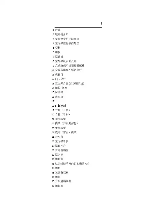
1玻璃2镀锌钢角码3室外铝型材表面处理4室内铝型材表面处理5型材6铝板7铝背板8室外铝板表面处理9点式玻璃不锈钢接驳螺栓10全玻幕墙和不锈钢部件11旋转门12门五金件13五金开启窗(多点锁系统)14螺栓/螺丝15保温棉16防火棉17181.铝型材19立柱(公料)20立柱(母料)21顶部横梁22横梁(开启期部份)23中挺横梁24底部(窗台)横梁25开启扇26室内铝罩板27铝百叶片28百叶窗铝框29铝副框30铝扣盖31以密封胶填充的铝水槽结构件32铝角33装饰条铝框34铝框35开启扇铝副框36铝扣盖建LEGEND OF MAERIALS37横向装饰条38横向装饰条托架39铝压条40内部装饰铝套41铝芯套42432.钢结构44由外墙承建商负责的钢结构45由工程师指定的焊缝46由总承建商负责的钢结构47矩形管48493.金属板材50指定颜色的铝板51不锈钢防鸟网52防烟涂料/板53铝盖54支撑防火材料用镀锌片55防水铝板56石材支撑铝槽57镀锌钢板58铝角59铝板支撑角铝60指定颜色的铝槽61风管连接套62634.托架64铝托架(含锯齿形定位垫片) 65热浸镀锌钢托架66预埋镀锌铁板/角码67铝制挂托架68铝套69铝角码70调节螺丝71供调节用长螺孔72限制板块移动的铝块73固定镀锌钢折板74755.紧固件(螺栓,螺母,垫圈)76不锈钢螺栓77不锈钢螺母78不锈钢垫圈79不锈钢弹簧垫圈80不锈钢自锁螺母81不锈钢自攻螺丝82不锈钢机器螺丝83不锈钢调整螺栓84多点锁85锁箱(手柄可拆卸)86不锈钢铆钉87清洁/维修铰索扣88射钉89后补锚栓90916.表面处理92氟碳喷涂处理93粉喷处理94涂漆钢结构95热镀锌钢结构96977.玻璃98中空玻璃(结构胶必须能承担设计风压) 99单层玻璃100夹胶玻璃1013M防爆膜1021038.密封胶104双组份结构密封胶105耐候胶106双面胶条107框架拼接密封胶108泡沫棒109单组份结构密封胶110密封胶密封111密气密封胶1121139.砖石结构114混凝土楼板/梁115混凝土反梁116楼板结构顶点11711810.填充材料119聚氯丁圆头胶条120聚氯丁耐候胶条121聚氯丁耐候雨披水胶条122硅酮玻璃/石材垫块123水汽隔断124与硅酮胶相容的橡胶垫块125可膨胀三元乙丙挤压型批水板12612711.绝缘材料128隔热材料129防火材料130隔热断桥(PA66)13113212.其它133泄水孔134等压孔135楼板建筑顶点136由外墙承包商负责的防水涂料137绝缘片138相应结构及湿度变形而预先采取的措施139由总承建商负责的结构140高强度塑胶/尼龙垫片(套)141卷帘护箱142通风管道由其它承包商承建143吊顶由其它承包商承建144石材145由其它承包商负责的防水层146由其它承包商负责的室内装饰147横梁后边线148外部竖向装饰条149立柱后边线150支撑铝板建筑材料符号表LEGEND OF MAERIALS(Glass)- LocalGMS bracket to kerfExtrusions Finishes ExteriorExtrusions Finishes InteriorAluminium ExtrusionAluminium PanelAluminium Back panExterior Aluminium panel finishStainless Steel Flush Bolt for point fixing glass Glass Wall and S/S ComponentsRevolving DoorDoor IronmongeryHardware - Operable Vents multipoint lockBolt/screwInsulationFirestopALUMINIUM EXTRUSIONMALE MULLIONFEMALE MULLIONHEAD EXTRUSIONTRANSOM WITH VENT SASHINTERMEDIATE TRANSOMSILL TRANSOMOPERABLE VENDALUMINIUM INTERIOR TRIMALUMINIUM LOUVRE BLADEALUMINIUM LOUVRE FRAMEALUMINIUM GLAZING ADAPTERALUMINIUM COVER DEADALUMINIUM STRUCTLRAL GUTTER SLEEVE SET IN SEALANT ALUMINIUM ANGLEALUMINIUM FEATURE FIN FRAMEALUMINIUM BOX SECTIONALUMINIUM CPERABLE VENT STOPALUMINIUM CLIP-ON COVERALUMINIUM HORIZONTAL PEATURE CAPPING HORIZONTAL FEATURE FIN BRACKETALUMINIUM PRESSUREALUMINIUM INTERIOR TRIM SLEEVEALUMINIUM STRUCTLRAL SLEEVESTEELWORKSECONDARY STEEL BY FACADE CONTRACTORWELDING AS NOMINATED BY ENGINEERSTEEL BY MAIN CONTRACTORSTEEL BOX SECTIONSHEET METALFORMED ALUMINIUM SHEET TO SELECTED COLOUR STAINLESS STEEL BIRDWIRE MESHSMOKE SEAL/FLASHINGALUMINIUM FORMED CAPPINGFIRE INSULATION SUPPORT BRACKET (GALANIZED STEEL ALUMINIUM FLASHINGPRESSED ALUMINIUM STONE SUPPORT CHANNEL FORMED GSM SHEETPRESSING ALUMINIUM ANGLEALUMINIUM CAPPING SUPPORTPRESSED ALUMINIUM CHANNEL TO SELECTED COLOUR DUCT CONNECTING SLEEVEBRACKETALUMINIUM BRACKET (W/SERRATED WASHER) GALVANISED STEEL BRACKETCAST-IN GALVANISED STEEL PLATE/ANGLE ALUMINIUM HOOK-ON BRACKETALUMINIUM SLEEVEALUMINIUM ANGLE BRACKETADJUSTMENT SCREWSLOTTED HOLES FOR ADJUSTMENTANTI-UPLIFT BRACKETFORMED STEEL CHANNEL/ANGLEFIXING(BOLTS,NUTS,WASHERS)STAINLESS STEEL BOLTSTAINLESS STEEL NUTSTAINLESS STEEL WASHERSTAINLESS STEEL SPRING WASHERSTAINLESS STEEL SELF-LOCKING NUTSTAINLESS STEEL SELF-TAPPING SCREWSTAINLESS STEEL MACHINE SCREWSTAINLESS STEEL JACKING BOLTMULTI-POINT LOCKING DEVICELOCK BOX W/REMOVABLE HANDELSTAINLESS STEEL POP RIVETCLEANING/MAINTENANCE GONDOLA LANYARO RESTRAINTSHOT PINMASONARY ANCHORFINISHPVF2 FINISHPOWER COAT FINISHPAINTED STEELHOT DIPPED GALVANISED STEELGLASSDOUBLE GLAZED UNIT (STRUCTURAL SEALANT MUST TAKE DESIGN WIND LOADMONOLITHIC GLASSLAMINATED GLASS3M FILMSEALANTSTWO-PART STRUCTURAL SEALANTWEATHER SEAL SEALANTDOUBLED SIDED TAPEFRAME JOINT SEALANTSEALANT BACKER RODONE-PART STRUCTURAL SEALANTSILICONE SEALEDAIR SEALMASONRYCONCRETE SLAB/BEAMCONCRETE UPSTANDTOP OF SLABGASKETNEOPRENE BULB GASKETNEOPRENE WEATHER SEAL GASKETNEOPRENE RAIN-SCREEN FLAPSILICONE GLASS/STONE SETTING BLOCKAIR & WATER BAFFLESILICONE COMPATIBLE HARD DUROMETER RUBBER SHIM EXTRUDED EPDM EXPANDABLE FLASHINGINSULATIONTHERMAL INSULATIONFIRE INSULATOINTHERMAL BREAK(PA66)MISCELLANEOUSWEEPHOLEPRESSURE EQUALIZATION HOLETOP OF FINISHED FLOORWATERPROOFING BY FACADE CONTRACTORISOLATION SHIM/TAPEPROVISION FOR BUILDING & THERMAL MOVEMENT STRUCTURE BY MAIN CONTRACTORHIGH IMPACT PLASTIC/NYLON SHIM OR SLEEVE BLIND BOXDUCT WORK BY OTHERSSUSPENOED CEILING BY OTHERSTONE PANELWATERPROOFING BY OTHERSINTERIOR FINISH BY OTHERSBACK OF TRANSOM EXTRUSIONEXTERNAL VERTICAL FEATURE FINBACK OF MULLIONALUMINIUM DEAD LOAD BLOCK。
1玻璃2镀锌钢角码3室外铝型材表面处理4室内铝型材表面处理5型材6铝板7铝背板8室外铝板表面处理9点式玻璃不锈钢接驳螺栓10全玻幕墙和不锈钢部件11旋转门12门五金件13五金开启窗(多点锁系统)14螺栓/螺丝15保温棉16防火棉17181.铝型材19立柱(公料)20立柱(母料)21顶部横梁22横梁(开启期部份)23中挺横梁24底部(窗台)横梁25开启扇26室内铝罩板27铝百叶片28百叶窗铝框29铝副框30铝扣盖31以密封胶填充的铝水槽结构件32铝角33装饰条铝框34铝框35开启扇铝副框36铝扣盖建LEGEND OF MAERIALS37横向装饰条38横向装饰条托架39铝压条40内部装饰铝套41铝芯套42432.钢结构44由外墙承建商负责的钢结构45由工程师指定的焊缝46由总承建商负责的钢结构47矩形管48493.金属板材50指定颜色的铝板51不锈钢防鸟网52防烟涂料/板53铝盖54支撑防火材料用镀锌片55防水铝板56石材支撑铝槽57镀锌钢板58铝角59铝板支撑角铝60指定颜色的铝槽61风管连接套62634.托架64铝托架(含锯齿形定位垫片) 65热浸镀锌钢托架66预埋镀锌铁板/角码67铝制挂托架68铝套69铝角码70调节螺丝71供调节用长螺孔72限制板块移动的铝块73固定镀锌钢折板74755.紧固件(螺栓,螺母,垫圈)76不锈钢螺栓77不锈钢螺母78不锈钢垫圈79不锈钢弹簧垫圈80不锈钢自锁螺母81不锈钢自攻螺丝82不锈钢机器螺丝83不锈钢调整螺栓84多点锁85锁箱(手柄可拆卸)86不锈钢铆钉87清洁/维修铰索扣88射钉89后补锚栓90916.表面处理92氟碳喷涂处理93粉喷处理94涂漆钢结构95热镀锌钢结构96977.玻璃98中空玻璃(结构胶必须能承担设计风压) 99单层玻璃100夹胶玻璃1013M防爆膜1021038.密封胶104双组份结构密封胶105耐候胶106双面胶条107框架拼接密封胶108泡沫棒109单组份结构密封胶110密封胶密封111密气密封胶1121139.砖石结构114混凝土楼板/梁115混凝土反梁116楼板结构顶点11711810.填充材料119聚氯丁圆头胶条120聚氯丁耐候胶条121聚氯丁耐候雨披水胶条122硅酮玻璃/石材垫块123水汽隔断124与硅酮胶相容的橡胶垫块125可膨胀三元乙丙挤压型批水板12612711.绝缘材料128隔热材料129防火材料130隔热断桥(PA66)13113212.其它133泄水孔134等压孔135楼板建筑顶点136由外墙承包商负责的防水涂料137绝缘片138相应结构及湿度变形而预先采取的措施139由总承建商负责的结构140高强度塑胶/尼龙垫片(套)141卷帘护箱142通风管道由其它承包商承建143吊顶由其它承包商承建144石材145由其它承包商负责的防水层146由其它承包商负责的室内装饰147横梁后边线148外部竖向装饰条149立柱后边线150支撑铝板建筑材料符号表LEGEND OF MAERIALS(Glass)- LocalGMS bracket to kerfExtrusions Finishes ExteriorExtrusions Finishes InteriorAluminium ExtrusionAluminium PanelAluminium Back panExterior Aluminium panel finishStainless Steel Flush Bolt for point fixing glass Glass Wall and S/S ComponentsRevolving DoorDoor IronmongeryHardware - Operable Vents multipoint lockBolt/screwInsulationFirestopALUMINIUM EXTRUSIONMALE MULLIONFEMALE MULLIONHEAD EXTRUSIONTRANSOM WITH VENT SASHINTERMEDIATE TRANSOMSILL TRANSOMOPERABLE VENDALUMINIUM INTERIOR TRIMALUMINIUM LOUVRE BLADEALUMINIUM LOUVRE FRAMEALUMINIUM GLAZING ADAPTERALUMINIUM COVER DEADALUMINIUM STRUCTLRAL GUTTER SLEEVE SET IN SEALANT ALUMINIUM ANGLEALUMINIUM FEATURE FIN FRAMEALUMINIUM BOX SECTIONALUMINIUM CPERABLE VENT STOPALUMINIUM CLIP-ON COVERALUMINIUM HORIZONTAL PEATURE CAPPING HORIZONTAL FEATURE FIN BRACKETALUMINIUM PRESSUREALUMINIUM INTERIOR TRIM SLEEVEALUMINIUM STRUCTLRAL SLEEVESTEELWORKSECONDARY STEEL BY FACADE CONTRACTORWELDING AS NOMINATED BY ENGINEERSTEEL BY MAIN CONTRACTORSTEEL BOX SECTIONSHEET METALFORMED ALUMINIUM SHEET TO SELECTED COLOUR STAINLESS STEEL BIRDWIRE MESHSMOKE SEAL/FLASHINGALUMINIUM FORMED CAPPINGFIRE INSULATION SUPPORT BRACKET (GALANIZED STEEL ALUMINIUM FLASHINGPRESSED ALUMINIUM STONE SUPPORT CHANNEL FORMED GSM SHEETPRESSING ALUMINIUM ANGLEALUMINIUM CAPPING SUPPORTPRESSED ALUMINIUM CHANNEL TO SELECTED COLOUR DUCT CONNECTING SLEEVEBRACKETALUMINIUM BRACKET (W/SERRATED WASHER) GALVANISED STEEL BRACKETCAST-IN GALVANISED STEEL PLATE/ANGLE ALUMINIUM HOOK-ON BRACKETALUMINIUM SLEEVEALUMINIUM ANGLE BRACKETADJUSTMENT SCREWSLOTTED HOLES FOR ADJUSTMENTANTI-UPLIFT BRACKETFORMED STEEL CHANNEL/ANGLEFIXING(BOLTS,NUTS,WASHERS)STAINLESS STEEL BOLTSTAINLESS STEEL NUTSTAINLESS STEEL WASHERSTAINLESS STEEL SPRING WASHERSTAINLESS STEEL SELF-LOCKING NUTSTAINLESS STEEL SELF-TAPPING SCREWSTAINLESS STEEL MACHINE SCREWSTAINLESS STEEL JACKING BOLTMULTI-POINT LOCKING DEVICELOCK BOX W/REMOVABLE HANDELSTAINLESS STEEL POP RIVETCLEANING/MAINTENANCE GONDOLA LANYARO RESTRAINTSHOT PINMASONARY ANCHORFINISHPVF2 FINISHPOWER COAT FINISHPAINTED STEELHOT DIPPED GALVANISED STEELGLASSDOUBLE GLAZED UNIT (STRUCTURAL SEALANT MUST TAKE DESIGN WIND LOADMONOLITHIC GLASSLAMINATED GLASS3M FILMSEALANTSTWO-PART STRUCTURAL SEALANTWEATHER SEAL SEALANTDOUBLED SIDED TAPEFRAME JOINT SEALANTSEALANT BACKER RODONE-PART STRUCTURAL SEALANTSILICONE SEALEDAIR SEALMASONRYCONCRETE SLAB/BEAMCONCRETE UPSTANDTOP OF SLABGASKETNEOPRENE BULB GASKETNEOPRENE WEATHER SEAL GASKETNEOPRENE RAIN-SCREEN FLAPSILICONE GLASS/STONE SETTING BLOCKAIR & WATER BAFFLESILICONE COMPATIBLE HARD DUROMETER RUBBER SHIM EXTRUDED EPDM EXPANDABLE FLASHINGINSULATIONTHERMAL INSULATIONFIRE INSULATOINTHERMAL BREAK(PA66)MISCELLANEOUSWEEPHOLEPRESSURE EQUALIZATION HOLETOP OF FINISHED FLOORWATERPROOFING BY FACADE CONTRACTORISOLATION SHIM/TAPEPROVISION FOR BUILDING & THERMAL MOVEMENT STRUCTURE BY MAIN CONTRACTORHIGH IMPACT PLASTIC/NYLON SHIM OR SLEEVE BLIND BOXDUCT WORK BY OTHERSSUSPENOED CEILING BY OTHERSTONE PANELWATERPROOFING BY OTHERSINTERIOR FINISH BY OTHERSBACK OF TRANSOM EXTRUSIONEXTERNAL VERTICAL FEATURE FINBACK OF MULLIONALUMINIUM DEAD LOAD BLOCK。
建筑外文翻译外文文献英文文献混凝土强度和现代建筑材料以下是为大家整理的建筑外文翻译外文文献英文文献混凝土强度和现代建筑材料的相关范文,本文关键词为建筑,外文,翻译,文献,英文,混凝土,强度,现代,建筑材料,,您可以从右上方搜索框检索更多相关文章,如果您觉得有用,请继续关注我们并推荐给您的好友,您可以在英语学习中查看更多范文。
外文出处:buildingandenvironment12(20XX)186-191附件1:外文资料翻译译文混凝土强度和现代建筑材料文章摘要:钢筋混凝土可以用在框架结构上,常常用在预制构件并主要用在工业建筑相同结构建筑物上,混凝土也可以用在壳式建筑施工中,其表面同时也成为结构的组成部分。
现代建筑材料:大多数较大的建筑物都是由钢结构,钢筋混凝土以及预应力混凝土构成。
关键词:混凝土强度;现代建筑材料;高层建筑;框架结构在许多结构中,混凝土同时受到不同方向各种应力的作用.例如在梁中大部分混凝土同时承受压力和剪力,再楼板和基础中,混凝土同时承受两个相互垂直方向的压力外加剪力的作用.根据材料力学学习中已知的方法,无论怎样复杂的复合应力状态,都可化为三个相互垂直的主应力,它们作用在材料适当定向的单元立方体上.三个主应力中的任意一个或者全部既可是拉应力,也可是压应力.如果其中一个主应力为零,则为双轴应力状态。
如果有两个主应力为零,则为单轴应力状态,或为简单压缩或为简单拉伸。
在多数情况下,根据简单的试验,如圆柱体强度f'c和抗拉强度f't,只能够确定材料在单轴应力作用下的性能。
为了预测混凝土在双轴应力或三轴应力作用下的结构强度,在通过试验仅仅知道f'c或f'c与f't的情况下,需要通过计算确定混凝土在上述复合应力状态下的强度。
尽管人们连续不断地进行了大量的研究,但仍然没有得出有关混凝土在复合应力作用下的强度的通用理论。
经过修正的各种强度理论,如最大拉应力理论、莫尔-库仑理论和八面体应力理论(以上理论都在材料力学课本中讨论过)应用于混凝土,取得了不同程度的进展。
forced concrete structure reinforced with anoverviewReinSince the reform and opening up, with the national economy's rapid and sustained development of a reinforced concrete structure built, reinforced with the development of technology has been great. Therefore, to promote the use of advanced technology reinforced connecting to improve project quality and speed up the pace of construction, improve labor productivity, reduce costs, and is of great significance.Reinforced steel bars connecting technologies can be divided into two broad categories linking welding machinery and steel. There are six types of welding steel welding methods, and some apply to the prefabricated plant, and some apply to the construction site, some of both apply. There are three types of machinery commonly used reinforcement linking method primarily applicable to the construction site. Ways has its own characteristics and different application, and in the continuous development and improvement. In actual production, should be based on specific conditions of work, working environment and technical requirements, the choice of suitable methods to achieve the best overall efficiency.1、steel mechanical link1.1 radial squeeze linkWill be a steel sleeve in two sets to the highly-reinforced Department with superhigh pressure hydraulic equipment (squeeze tongs) along steel sleeve radial squeeze steel casing, in squeezing out tongs squeeze pressure role of a steel sleeve plasticity deformation closely integrated with reinforced through reinforced steel sleeve and Wang Liang's Position will be two solid steel bars linkedCharacteristic: Connect intensity to be high, performance reliable, can bear high stress draw and pigeonhole the load and tired load repeatedly.Easy and simple to handle, construction fast, save energy and material, comprehensive economy profitable, this method has been already a large amount of application in the project.Applicable scope : Suitable for Ⅱ, Ⅲ, Ⅳgrade reinforcing bar (including welding bad reinfor cing bar ) with ribbing of Ф 18- 50mm, connection between the same diameter or different diameters reinforcing bar .1.2must squeeze linkExtruders used in the covers, reinforced axis along the cold metal sleeve squeeze dedicated to insert sleeve Lane two hot rolling steel drums into a highly integrated mechanical linking methods.Characteristic: Easy to operate and joining fast and not having flame homework , can construct for 24 hours , save a large number of reinforcing bars and energy. Applicable scope : Suitable for , set up according to first and second class antidetonation requirement -proof armored concrete structure ФⅡ, Ⅲgrade reinforcing bar with ribbing of hot rolling of 20- 32mm join and construct live.1.3 cone thread connectingUsing cone thread to bear pulled, pressed both effort and self-locking nature, undergo good principles will be reinforced by linking into cone-processing thread at the moment the value of integration into the joints connecting steel bars.Characteristic: Simple , all right preparatory cut of the craft , connecting fast, concentricity is good, have pattern person who restrain from advantage reinforcing bar carbon content.Applicable scope : Suitable for the concrete structure of the industry , civil buil ding and general structures, reinforcing bar diameter is for Фfor the the 16- 40mm one Ⅱ, Ⅲgrade verticality, it is the oblique to or reinforcing bars horizontal join construct live.conclusionsThese are now commonly used to connect steel synthesis methods, which links technology in the United States, Britain, Japan and other countries are widely used. There are different ways to connect their different characteristics and scope of the actual construction of production depending on the specific project choose a suitable method of connecting to achieve both energy conservation and saving time limit for a project ends.钢筋混凝土构造中钢筋连接综述改革开放以来,伴随国民经济旳迅速、持久发展,多种钢筋混凝土建筑构造大量建造,钢筋连接技术得到很大旳发展。
外文文献翻译原文Analysis of Con tin uous Prestressed Concrete BeamsChris BurgoyneMarch 26, 20051、IntroductionThis conference is devoted to the development of structural analysis rather than the strength of materials, but the effective use of prestressed concrete relies on an appropriate combination of structural analysis techniques with knowledge of the material behaviour. Design of prestressed concrete structures is usually left to specialists; the unwary will either make mistakes or spend inordinate time trying to extract a solution from the various equations.There are a number of fundamental differences between the behaviour of prestressed concrete and that of other materials. Structures are not unstressed when unloaded; the design space of feasible solutions is totally bounded;in hyperstatic structures, various states of self-stress can be induced by altering the cable profile, and all of these factors get influenced by creep and thermal effects. How were these problems recognised and how have they been tackled?Ever since the development of reinforced concrete by Hennebique at the end of the 19th century (Cusack 1984), it was recognised that steel and concrete could be more effectively combined if the steel was pretensioned, putting the concrete into compression. Cracking could be reduced, if not prevented altogether, which would increase stiffness and improve durability. Early attempts all failed because the initial prestress soon vanished, leaving the structure to be- have as though it was reinforced; good descriptions of these attempts are given by Leonhardt (1964) and Abeles (1964).It was Freyssineti’s observations of the sagging of the shallow arches on three bridges that he had just completed in 1927 over the River Allier near Vichy which led directly to prestressed concrete (Freyssinet 1956). Only the bridge at Boutiron survived WWII (Fig 1). Hitherto, it had been assumed that concrete had a Young’s modulus which remained fixed, but he recognised that the de- ferred strains due to creep explained why the prestress had been lost in the early trials. Freyssinet (Fig. 2) also correctly reasoned that high tensile steel had to be used, so that some prestress would remain after the creep had occurred, and alsothat high quality concrete should be used, since this minimised the total amount of creep. The history of Freyssineti’s early prestressed concrete work is written elsewhereFigure1:Boutiron Bridge,Vic h yFigure 2: Eugen FreyssinetAt about the same time work was underway on creep at the BRE laboratory in England ((Glanville 1930) and (1933)). It is debatable which man should be given credit for the discovery of creep but Freyssinet clearly gets the credit for successfully using the knowledge to prestress concrete.There are still problems associated with understanding how prestressed concrete works, partly because there is more than one way of thinking about it. These different philosophies are to some extent contradictory, and certainly confusing to the young engineer. It is also reflected, to a certain extent, in the various codes of practice.Permissible stress design philosophy sees prestressed concrete as a way of avoiding cracking by eliminating tensile stresses; the objective is for sufficient compression to remain after creep losses. Untensionedreinforcement, which attracts prestress due to creep, is anathema. This philosophy derives directly from Freyssinet’s logic and is primarily a working stress concept.Ultimate strength philosophy sees prestressing as a way of utilising high tensile steel as reinforcement. High strength steels have high elastic strain capacity, which could not be utilised when used as reinforcement; if the steel is pretensioned, much of that strain capacity is taken out before bonding the steel to the concrete. Structures designed this way are normally designed to be in compression everywhere under permanent loads, but allowed to crack under high live load. The idea derives directly from the work of Dischinger (1936) and his work on the bridge at Aue in 1939 (Schonberg and Fichter 1939), as well as that of Finsterwalder (1939). It is primarily an ultimate load concept. The idea of partial prestressing derives from these ideas.The Load-Balancing philosophy, introduced by T.Y. Lin, uses prestressing to counter the effect of the permanent loads (Lin 1963). The sag of the cables causes an upward force on the beam, which counteracts the load on the beam. Clearly, only one load can be balanced, but if this is taken as the total dead weight, then under that load the beam will perceive only the net axial prestress and will have no tendency to creep up or down.These three philosophies all have their champions, and heated debates take place between them as to which is the most fundamental.2、Section designFrom the outset it was recognised that prestressed concrete has to be checked at both the working load and the ultimate load. For steel structures, and those made from reinforced concrete, there is a fairly direct relationship between the load capacity under an allowable stress design, and that at the ultimate load under an ultimate strength design. Older codes were based on permissible stresses at the working load; new codes use moment capacities at the ultimate load. Different load factors are used in the two codes, but a structure which passes one code is likely to be acceptable under the other.For prestressed concrete, those ideas do not hold, since the structure is highly stressed, even when unloaded. A small increase of load can cause some stress limits to be breached, while a large increase in load might be needed to cross other limits. The designer has considerable freedom to vary both the working load and ultimate load capacities independently; both need to be checked.A designer normally has to check the tensile and compressive stresses, in both the top and bottom fibre of the section, for every load case. The critical sections are normally, but not always, the mid-span and the sections over piers but other sections may become critical ,when the cable profile has to be determined.The stresses at any position are made up of three components, one of which normally has a different sign from the other two; consistency of sign convention is essential.If P is the prestressing force and e its eccentricity, A and Z are the area of the cross-section and its elastic section modulus, while M is the applied moment, then where ft and fc are the permissible stresses in tension and compression.c e t f ZM Z P A P f ≤-+≤Thus, for any combination of P and M , the designer already has four in- equalities to deal with.The prestressing force differs over time, due to creep losses, and a designer isusually faced with at least three combinations of prestressing force and moment;• the applied moment at the time the prestress is first applied, before creep losses occur,• the maximum applied moment after creep losses, and• the minimum applied moment after creep losses.Figure 4: Gustave MagnelOther combinations may be needed in more complex cases. There are at least twelve inequalities that have to be satisfied at any cross-section, but since an I-section can be defined by six variables, and two are needed to define the prestress, the problem is over-specified and it is not immediately obvious which conditions are superfluous. In the hands of inexperienced engineers, the design process can be very long-winded. However, it is possible to separate out the design of the cross-section from the design of the prestress. By considering pairs of stress limits on the same fibre, but for different load cases, the effects of the prestress can be eliminated, leaving expressions of the form:rangestress e Perm issibl Range Mom entZ These inequalities, which can be evaluated exhaustively with little difficulty, allow the minimum size of the cross-section to be determined.Once a suitable cross-section has been found, the prestress can be designed using a construction due to Magnel (Fig.4). The stress limits can all be rearranged into the form:()M fZ PA Z e ++-≤1 By plotting these on a diagram of eccentricity versus the reciprocal of the prestressing force, a series of bound lines will be formed. Provided the inequalities (2) are satisfied, these bound lines will always leave a zone showing all feasible combinations of P and e. The most economical design, using the minimum prestress, usually lies on the right hand side of the diagram, where the design is limited by the permissible tensile stresses.Plotting the eccentricity on the vertical axis allows direct comparison with the crosssection, as shown in Fig. 5. Inequalities (3) make no reference to the physical dimensions of the structure, but these practical cover limits can be shown as wellA good designer knows how changes to the design and the loadings alter the Magnel diagram. Changing both the maximum andminimum bending moments, but keeping the range the same, raises and lowers the feasible region. If the moments become more sagging the feasible region gets lower in the beam.In general, as spans increase, the dead load moments increase in proportion to the live load. A stage will be reached where the economic point (A on Fig.5) moves outside the physical limits of the beam; Guyon (1951a) denoted the limiting condition as the critical span. Shorter spans will be governed by tensile stresses in the two extreme fibres, while longer spans will be governed by the limiting eccentricity and tensile stresses in the bottom fibre. However, it does not take a large increase in moment ,at which point compressive stresses will govern in the bottom fibre under maximum moment.Only when much longer spans are required, and the feasible region moves as far down as possible, does the structure become governed by compressive stresses in both fibres.3、Continuous beamsThe design of statically determinate beams is relatively straightforward; the engineer can work on the basis of the design of individual cross-sections, as outlined above. A number of complications arise when the structure is indeterminate which means that the designer has to consider, not only a critical section,but also the behaviour of the beam as a whole. These are due to the interaction of a number of factors, such as Creep, Temperature effects and Construction Sequence effects. It is the development of these ideas whichforms the core of this paper. The problems of continuity were addressed at a conference in London (Andrew and Witt 1951). The basic principles, and nomenclature, were already in use, but to modern eyes concentration on hand analysis techniques was unusual, and one of the principle concerns seems to have been the difficulty of estimating losses of prestressing force.3.1 Secondary MomentsA prestressing cable in a beam causes the structure to deflect. Unlike the statically determinate beam, where this motion is unrestrained, the movement causes a redistribution of the support reactions which in turn induces additional moments. These are often termed Secondary Moments, but they are not always small, or Parasitic Moments, but they are not always bad.Freyssinet’s bridge across the Marne at Luzancy, started in 1941 but not completed until 1946, is often thought of as a simply supported beam, but it was actually built as a two-hinged arch (Harris 1986), with support reactions adjusted by means of flat jacks and wedges which were later grouted-in (Fig.6). The same principles were applied in the later and larger beams built over the same river.Magnel built the first indeterminate beam bridge at Sclayn, in Belgium (Fig.7) in 1946. The cables are virtually straight, but he adjusted the deck profile so that the cables were close to the soffit near mid-span. Even with straight cables the sagging secondary momentsare large; about 50% of the hogging moment at the central support caused by dead and live load.The secondary moments cannot be found until the profile is known but the cablecannot be designed until the secondary moments are known. Guyon (1951b) introduced the concept of the concordant profile, which is a profile that causes no secondary moments; es and ep thus coincide. Any line of thrust is itself a concordant profile.The designer is then faced with a slightly simpler problem; a cable profile has to be chosen which not only satisfies the eccentricity limits (3) but is also concordant. That in itself is not a trivial operation, but is helped by the fact that the bending moment diagram that results from any load applied to a beam will itself be a concordant profile for a cable of constant force. Such loads are termed notional loads to distinguish them from the real loads on the structure. Superposition can be used to progressively build up a set of notional loads whose bending moment diagram gives the desired concordant profile.3.2 Temperature effectsTemperature variations apply to all structures but the effect on prestressed concrete beams can be more pronounced than in other structures. The temperature profile through the depth of a beam (Emerson 1973) can be split into three components for the purposes of calculation (Hambly 1991). The first causes a longitudinal expansion, which is normally released by the articulation of the structure; the second causes curvature which leads to deflection in all beams and reactant moments in continuous beams, while the third causes a set of self-equilibrating set of stresses across the cross-section.The reactant moments can be calculated and allowed-for, but it is the self- equilibrating stresses that cause the main problems for prestressed concrete beams. These beams normally have high thermal mass which means that daily temperature variations do not penetrate to the core of the structure. The result is a very non-uniform temperature distribution across the depth which in turn leads to significant self-equilibrating stresses. If the core of the structure is warm, while the surface is cool, such as at night, then quite large tensile stresses can be developed on the top and bottom surfaces. However, they only penetrate a very short distance into the concrete and the potential crack width is very small. It can be very expensive to overcome the tensile stress by changing the section or the prestress。
中文译文:建筑业的竞争及竞争策略美国的工程建筑公司几十年来一直控制着国际建筑市场,但近来世界上发生的事件改变了它的主导地位。
为了调查今后十年对工程建筑竞争产生影响的推动力及趋势,由建筑工业研究院的"2000年建筑特别工作组:发起一项称为“2000年建筑市场竞争分析”的研究项目。
该研究项目考察了一些影响竞争的因素,包括下列方面:企业能力塑造:采用纵向联合,横向发展的方法,提高企业的综合能力。
扩大市场领地,这种做法包括被海外的联合企业收购或被其合并,或是由美国公司收购外国公司。
筹措资金的选择方法:私有化作用,建筑权力转让项目,未来市场中工程筹资特征。
管理、组织及结构:未来的经营管理及组织方法、组织结构、组织技巧要有利于引导职员在世界竞争环境中发挥作用。
劳力特征:未来具有专业水平和技工水平的工程建筑工人的供求情况技术问题:技术将如何影响竞争,如何用来弥补劳力不足的缺陷。
研究目标及范围这一研究项目的目标是收集信息,使之为适应2000年及以后的工程建筑业在调整、制定策略方面的需要提供真知灼见,并制定出2000年工程建筑业的可能的发展计划。
这项研究回顾了工程建筑业的历史过程,审视了当前的发展趋势,以确定影响该工业未来的推动力,与该工业相关的有重塑企业能力,私有化及筹措资金方法的潜在作用以及经营管理、组织方法、公司结构方面的未来发展方向。
研究范围包括选定一些公司,采访这些公司有专业特长的人员。
这些人员的专业涉及面很广,包括商业建筑,重工业建筑,公共事业设施建设,基础建设.轻工业建筑,电力,生产程序以及航天科学。
工程建筑业竞争特性工程建筑业的竞争特征由于下列原因在变动:80年代发生的事件,以及计划在90年代实施的项目,正在引导建筑业摆脱相互对立的局面,转向相互合作。
应该以积极的眼光看待新的公司进入国际工程建筑市场,因为它增加了全球合作的机遇。
合作关系会使所有的伙伴受益,这是因为美国公司可以在合作伙伴的国家找到机遇,同样,外国公司也会打入美国市场。
1玻璃2镀锌钢角码3室外铝型材表面处理4室内铝型材表面处理5型材6铝板7铝背板8室外铝板表面处理9点式玻璃不锈钢接驳螺栓10全玻幕墙和不锈钢部件11旋转门12门五金件13五金开启窗(多点锁系统)14螺栓/螺丝15保温棉16防火棉17181.铝型材19立柱(公料)20立柱(母料)21顶部横梁22横梁(开启期部份)23中挺横梁24底部(窗台)横梁25开启扇26室内铝罩板27铝百叶片28百叶窗铝框29铝副框30铝扣盖31以密封胶填充的铝水槽结构件32铝角33装饰条铝框34铝框35开启扇铝副框36铝扣盖建LEGEND OF MAERIALS37横向装饰条38横向装饰条托架39铝压条40内部装饰铝套41铝芯套42432.钢结构44由外墙承建商负责的钢结构45由工程师指定的焊缝46由总承建商负责的钢结构47矩形管48493.金属板材50指定颜色的铝板51不锈钢防鸟网52防烟涂料/板53铝盖54支撑防火材料用镀锌片55防水铝板56石材支撑铝槽57镀锌钢板58铝角59铝板支撑角铝60指定颜色的铝槽61风管连接套62634.托架64铝托架(含锯齿形定位垫片) 65热浸镀锌钢托架66预埋镀锌铁板/角码67铝制挂托架68铝套69铝角码70调节螺丝71供调节用长螺孔72限制板块移动的铝块73固定镀锌钢折板74755.紧固件(螺栓,螺母,垫圈)76不锈钢螺栓77不锈钢螺母78不锈钢垫圈79不锈钢弹簧垫圈80不锈钢自锁螺母81不锈钢自攻螺丝82不锈钢机器螺丝83不锈钢调整螺栓84多点锁85锁箱(手柄可拆卸)86不锈钢铆钉87清洁/维修铰索扣88射钉89后补锚栓90916.表面处理92氟碳喷涂处理93粉喷处理94涂漆钢结构95热镀锌钢结构96977.玻璃98中空玻璃(结构胶必须能承担设计风压) 99单层玻璃100夹胶玻璃1013M防爆膜1021038.密封胶104双组份结构密封胶105耐候胶106双面胶条107框架拼接密封胶108泡沫棒109单组份结构密封胶110密封胶密封111密气密封胶1121139.砖石结构114混凝土楼板/梁115混凝土反梁116楼板结构顶点11711810.填充材料119聚氯丁圆头胶条120聚氯丁耐候胶条121聚氯丁耐候雨披水胶条122硅酮玻璃/石材垫块123水汽隔断124与硅酮胶相容的橡胶垫块125可膨胀三元乙丙挤压型批水板12612711.绝缘材料128隔热材料129防火材料130隔热断桥(PA66)13113212.其它133泄水孔134等压孔135楼板建筑顶点136由外墙承包商负责的防水涂料137绝缘片138相应结构及湿度变形而预先采取的措施139由总承建商负责的结构140高强度塑胶/尼龙垫片(套)141卷帘护箱142通风管道由其它承包商承建143吊顶由其它承包商承建144石材145由其它承包商负责的防水层146由其它承包商负责的室内装饰147横梁后边线148外部竖向装饰条149立柱后边线150支撑铝板建筑材料符号表LEGEND OF MAERIALS(Glass)- LocalGMS bracket to kerfExtrusions Finishes ExteriorExtrusions Finishes InteriorAluminium ExtrusionAluminium PanelAluminium Back panExterior Aluminium panel finishStainless Steel Flush Bolt for point fixing glass Glass Wall and S/S ComponentsRevolving DoorDoor IronmongeryHardware - Operable Vents multipoint lockBolt/screwInsulationFirestopALUMINIUM EXTRUSIONMALE MULLIONFEMALE MULLIONHEAD EXTRUSIONTRANSOM WITH VENT SASHINTERMEDIATE TRANSOMSILL TRANSOMOPERABLE VENDALUMINIUM INTERIOR TRIMALUMINIUM LOUVRE BLADEALUMINIUM LOUVRE FRAMEALUMINIUM GLAZING ADAPTERALUMINIUM COVER DEADALUMINIUM STRUCTLRAL GUTTER SLEEVE SET IN SEALANT ALUMINIUM ANGLEALUMINIUM FEATURE FIN FRAMEALUMINIUM BOX SECTIONALUMINIUM CPERABLE VENT STOPALUMINIUM CLIP-ON COVERALUMINIUM HORIZONTAL PEATURE CAPPING HORIZONTAL FEATURE FIN BRACKETALUMINIUM PRESSUREALUMINIUM INTERIOR TRIM SLEEVEALUMINIUM STRUCTLRAL SLEEVESTEELWORKSECONDARY STEEL BY FACADE CONTRACTORWELDING AS NOMINATED BY ENGINEERSTEEL BY MAIN CONTRACTORSTEEL BOX SECTIONSHEET METALFORMED ALUMINIUM SHEET TO SELECTED COLOUR STAINLESS STEEL BIRDWIRE MESHSMOKE SEAL/FLASHINGALUMINIUM FORMED CAPPINGFIRE INSULATION SUPPORT BRACKET (GALANIZED STEEL ALUMINIUM FLASHINGPRESSED ALUMINIUM STONE SUPPORT CHANNEL FORMED GSM SHEETPRESSING ALUMINIUM ANGLEALUMINIUM CAPPING SUPPORTPRESSED ALUMINIUM CHANNEL TO SELECTED COLOUR DUCT CONNECTING SLEEVEBRACKETALUMINIUM BRACKET (W/SERRATED WASHER) GALVANISED STEEL BRACKETCAST-IN GALVANISED STEEL PLATE/ANGLE ALUMINIUM HOOK-ON BRACKETALUMINIUM SLEEVEALUMINIUM ANGLE BRACKETADJUSTMENT SCREWSLOTTED HOLES FOR ADJUSTMENTANTI-UPLIFT BRACKETFORMED STEEL CHANNEL/ANGLEFIXING(BOLTS,NUTS,WASHERS)STAINLESS STEEL BOLTSTAINLESS STEEL NUTSTAINLESS STEEL WASHERSTAINLESS STEEL SPRING WASHERSTAINLESS STEEL SELF-LOCKING NUTSTAINLESS STEEL SELF-TAPPING SCREWSTAINLESS STEEL MACHINE SCREWSTAINLESS STEEL JACKING BOLTMULTI-POINT LOCKING DEVICELOCK BOX W/REMOVABLE HANDELSTAINLESS STEEL POP RIVETCLEANING/MAINTENANCE GONDOLA LANYARO RESTRAINTSHOT PINMASONARY ANCHORFINISHPVF2 FINISHPOWER COAT FINISHPAINTED STEELHOT DIPPED GALVANISED STEELGLASSDOUBLE GLAZED UNIT (STRUCTURAL SEALANT MUST TAKE DESIGN WIND LOADMONOLITHIC GLASSLAMINATED GLASS3M FILMSEALANTSTWO-PART STRUCTURAL SEALANTWEATHER SEAL SEALANTDOUBLED SIDED TAPEFRAME JOINT SEALANTSEALANT BACKER RODONE-PART STRUCTURAL SEALANTSILICONE SEALEDAIR SEALMASONRYCONCRETE SLAB/BEAMCONCRETE UPSTANDTOP OF SLABGASKETNEOPRENE BULB GASKETNEOPRENE WEATHER SEAL GASKETNEOPRENE RAIN-SCREEN FLAPSILICONE GLASS/STONE SETTING BLOCKAIR & WATER BAFFLESILICONE COMPATIBLE HARD DUROMETER RUBBER SHIM EXTRUDED EPDM EXPANDABLE FLASHINGINSULATIONTHERMAL INSULATIONFIRE INSULATOINTHERMAL BREAK(PA66)MISCELLANEOUSWEEPHOLEPRESSURE EQUALIZATION HOLETOP OF FINISHED FLOORWATERPROOFING BY FACADE CONTRACTORISOLATION SHIM/TAPEPROVISION FOR BUILDING & THERMAL MOVEMENT STRUCTURE BY MAIN CONTRACTORHIGH IMPACT PLASTIC/NYLON SHIM OR SLEEVE BLIND BOXDUCT WORK BY OTHERSSUSPENOED CEILING BY OTHERSTONE PANELWATERPROOFING BY OTHERSINTERIOR FINISH BY OTHERSBACK OF TRANSOM EXTRUSIONEXTERNAL VERTICAL FEATURE FINBACK OF MULLIONALUMINIUM DEAD LOAD BLOCK。
使用加固纤维聚合物增强混凝土梁的延性作者:Nabil F. Grace, George Abel-Sayed, Wael F. Ragheb摘要:一种为加强结构延性的新型单轴柔软加强质地的聚合物(FRP)已在被研究,开发和生产(在结构测试的中心在劳伦斯技术大学)。
这种织物是两种碳纤维和一种玻璃纤维的混合物,而且经过设计它们在受拉屈服时应变值较低,从而体现出伪延性的性能。
通过对八根混凝土梁在弯曲荷载作用下的加固和检测对研制中的织物的效果和延性进行了研究。
用现在常用的单向碳纤维薄片、织物和板进行加固的相似梁也进行了检测,以便同用研制中的织物加固梁进行性能上的比较。
这种织物经过设计具有和加固梁中的钢筋同时屈服的潜力,从而和未加固梁一样,它也能得到屈服台阶。
相对于那些用现在常用的碳纤维加固体系进行加固的梁,这种研制中的织物加固的梁承受更高的屈服荷载,并且有更高的延性指标。
这种研制中的织物对加固机制体现出更大的贡献。
关键词:混凝土,延性,纤维加固,变形介绍外贴粘合纤维增强聚合物(FRP)片和条带近来已经被确定是一种对钢筋混凝土结构进行修复和加固的有效手段。
关于应用外贴粘合FRP板、薄片和织物对混凝土梁进行变形加固的钢筋混凝土梁的性能,一些试验研究调查已经进行过报告。
Saadatmanesh和Ehsani(1991)检测了应用玻璃纤维增强聚合物(GFRP)板进行变形加固的钢筋混凝土梁的性能。
Ritchie等人(1991)检测了应用GFRP,碳纤维增强聚合物(CFRP)和G/CFRP板进行变形加固的钢筋混凝土梁的性能。
Grace等人(1999)和Triantafillou(1992)研究了应用CFRP薄片进行变形加固的钢筋混凝土梁的性能。
Norris,Saadatmanesh和Ehsani(1997)研究了应用单向CFRP薄片和CFRP织物进行加固的混凝土梁的性能。
在所有的这些研究中,加固的梁比未加固的梁承受更高的极限荷载。
建筑材料英文Building Materials。
Building materials are the foundation of any construction project. They play a crucial role in determining the strength, durability, and aesthetic appeal of a building. In this document, we will explore the different types of building materials commonly used in construction and their English names.1. Concrete。
Concrete is a versatile building material that is made up of cement, water, and aggregates such as sand and gravel. It is widely used in the construction of foundations, walls, and floors. Concrete is known for its strength and durability, making it an ideal choice for various construction projects.2. Steel。
Steel is another essential building material that is used in the construction of structures such as beams, columns, and frames. It is known for its high tensile strength and resistance to corrosion, making it suitable for use in a wide range of construction applications.3. Brick。
13建筑工程材料中英文对照表中文英文缩写阀轭Yoke外螺纹阀杆及有阀轭Outside screw & yoke OS & Y阀杆Stem内螺纹阀杆Inside screw IS阀轭套Yoke sleeve阀杆环Stem ring阀座Valve seat Body seat阀座环、密封圈Seat ring整体阀座Integral seat堆焊阀座Deposited seat阀芯(包括密封圈、杆等)Trim阀盘Dise阀盘密封圈Dise seat阀体Body阀盖Bonnet阀盖衬套Bonnet bush螺纹阀帽Screw cap螺纹阀盖Screw bonnet螺栓连接的阀盖Bolted bonnet BB活接阀盖(帽)Union bonnet c ap螺栓连接的阀帽Bolted cap BC焊接阀盖Welded bonnet WB本体阀杆密封Body stem seal石棉安全密封Asbestos emergency seal 倒密封Back seal 压力密封的阀盖Pressure seal bonnet动力操纵器Powered operator电动操纵器Electric motor operator气动操纵器Pneumatic operator液压操纵器Hydraulic operator快速操纵器(滑动阀杆)Quick-acting operator (sliding stem) 正齿轮传动Spur gear operated伞齿轮传动Bevel gear operated扳手操作Wrench operated链轮Chain wheel手轮Hand wheel手柄Hand level (Handle)气缸(或液压缸)操纵的Cylinder operated 链条操纵的Chain operated等径孔道Full bore, Full port异径孔道Reducing bore;Reduced port Venturi port短型Short pattern紧凑型(小型)Compact type笼式环Lantern ring压盖Gland阀杆填料Stem packing阀盖垫片Bonnet gasket升杆式(明杆)Rising stem RS非升杆式(暗杆)Non-rising stem NRS开闭指示器/限位器Indicator/stopper注油器Grease injector可更换的阀座环Renewable seat ring闸阀Gate valve平行双闸板Double disc parallel seat楔形双闸板Split wedge挠性楔形闸板Flexible solid wedge楔形单闸板Solid wedge塞型闸阀Plug gate valve疏通型闸阀Through conduit gate valve截止阀Globe valve球心型阀盘Globe type disc塞型阀盘Plug type disc可转动的阀盘Swivel disc节流阀Throttle valve针阀Needle valve角阀(角式截止阀)Angle valveY型阀(Y型阀体截止阀)Y-valve (Y-body globe valve)球阀Ball valve三通球阀3-way ball valve装有底轴的Thunnion mounted耐火型Fire safe type浮动球型Floating ball type防脱出阀杆Blowout Proof stem蝶阀Butterfly valve对夹式(薄片型)Wafer type凸耳式Lug type偏心阀板蝶阀Offset disc butterfly valve; Eccentric butterfly valve斜阀盘蝶阀Canted disc butterfly valve连杆式蝶阀Link butterfly valve止回式蝶阀Combined non-return butterfly valve柱塞阀Piston type valve旋塞阀Plug valve三通旋塞阀Three-way plug valve四通旋塞阀Four-way plug valve旋塞Cock衬套旋塞Sleeve cock隔膜阀Diaphragm valve橡胶衬里隔膜阀Rubber lined diaphragm valve直通式隔膜阀Straight way diaphragm valve堰式隔膜阀Weir diaphragm valve夹紧式胶管阀Pinch valve (用于泥浆、粉尘等)止回阀Check valve升降式止回阀Lift check valve旋启式止回阀Swing check valve落球式止回阀Ball check valve弹簧球式止回阀Spring ball check valve双板对夹式止回阀Dual plate wafer type check valve无撞击声止回阀Non-slam check valve底阀Foot valve切断式止回阀Stop check valve ; Non-return valve活塞式止回阀Pistonche check valve翻板式止回阀Flap check valve翻转盘止回阀Tilting disc check valve蝶式止回阀Butterfly check valve安全泄气阀Safety valve SV安全泄液阀Relief valve RV安全泄压阀Safety relief valve杠杆重锤式Lever and weight type引导阀操纵的安全泄气阀Pilot operated safety valve复式安全泄气阀Twin type safety valve罐底排污阀Flush-bottom tank valve波纹管密封阀Bellow sealed valve电磁阀Solenoid valve; solenoid operated valve电动阀Electrically operated valve; Electr-motor operated valve气动阀Pneumatic operated valve低温用阀Cryogenic service valve 蒸汽疏止阀Steam trap机械式疏水阀Mechanical trap浮桶式疏水阀Open bucket trap; Open top bucket trap浮球式疏水阀Float trap倒吊桶式疏水阀Inverted bucket trap自由浮球式疏水阀Loose float trap恒温式疏水阀Thermostatic trap金属膨胀式蒸汽疏水阀Metal expansion steam trap液体膨胀式蒸汽疏水阀Liquid expansion steam trap双金属膨胀式蒸汽疏水阀Bimetallic expansion steam trap压力平衡式恒温疏水阀Balanced pressure thermostatic trap热动力式疏水阀Thermodynamic trap脉冲式蒸汽疏水阀Impulse steam trap放汽阀(自动放汽阀)Air vent valve; (Automatic air vent valve) 平板式滑动闸阀Slab type sliding gate valve 盖阀Flat valve换向阀Diverting valve; Reversing valve热膨胀阀Thermo expansion valve自动关闭阀Self-closing valve自动排液阀Self-draining valve管道肓板阀Line-blind valve挤压阀Sgueeze valve呼吸阀Breather valve风门Damper减压阀Pressure reducing valve; Reducing valve控制阀Control valve膜式控制阀Diaphrated operated control valve 执行机构Actuator背压调节阀Back pressure regulating valve差压调节阀Differential pressure regulating valve压力比例调节阀Pressure ratio regulating valve切断阀Block valve; shut-off valve; stop valve 调节阀Regulating valve快开阀Quick opening valve快闭阀Quick closing valve隔断阀Isolating valve三通阀Three way valve夹套阀Jacketed valve非旋转式阀Non-rotary valve排污阀Blowdown valve集液排放阀Drip valve排液阀Drain valve放空阀Vent valve卸载阀Unloading valve排出阀Discharge valve吸入阀Suction valve多通路阀Multiport valve取样阀Sampling valve手动阀Hand operated valve; manually operated valve 锻造阀Forged valve铸造阀Cast valve实心本体的阀Barstock valve(水)龙头Bibb; Bib; Faucet抽出液阀(水阀)Bleed valve旁路阀By-pass valve软管阀Hose valve混合阀Mixing valve破真空阀Vacuum breaker冲洗阀Flush valve根部阀Root valve; Primary valve; Header valve管子(按标准制造)Pipe管子(不按标准制造)Tube钢管Steel pipe铸铁管Cast iron pipe衬里管Lined pipe复合管Clad pipe碳钢管Carbon steel pipe C.S.合金钢管Alloy steel pipe不锈钢管Stainless steel pipe S.S.奥氏体不锈钢管Austenitic stainless steel pipe铁合金钢管Ferritic alloy steel pipe轧制钢管Wrought-steel pipe锻铁管Wrought-iron pipe无缝钢管Seamless steel pipe SMLS焊接钢管Welded steel pipe 电阻焊钢管Electric-resistance-welded steel pipe电熔(弧)焊钢板卷管Electric-resistance-welded steel plate pipe螺旋焊接钢管Spiral welded steel pipe镀锌钢管Galvanized steel pipe热轧无缝钢管Hot-rolling seamless pipe 冷拉无缝钢管Cold-drawing seamless pipe水煤气钢管Water-gas steel pipe塑料管Plastic pipe玻璃管Glass tube橡胶管Rubber tube壁厚Wall thickness WT壁厚系列号Schedule number SCH. NO. 加厚的,加强的Extra heavy; Extra strong 双倍加厚的;双倍加强的Doublw extra heavy; Double extra strong管件Fitting弯头elbow异径弯头reducing elbow带支座弯头Base elbow长半径弯头Long radius elbow短半径弯头Short radius elbow长半径180°弯头 Long radius return短半径180°弯头 Short radius return带铡向口的弯头(右向或左向)Side outlet elbow (Right hand or left hand)双支管弯头Double branch elbow三通Tee异径三通Reducing tee等径三通Straight tee带侧向口的三通(右向或左向)Side outlet tee (Right hand or left hand)异径三通(分支口为异径)Reducing tee (reducing on outlet) 异径三通(一个直通口为异径)Reducing tee (reducing on run) 带支座三通Base tee异径三通(一个直通口及分支口为异径)Reducing tee (Reducing on one run and outlet)异径三通(两个直通口为异径)(双头式)Reducing tee (reducing on both runs)(bull head) 45°斜三通45°Lateral45°斜三通(支管为异径)45°Lateral (reducing on branch)45°斜三通(一个直通口为异径)45°Lateral (reducing on one run)45°斜三通(一个直通口及支管为异径)45°Lateral (reducing on one run and branch)Y型三通T rue "Y"四通Cross等径四通Straight cross异径四通Reducing cross异径四通(一个分支口为异径)Reducing cross (reducing on one outlet)异径四通(两个分支口为异径)Reducing cross (reducing on both outlet)异径四通(一个直通口及分支口为异径)Reducing cross (reducing on one run and outlet)异径四通(一个直通口及两个分支口为异径)Reducing cross (reducing on one run and both outlet)异径管Reducer同心异径管Concentric reducer偏心异径管Eccentric reducer锻制异径管Reducing swage支管连接Branch cinnection焊接支管Stub-in螺纹支管台Thredolet焊接支管台Weldolet承插焊支管台Sockolet弯头支管台Elbolet斜接支管台Latrolet镶入式支管嘴Sweepolet短管支管台Nipolet支管台、插入式支管台Boss管接头Coupling; Full coupling半管接头Half coupling异径接头Reducing coupling活接头Union内外螺纹缩接Bushing管帽Cap C堵头Plug短管Nipple异径短节Reducing nipple 异径短节(外螺纹或无螺纹)Swage nipple 预制弯管Fabricated pipe bend跨越弯管Cross-over bend偏置弯管Offset bend90°弯管Quarter bend环形弯管Circle bend单侧偏置90°弯管Single offset quarter bendS形弯管 "S" bend单侧偏置90°弯管Single offset "U" bendU形弯管"U" bend双偏置U形膨胀弯管Double offset expansion "U" bend斜接弯头Mitre elbow斜接弯Mitre bend三节斜接管3-piece mitre bend折皱弯管Corrugated bend端部连接End connection法兰端Flange end坡口端;对焊端Beveled end , Butt welded end BEV. E平端Plain end PE承插焊端Socket welding end螺纹端Threaded end T E承口Bell end焊接端Welding end法兰连接(接头)Flange joint对焊连接(接头)Butt welded joint螺纹连接;管螺纹连接Threaded joint; pipe threaded joint锥螺纹密封焊连接Seal-welded taper pipe threaded joint承插焊连接(接头)Socket welded joint 承插连接(接头)Bell and spigot joint 焊接接头Welded joint环垫接头Ring joint RJ万向接头Universal joint软钎焊连接(接头)Soldered joint搭接接头Lapped joint外侧厚度切斜角Bevel for outside thickness内侧厚度切斜角Bevel for inside thickness 内外侧厚度切斜角Bevel for combinedthickness法兰式的Flanged FLG对焊的Butt welded BW螺纹的Threaded THD承插焊的Socket welded SW小端为平的Small end plain SEP大端为平的Large end plain LEP两端平Both ends plain BEP小端带螺纹Small end thread SET大端带螺纹Large end thread LET两端带螺纹Both ends thread BET一端带螺纹One end thread OET法兰Flange FLG整体管法兰Integral pipe flange钢管法兰Steel pipe flange螺纹法兰Threaded flange滑套法兰(平焊法兰)Slip-on-welding flange 承插焊法兰Socket welding flange松套法兰Lap joint flange LJF对焊法兰Weld neck flange WNF法兰盖Blind flange; Blind孔板法兰Orifice flange异径法兰Reducing flange盘座式法兰Pad type flange松套带颈法兰Loose hubbed flange板式平焊法兰Welding plate flange对焊环Welding neck collar平焊环Welding on collar管端突缘Stub end翻边端Lapped pipe end松套板式法兰Loose plate flange压力级Pressure rating; Pressure rating class 压力-温度等级Pressure-temperature rating 法兰密封面;法兰面Flange facing 突面Raised face RF凸面Male face MF凹面Female face FMF榫面Tongue face槽面Groove face环连接面Ring joint face全平面;满平面Flat face; Full face FF光滑突面Smooth raised face SRF 法兰面加工Facing finish粗糙度Roughness 光滑的Smooth齿形的Serrated均方根Root mean square RMS算术平均粗糙高度Arithmetical average roughness height AARH管道特殊件Piping speciality粗滤器Strainer过滤器Filter临时粗滤器(锥型)Temporary strainer (cone type)Y型粗滤器Y-type strainerT型粗滤器T-type strainer永久过滤器Permanent filter网状粗滤器Gauze strainer洗眼器及淋浴器Eye washer and shower视镜Sight glass阻火器Flame arrester喷嘴;喷头Spray nozzle喷射器Ejector取样冷却器Sample cooler消音器Silencer膨胀节Expansion joint波纹膨胀节Bellow expansion joint单波Single bellow双波Double bellow多波Multiple bellow压力平衡式膨胀节Pressure balanced expansion joint带铰链膨胀节Hinged expansion joint轴向位移型膨胀节Axial movement type expansion joint自均衡膨胀节(带外加强环)Self-equalizing expansion joint 带拉杆膨胀节Tied expansion joint万向型膨胀节Universal type expansion joint球型补偿器Ball type expansion joint; Flexible ball joint填函式补偿器Slip type (packed type) expansion joint单向滑动填料函补偿器Single action packed slip joint软管接头Piping special element快速接头Hose connection HC金属软管Metal hose橡胶管Rubber hose挠性管Flexible tube鞍形补强板Reinforcing saddles; Reinforcement pad特殊法兰Special flange漏斗Funnel排液环Drip ring排液漏斗Drain funnel插板Blank垫环Spacer8字肓板 Spectacle blind; Figure 8 blind限流孔板Restriction orifice爆破板Rupture disk法兰盖贴面Protective disc碳素钢Carbon steel C.S.低碳钢Low-carbon steel中碳钢Medium-carbon steel高碳钢High-carbon steel普通碳素钢General carbon steel优质碳素钢High-quality carbon steel普通低合金结构钢General structure low alloy steel合金结构钢Structural alloy steel合金钢Alloy steel工具钢T ool steel弹簧钢Spring steel钼钢Molybdenum steel镍钢Nickel steel铬钢Chromium steel铬钼钢Chrome-molybdenum steel铬镍钢Chrmium-nickel steel; Chrome-nickel steel渗铬钢;镀铬钢Chromized steel镀铬的Chromium-plated; chrome-plated不锈钢Stainless steel S.S.奥氏体不锈钢Austenitic stainless steel 马氏体不锈钢Martensitic stainless steel 司特来合金(钨铬钴合金)Stellite 耐蚀耐热镍基合金Hastelloy平炉钢(马丁钢)Martin steel镇静钢Killed steel半镇静钢Semi-killed steel沸腾钢Rimmed steel; Rimming steel; Open steel锻钢Forged steel铸钢Cast steel铸铁Cast iron C.I.灰铸铁Grey cast iron可锻铸铁Malleable iron [M.I.] Nodular 球墨铸铁Nodular cast iron; Nodular graphite iron生铁Pig iron熟铁;锻铁Wrought iron铸件Casting高硅铸铁High silicon cast iron非铁合金Non-ferrous alloy铝Aluminum铜;紫铜Copper黄铜Brass青铜Bronze铝青铜Aluminum bronze磷青铜Phosphor bronze铝镁合金Aluminum magnesium锰青铜Manganese bronze蒙乃尔(镍及铜合金)Monel钛Titanium铅Lead硬铅Hard lead极限强度Ultimate strength抗拉强度Tensile strength屈服极限Yield limit屈服点Yield point延伸率Percentage elongation抗压强度Compressive strength抗弯强度Bending strength弹性极限Elastic limit冲击值Impact value (Number)疲劳极限Fatigue limit蠕变极限Creep limit持久极限Endurance limit布氏硬度Brinell hardness洛氏硬度Rockwell hardness维氏硬度Vickers diamond hardness, Diamond penetrator hardness非金属材料Non-metallic material塑料Plastic丙烯腈-丁二烯-苯乙烯Acrylonitrile-butadiene-styrene ABS 聚乙烯Polyethylene PE 聚氯乙烯Poly vinyl chloride PVC 苯乙烯橡胶Styrene-rubber SR聚丁烯Polybutylene PB聚丙烯Polypropylene PP聚苯乙烯Polystyrene PS氯化聚醚Chlorinated polyether CPE 聚酰胺Polyamide PA聚碳酸酯Polycarbonate PC聚甲基丙烯酸甲酯Poly (methyl methacrylate) PMMA醋酸丁酸纤维素Cellulose acetate butyrate CAB氯化聚氯乙烯Chlorinated poly vinyl chloride CPVC聚偏二氟乙烯Poly vinylidene fluoride PVDF缩醛塑料Acetal plastic尼龙塑料Nylon plastic聚烯烃Polyolefin PO石墨酚醛塑料Graphited phenolic plastics聚四氟乙烯Polytetrafluoroethylene P TEE 纤维增强热塑性塑料Fiber reinforced thermoplastics热塑性塑料Thermoplastic热固性Thermoset胶粘剂Adhesive溶剂胶接剂Solvent cement树脂Resin木材Wood耐火砖Fire brick陶瓷Ceramic搪瓷Porcelain enamel硼硅玻璃Borosilicate glass玻璃Glass橡胶Rubber丁腈橡胶Nitrile butadiene rubber氯丁橡胶Neoprene天然橡胶Natural rubber乙丙橡胶Ethylene propylene rubber EPR乙烯丙烯二烃单体Ethylene propylene diene monomer EPDM 垫片Gasket垫片型式Type of gasket平垫片Flat gasket环形平垫片Flat ring gasket平金属垫片Flat metal gasket带棉织物的橡胶Elastomer with cotton fabric insertion带石棉织物的橡胶Elastomer with asbestos fabric insertion带石棉织物及金属丝加强橡胶Elastomer with asbestos fabric insertion and with wire reinforcement无石墨压缩白石棉垫片Non graphited compressed whiteasbestos gasket天然白橡胶垫片Natural white rubber gasket压缩石棉垫片Compressed asbestos gasket浸聚四氟乙烯的石棉垫片PTFE impregnated asbestos gasket 夹石棉的缠绕金属垫片Spiral-wound metal gasket with asbestos filler内环Inner ring外环;外定位环Outer ring波纹金属垫片Corrugated metal gasket 波纹金属包石棉垫片Corrugated metal gasket with asbestos inserted双夹套波纹金属包石棉垫片Corrugated metal double jacketed asbestos filled gasket双夹套垫片Double jacketed gasket金属包石棉平垫片Flat metal jacketed asbestos filled gasket 实心金属齿形垫片Solid metal serrated gasket槽形金属垫片Grooved metal gasket环形连接金属垫片Ring joint metal gasket八角环形垫片Octagonal ring gasket椭圆环形垫片Oval ring gasket透镜式垫片Lens gasket填料Packing石棉绳Asbestos rope; Asbestos cordO型环O-ring自密封Self-sealing四氟带T eflon tap带铬镍合金丝的石棉绳Asbestos rope with inconel wire; inconel wire Asbestos浸聚四氟乙烯的石棉填料Teflon impregnated asbestos packing 金属填料Metallic stuffing填料箱;填料函Packing box; stuffing box 填料函压盖Stuffingbox gland型材Mumber型钢Shaped steel角钢Angle steel槽钢Channel工字钢工-Beam宽缘工字钢或H钢Wide flanged beam T型钢T-Bar方钢Square Bar扁钢Flat Bar六角钢Hexagonal steel Bar圆钢Round steel; Rod钢带Strap steel钢板Plate网纹钢板Checkered plate腹板(指型钢的立板)Web翼板(指型钢的缘)Wing材料表Bill of material BM材料统计Material take off MTO散装材料Bulk material统计材料准确度Accuracy of take off分组(类)形式(如管道等级表)Block form综合管道材料表Consolidated piping material Summary sheet CPMSS材料情况报告Material status report MSR汇总表Summary sheet估算Estimate数量Quantity QTY重量Weight询价Inquiry采购Procurement purchase采购说明Purchase specification订货单Purchasing order采购说明汇总表Purchasing specification summary sheet PSSS 请购Requisitioning厂商报价Vendor quotation预制的Prefabricated编位号的Itemized代码Code number由买方供货By Buyer BB由卖方供货By seller由制造厂供货By vendor BV供应者Supplier制造者;制造厂Manufacturer接续线Match line M.L.中心线Center line ф装置边界Battery limit BL区界Area limit区域边界Zone limit工厂边界Plant limit装置边界内侧Inside battery limitI.S.B.L.设备布置EquipmentArrangement;Equipment layout, plot plan标高、立面Elevation EL混凝土顶面T op of concrete架顶面T op of support TOS钢结构顶面T op of steel TOS梁顶面T op of beam支撑点Point of support POS东East E西West W南South S北North N上Up下Down装置北Plant north真实北向True north方位Orientation危险区划分Hazardous area classification 楼面Floor 平台Platform PF地面Ground level栏杆Hand rail楼梯Stair; stair way直梯Ladder铺砌区Paving area非铺砌区Unpaving area碎石铺面Gravel paving橡皮铺面Rubber paving钢结构Steel structure场地Yard建筑物Building道路Road管廊Pipe rack柱Column; post; stanchion基础Foundation梁Beam斜撑Bracing桁架Girder电缆槽(架)Cable tray (channel)仪表电缆槽(架)Instrument cable tray (duct)墙Wall篦子板Grate; Grating吊装孔Erection opening棚Shelter吊柱Davit净正吸入压头Net positive suction head绝对标高Absolute elevation坐标Coordinate坐标原点Origin of coordinate出口中心线Center line of discharge入口中心线Center line of suction切线Tangent line焊接线Welding line转/分Revolutions per minute RPM控制室Control room洗眼站Eye washer station泡沫站Foam station软管站Hose station H.S.贮藏室Storage room通风室Ventilating room更衣室Locker room变压器室Transformer room配电室Substation维修室Maintenance room办公室Office盥洗室Closet分析室Analyzer room 压缩机房Compressor House (room) 泵房Pump House (room)蓄电池室Battery room盘(操作盘)Local panel电气盘Electrical panel仪表盘Instrument panel塔Tower Column洗涤塔Scrubbr吸收塔Absorder冷却塔Cooling tower精馏塔Fractionating tower换热器Heat exchanger空冷器Air cooler水冷却器Water cooler冷凝器Condenser螺旋板式换热器Spial plate exchanger 反应器Reactor 贮槽Tank缓冲罐Knock-out drum球罐Spheroid spherical tank罐Drum气柜Gas holder螺旋式气柜Helicl gas-holder湿式气柜Wet gas-holder干式气柜Dry gas-holder炉子Furnace烧咀Burner锅炉Boiler火炬Flare烟囱Stack加热器Heater电加热器Electric heater搅拌器Agitator干燥器Dryer混合器Mixer蒸发器Evaporator萃取器Extractor结晶器Crystallizer澄清器Gravity settler喷射器Ejector喷头Sprayer旋风分离器Cyclone分离器Separator成套设备Package unit设施Facilities仪表设备Apparatus附件;附属设备Accessory起重机Crane桥式起重机Bridge crane电动葫芦Motor hoist泵Pump涡轮泵Turbine pump涡流泵Vortex pump离心泵Centrifugal pump喷射泵Jet pump转子泵Rotary pump管道泵Inline pump真空泵Vacuum pump柱塞泵Plunger pump双作用往复泵Double action reciprocating pump计量泵Metering pump齿轮泵Gear pump手摇泵Hand pump; Wobble pump压缩机Compressor活塞式压缩机Reciprocating Compressor 多级压缩机Mutiprocating compressor螺杆压缩机Helical screw compressor离心式压缩机Centrifugal compressor风机Fan鼓风机Blower离心机Centrifuge离心分离机Centrifugal separator离心过滤机Centrifugal filter压滤机Pressure filter发电机Generator汽轮机Steam turbine电动机Motor管道设计Piping design管道研究Piping study管道布置平面Piping arrangement plan PAP管道布置Piping assembly; Piping layout 详图Detail“X”视图View "X"“A-A”剖视 Section "A-A"通用连接图Hook up DWG轴测图Isometric drawing 索引图Key plan通用连接组Typical installation管道及仪表流程图Piping and Instrument drawing P&ID 管口Nozzle连接;接头Connection导管Conduit管品方位Nozzle orientation方向Direction位置Location相交Intersection垂直;正交;垂直的Perpendicular平行;平行的Parallel管顶Top of pipe TOP管底Bottom of pipe BOP沟底Bottom of trench管子内底Invert (inside bottom of pipe) 底平Flat on bottom FOB顶平Flat on top FOT水平的Horizontal垂直的;立式的Vertical上升管;垂直管Riser等级分界Material Specification break隔热分界Insulation break管道等级Piping class管道材料规定Piping material specification公称直径Nominal (pipe) size; Nominal diameter DN公称压力Nominal pressure ; Pressure rating PN等级Class CL磅/平方英寸Pounds per square inch Psi百万帕斯卡Million Pascal MPa管道组成件Piping component管道附件Piping attachment管道元件Piping element腐蚀裕量Corrosion allowance管段;短管Spool piece;Spool直管Run pipe; Straight pipe弯管Bend管件直连Fitting to fitting FTF水平安装Horizontal installation垂直安装Vertical installation面至面Face to face F-F中心至端面Center to Endr C-E中心至面Center to face C-F中心至中心;中至中Center to center C-C对称的Symmetric相反的;对面的Opposite距离Distance坡度Slope工作点Working point W.P.管间距Line spacing管道跨距Line span相当的Eguivalent最大Maximum Max.最小Minimum Min.大约Approximate APPROX面积Area体积;容积Volume VOL管口表List of nozzle接续图Continue on drawing COD界外Offisite地上管道Above ground piping地下管道Under ground piping管线号Line number总管Header; Manifold旁管By pass末经允许不得开启Car seal closeC.S.C.末经允许不得关闭Car seal open C.S.O. 在关闭状态下锁定Locked closed LC在开启状态下锁定Locked open LO常开Normally open常闭Normally closed取样接口Sampling connection伴热管Tracing pipe蒸汽伴热Steam tracing热水伴热Hot-water tracing电伴热Electrical tracing夹套管Jacketed line全夹套的Full jacketed比例Scale图Figure草图Sketch 图例Legen符号Symbol件号Part Number常压Medium pressure M.P.高压High pressure H.P.大气压Atmosphere ATM真空Vacuum工作压力Operating pressure; Woring pressure 设计压力Design pressure工作温度Operating temperature设计温度Design temperature环境温度Ambient temperature度Degree摄氏Centigrade C华氏Fahrenheit F固定鞍座Fixed saddle滑动鞍座Sliding saddle入口Inlet; suction出口Outlet; discharge排出口Exhaust排液Drain放空Vent污水坑(井)Sump pit集水池Catch basin沟槽Trough管沟Piping trench地漏Floor drain小过道Cat walk走道、过道Walk way; Gang way 预留孔Future area人孔Man hole MH手孔Hand hole HH半径Radius R外径Outside Diameter OD内径Inside Diameter ID螺栓圆直径Bolt circle B.C.节圆直径Pitch circle diameter间隙;净空Clearance尺寸Dimension高度;海拔Height厚度Altitude长度Length宽度Width深度Depth千磅Kip米meter m毫米millimeter mm英尺feet/foot ft英寸inch in管架零部件Attachment of support管托Shoe管卡ClampU形夹(卡)C levis锻制U形夹(卡)Forged steel clevis 支耳Lug耳轴Trunnion止动挡块Shear lug托座Stool吊耳Ear带状卡Strap clamp夹板,导向板Cleat可调夹板Adjustable cleat角板,连接板Gusset筋;肋Rib支承环Ring加强板Stiffener底板Basc plate顶板Top plate翅片式导向板Fin预埋件Embedded part Inserted plate垫板(安装垫平用)Shim锚固件;生根件Clip预焊件(设备上)Clip (on epuipment) 聚四氟乙烯滑动板PTFE sliding plate 连接板Tie plate连接杆Tie rod限制杆Limit rod带环头接杆Eye rod连接杆Connecting rod杠杆Lever间隔管(片、块)Spacer滑动吊板(吊架顶部用)Sliding traveller(lor honger)滑轮组Tackle block钢索;电缆Cable木块Wood block鞍座Saddle 裙座Skirt管支架形式Type of pipe support支承架Resting support滑动架Sliding support固定架Anchor导向架Guide限制性支架Restraint限位架Stop定值限位架Limit stop二维限位架Two-axis stop往复定植限位架Double-acting limit stop 定向限位架Directional stop吊架Hanger弹簧架Spring support弹簧托Resting type; spring support弹簧吊托Spring hanger恒力吊架Constant hanger重锤式吊架Counter weight hanger弹簧恒力吊架Spring constant hanger弹簧恒力托架Resting type spring constant support滚动支架Rolling support弹簧支撑架Spring bracing减振器Snubber液压减振器Hydraulic snubber减振装置Damping device缓冲筒(器)Dash pot标准管架Standard pipe support通用管架Typical pipe support悬臂架Cantilever support三角架Triangular support支腿LegΠ型管架Π-type supportL型管架 L-type support柱式管架Pole type support墙架Support-on-wall可调支架Adjustable support管墩;低管架Sleeper特殊管架Special support背对背Back to back钻孔Drill长孔Slot; slot hole放气孔;通气孔Vent hole灌浆,水泥砂浆填平Grouting组装;装配Assembly攻螺孔Tapped; Tapping自由滑动Free to slide跨度Span对中心;找正Alignment切割使适合Cut to suit修饰使适合Trim to suit伸出长度指预埋螺栓Extrusion热应力分析Thermal stress analysis管道柔性分析Piping flexiblity analysis 荷载工况Load case 力矩Moment弯曲力矩Bending moment扭矩Torgue外载Externally applied load荷载Load冷态荷载Cold load工作荷载Working load反力Reaction位移Displacement附加位移Appendant displacement角位移Angular rotation冷紧;冷拉Cold spring自拉Self spring约束Restraint固定点Fix point; Anchor point自由Free刚性的Rigid方向Direction无件Member节点Node节点号Node number管系Piping system应力Stress弯曲应力Bending stress扭转应力Torsional stress轴向应力Axial stress剪切应力Shear stress拉应力T ension stress压应力Compression stress一次应力Primary stress二次应力Secondary stress热胀应力范围Thermal expansion stress range 许用应力范围Allowable stress range 位移应力Displacement stress 柔性应力Flexibility stress内压应力Internal pressure stress外压应力External pressure stress纵向应力Longitudinal stress应力范围减少系数Stress-Range reduction factor弹性模量Modulus of elasticity惯性矩Moment of inertia断面系数Section modulus柔性系数Flexiblity factor波桑比Poisson's ratio柔度特性Flexiblity characteristic应力增大系数Stress intensification factor面内In-plane面外Out-plane热循环Thermal cycle热膨胀系数Thermal expansion coefficient安全系数Safety factor焊接Welding焊接种类Varieties of welding电弧焊Arc welding电熔焊Electric fusion welding EFW电阻焊Electric resistance welding ERW 有保护的金属电弧焊Shielded metal arc welding SMAW手工或自动惰性气体保护Manual and automatic inert gas tungsten钨极电弧焊(带不可熔焊条)Arc welding with unmeltable electrode GTAW自动埋弧焊Automatic submerged arc welding金属极惰性气体保护焊Gas metal arc welding GMAW氩弧焊Argon-Arc welding气体保护电弧焊Gas-shielded arc welding 气焊Gas welding;Flam welding等离子焊Plasma welding硬钎焊Braze welding电渣焊Electroslag welding焊条Welding electrode rod焊丝Welding wire焊药(剂)Flux焊接形式Type of welding角焊Fillet welding间断焊Intermittent welding点焊Spot welding对焊Butt welding搭焊Lap welding塞焊Plug welding珠焊Bead welding槽焊Slot welding焊接接头Welding joint仰焊Overhead welding现场焊Field weld F.W.封底焊Back run立焊Vertical welding平焊Flat welding工厂(车间)焊接Shop weld定位焊Tack weld坡口GrooveV形坡口V groove; Bevel end单面U形坡口Single U grooveK型坡口D ouble bevel grooveX型坡口D ouble V groove双面U型坡口Double U grooveU-V组合坡口Combination U and V groove 焊接缺陷Defects of welding焊接裂缝Weld crack根部裂缝Root crack错位Mismatch弧坑Pit焊穿Burn through夹渣Slag inclusion咬边,咬肉Undercut焊瘤Overlap气孔Porosity严重飞溅Excessive spatter未溶合Incomplete fusion根部未焊透Incomplete penetration无损检验Non-Destructive testing肉眼检验;外观检验Visual testing着色渗透试验Dye penetrant inspection 液体渗透试验Liquid penetraphyX射线照相X-ray radiography r射线照相Gamma radiography 超声波探伤Uitrasonic test磁粉探伤Magnetic particle test荧光渗透试验Fluorescent penetrant inspection水压试验Hydraulic testing气压试验Pneumatic testing热处理Heat treatment普通热处理Conventional heat treatment退火Annealing局部退火Spot annealing中间退火Process annealing球化退火Spheroidize annealing等温退火Isothermal annealing极软退火Dead-soft annealing回火Tempering正火Nomalizing淬火Quenching水淬火Water quenching油淬火Oil quenching等温淬火Isothermal quenching断续淬火Slack quenching高温淬火Hot quenching水冷淬火Cold quenching调质Quenching and tempering时效处理Ageing treatment可淬性Hardenability过热敏感性Superheated susceptivity回火脆性Temper brittleness表面热处理Surface heat treatment火焰表面淬火Flame surface quenching 高频淬火Induction hardening渗碳Carbonization渗氮Nitrogen case-hardening渗铬Chromizing渗铝Aluminizing玻璃棉Glass wool岩棉Rock wool聚氨脂,聚氨基甲酸脂Polyurethane泡沫玻璃Foam glass; Cellular glass沥青Asphalt油毛毡Asphalt felt镀锌铁丝Galvanized wire镀锌铁丝网Galvanized wire mesh石棉板Asbestos board石棉布Asbestos cloth石棉织品Asbestos fabric管壳Shell棉毡Blanket硅酸钙Calcium silicate硅酸铝纤维Aluminosilicace fiber珍珠岩Perlite泡沫混凝土Foamed concrete; cellular concrete蛭石Vermiculite矿(渣)棉Mineral wool保温块Insulation block硅藻土Kieselguhr; Diatomite泡沫聚苯乙烯Cellular polystrene玛蹄脂保护层Mastic weatherproof coating水泥抹面Finishing cement金属保护层Clad; Metal jacketing玻璃布Glass (fiber) cloth镀锌铁皮Galvanized (sheet) iron; Galvanized plain sheet铝板Aluminum sheet线规Wire gage伯明翰线规Birmingham wire gage BWG 美国线规American wire gage AWG 隔热层Insulation保温Hot insulation保冷Cold insulation人身保护Personal protection隔音Sound insulation吸声Sound absorbing分贝Decibel导热系数Thermal conductivity factor支承环Support ring环箍Circumferential band钢环Steel ring涂漆Painting底漆Primary coat; Bottom coat面漆Finishing coat瓷漆Enamel防锈漆Antirust paint醇酸瓷漆Alkyd enamel酚醛漆Phenolic paint 沥青漆Bituminous paint聚氨酯漆Polyurethane paint有机硅漆Organic silicon paint漆酚树脂漆Urushiol resin paint环氧树脂漆Epoxy resin paint过氯乙烯漆Ethylene perchloride paint无机富锌漆Inorganic zinc-rich paint颜色Colour淡(浅)色的Light深色的Dark螺栓Bolt六角头螺栓Hexagonal head bolt方头累栓Square head bolt双头螺栓Stud bolt环头螺栓Eye bolt沉头螺栓Countersunk (head) screw地脚螺栓Anchor bolt; Foundation bolt 松紧螺旋扣;花兰螺丝TurnbuckleU型螺栓U-boltT型螺栓 T-bolt。
Building materialsBuilding materials must have certain structural use.it physical properties. First, they must be able to bear load or weight without permanent deformation. When the load on the structural components, components will deformation, it means rope will be stretching or beam will bend. However, when the load is removed, ropes and beams will return to its original position. This kind of material properties is called elasticity. If material is not elastic, then on removing load deformation exist, repeat the loading and unloading eventually increase deformation to structural lose action.All used in building structure in the materials such as stone, brick, wood, aluminum, reinforced concrete and plastic within a certain range of load performance of flexibility. If loading beyond the scope, two things will happen: brittle and plastic. If it is the former, the material will suddenly destruction; If the latter, in certain load (yield strength) material has begun to yield flow, resulting in destruction. For example, steel, stone material is brittle present plastic. Materials by the damage occurred when the ultimate strength of stress decision.Construction materials and an important characteristic is its stiffness. This feature by elastic modulus decision. Stress (per unit of area, the force) and the strain (per unit length ratio of the deformation) is elastic modulus. Elastic modulus is characterize material under load shape-shifting abilities. For two have the same area and load of the same material. Elastic modulus big materials little deformation. Structure with steel of elastic modulus is pounds per square inch or kg per square centimeter, aluminum, concrete 3 times of ten times, wood 15 times.Masonry. Masonry from natural materials such as stone and artificial materials such as brick, concrete blocks composed. Masonry in ancient times is used. Bricks used in city of Babylon not religious buildings, stone material used in large temples of the Nile valley. The pyramids of Egypt, high 481 feet (147m), is the most spectacular masonry structure. Masonry unit initial without using any binding materials piled up, and modern masonry structure as binder materials. Water mud Modern structure material including stone, red-roast clay brick or tiles, the concrete blocks.Masonry is essentially a pressurized material, it can't sustain tension, ultimate strength concrete-block masonry depends on and mud. Last strength in 1000 to 4,000 pounds per inch (70 to 280 kg per square centimeter) range change, depends on the block and mud bonding situation.Wood. Wood is a kind of the earliest building materials and is a kind of rare tensile performance good natural material. The world find hundreds of wood, and each have different physical properties. Only some use in architectural structures as framework components. In the United States, for example, in over 600 kinds of lumber, only 20 used in structure. These are generally conifers or cork, both because rich and wood easy molding. In the United States, more common in the structure of lumber sort is the loose, spruce and annatto. These timber tensile strength in 50 to 80 pounds per square inch (350 to 5.6 kg per square meter) range. Hardwood initially used as fine wood furniture and interior decoration such as floor.Due to the wood texture characteristics, it along the intensity of transverse texture texture is greater than the intensity. Wood tensile strength,trans-monounsaturated grain compressive strength is particularly big, and it has a lot of flexural strength. These characteristics make it very suitable for structure of the column and beam. Wood, as truss tensile component is invalid, because the truss structures tensile strength depends on component between node, although has produced many USES lumber tensile strength of metal fittings, but it is difficult to design the arrange grain direction of shear strength or tensile strength little relation of components.Steel. Steel is an important structural materials. When compared to the other materials by such as weight, it has high intensity, even if it volumetric weight is lumber ten times. Its elastic modulus is very big, the results under load deformation is small. It can be rolled into many structural forms such as work fonts beam, plate. It can also cast complex style, it also can produce into ropes type used in cable suspension bridge and condole top, production into elevator rope and prestressed concrete in the rods. Steel components are many ways of link together like bolt connection, riveting and welding. Carbon steels are vulnerable to oxidation corrosiontherefore must rely on paint or inserted into the concrete to avoid contact with air. More than steel soon lose strength, so we must set a fire-proof material (usually concrete) in order to increase its refractory ability.Add like silicon or manganese such alloying elements, you'll get tensile strength of 250,000 pounds per square inch (17500 kg/cm2) of high strength steel. These steel on the structure of key parts, such as skyscrapers pillars.Aluminum. When light weight, high strength and corrosion resistance has become an important factor, aluminum became a particularly useful building materials. Because pure aluminum is extremely soft and ductility of, so, the composition of the alloy, such as mn, silicon, zinc and copper must add increase structure required strength. Structural use of aluminium alloy performance of flexibility. Their elastic modulus is steel 1/3, therefore in the same loads deformation is 3 times of steel. Each unit of aluminum alloy is weight steel 1/3. Therefore the same intensities, aluminum alloy component than steel components in weight. Aluminum alloy limit tensile strength variation in 20,000 to 60,000 pounds per square inch (14 to 4,200 kg/cm2) between.Aluminum can fashioned many shapes, it can be extrusion forming strander liang, pull string and stem, rolled into foil and plate. Aluminum component can like steel use the same method, riveting, bolt connection, low strength welded together. Besides being used for architectural framework and prefabrecated house, aluminum also widely used as an window frame and structure curtain box.Concrete. Concrete is water, sand, stone and ordinary Portland cement mixture. Gravel, artificial light stone, and shells were used in natural ShiLiaoChang. Ordinary silicate cement is contains calcium and clay mixtures. In the heating furnace, and then to a fine powder. Concrete strength comes from mixing water farinaceous ordinary Portland cement, then atherosclerosis. In an ideal mixture, concrete by 3/4 volume of sand and stone and 1/4 volume of water mud. The physical characteristics of concrete mixture composition is sensitive to changes, therefore according to strength or contraction design composition ratio to achieve special results. When concrete dump in template, it contains free water, and no need water action of water will evaporate.With concrete sclerosis, it in a certain period of releasing excess water and shrinking. As a result of shrinkage, the fine cracks. In order to minimize the shrinkage crack, concrete sclerosis must protect wet at least five days. Concrete strength increased over time, because the hydration processes will last for years, In fact, 28 days intensity is considered the standard.Concrete under load is elastic deformation. Although its elastic modulus is steel one-tenth, but distortion is same, because its strength also only steel 10. Concrete is essentially a compressive material, its tensile strength can be neglected.Reinforced concrete. Reinforced concrete by placed to undertake in reinforced concrete pulling force. These reinforced in 1/4 inch in diameter (0.64 cm) and 225 inches (5.7 cm) between, the surface has Nick to ensure binding live concrete. Although reinforced concrete in many countries have development, but its discovery should be attributed to a French gardeners, Joseph in 1868 reinforcement strengthening concrete with a cone. The operation is possible, because when a change in temperature, reinforcement and concrete are equal to expansion and contraction. If this is not the case, the temperature changes, the connection between the reinforcement and concrete is destroyed, because the two materials react differently. Reinforced concrete can be pouring into various shapes, for example liang, column, the board and arch. Therefore, it is suitable for construction of special structure. Although most merchandise concrete strength around 6,000 pounds per square inch (4.2 kg/cm2), but the reinforced concrete limit tensile strength than 10,000 pounds per square inch (700 kilograms/cm2) is possible.Plastic. Because of many varieties, high strength, endurance and lightweight, plastic quickly become important structural materials. Plastics are synthetic materials or resin, can be configured to expect any shape and use organic matter for cementing agent. Organic plastic into two categories: thermoset and thermoplastic. Thermosetting plastic when heated through chemical change is strong, once forming, these plastic can no longer be cast. Thermoplastic in high temperature is weak, strong cooling, the former must not generally used for structural plastic material. Although nylon tensile achieves 60,000 pounds per square inch, but most plastics of ultimatestrength in 7000 to 12,000 pounds per square inch (490 to 840 kg/cm2) range.建筑材料建筑材料必须有一定结构上的使用性的物理特性。
建筑材料英文Building Materials。
Building materials are the foundation of any construction project. From the foundation to the finishing touches, the choice of materials plays a crucial role in the durability, aesthetics, and functionality of the building. In this article, we will explore the different types of building materials commonly used in construction and their unique characteristics.1. Concrete。
Concrete is one of the most widely used building materials due to its strength, durability, and versatility. It is composed of cement, water, and aggregates such as sand and gravel. Concrete can be formed into any shape and size, making it ideal for various construction applications, including foundations, walls, floors, and sidewalks. With proper reinforcement, concrete can withstand heavy loads and harsh environmental conditions, making it a popular choice for structural elements in buildings.2. Steel。
Building materialsBuilding materials must have certain structural use.it physical properties. First, they must be able to bear load or weight without permanent deformation. When the load on the structural components, components will deformation, it means rope will be stretching or beam will bend. However, when the load is removed, ropes and beams will return to its original position. This kind of material properties is called elasticity. If material is not elastic, then on removing load deformation exist, repeat the loading and unloading eventually increase deformation to structural lose action.All used in building structure in the materials such as stone, brick, wood, aluminum, reinforced concrete and plastic within a certain range of load performance of flexibility. If loading beyond the scope, two things will happen: brittle and plastic. If it is the former, the material will suddenly destruction; If the latter, in certain load (yield strength) material has begun to yield flow, resulting in destruction. For example, steel, stone material is brittle present plastic. Materials by the damage occurred when the ultimate strength of stress decision.Construction materials and an important characteristic is its stiffness. This feature by elastic modulus decision. Stress (per unit of area, the force) and the strain (per unit length ratio of the deformation) is elastic modulus. Elastic modulus is characterize material under load shape-shifting abilities. For two have the same area and load of the same material. Elastic modulus big materials little deformation. Structure with steel of elastic modulus is pounds per square inch or kg per square centimeter, aluminum, concrete 3 times of ten times, wood 15 times.Masonry. Masonry from natural materials such as stone and artificial materials such as brick, concrete blocks composed. Masonry in ancient times is used. Bricks used in city of Babylon not religious buildings, stone material used in large temples of the Nile valley. The pyramids of Egypt, high 481 feet (147m), is the most spectacular masonry structure. Masonry unit initial without using any binding materials piled up, and modern masonry structure as binder materials. Water mud Modern structure material including stone, red-roast clay brick or tiles, the concrete blocks.Masonry is essentially a pressurized material, it can't sustain tension, ultimate strength concrete-block masonry depends on and mud. Last strength in 1000 to 4,000 pounds per inch (70 to 280 kg per square centimeter) range change, depends on the block and mud bonding situation.Wood. Wood is a kind of the earliest building materials and is a kind of rare tensile performance good natural material. The world find hundreds of wood, and each have different physical properties. Only some use in architectural structures as framework components. In the United States, for example, in over 600 kinds of lumber, only 20 used in structure. These are generally conifers or cork, both because rich and wood easy molding. In the United States, more common in the structure of lumber sort is the loose, spruce and annatto. These timber tensile strength in 50 to 80 pounds per square inch (350 to 5.6 kg per square meter) range. Hardwood initially used as fine wood furniture and interior decoration such as floor.Due to the wood texture characteristics, it along the intensity of transverse texture texture is greater than the intensity. Wood tensile strength,trans-monounsaturated grain compressive strength is particularly big, and it has a lot of flexural strength. These characteristics make it very suitable for structure of the column and beam. Wood, as truss tensile component is invalid, because the truss structures tensile strength depends on component between node, although has produced many USES lumber tensile strength of metal fittings, but it is difficult to design the arrange grain direction of shear strength or tensile strength little relation of components.Steel. Steel is an important structural materials. When compared to the other materials by such as weight, it has high intensity, even if it volumetric weight is lumber ten times. Its elastic modulus is very big, the results under load deformation is small. It can be rolled into many structural forms such as work fonts beam, plate. It can also cast complex style, it also can produce into ropes type used in cable suspension bridge and condole top, production into elevator rope and prestressed concrete in the rods. Steel components are many ways of link together like bolt connection, riveting and welding. Carbon steels are vulnerable to oxidation corrosiontherefore must rely on paint or inserted into the concrete to avoid contact with air. More than steel soon lose strength, so we must set a fire-proof material (usually concrete) in order to increase its refractory ability.Add like silicon or manganese such alloying elements, you'll get tensile strength of 250,000 pounds per square inch (17500 kg/cm2) of high strength steel. These steel on the structure of key parts, such as skyscrapers pillars.Aluminum. When light weight, high strength and corrosion resistance has become an important factor, aluminum became a particularly useful building materials. Because pure aluminum is extremely soft and ductility of, so, the composition of the alloy, such as mn, silicon, zinc and copper must add increase structure required strength. Structural use of aluminium alloy performance of flexibility. Their elastic modulus is steel 1/3, therefore in the same loads deformation is 3 times of steel. Each unit of aluminum alloy is weight steel 1/3. Therefore the same intensities, aluminum alloy component than steel components in weight. Aluminum alloy limit tensile strength variation in 20,000 to 60,000 pounds per square inch (14 to 4,200 kg/cm2) between.Aluminum can fashioned many shapes, it can be extrusion forming strander liang, pull string and stem, rolled into foil and plate. Aluminum component can like steel use the same method, riveting, bolt connection, low strength welded together. Besides being used for architectural framework and prefabrecated house, aluminum also widely used as an window frame and structure curtain box.Concrete. Concrete is water, sand, stone and ordinary Portland cement mixture. Gravel, artificial light stone, and shells were used in natural ShiLiaoChang. Ordinary silicate cement is contains calcium and clay mixtures. In the heating furnace, and then to a fine powder. Concrete strength comes from mixing water farinaceous ordinary Portland cement, then atherosclerosis. In an ideal mixture, concrete by 3/4 volume of sand and stone and 1/4 volume of water mud. The physical characteristics of concrete mixture composition is sensitive to changes, therefore according to strength or contraction design composition ratio to achieve special results. When concrete dump in template, it contains free water, and no need water action of water will evaporate.With concrete sclerosis, it in a certain period of releasing excess water and shrinking. As a result of shrinkage, the fine cracks. In order to minimize the shrinkage crack, concrete sclerosis must protect wet at least five days. Concrete strength increased over time, because the hydration processes will last for years, In fact, 28 days intensity is considered the standard.Concrete under load is elastic deformation. Although its elastic modulus is steel one-tenth, but distortion is same, because its strength also only steel 10. Concrete is essentially a compressive material, its tensile strength can be neglected.Reinforced concrete. Reinforced concrete by placed to undertake in reinforced concrete pulling force. These reinforced in 1/4 inch in diameter (0.64 cm) and 225 inches (5.7 cm) between, the surface has Nick to ensure binding live concrete. Although reinforced concrete in many countries have development, but its discovery should be attributed to a French gardeners, Joseph in 1868 reinforcement strengthening concrete with a cone. The operation is possible, because when a change in temperature, reinforcement and concrete are equal to expansion and contraction. If this is not the case, the temperature changes, the connection between the reinforcement and concrete is destroyed, because the two materials react differently. Reinforced concrete can be pouring into various shapes, for example liang, column, the board and arch. Therefore, it is suitable for construction of special structure. Although most merchandise concrete strength around 6,000 pounds per square inch (4.2 kg/cm2), but the reinforced concrete limit tensile strength than 10,000 pounds per square inch (700 kilograms/cm2) is possible.Plastic. Because of many varieties, high strength, endurance and lightweight, plastic quickly become important structural materials. Plastics are synthetic materials or resin, can be configured to expect any shape and use organic matter for cementing agent. Organic plastic into two categories: thermoset and thermoplastic. Thermosetting plastic when heated through chemical change is strong, once forming, these plastic can no longer be cast. Thermoplastic in high temperature is weak, strong cooling, the former must not generally used for structural plastic material. Although nylon tensile achieves 60,000 pounds per square inch, but most plastics of ultimatestrength in 7000 to 12,000 pounds per square inch (490 to 840 kg/cm2) range.建筑材料建筑材料必须有一定结构上的使用性的物理特性。