共模电感MTC100604-105T 立式
- 格式:pdf
- 大小:2.94 MB
- 文档页数:3

100a 共模电感
100a共模电感是一种电子元件,用于电路中的共模抑制和滤波。
它是由一对线圈组成的,线圈中的导线通常是绝缘的,以防止电流泄漏。
在电子电路中,共模信号是指两个信号在同一时间和相同方向上发生的信号。
而共模电感的作用就是通过将共模信号引导到地面,从而减少或消除共模干扰。
共模电感的名称中的100a指的是它的额定电流。
这意味着共模电感可以承受高达100安培的电流。
这使得它在高功率电子设备中广泛应用,如电力变换器、交流电机驱动器和电源滤波器等。
共模电感的工作原理是利用线圈中的磁场来抑制共模信号。
当共模信号通过共模电感时,电感中的磁场会产生一个反向的电势,从而减弱或抵消共模信号。
这样,只有差模信号能够通过电路,而共模信号被有效地抑制了。
除了抑制共模信号外,共模电感还可以用于滤波。
它可以通过选择合适的电感值和频率特性来滤除特定频段的信号。
这在音频设备和通信系统中非常有用,可以提高信号质量和抑制干扰。
100a共模电感是一种重要的电子元件,用于共模抑制和滤波。
它通过引导共模信号到地面,减少或消除共模干扰。
它的高额定电流和灵活的频率特性使其在各种电子设备中得到广泛应用。
无论是在电
力变换器中还是在音频设备中,共模电感都发挥着重要的作用,提高信号质量并减少干扰。
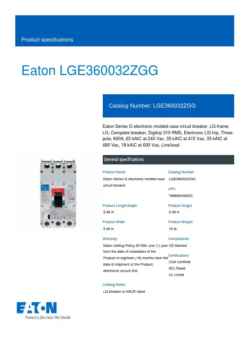
Eaton LGE360032ZGGEaton Series G electronic molded case circuit breaker, LG-frame, LG, Complete breaker, Digitrip 310 RMS, Electronic LSI trip, Three-pole, 600A, 65 kAIC at 240 Vac, 35 kAIC at 415 Vac, 35 kAIC at 480 Vac, 18 kAIC at 600 Vac, Line/loadGeneral specificationsEaton Series G electronic molded case circuit breakerLGE360032ZGG 7866854380235.48 in 5.48 in 5.48 in 16 lb Eaton Selling Policy 25-000, one (1) year from the date of installation of theProduct or eighteen (18) months from thedate of shipment of the Product,whichever occurs first.CE Marked CSA CertifiedIEC RatedUL Listed LG breaker is HACR ratedProduct NameCatalog NumberUPCProduct Length/Depth Product Height Product Width Product Weight WarrantyCompliancesCertificationsCatalog NotesMetric35 kAIC at 415 Vac65 kAIC at 240 Vac35 kAIC at 480 Vac18 kAIC at 600 Vac Complete breakerLGLGComplete breakerLine and load600 Vac600 AElectronic LSIZone selective interlock Three-pole Application of Tap Rules to Molded Case Breaker Terminals Application of Multi-Wire Terminals for Molded Case Circuit BreakersMulti-wire lugs product aidCircuit breaker motor operators product aidCurrent limiting molded case circuit breaker module for series G, JG and CL310+ MCCB product family pocket folderPlug-in adapters for molded case circuit breakers product aid StrandAble terminals product aidMotor protection circuit breakers product aidHigh performance operating handles for Series G circuit breakers product aidMolded case circuit breakers providing higher levels of selective coordination product aidPower metering and monitoring with Modbus RTU product aidSeries G MCCB quick selectorCurrent limiting molded case circuit breaker module product aid Comprehensive circuit protection for control panel applicationsBreaker service centersJ-Frame 310+ and L-Frame 310+ Molded-case circuit breakersEaton's Volume 4—Circuit ProtectionMolded case circuit breakers catalogInstallation Instructions for Series G L-Frame Circuit BreakersMOEM MCCB product selection guideEaton Specification Sheet - LGE360032ZGGNG and ND-Frame molded case circuit breakersL-Frame 310+ Molded-case circuit breakers 100A-600AMounting hardware Interrupt ratingTypeFrameCircuit breaker type Circuit breaker frame type TerminalsVoltage rating Amperage RatingTrip Type CommunicationNumber of poles Application notesBrochuresCatalogsInstallation instructions Specifications and datasheetsEaton Corporation plc Eaton House30 Pembroke Road Dublin 4, Ireland © 2023 Eaton. All Rights Reserved. Eaton is a registered trademark.All other trademarks areproperty of their respectiveowners./socialmedia。
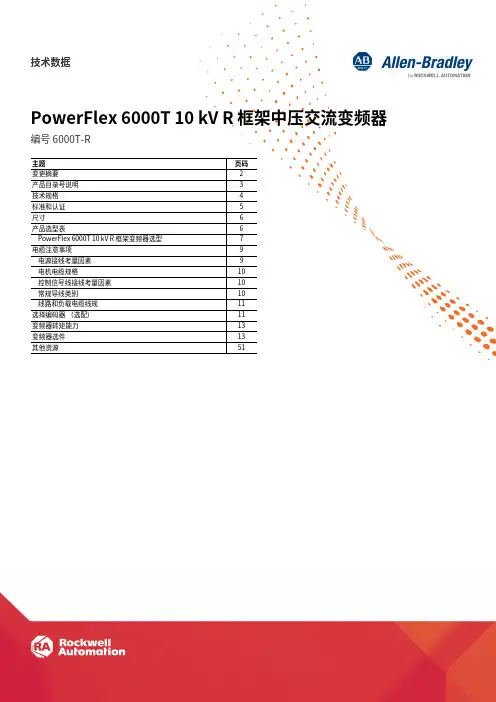
技术数据PowerFlex 6000T 10 kV R 框架中压交流变频器编号 6000T-R主题⻚码变更摘要2产品目录号说明3技术规格4标准和认证5尺寸6产品选型表6PowerFlex 6000T 10 kV R 框架变频器选型7电缆注意事项9电源接线考量因素9电机电缆规格10控制信号线接线考量因素10常规导线类别10线路和负载电缆线规11选择编码器(选配)11变频器转矩能力13变频器选件13其他资源51PowerFlex 6000T 10 kV R 框架中压交流变频器技术数据变更摘要本出版物中包含以下新增内容或更新信息。
该列表仅列出了主要更新,并未反映出所有变更。
主题⻚码更新了概述3更新了变频器规格表:•额定功率范围•输出频率范围•机柜•机械结构涂层5更新了变频器选型表:•PowerFlex 6000T-R 10 kV 50 Hz 变频器 — 标准负载(IEC 认证)•PowerFlex 6000T-R 10 kV 50 Hz 变频器 — 重载(IEC 认证)8 92罗克⻙尔⾃动化出版物 6000-TD101B-ZH-P - 2023 年 2 月罗克⻙尔⾃动化出版物 6000-TD101B-ZH-P - 2023 年 2 月3PowerFlex 6000T 10 kV R 框架中压交流变频器技术数据概述PowerFlex® 中压变频器系列提供多种变频器和选件,可满足您的应用性能需求。
PowerFlex 6000 变频器适合各种应用项目,包括⻛机、泵、压缩机、传送带和铣床。
PowerFlex 6000T-R 10 kV 50 Hz 变频器适用于全新和改装应用项目,为 10 kV 时功率为 280 kW 到 3,550 kW 的电机控制应用项目提供解决方案。
⻛冷式 PowerFlex 6000T 10 kV R 变频器通过实现标准负载与重载应用的软启动和变速控制,最大程度地提高能效。
PowerFlex 6000T-R 10 kV 50 Hz 交流变频器在各种应用项目中都能实现灵活性,可根据电机电压提供多种配置,满足 IEC 和 GB 要求。
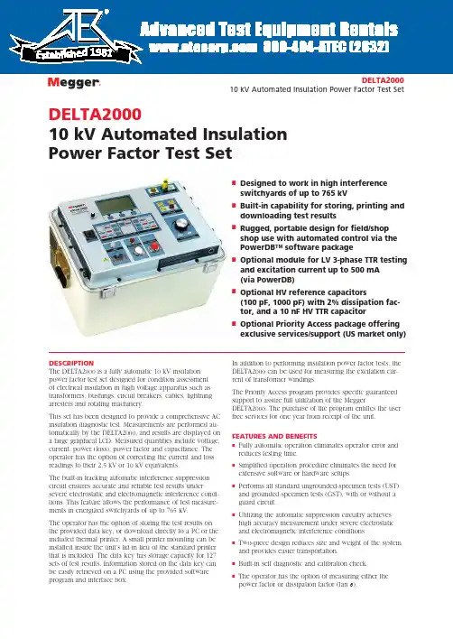
DELTA200010 kV Automated Insulation Power Factor Test SetnDesigned to work in high interference switchyards of up to 765 kVnBuilt-in capability for storing, printing and downloading test resultsnRugged, portable design for field/shop shop use with automated control via the PowerDB™ software packagenOptional module for LV 3-phase TTR testing and excitation current up to 500 mA (via PowerDB)nOptional HV reference capacitors(100 pF, 1000 pF) with 2% dissipation fac-tor, and a 10 nF HV TTR capacitornOptional Priority Access package offering exclusive services/support (US market only)DELTA200010 kV Automated Insulation Power Factor Test SetDESCRIPTIONThe DELTA2000 is a fully automatic 10 kV insulation power factor test set designed for condition assessment of electrical insulation in high voltage apparatus such as transformers, bushings, circuit breakers, cables, lightning arresters and rotating machinery.This set has been designed to provide a comprehensive AC insulation diagnostic test. Measurements are performed au-tomatically by the DELTA2000, and results are displayed on a large graphical LCD. Measured quantities include voltage, current, power (loss), power factor and capacitance. The operator has the option of correcting the current and loss readings to their 2.5 kV or 10 kV equivalents.The built-in tracking automatic interference suppression circuit ensures accurate and reliable test results undersevere electrostatic and electromagnetic interference condi-tions. This feature allows the performance of test measure-ments in energized switchyards of up to 765 kV.The operator has the option of storing the test results on the provided data key, or download directly to a PC or the included thermal printer. A small printer mounting can be installed inside the unit’s lid in lieu of the standard printer that is included. The data key has storage capacity for 127 sets of test results. Information stored on the data key can be easily retrieved on a PC using the provided software program and interface box.In addition to performing insulation power factor tests, the DELTA2000 can be used for measuring the excitation cur-rent of transformer windings.The Priority Access program provides specific guaranteed support to assure full utilization of the MeggerDELTA2000. The purchase of the program entitles the user free services for one year from receipt of the unit. FEATURES AND BENEFITSn Fully automatic operation eliminates operator error and reduces testing time.nSimplified operation procedure eliminates the need for extensive software or hardware setups.nPerforms all standard ungrounded-specimen tests (UST) and grounded-specimen tests (GST), with or without a guard circuit.nUtilizing the automatic suppression circuitry achieves high accuracy measurement under severe electrostatic and electromagnetic interference conditions.nTwo-piece design reduces size and weight of the system and provides easier transportation.n Built-in self diagnostic and calibration check.nThe operator has the option of measuring either the power factor or dissipation factor (tan ∂).1981DELTA2000 10 kV Automated Insulation Power Factor Test Setn Open-ground detector ensures proper grounding before test.n Interlock switches provide operator safety.n High accuracy SF6 gas-filled capacitor as internal refer-ence.n Built-in interface to the optional Resonating Inductor (Cat. No. 670600) to extend the capacitance measuring range to 1.1µF at 10 kV.n Data key stores 127 sets of test results for retrieval and analysis. Stored results can be easily transferred to a PC using the provided interface box.n Optional printer mounting inside unit’s lid instead of standard thermal printer.n Optional HV TTR capacitor (10 nF) in addition to two HV reference capacitors (100 pF and 1000 pF) with a2% dissipation factor.n Optional module to perform LV three-phase transformer turns ratio testing and excitation current up to 500 mA in accordance with Megger TTR300 product specifications (via PowerDB software).n RS-232 serial interface for downloading the test results to a PC. n Includes a battery/line operated printer for a hard copy of the test results which are date and time stamped.n Optional bar code wand and PC software for recording an alphanumeric test identification in the field.n Optional Priority Access package with exclusive services (US market only).n Optional Oil Test Cell for testing insulating fluids upto 10 kV.n Optional Calibration Standard verifies proper operation and accuracy of the test results.n Interfaces with a PowerDB software package that per-forms extensive information processing, data trendingand report generation. The DELTA2000, available in either 120 or 240 V ac/50 or 60 Hz,includes the Control Unit (top) and High Voltage Unit (bottom)Close-up of DELTA2000 panelDELTA200010 kV Automated Insulation Power Factor Test SetData Keys with PC interface box and standard thermal printerSPECIFICATIONSInput120/230 V ±10%, 1φ, 50/60 Hz, 1440 VAOutput0 to 12 kV, continuously adjustable, 200 mA continuous; 310 mA maximum for up to 5 minutes.The power supply capacity can be expanded to 4 Ampsusing the optional Resonating Inductor, catalog number 670600.AccuracyVoltage(RMS) ±(1% of reading + 1 digit)Current(RMS) ±(1% of reading + 1 digit)Capacitance±(0.5% of reading + 2 pF) in UST mode ±(0.5% of reading + 6 pF) in GST mode Power Factor±2% of reading + 0.05% (up to 90%)Dissipation Factor±2% of reading + 0.05% (up to 200%)Watt Loss±(2% of reading + 1mW)Measuring RangesVoltage250 V to 12 kV, 10 V resolution. Minimum recommended voltage is 500 V.Current0 to 5 Amps, 1µA maximum resolution. The measurement can be corrected to either 2.5 kV or 10 kV equivalents.Capacitance1 pF to 1.1 µF, 0.01 pF maximum resolution on low ranges.Power Factor0 to 100%, 0.01% maximum resolution.Dissipation Factor0 to 1000%, 0.01% maximum resolution.Watt Loss0 to 2 kW, actual power, 0 to 100 kW when corrected to 10 kV equivalent. 0.1 mW maximum resolution. The measurement can be corrected to either 2.5 kV or 10 kV equivalents.MeasurementThe following seven test modes are available, using the blue and red measuring leads, and can be selected by the operator:UST: Ground Red, Measure Blue UST: Ground Blue, Measure RedUST: No Ground, Measure to both Red and Blue GST: No GuardGST: Guard Blue, Ground Red GST: Guard Red, Ground BlueGST: Guard Red, and Blue, No Grounding UST: Ungrounded Specimen Testing GST: Grounded Specimen TestingTest FrequencySame as line frequencyInterference Suppression Available Suppression Methods1. Operator selectable automatic forward/reverse measurement averaging.2. Operator selectable automatic tracking interference cancellation. Safety QualificationsThe test set meets the requirements of both the IEC-1010 and the CE mark specifications. The test set also meets the shock and vibration requirements of the ASTM D999.75 standard. EnvironmentTemperatureOperating: 32 to 122° F ( 0 to 50° C), Storage: -58 to +140° F (-50 to +60° C)Relative HumidityOperating: 0 to 90% non-condensing Storage: 0 to 95% non-condensing DimensionsControl Unit16 H x 22 W x 16 D in.(406 H x 559 W x 406 D mm)High Voltage Unit 16 H x 22 W x 16 D in.(406 H x 559 W x 406 D mm)WeightControl Unit: 74 lb (33kg)High Voltage unit: 63 lb (29 kg)Cables: 35 lb (16 kg)The optional Resonating Inductor expands the capacitance range of the DELTA2000OPTIONAL ACCESSORIESThe optional accessory kit, C/N 670501 includes mini bushing tap connec-tors, hot collar straps, temperature/humidity meter, .75” bushing tap con-nector, 1” bushing tap connector, “J” probe bushing tap connector, 3-ft non-insulating shorting leads, 6-ft non-insulatingshorting leadsOptional capacitor kit includes carry case, TTR capacitor (left), and2 reference capacitors (center). Also shown are 2 connectors (right) that will work with the capacitors and are supplied with the DELTA2000 unitDELTA200010 kV Automated Insulation Power Factor Test SetThe optional Oil Test Cell, C/N 670511, is used for testing insulatingfluids up to 10 kVOptional TTR300D module, for LV three-phase TTR testing, installed inside DELTA HV cabinet. (Lid not shown for clarity.) Via PowerDB software, TTRtesting is in accordance with Megger TTR300 product specifications. External laptop is easily placed on top surface of module for added convenience.The optional Calibration Stan-dard traceable to theNIST for quick operating or calibration checks of test set bridges calibrated in watts loss or in dissipation factorOptional bar code wand for re-cording an alphanumeric testidentificationOPTIONAL ACCESSORIES (Continued)PowerDB™ Acceptance & Maintenance Test Data Management SoftwareThe DELTA2000 is controlled and automated by the PowerDB management system, a powerful softwarepackage providing data management for acceptance and maintenance testing jobs. Customer/contract information is quickly sorted and searched. Opening a specific record shows detailed information such as type of service, order date, sales contact, and invoice information. Job informa-tion can be transferred between field-use databases and a master database. Job/Device Productivity Reports aid in bidding future jobs as well as personnel evaluation.Electrical utilities who have invested in sophisticated Com-puterized Maintenance Management Systems (CMMS) can easily link with the PowerDB software because it works with a number of systems.The package also provides test documentation and trend-ing, report generation and a number of other optional add-ons that are described in the Megger PowerDB data sheet available on our website .Data entry and automated control of Megger DELTA2000DELTA200010 kV Automated Insulation Power Factor Test SetDELTA2000 10 kV Automated Insulation Power Factor Test SetUKArchcliffe Road, Dover CT17 9EN EnglandT +44 (0) 1 304 502101 F +44 (0) 1 304 207342 ******************UNITED STATES4271 Bronze WayDallas, TX 75237-1019 USAT 1 800 723 2861 (USA only)T +1 214 333 3201F +1 214 331 7399******************OTHER TECHNICAL SALES OFFICESValley Forge USA, College StationUSA, Sydney AUSTRALIA, TäbySWEDEN, Ontario CANADA, TrappesFRANCE, Oberursel GERMANY, AargauSWITZERLAND, Kingdom of BAHRAIN,Mumbai INDIA, Johannesburg SOUTHAFRICA, and Chonburi THAILANDISO STATEMENTRegistered to ISO 9001:2000 Cert. no. 10006.01DELTA2000_DS_en_V20Megger is a registered trademark。
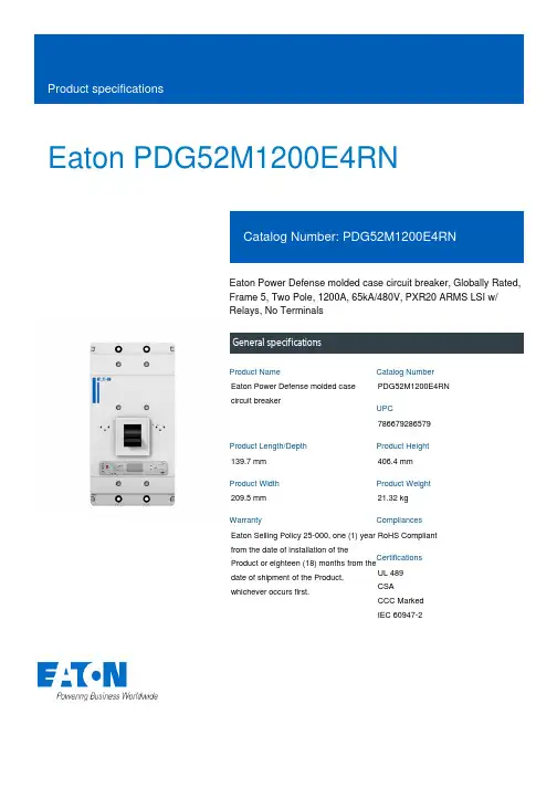
Eaton PDG52M1200E4RNEaton Power Defense molded case circuit breaker, Globally Rated, Frame 5, Two Pole, 1200A, 65kA/480V, PXR20 ARMS LSI w/ Relays, No TerminalsGeneral specificationsEaton Power Defense molded case circuit breakerPDG52M1200E4RN 786679286579139.7 mm 406.4 mm 209.5 mm 21.32 kg Eaton Selling Policy 25-000, one (1) year from the date of installation of theProduct or eighteen (18) months from thedate of shipment of the Product,whichever occurs first.RoHS Compliant UL 489CSACCC MarkedIEC 60947-2Product NameCatalog Number UPCProduct Length/Depth Product Height Product Width Product Weight WarrantyCompliancesCertifications1200 AComplete breaker 5Two-polePD5 Global Class A PXR 20 LSI w/ARMS600 Vac600 VNo Terminals65 kAIC at 480 Vac 100 kAIC Icu/ 100 kAIC Ics/ 220 kAIC Icm @240V (IEC) 15 kAIC Icu/ 7.5 kAIC Ics/ 31.5 kAIC Icm @690V (IEC) 65 kAIC @480/277V (UL) 100 kAIC @240V (UL)70 kAIC Icu/ 53 kAIC Ics/ 154 kAIC Icm @380-415V (IEC) 50 kAIC Icu/ 40 kAIC Ics/ 105 kAIC Icm @440V (IEC) 35 kAIC @600/347V (UL)30 kAIC Icu/ 25 kAIC Ics/ 63 kAIC Icm @525V South Africa (IEC)50 kAIC Icu/ 30 kAIC Ics/ 105 kAIC Icm @480V Brazil (IEC)1200 AEaton Power Defense MCCB PDG52M1200E4RN 3D drawing Power Xpert Protection Manager x64Amperage Rating Circuit breaker frame type Frame Number of poles Circuit breaker type Class Trip TypeVoltage rating Voltage rating - max Terminals Interrupt rating Interrupt rating rangeTrip rating 3D CAD drawing packageApplication notesConsulting application guide - molded case circuit breakersPower Xpert Protection Manager x32BrochuresStrandAble terminals product aidPower Defense brochurePower Defense molded case circuit breaker selection posterPower Defense technical selling bookletCatalogsPower Defense molded case circuit breakers - Frame 5 product aid Power Xpert Release trip units for Power Defense molded case circuit breakersMolded case circuit breakers catalogCertification reportsPDG6 CSA certificationPDG5 CB reportPDG5 CCC certificationPDG5 CSA CertificationPDG6 CCC certificatePower Defense Declaration concerning California’s Proposition 65EU Declaration of Conformity - Power Defense molded case circuit breakersPDG5 UL authorizationInstallation instructionsPower Defense Frame 2/3/4/5/6 voltage neutral sensor module wiring instructions – IL012316ENPower Defense Frame 4_5 flex shaft handle mech assembly instructions - IL012284ENPower Defense Frame 5 aux, alarm, shunt trip and uvr instructions(IL012201EN).pdfPower Defense Frame 5 vertical padlockable handle lock hasp installation instructions - IL012283ENPower Defense Frame 5 key interlock installation instructions -IL012294ENPower Defense Frame 5 walking beam installation instructions -IL012290ENPower Defense Frame 5 breaker status module installation instructions – IL012307ENPower Defense Frame 4_5_6 high performance flex shaft handle mech assembly instructions - IL012296ENInstallation videosPower Defense Frame 5 Trip Unit Replacement Animated Instructions Power Defense Frame 5 UVR Trip How-To VideoPower Defense Frame 5 Aux, Alarm, ST and UVR Animated Instructions.rh1Power Defense Frame 5 Shunt Trip, Aux and Alarm Trip How-To Video Power Defense Frame 5 Trip Unit Upgrade Relays Board, Animated Instructions.rhPower Defense Frame 5 Trip Unit Upgrade Wire Harnesses, Animated Instructions.rhMultimediaPower Defense molded case circuit breakersPower Defense Frame 2 Variable Depth Rotary Handle Mechanism Installation How-To VideoPower Defense Frame 5 Trip Unit How-To VideoEaton Power Defense for superior arc flash safetyPower Defense Frame 6 Trip Unit How-To VideoPower Defense Frame 3 Variable Depth Rotary Handle Mechanism Installation How-To VideoPower Defense BreakersSpecifications and datasheetsEaton Specification Sheet - PDG52M1200E4RNTime/current curvesPower Defense time current curve Frame 5 - PD5White papersMolded case and low-voltage power circuit breaker healthIntelligent power starts with accurate, actionable dataSingle and double break MCCB performance revisited Implementation of arc flash mitigating solutions at industrial manufacturing facilitiesIntelligent circuit protection yields space savingsMaking a better machineSafer by design: arc energy reduction techniquesMolded case and low-voltage breaker healthEaton Corporation plc Eaton House30 Pembroke Road Dublin 4, Ireland © 2023 Eaton. All Rights Reserved. Eaton is a registered trademark.All other trademarks areproperty of their respectiveowners./socialmedia。
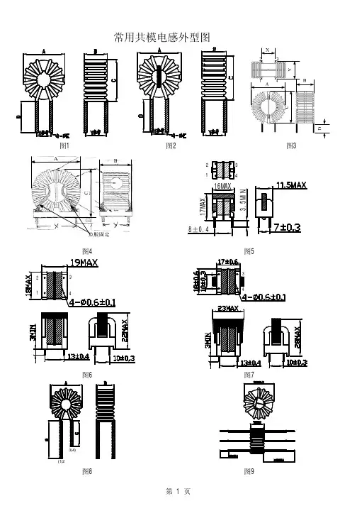
*CMI350uH/1A/H9 1.0350321768VDC 12645图1、2*CMI500uH/1A/H10 1.0500391768VDC 13 6.545图1、2*CMI2.0mH/1A/H14 1.020********VDC 17968图1、2CMI1.5mH/1A/H14 1.01500791768VDC 17968图1、2CMI1.0mH/1A/H14 1.010********VDC 17968图1、2CMI2.0mH/1.5A/H14 1.52000501768VDC 17968图1、2CMI1.5mH/1.5A/H14 1.51500441768VDC 17968图1、2CMI1.0mH/1.5A/H14 1.51000371768VDC 17968图1、2*CMI1.5mH/2A/H14 2.01500441768VDC 17968图1、2CMI1.0mH/2A/H14 2.010********VDC 17968图1、2CMI500uH/3A/H14 3.0500151768VDC 18968图1、2CMI350uH/3A/H14 3.0350131768VDC 18968图1、2CMI240uH/3A/H14 3.024*******VDC 18968图1、2CMI170uH/4A/H14 4.017071768VDC 18968图1、2CMI170uH/5A/H14 5.017061768VDC 19968图1、2CMI6.0mH/1A/H1608 1.060001571768VDC 1912711图1、2CMI4.2mH/1A/H1608 1.042001301768VDC 1912711图1、2CMI3.0mH/1A/H1608 1.030001131768VDC 1912711图1、2CMI4.2mH/1.5A/H1608 1.54200731768VDC 2013711图1、2CMI3.0mH/1.5A/H1608 1.53000641768VDC 2013711图1、2CMI3.0mH/2A/H160808 2.03000541768VDC 1912711图1、2CMI2.0mH/2A/H1608 2.020********VDC 1912711图1、2*CMI1.5mH/3A/H1608 3.01500251768VDC 2013712图1、2CMI1.0mH/3A/H1608 3.010********VDC 2013712图1、2CMI700uH/3A/H1608 3.0700191768VDC 2013712图1、2CMI500uH/4A/H1608 4.0500121768VDC 2013712图1、2CMI350uH/4A/H1608 4.0350101768VDC 2013712图1、2CMI350uH/5A/H1608 5.035091768VDC 2013712图1、2CMI240uH/6A/H1608 6.025061768VDC 2014712图1、2CMI170uH/7A/H16087.017051768VDC 2014712图1、2CMI3.0mH/1A/H1605 1.030001161768VDC 198.578图1、2CMI2.0mH/1A/H1605 1.020********VDC 198.578图1、2CMI3.0mH/1.5A/H1605 1.53000651768VDC 198.578图1、2CMI1.5mH/2A/H1605 2.01500391768VDC 198.578图1、2CMI1.0mH/2A/H1605 2.010********VDC 198.578图1、2CMI700uH/2A/H1605 2.0700281768VDC 198.578图1、2CMI1.0mH/3A/H1605 3.010********VDC 20978图1、2CMI700uH/3A/H1605 3.0700181768VDC 20978图1、2CMI350uH/4A/H1605 4.0350111768VDC 20978图1、2CMI240uH/5A/H1605 5.025071768VDC 201078图1、2CMI3.0mH/2A/H18 2.03000611768VDC 21978.5图1、2CMI2.0mH/2A/H18 2.020********VDC 21978.5图1、2CMI1.5mH/2A/H18 2.01500431768VDC 21978.5图1、2*CMI2.0mH/3A/H18 3.020********VDC 221078.5图1、2CMI1.5mH/3A/H18 3.01500291768VDC 221078.5图1、2*CMI700uH/4A/H18 4.0700151768VDC 2210.578.5图1、2CMI500uH/4A/H184.0500131768VDC221078.5图1、2MAX MAX 参考参考MAX 1mA,5s @1kHz,0.3V 流(A)流(A)MAX MAX参考参考@1kHz,0.3VMAX1mA,5sCMI500uH/5A/H18 5.0500111768VDC231178.5图1、2 CMI350uH/5A/H18 5.035091768VDC231178.5图1、2 CMI350uH/6A/H18 6.035071768VDC231178.5图1、2 CMI7.0mH/2A/H22H 2.07000992000VAC2916912图3 CMI6.0mH/2A/H22H 2.06000912000VAC2916912图3 CMI4.2mH/2A/H22H 2.04200782000VAC2815912图3 CMI6.0mH/3A/H22H 3.06000602000VAC2916912图3 *CMI4.2mH/3A/H22H 3.04200502000VAC2814912图3 CMI3.0mH/3A/H22H 3.03000432000VAC2814912图3 CMI1.5mH/4A/H22H 4.01500242000VAC2914912图3 CMI1.0mH/4A/H22H 4.010********VAC2914912图3 *CMI1.0mH/5A/H22H 5.010********VAC2813912图3 CMI700uH/5A/H22H 5.0700142000VAC2914912图3 CMI700uH/6A/H22H 6.0700112000VAC3014912图3 CMI500uH/7A/H22H7.050082000VAC3014912图3 CMI1.0mH/8A/H22H8.010********VAC3014912图3 CMI700uH/8A/H22H8.070062000VAC3014912图3 CMI20mH/3AY/H25 3.0200001212000VAC322217.515图4 CMI15mH/3AY/H25 3.0150001052000VAC322217.515图4 CMI10mH/3AY/H25 3.010*********VAC322217.515图4 CMI7.0mH/3AY/H25 3.07000722000VAC322217.515图4 CMI10mH/4AY/H25 4.010*********VAC322217.515图4 CMI7.0mH/4AY/H25 4.07000572000VAC322217.515图4 CMI6.0mH/4AY/H25 4.06000522000VAC322217.515图4 CMI4.2mH/4AY/H25 4.04200442000VAC322217.515图4 CMI3.0mH/4AY/H25 4.03000382000VAC322217.515图4 CMI2.0mH/4AY/H25 4.020********VAC322217.515图4 *CMI3.0mH/5AY/H25 5.03000312000VAC322217.515图4 CMI2.0mH/5AY/H25 5.020********VAC332217.515图4 CMI1.5mH/5AY/H25 5.01500222000VAC332217.515图4 CMI2.0mH/6AY/H25 6.020********VAC332217.515图4 CMI1.5mH/6AY/H25 6.01500182000VAC332217.515图4 CMI1.0mH/6AY/H25 6.010********VAC332217.515图4 CMI2.0mH/7AY/H257.020********VAC342317.515图4 CMI1.5mH/7AY/H257.01500162000VAC342317.515图4 CMI1.0mH/7AY/H257.010********VAC342317.515图4 CMI1.5mH/8AY/H258.01500132000VAC342317.515图4 *CMI1.0mH/10AY/H2510.010*******VAC342317.515图4 CMI700uH/10AY/H2510.070072000VAC342317.515图4 *CMI30uH/1A/H8* 1.02027500VDC10433图8 *CMI16mH/1A/W14** 1.0160001742000VAC181068图1、2 *3CMI2.0mH/8A/H318.020********VAC3820---CMI15mH/0.2A/U9.80.21500023302000VAC----图5 CMI10mH/0.2A/U9.80.21000018922000VAC----图5 CMI6.0mH/0.3A/U9.80.360009032000VAC----图5 CMI4.2mH/0.3A/U9.80.342007572000VAC----图5 CMI3.0mH/0.3A/U9.80.330006472000VAC----图5流(A)MAX1mA,5sMAX MAX参考参考@1kHz,0.3VCMI2.0mH/0.3A/U9.80.320005252000VAC----图5 CMI1.5mH/0.3A/U9.80.315004642000VAC----图5 CMI1.0mH/0.3A/U9.80.310003792000VAC----图5 *CMI2.0mH/0.5A/U9.80.520003092000VAC----图5 CMI1.5mH/0.5A/U9.80.515002732000VAC----图5 CMI1.0mH/0.5A/U9.80.510002232000VAC----图5 *CMI500uH/1A/U9.8 1.0500702000VAC----图5 CMI35mH/0.3A/U100.33500021042000VAC----图6 CMI28mH/0.3A/U100.32800018862000VAC----图6 CMI20mH/0.3A/U100.32000015892000VAC----图6 CMI15mH/0.3A/U100.31400013402000VAC----图6 CMI10mH/0.3A/U100.31000011212000VAC----图6 *CMI15mH/0.5A/U100.5140007872000VAC----图6 CMI10mH/0.5A/U100.5100006592000VAC----图6 CMI7.0mH/0.5A/U100.570005582000VAC----图6 *CMI3.0mH/1A/U10 1.030001622000VAC----图6 CMI2.0mH/1A/U10 1.020*********VAC----图6 CMI1.5mH/1A/U10 1.015001182000VAC----图6 CMI1.0mH/2A/U10 2.010********VAC----图6 *CMI4.2mH/2A/U16 2.04200922000VAC----图7 CMI3.0mH/2A/U16 2.03000782000VAC----图7 CMI2.0mH/2A/U16 2.020********VAC----图7 CMI1.5mH/2A/U16 2.01500552000VAC----图7 CMI1.0mH/2A/U16 2.010********VAC----图7 *CMI1.5mH/3A/U16 3.01500312000VAC----图7 CMI1.0mH/3A/U16 3.010********VAC----图7 CMI1.0mH/4A/U16 4.010********VAC----图7说明:此系列器件电流密度取值为6A/mm2,型号后面带*的为镍锌磁芯绕制,带**的为非晶磁芯绕制。

MMSZ4686T1G MMSZ4686T1G.MMSZ4xxxT1G Series, SZMMSZ4xxxT1G Series Zener Voltage Regulators 500 mW, Low I ZT SOD−123 Surface MountThree complete series of Zener diodes are offered in the convenient, surface mount plastic SOD−123 package. These devices provide a convenient alternative to the leadless 34−package style.Features•500 mW Rating on FR−4 or FR−5 Board•Wide Zener Reverse V oltage Range − 1.8 V to 43 V•Low Reverse Current (I ZT) − 50 m A•Package Designed for Optimal Automated Board Assembly •Small Package Size for High Density Applications•ESD Rating of Class 3 (>16 kV) per Human Body Model•SZ Prefix for Automotive and Other Applications Requiring Unique Site and Control Change Requirements; AEC−Q101 Qualified and PPAP Capable•These Devices are Pb−Free and are RoHS Compliant*Mechanical Characteristics:CASE:V oid-free, transfer-molded, thermosetting plastic case FINISH:Corrosion resistant finish, easily solderableMAXIMUM CASE TEMPERATURE FOR SOLDERING PURPOSES: 260°C for 10 SecondsPOLARITY:Cathode indicated by polarity band FLAMMABILITY RATING:UL 94 V−0MAXIMUM RATINGSRating Symbol Max Units Total Power Dissipation on FR−5 Board,(Note 1) @ T L = 75°CDerated above 75°C P D5006.7mWmW/°CThermal Resistance, (Note 2) Junction−to−Ambient R q JA340°C/WThermal Resistance, (Note 2) Junction−to−Lead R q JL150°C/WJunction and Storage Temperature Range T J, T stg−55 to+150°CStresses exceeding those listed in the Maximum Ratings table may damage the device. If any of these limits are exceeded, device functionality should not be assumed, damage may occur and reliability may be affected.1.FR−5 = 3.5 X 1.5 inches, using the minimum recommended footprint.2.Thermal Resistance measurement obtained via infrared Scan Method.*For additional information on our Pb−Free strategy and soldering details, please download the ON Semiconductor Soldering and Mounting Techniques Reference Manual, SOLDERRM/D.Cathode AnodeSee specific marking information in the device marking column of the Electrical Characteristics table on page 3 of this data sheet.DEVICE MARKING INFORMATIONSOD−123CASE 425STYLE 1Device Package Shipping†ORDERING INFORMATIONMARKING DIAGRAM†For information on tape and reel specifications, including part orientation and tape sizes, please refer to our T ape and Reel Packaging Specifications Brochure, BRD8011/D.MMSZ4xxxT1G SOD−123(Pb−Free)3,000 /Tape & ReelMMSZ4xxxT3G SOD−123(Pb−Free)10,000 /Tape & Reel xx= Device Code (Refer to page 3)M= Date CodeG= Pb−Free Package(Note: Microdot may be in either location)1SZMMSZ4xxxT1G SOD−123(Pb−Free)3,000 /Tape & ReelSZMMSZ4xxxT3G SOD−123(Pb−Free)10,000 /Tape & ReelELECTRICAL CHARACTERISTICS (T A = 25°C unless otherwise noted, V F = 0.9 V Max. @ I F = 10 mA)Symbol ParameterV Z Reverse Zener Voltage @ I ZTI ZT Reverse CurrentI R Reverse Leakage Current @ V RVR Reverse VoltageI F Forward CurrentV F Forward Voltage @ I FProduct parametric performance is indicated in the Electrical Characteristics for the listed test conditions, unless otherwise noted. Product performance may not be indicated by the Electrical Characteristics if operated under different conditions.ELECTRICAL CHARACTERISTICS (T A = 25°C unless otherwise noted, V F = 0.9 V Max. @ I F = 10 mA)Device*DeviceMarkingZener Voltage (Note 3)Leakage CurrentV Z (Volts)@ I ZT I R @ V RMin Nom Max m A m A VoltsMMSZ4678T1G CC 1.71 1.8 1.89507.51 MMSZ4679T1G CD 1.90 2.0 2.105051 MMSZ4680T1G CE 2.09 2.2 2.315041 MMSZ4681T1G CF 2.28 2.4 2.525021 MMSZ4682T1G CH 2.565 2.7 2.8355011 MMSZ4683T1G CJ 2.85 3.0 3.15500.81 MMSZ4684T1G CK 3.13 3.3 3.47507.5 1.5 MMSZ4685T1G CM 3.42 3.6 3.78507.52 MMSZ4686T1G CN 3.70 3.9 4.105052 MMSZ4687T1G CP 4.09 4.3 4.525042 SZMMSZ4687T1G CG6 4.09 4.3 4.525042 MMSZ4688T1G CT 4.47 4.7 4.9450103 MMSZ4689T1G CU 4.85 5.1 5.3650103 MMSZ4690T1G/T3G CV 5.32 5.6 5.8850104 MMSZ4691T1G CA 5.89 6.2 6.5150105 MMSZ4692T1G CX 6.46 6.87.145010 5.1 MMSZ4693T1G CY7.137.57.885010 5.7 MMSZ4694T1G CZ7.798.28.61501 6.2 MMSZ4695T1G DC8.278.79.14501 6.6 MMSZ4696T1G DD8.659.19.56501 6.9 MMSZ4697T1G DE9.501010.505017.6 MMSZ4698T1G DF10.451111.55500.058.4 MMSZ4699T1G DH11.401212.60500.059.1 MMSZ4700T1G DJ12.351313.65500.059.8 MMSZ4701T1G DK13.301414.70500.0510.6 MMSZ4702T1G DM14.251515.75500.0511.4 MMSZ4703T1G†DN15.201616.80500.0512.1 MMSZ4704T1G DP16.151717.85500.0512.9 MMSZ4705T1G DT17.101818.90500.0513.6 MMSZ4706T1G DU18.051919.95500.0514.4 MMSZ4707T1G DV19.002021.00500.0115.2 MMSZ4708T1G DA20.902223.10500.0116.7 MMSZ4709T1G DX22.802425.20500.0118.2 MMSZ4710T1G DY23.752526.25500.0119.0 MMSZ4711T1G†EA25.652728.35500.0120.4 MMSZ4712T1G EC26.602829.40500.0121.2 MMSZ4713T1G ED28.503031.50500.0122.8 MMSZ4714T1G EE31.353334.65500.0125.0 MMSZ4715T1G EF34.203637.80500.0127.3 MMSZ4716T1G EH37.053940.95500.0129.6 MMSZ4717T1G EJ40.854345.15500.0132.6 3.Nominal Zener voltage is measured with the device junction in thermal equilibrium at T L = 30°C ±1°C.*Include SZ-prefix devices where applicable.†MMSZ4703 and MMSZ4711 Not Available in 10,000/Tape & ReelTYPICAL CHARACTERISTICSV Z , T E M P E R A T U R E C O E F F I C I E N T (m V /C )°θV Z , NOMINAL ZENER VOLTAGE (V)Figure 1. Temperature Coefficients (Temperature Range −55°C to +150°C)V Z , T E M P E R A T U R E C O E F F I C I E N T (m V /C )°θ100101V Z , NOMINAL ZENER VOLTAGE (V)Figure 2. Temperature Coefficients (Temperature Range −55°C to +150°C)1.21.00.80.60.40.20T, TEMPERATURE (5C)Figure 3. Steady State Power Derating P p k, P E A K S U R G E P O W E R (W A T T S )PW, PULSE WIDTH (ms)Figure 4. Maximum Nonrepetitive Surge PowerP D , P O W E R D I S S I P A T I O N (W A T T S )V Z , NOMINAL ZENER VOLTAGEFigure 5. Effect of Zener Voltage onZener ImpedanceZ Z T , D Y N A M I C I M P E D A N C E ()ΩTYPICAL CHARACTERISTICSC , C A P A C I T A N C E (p F )V Z , NOMINAL ZENER VOLTAGE (V)Figure 6. Typical Capacitance 1000100101V Z , ZENER VOLTAGE (V)1001010.10.01I Z , Z EN E R C U R R E N T (m A )V Z , ZENER VOLTAGE (V)1001010.10.01I R , L E A K A G E C U R R E N T (A )μV Z , NOMINAL ZENER VOLTAGE (V)Figure 7. Typical Leakage Current10001001010.10.010.0010.00010.00001I Z , Z E N E R C U R R E N T (m A )Figure 8. Zener Voltage versus Zener Current(V Z Up to 12 V)Figure 9. Zener Voltage versus Zener Current(12 V to 91 V)SOD−123CASE 425−04ISSUE GDATE 07 OCT 2009SCALE 5:1NOTES:1.DIMENSIONING AND TOLERANCING PER ANSIY14.5M, 1982.2.CONTROLLING DIMENSION: INCH.DIM MIN NOM MAXMILLIMETERSINCHESA0.94 1.17 1.350.037A10.000.050.100.000b0.510.610.710.020c1.600.150.055D 1.40 1.80E 2.54 2.69 2.840.100---3.680.140L0.253.860.0100.0460.0020.0240.0630.1060.1450.0530.0040.0280.0710.1120.152MIN NOM MAX3.56H E---------0.006------------GENERICMARKING DIAGRAM**For additional information on our Pb−Free strategy and solderingdetails, please download the ON Semiconductor Soldering andMounting Techniques Reference Manual, SOLDERRM/D.SOLDERING FOOTPRINT**This information is generic. Please refer to device datasheet for actual part marking. Pb−Free indicator, “G” ormicrodot “ G”, may or may not be present.XXX= Specific Device CodeM= Date CodeG= Pb−Free Package1STYLE 1:PIN 1. CATHODE2. ANODE0.910.036ǒmminchesǓSCALE 10:1------q001010°°°°(Note: Microdot may be in either location) MECHANICAL CASE OUTLINEPACKAGE DIMENSIONSON Semiconductor and are trademarks of Semiconductor Components Industries, LLC dba ON Semiconductor or its subsidiaries in the United States and/or other countries.ON Semiconductor reserves the right to make changes without further notice to any products herein. ON Semiconductor makes no warranty, representation or guarantee regarding the suitability of its products for any particular purpose, nor does ON Semiconductor assume any liability arising out of the application or use of any product or circuit, and specifically disclaims any and all liability, including without limitation special, consequential or incidental damages. ON Semiconductor does not convey any license under its patent rights nor theON Semiconductor and are trademarks of Semiconductor Components Industries, LLC dba ON Semiconductor or its subsidiaries in the United States and/or other countries.ON Semiconductor owns the rights to a number of patents, trademarks, copyrights, trade secrets, and other intellectual property. A listing of ON Semiconductor’s product/patent coverage may be accessed at ON Semiconductor makes no warranty, representation or guarantee regarding the suitability of its products for any particular purpose, nor does ON Semiconductor assume any liability arising out of the application or use of any product or circuit, and specifically disclaims any and all liability, including without limitation special, consequential or incidental damages.PUBLICATION ORDERING INFORMATIONTECHNICAL SUPPORTNorth American Technical Support:Voice Mail: 1 800−282−9855 Toll Free USA/Canada Phone: 011 421 33 790 2910LITERATURE FULFILLMENT :Email Requests to:*******************ON Semiconductor Website: Europe, Middle East and Africa Technical Support:Phone: 00421 33 790 2910For additional information, please contact your local Sales RepresentativeMMSZ4686T1G MMSZ4686T1G.。
emc 共模电感
(最新版)
目录
1.共模电感的定义和作用
2.共模电感的特点
3.共模电感的应用领域
4.共模电感的优势
正文
共模电感,也被称为共模扼流圈,是一种电子元件,常用于电脑的开关电源中过滤共模的电磁干扰信号。
在板卡设计中,共模电感起到 EMI 滤波的作用,用于抑制高速信号线产生的电磁波向外辐射发射。
共模电感具有以下特点:
1.在大的频率范围内有良好的衰减性能
2.漏感低,具有更好的性能稳定性
3.电感量偏差小
4.体积小,较少匝数可获得
由于这些特点,共模电感广泛应用于变频空调、平板电视、电动汽车、逆变焊机、高频电感加热、光伏、风电等领域。
共模电感的优势在于其能够有效地过滤共模电磁干扰信号,从而提高电子设备的稳定性和可靠性。
另外,其体积小、漏感低、电感量偏差小等特点也使得共模电感在实际应用中具有更高的灵活性和便捷性。
第1页共1页。

共模电感10mh共模电感是一种常见的电子元件,用于抑制共模干扰。
在本文中,我们将深入探讨共模电感的原理、应用以及选择注意事项。
一、共模电感的原理共模电感是一种特殊的电感,它具有两个同向绕组,分别与电源和负载相连。
共模电感的作用是抑制共模信号,即同时存在于两个绕组中的信号。
当两个绕组中的信号相同且同向时,共模电感将具有较高的自感感应,从而形成一个高阻抗元件,阻碍共模信号的流动。
而当绕组中的信号不同或方向相反时,共模电感将形成一个低阻抗元件,允许差模信号通过。
二、共模电感的应用共模电感主要应用于电子设备中的信号处理和通信电路中,用于抑制共模干扰。
共模干扰是指在信号传输过程中,由于传输线路的不平衡或其他干扰源的影响,导致信号中同时存在差模信号和共模信号。
共模电感的一个典型应用是在音频放大器电路中使用,它可以抑制电源噪声和其他干扰信号对音频信号的影响,提高音频信号的质量和清晰度。
共模电感还广泛应用于通信电路中的滤波器设计,用于滤除传输线上的共模噪声,提高通信系统的抗干扰能力和信号质量。
三、共模电感的选择注意事项在选择共模电感时,我们需要考虑以下几个因素:1. 电感值:共模电感的电感值决定了其对共模信号的抑制能力。
一般来说,电感值越大,抑制能力越强。
因此,在实际应用中,我们需要根据具体的需求来选择合适的电感值。
2. 电流承载能力:共模电感在工作过程中需要承受一定的电流。
因此,我们需要确保选择的共模电感具有足够的电流承载能力,以免因电流过大而损坏元件。
3. 频率特性:共模电感的频率特性决定了其在不同频段内的抑制效果。
因此,在选择共模电感时,我们需要根据实际应用中的频率范围来选择合适的元件。
4. 尺寸和封装形式:共模电感的尺寸和封装形式对于电路设计和布局具有重要影响。
因此,在选择共模电感时,我们需要考虑其尺寸和封装形式是否适合我们的设计要求。
总结:共模电感是一种用于抑制共模干扰的重要元件,广泛应用于电子设备和通信电路中。
大电流贴片共模电感摘要:一、大电流贴片共模电感的定义和作用二、大电流贴片共模电感的特点三、大电流贴片共模电感的应用领域四、大电流贴片共模电感的选购和替换正文:大电流贴片共模电感,是一种具有高电流处理能力的电感元器件,主要应用于电子设备中,以消除电路中的共模干扰。
它具有体积小、重量轻、功率大等特点,在射频噪声频率范围内具有高阻抗,能有效消除传输线中的电磁干扰。
大电流贴片共模电感的特点主要表现在以下几个方面:1.高电流处理能力:大电流贴片共模电感具有较高的额定电流,能够承受较大的电流冲击。
2.小型化和轻量化:采用贴片式设计,使得电感体积更小,重量更轻,便于在有限的空间内安装和使用。
3.高频特性优越:在射频噪声频率范围内具有高阻抗,能有效消除传输线中的电磁干扰。
4.良好的磁屏蔽结构:闭合磁路结构使得电感具有较好的磁屏蔽效果,降低直接和间接干扰。
大电流贴片共模电感的应用领域广泛,主要应用于电源、通信、汽车电子、工业控制等领域。
在电源系统中,大电流贴片共模电感可用于滤除电源线上的干扰;在通信系统中,可用于消除信号传输过程中的共模干扰;在汽车电子和工业控制领域,可有效降低电磁干扰,提高设备运行稳定性。
在选购和替换大电流贴片共模电感时,需注意以下几点:1.选择合适的电感值和额定电流:根据实际电路需求,选择合适的电感值和额定电流,以保证电感在正常工作范围内。
2.考虑电感的频率特性:不同类型的电感具有不同的频率特性,应根据电路的工作频率选择合适的电感材料。
3.关注电感的品质和可靠性:选购时应关注电感的品质和可靠性,确保在实际应用中能够稳定工作。
在替换时,要注意电感的大小、形状和引脚位置等,确保能顺利安装到电路板上。
广州共模电感参数一、介绍共模电感是一种用于抑制电磁干扰的元件,它可以有效地过滤掉信号中的共模干扰。
广州共模电感作为一种常见的元器件,在电子工程中应用广泛。
本文将重点介绍广州共模电感的参数。
二、参数1. 电感值广州共模电感的电感值是指在直流条件下,该元件对交流信号阻抗的大小。
通常用亨利(H)作为单位表示,常见的规格有10uH、22uH、33uH等。
2. 额定电流额定电流是指在规定条件下,该元件能够承受的最大直流或交流有效值。
广州共模电感通常以毫安(mA)为单位表示,例如100mA、200mA等。
3. 直流内阻直流内阻是指在直流条件下,该元件所具有的内部阻力大小。
它会影响元件对交流信号的阻抗大小和品质因数。
广州共模电感通常以欧姆(Ω)为单位表示。
4. 品质因数品质因数是指在特定频率下,该元件所具有的能量损耗与储存能量之间的比值。
品质因数越高,说明元件损耗的能量越少,性能越好。
广州共模电感的品质因数通常在30~80之间。
5. 电感漏感电感漏感是指在共模电流作用下,该元件所具有的磁场对外界环境的影响程度。
它会影响元件对信号的传输效果和抑制能力。
广州共模电感的漏感通常在0.1~0.5之间。
6. 工作温度范围工作温度范围是指该元件能够正常工作的环境温度范围。
广州共模电感通常在-40℃~+85℃之间。
三、应用广州共模电感主要应用于各种电子设备中,如计算机、通讯设备、音频设备等。
它可以有效地抑制信号中的共模干扰,提高信号传输质量和稳定性。
四、结论综上所述,广州共模电感是一种重要的元器件,在各种电子设备中得到了广泛应用。
了解其参数对于正确选型和使用具有重要意义。