mgp气缸(SMC带导杆)
- 格式:pdf
- 大小:1.79 MB
- 文档页数:5

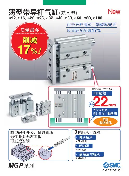
基本型、缓冲型、带锁型带导杆气缸的规格尺寸图
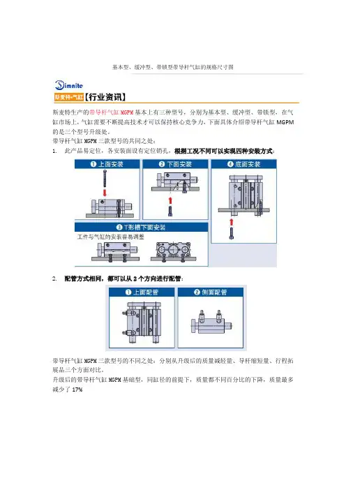
斯麦特生产的带导杆气缸MGPM基本上有三种型号,分别为基本型、缓冲型、带锁型,在气缸市场上,气缸需要不断提高技术才可以保持核心竞争力,下面具体介绍带导杆气缸MGPM 的是三个型号升级处。
带导杆气缸MGPM三款型号的共同之处:
1. 此产品易定位,各安装面设有定位销孔,根据工况不同可以实现四种安装方式:
2. 配管方式相同,都可以从2个方向进行配管:
带导杆气缸MGPM三款型号的不同之处:分别从升级后的质量减轻量、导杆缩短量、行程拓展品三个方面对比。
升级后的带导杆气缸MGPM基础型,同缸径的前提下,质量都不同百分比的下降,质量最多减少了17%
升级后的带导杆气缸MGPM基础型,突出导杆长度都有小幅度的减少:
带导杆气缸MGPM基础型行程拓展品:
升级后的带导杆气缸MGPM带气缓冲型:
质量最多减轻24%:
导杆最多缩短35.5mm:
MGPM带气缓冲型行程拓展品:
升级后的带导杆气缸MGPM带端锁:
产品特点:及时切断气源,气缸仍能保持在原来位置。
带导杆气缸MGPM带端锁拓展品:
以上内容是带导杆气缸MGPM基本型、缓冲型、带锁型区别的介绍,如您对此问题还想有进一步的了解,或有其他技术咨询以及选型方面的问题,无锡斯麦特具备成熟的技术团队、完善的售前售后服务,随时欢迎您的咨询.。
导杆气缸产品结构导杆气缸是一种常见的机电一体化元件,通常用于机械加工中的行程控制、力的传递以及位置锁定等方面。
下面是导杆气缸产品结构的详细介绍。
导杆气缸主要由以下部分组成:气缸体、活塞、导杆、前端盖、后端盖、尘盖、密封件、端头、固定座等部分,具体结构如下:1.气缸体:气缸体是导杆气缸的主要承载部分,其内壁光洁度高且表面处理均匀,能够使气体在内部流动时更加平稳,同时表面光滑且硬度高,能够更好地抵御环境影响和气压,从而保证了导杆气缸的正常运行。
2.活塞:活塞是导杆气缸的核心部分,通常由铝合金、不锈钢等材料制成,其活动范围为气缸体内部。
活塞通常由密封环、反向开关、导向器及连接杆件等组成,其作用是支撑导杆气缸内气压,从而推动活塞进行运动,并将气密性保持的更好。
3.导杆:导杆是导杆气缸的连接承载部分,用来控制活塞的移动方向,同时优化导向,并使得活塞在滑动过程中更为稳定和均匀。
导杆主要由硬质铬钢或不锈钢等材料制成。
4.前端盖和后端盖:前端盖和后端盖是导杆气缸的固定端部分,主要用于连接导杆,同时还起到防止气缸内的污物和灰尘进入气缸、导杆气缸内外环境隔离的作用。
5.密封件:密封件是导杆气缸内的关键配件,主要是起到密封气体的作用,同样也能有效防止外部污物和灰尘进入气缸内部,导致机器运行不畅甚至损坏。
6.尘盖:尘盖是为了更好地防止外部物体、灰尘等进入气缸内部而设置的一个部件。
在气缸体内、活塞和导杆周围,均会设有一个尘盖,从而保证导杆气缸的正常工作。
7.端头:端头通常固定在导杆上,起到连接气缸和导杆的作用,能够实现气体的顺畅流通,同时可进行角度调整,使导杆运行更为平稳。
8.固定座:固定座是导杆气缸的固定部分,能够使它在安装过程中固定好位置,更为方便地进行安装、调整和维护,同时能够增强气缸的稳定性和可靠性。
二、导杆气缸的工作原理导杆气缸的工作原理主要是利用压缩空气做为介质,来推动活塞完成移动工作。
当气缸内变换压力时,气缸会将空气压缩,并将这一压力传递到活塞表面,从而推动它向前移动。
![Best Pneumatics MGP M 32 周期杆长度[mm] 参考标准杆长在页47说明书](https://uimg.taocdn.com/7c16adc685868762caaedd3383c4bb4cf7ecb7ef.webp)
How to OrderRefer to Standard Strokes on page 47.Compact Guide Cylinder/With End Lock Series MGPø20, ø25, ø32, ø40, ø50, ø63, ø80, ø100For details, refer to p age 47.refer to the table below.*: Solid state auto switches marked with “p ” are produced upon receipt of order.*: Bore sizes 32 to 100 are available for D-P4DW m .*: Bore sizes 25 to 100 are available for D-P3DWA m .*: Lead wire length symbols: 0.5 m·········· N il(Example) M9NW 1 m·········· M (Example) M9NWM 3 m·········· L (Example) M9NWL 5 m·········· Z(Example) M9NWZ*: Since there are other applicable auto switches than listed above, refer to page 66 for details.*: F or details about auto switches with pre-wired connector, refer to the WEB catalog or the Best Pneumatics No. 3. For D-P3DWA m , refer to the WEB catalog .*: Auto switches are shipped together, (but not assembled).*1: W ater resistant type auto switches can be mounted on the above models, but in such case SMC cannot guarantee water resistance.Please consult with SMC regarding water resistant types with the above model numbers.*2: 1 m type lead wire is only applicable to the D-A93.46C o u r t e s y o f C M A /F l o d y n e /H y d r a d y n e ▪ M o t i o n C o n t r o l ▪ H y d r a u l i c ▪ P n e u m a t i c ▪ E l e c t r i c a l ▪ M e c h a n i c a l ▪ (800) 426-5480 ▪ w w w .c m a f h .c o mSymbolRubber bumperSpecificationsStandard StrokesManufacture of Intermediate StrokeLock SpecificationsMade to Order(For details, refer to pages 72 and 89.)*1: 0.1 MPa except the lock unit.*2: M aximum speed with no load. Depending on the operating conditions, the piston speed may not besatisfied. Make a model selection, considering a load according to the graph on pages 16 to 22.Adjust switch positions for operation at both the stroke end and backlash (2 mm) movement positions.Lock position Head end, Rod end Holding force (Max.) N ø20ø25ø32ø40ø50ø63ø80ø1002153305508601340214034505390Backlash 2 mm or less Manual releaseNon-lock type, Lock type*: The minimum stroke for mounting auto switches is 10 stroke or more for two switches, and 5 stroke or more for one switch.*: Intermediate stroke (in 1 mm increments) based on an exclusive body will be available upon request for special.DescriptionSpacer installation type.Dealing with the stroke in 5 mm increments is available by installing spacer with standard stroke cylinder. When a spacer is mounted on the cylinder with an end lock on the rod side, use a special piston rod.Part no.Refer to “How to Order” for the standard model numbers on page 46.Applicable stroke [mm] 5 to 395ExamplePart no.: MGPM50-35-HNA spacer 15 mm in width is installed in a MGPM50-50-HN. C dimension is 119 mm.Theoretical Output*1: The shape is the same as the current product.47Series MGPC o u r t e s y o f C M A /F l o d y n e /H y d r a d y n e ▪ M o t i o n C o n t r o l ▪ H y d r a u l i c ▪ P n e u m a t i c ▪ E l e c t r i c a l ▪ M e c h a n i c a l ▪ (800) 426-5480 ▪ w w w .c m a f h .c o mθModel selection is the same as MGP/standard type.Refer to pages 16 to 23.Model selection Allowable Rotational Torque of Plate.Non-rotating Accuracyof PlateCalculation: (Example) MGPM50-100-HN• B asic Weight + Lock unit additional weight• 5.74 + 0.24 = 5.98 k gFor non-rotating accuracy q without load, usea value no more than the values in the table asa guide.48 CourtesyofCMA/Flodyne/Hydradyne▪MotionControl▪Hydraulic▪Pneumatic▪Electrical▪Mechanical▪(8ø50 or moreø20, ø25: 25 stroke(Rod end lock)ø20 to ø63øø80, ø100ø63 or moreNon-locking type(Head end lock)bore size.*: S ince the seal kit does not include a grease pack, order it separately.Grease pack part no.: GR-S-010 (10 g) Construction/Series MGPM49Series MGPCourtesyofCMA/Flodyne/Hydradyne▪MotionControl▪Hydraulic▪Pneumatic▪Electrical▪Mechanical▪(8)426-548▪www.cmafh.comø63 or moreLock type50C o u r t e s y o f C M A /F l o d y n e /H y d r a d y n e ▪ M o t i o n C o n t r o l ▪ H y d r a u l i c ▪ P n e u m a t i c ▪ E l e c t r i c a l ▪ M e c h aDetailed figure ofsection XXEnd lock mechanism(Manual release lock type)ø25With rod end lockWith head end lockDimensions: ø20, ø25MGPL (Ball bushing),End Lock Mechanism*: For intermediate strokes other than standard strokes, refer to the Manufacture of Intermediate Stroke on page 47.*: Rc, NPT and G ports can be selected. (Refer to page 46.)T-slot dimensions51Series MGPCourtesyofCMA/Flodyne/Hydradyne▪MotionControl▪Hydraulic▪Pneumatic▪Electrical▪Mechanical▪(8)426-548▪www.cmafh.comDetailed figure of section XXEnd lock mechanism(Manual release lock type) With rod end lockWith head end lock*: For intermediate strokes other than standard strokes, refer to the Manufacture of Intermediate Stroke on page 47.*: Rc, NPT and G ports can be selected. (Refer to page 46.)52 CourtesyofCMA/Flodyne/Hydradyne▪MotionControl▪Hydraulic▪Pneumatic▪Electrical▪Mechanical▪(8)426-548▪www.cmDetailed figure of section XXEnd lock mechanism(Manual release lock type) With rod end lockWith head end lock*: For intermediate strokes other than standard strokes, refer to the Manufacture of Intermediate Stroke on page 47.*: Rc, NPT and G ports can be selected. (Refer to page 46.)Dimensions: ø80, ø100MGPL (Ball bushing),End Lock Mechanism53Series MGPCourtesyofCMA/Flodyne/Hydradyne▪MotionControl▪Hydraulic▪Pneumatic▪Electrical▪Mechanical▪(8)426-548▪www.cmafh.comLockReleaseReleasedLockedWith head end lockSeries MGP With End LockSpecific Product PrecautionsBe sure to read this before handling. Refer to the back cover for Safety Instructions.For Actuator and Auto Switch Precautions, refer to Handling Precautions for SMCProducts and the Operation Manual on the SMC website, Use Recommended Air Pressure Circuit.Caution• It is necessary for proper locking and unlocking.Operating PressureCaution1. Supply air pressure of 0.15 MPa or higher to the port on the sidethat has the lock mechanism, as it is necessary for disengagingthe lock.Exhaust Air SpeedCaution1. The lock will engage automatically if the air pressure at the port onthe side that has the lock mechanism becomes 0.05 MPa or less.Be aware that if the piping on the side that has the lock mechanismis narrow and long, or if the speed controller is located far from thecylinder port, the exhaust air speed could become slower, involvinga longer time for the lock to engage. A similar result will ensure ifthe silencer that is installed on the exhaust port of the solenoidvalve becomes clogged.Lock DisengagementWarning1. To disengage the lock, make sure to supply air pressure to theport on the side without a lock mechanism, thus preventing theload from being applied to the lock mechanism. (Refer to therecommended air pressure circuit.) If the lock is disengaged whenthe port on the side that does not contain a lock mechanism is inthe exhausted state and the load is being applied to the lockmechanism, undue force will be applied to the lock mechanism,and it may damage the lock mechanism. Also, it could beextremely dangerous, because the piston rod could movesuddenly.HandlingCaution1. Do not use a 3 position solenoid valve.Avoid using this cylinder in combination with a 3 position solenoidvalve (particularly the closed center metal seal type). If air pressurebecomes sealed inside the port on the side that contains the lockmechanism, the lock will not engage. Even if the lock is engagedat first, the air that leaks from the solenoid valve could enter thecylinder and cause the lock to disengage as time elapses.2. Back pressure is necessary for unlocking.Before starting, make sure that air is supplied to the side that is notequipped with a lock mechanism as shown in the diagram above.Otherwise, the lock may not disengage.(Refer to “Rock Disengagement”.)3. Disengage the lock before installing oradjusting the cylinder.The lock could become damaged if the cylinder is installed with itslock engaged.4. Operate the cylinder at a load ratio of 50% or less.The lock might not disengage or might become damaged if a loadratio of 50% is exceeded.5. Do not synchronize multiple cylinders.Do not operate two or more end lock cylinders synchronized tomove a single workpiece because one of the cylinder locks maynot be able to disengage when required.6. Operate the speed controller under meter-out control.If operated under meter-in control, the lock might not disengage.7. On the side that has a lock, make sure tooperate at the stroke end of the cylinder.The lock might not engage or disengage if the piston of thecylinder has not reached the stroke end.8. Do not use the air cylinder as an air-hydrocylinder. This may result in oil leak.9. The position adjustment of the auto switchshould be performed at two positions; a po-sition determined by the stroke and a posi-tion after the backlash movement (by 2 mm).When a 2-color indication auto switch is adjusted to show green atthe stroke end, the indication may turn red when the cylinderreturns by the backlash. This, however, is not an error.1. Non-locking style manual releaseInsert the bolt, which is provided as anaccessory part, through the rubber cap (it isnot necessary to remove the rubber cap).Screw the bolt into the lock piston and pullthe bolt to disengage the lock. Releasingthe bolt will re-engage the lock.otherwise it may cause malfunction of the locking feature.Manual DisengagementCaution2. Locking style manual releaseTurn 90°counterclockwise while pushing the M/O knob. Lock isreleased when on the cap and OFF mark on the M/O knobcorrespond. (Lock remains released.)When locking isdesired, turn 90°clockwise while fullypushing the M/O knoband correspond onthe cap and ONmark on the M/O knob.Confirm the correctposition by click sound“click”. Otherwise, lockmay not be engaged.54 CourtesyofCMA/Flodyne/Hydradyne▪MotionControl▪Hydraulic▪Pneumatic▪Electrical▪Mechanical▪(8)426-548▪www.cmafh.com。
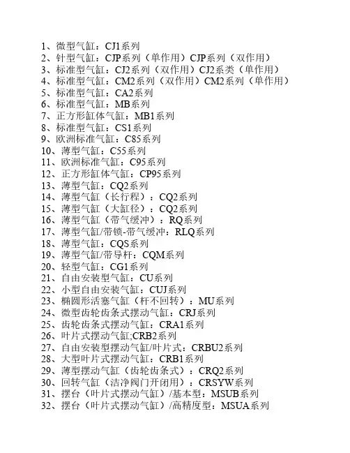
10种常用SMC气缸的类型、特点、用途10种常用SMC气缸的类型、特点、用途SMC气缸动中将压缩气体的压力能转换为机械能的气动执行元件。
汽缸有作往复直线运动的和作往复摆动的两类。
作往复直线运动的汽缸又可分为单作用、双作用、膜片式和冲击汽缸4种。
①SMC气缸仅一端有活塞杆,从活塞一侧供气聚能产生气压,气压推动活塞产生推力伸出,靠弹簧或自重返回。
②SMC气缸从活塞两侧交替供气,在一个或两个方向输出力。
③SMC气缸用膜片代替活塞,只在一个方向输出力,用弹簧复位。
它的密封性能好,但行程短。
④SMC气缸这是一种新型元件。
它把压缩气体的压力能转换为活塞高速(1020米/秒)运动的动能,借以作功。
冲击汽缸增加了带有喷口和泄流口的中盖。
中盖和活塞把汽缸分成储气腔、头腔和尾腔三室。
它广泛用于下料、冲孔、破碎和成型等多种作业。
作往复摆动的汽缸称摆动汽缸,由叶片将内腔分隔为二,向两腔交替供气,输出轴作摆动运动,摆动角小于280°。
此外,还有回转气缸、气液阻尼缸和步进汽缸等。
工作原理一般来说,同等排量情况下,气门越多,进排气效率越好,就像一个人跑步,累得气喘吁吁时,需要张大嘴巴呼吸。
传统的发动机多是每缸一个进气门和一个排气门,这种二气门配气机构相对比较简单,制造成本低,维修起来也相对容易。
对于输出功率要求不太高的普通发动机来说,两气门就能获得较为满意的发动机输出功率与扭矩性能。
排量较大、功率较大的发动机要采用多气门技术。
的多气门技术是三气门结构,即在一进一排的二气门结构基础上再加上一个进气门。
近年来,世界各大汽车公司新开发的轿车大多采用四气门结构。
四气门配气机构中,每个汽缸各有两个进气门和两个排气门。
四气门结构能大幅度提高发动机的吸气、排气效率。
达到或超过六气门不仅使配气结构过于复杂,还会导致发动机寿命缩短,气门开启的空间帘区(气门的圆周和气门的升程)也较小,效率下降。
因此,四气门技术目前使用最为普遍(一).SMC气缸的作用SMC气缸是机械设备中常用的动力原件,它是将压缩空气的压力能转换成机械能,驱动机构实现往复直线运动、摆动或回转运动。
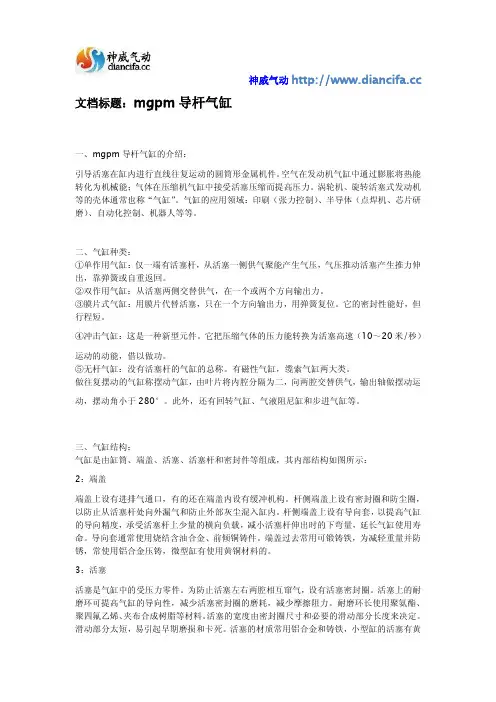
神威气动 文档标题:mgpm导杆气缸一、mgpm导杆气缸的介绍:引导活塞在缸内进行直线往复运动的圆筒形金属机件。
空气在发动机气缸中通过膨胀将热能转化为机械能;气体在压缩机气缸中接受活塞压缩而提高压力。
涡轮机、旋转活塞式发动机等的壳体通常也称“气缸”。
气缸的应用领域:印刷(张力控制)、半导体(点焊机、芯片研磨)、自动化控制、机器人等等。
二、气缸种类:①单作用气缸:仅一端有活塞杆,从活塞一侧供气聚能产生气压,气压推动活塞产生推力伸出,靠弹簧或自重返回。
②双作用气缸:从活塞两侧交替供气,在一个或两个方向输出力。
③膜片式气缸:用膜片代替活塞,只在一个方向输出力,用弹簧复位。
它的密封性能好,但行程短。
④冲击气缸:这是一种新型元件。
它把压缩气体的压力能转换为活塞高速(10~20米/秒)运动的动能,借以做功。
⑤无杆气缸:没有活塞杆的气缸的总称。
有磁性气缸,缆索气缸两大类。
做往复摆动的气缸称摆动气缸,由叶片将内腔分隔为二,向两腔交替供气,输出轴做摆动运动,摆动角小于280°。
此外,还有回转气缸、气液阻尼缸和步进气缸等。
三、气缸结构:气缸是由缸筒、端盖、活塞、活塞杆和密封件等组成,其内部结构如图所示:2:端盖端盖上设有进排气通口,有的还在端盖内设有缓冲机构。
杆侧端盖上设有密封圈和防尘圈,以防止从活塞杆处向外漏气和防止外部灰尘混入缸内。
杆侧端盖上设有导向套,以提高气缸的导向精度,承受活塞杆上少量的横向负载,减小活塞杆伸出时的下弯量,延长气缸使用寿命。
导向套通常使用烧结含油合金、前倾铜铸件。
端盖过去常用可锻铸铁,为减轻重量并防锈,常使用铝合金压铸,微型缸有使用黄铜材料的。
3:活塞活塞是气缸中的受压力零件。
为防止活塞左右两腔相互窜气,设有活塞密封圈。
活塞上的耐磨环可提高气缸的导向性,减少活塞密封圈的磨耗,减少摩擦阻力。
耐磨环长使用聚氨酯、聚四氟乙烯、夹布合成树脂等材料。
活塞的宽度由密封圈尺寸和必要的滑动部分长度来决定。

smc标准气缸SMC标准气缸。
SMC标准气缸是一种常用的气动执行元件,广泛应用于工业自动化领域。
它具有结构简单、性能可靠、使用寿命长的特点,适用于各种机械设备的传动和控制。
本文将从SMC标准气缸的工作原理、结构特点、应用范围等方面进行介绍。
首先,让我们来了解一下SMC标准气缸的工作原理。
SMC标准气缸是利用气体压力来产生直线运动的装置。
当气缸内充入压缩空气时,气缸内活塞受到气压作用而产生推力,从而驱动负载实现直线运动。
当气缸排气时,气缸内的压力降低,活塞受到外部负载的作用而产生回位运动。
这种通过气压来驱动活塞的工作原理,使得SMC标准气缸在自动化控制系统中具有重要的作用。
其次,我们来看一下SMC标准气缸的结构特点。
SMC标准气缸通常由气缸筒、活塞、密封件、导向件、活塞杆等部件组成。
气缸筒是气缸的主体部分,通常由铝合金或不锈钢制成,具有良好的耐腐蚀性和耐磨性。
活塞是气缸的运动部件,其表面通常经过特殊处理,以提高密封性能和耐磨性。
密封件是保证气缸密封性能的关键部件,通常采用优质的氟橡胶或聚氨酯材料制成。
导向件用于引导活塞在气缸筒内的运动轨迹,以保证气缸的运动稳定性和精度。
活塞杆连接活塞和外部负载,通常采用优质的合金钢材料制成,以承受较大的拉伸和压缩载荷。
最后,让我们来探讨一下SMC标准气缸的应用范围。
SMC标准气缸广泛应用于各种机械设备的传动和控制,如注塑机械、冲压机械、包装机械、木工机械等。
在这些设备中,SMC标准气缸通常用于实现夹紧、顶推、拉伸、定位等动作,其稳定可靠的性能得到了用户的一致好评。
此外,SMC标准气缸还可以与传感器、阀门、控制器等配件组合成各种自动化控制系统,实现工艺流程的自动化和智能化。
总的来说,SMC标准气缸作为一种重要的气动执行元件,在工业自动化领域具有广泛的应用前景。
它的工作原理简单清晰,结构稳定可靠,适用范围广泛,为各种机械设备的传动和控制提供了重要的支持。
相信随着工业自动化技术的不断发展,SMC标准气缸将会发挥越来越重要的作用,为工业生产带来更大的便利和效益。
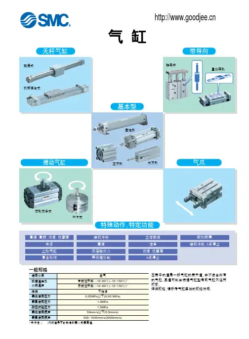
!"#$%
MGP (ø12
ø100)
· 体积小、轻巧。
· 耐横向负载能力强。
· 耐扭矩能力强。
· 不回转精度高。
· 导向杆的轴承可选择滑动轴承或球轴承。
· 安装方便。
· 二面接管位置可供选择。
最大横向负载F(N) 最大扭矩T(N •m)
扭矩:T(N
型号表示方法
* 中间行程间隔为1mm(ø12~ø32)或5mm(ø40~ø100); 若需要非标准行程需加垫板于标准 行程气缸内。
** 磁性开关规格及特性可参阅磁性开关系列。
在磁性开关型号后,附 导线长度表示记号:无记号-0.5m ,L -3m ,Z-5m 。
例:Y59A, Y59AL
行程/磁性开关型号
MGPM , MGPL 共同尺寸表
4-NN通孔4-øOA 通孔
4-øOB 沉孔深OL
PA + 行程
XX部详细图
C + 行程
B + 行程
A + 行程
12 ~ ø25
深
深
部
深
深
部
部
深
!"=E F
XX 部详细图
32 ~ ø63
MGPM (滑动轴承)尺寸A,DB,E
MGPL (球轴承)尺寸A,DB,E
4-NN 通孔
4-øOA 通孔
4-øOB 沉孔深OL
C + 行程B + 行程A + 行程
PA + 行程深部
深
部
深
深
部
深
ø80 ~ ø100
MGPM (滑动轴承)
MGPL (球轴承)
st = 行程
MGPM , MGPL 共同尺寸表
XX 部详细图
4-NN 通孔
4-øOA 通孔
4-øOB 沉孔深OL
PA + 行程
C + 行程B + 行程
A + 行程
深
部
深部
深部
深ø6H7深10
6H7
10
ø6H7深10
ø6H7深10
5
7
ø6H 7
规格
缸径(mm)
最高使用压力(MPa)最低使用压力(MPa)缓冲
*其它规格参见P.1.197。
16
0.15
0.1220,25,32,40,50,63,80,100
1.0
缸径(mm)
1620~6380·100
标准行程表
两侧气缓冲
规格
缸径(mm)
使用压力范围(MPa)使用活塞速度(mm/s)缓冲
标准行程(mm)端板不回转精度
50
±0.05°
±0.04°50~40025,50,75,100,125,150,175,20080
0.1~1.0两侧垫缓冲
标准行程
25,50,75,100,125,150,175,200,250
25,50,75,100,125,150,175,200,250,300,350,40050,75,100,125,150,175,200,250,300,350,400
[粗导杆型]*其它规格参见P.1.197。
*其它规格参见P.1.197。
缸径无记号Rc N NPT TF
G
无记号2个S
1个
无记号无磁性开关
(内置磁环)
50mm 80mm
8050*磁性开关型号参见 P.1.197。
(mm)。