SMC气缸第一册(执行元件)D
- 格式:pdf
- 大小:17.77 MB
- 文档页数:96
新型SMC气缸的及安装方法新型SMC气缸及安装方法气动执行元件是气动系统的紧要构成部分,而气缸是其中最常用的一种。
气缸的使用范围非常广泛,从家电家具到工业自动化,无处不在。
随着技术的进展和市场的需求,新型的气缸产品不断被设计和推出,更为智能、高效、耐用。
本文将介绍一种新型SMC气缸及其安装方法,并对其特点进行分析和评价。
SMC气缸是一种高性能的气动执行元件。
它是日本SMC公司生产的一种气缸产品,采纳了先进的制造工艺和材料,具有精度高、响应速度快、使用寿命长等优良特性,广泛应用于机械、电子、移动电话、汽车和医疗等领域。
新型SMC气缸重要有以下几个特点:1.使用寿命长。
SMC气缸采纳优质材料制造,在耐磨性和耐腐蚀性方面表现杰出。
同时,该产品还具有良好的密封性能,能够有效地防止气体泄漏,延长使用寿命。
2.精度高。
SMC气缸具有精密的内部结构和高效的掌控系统,能够实现精准明确的位置掌控,提高了生产效率和质量。
3.响应速度快。
SMC气缸的响应速度特别快,同时,其掌控系统也具有高效的精准度和牢靠性,能够适时响应操作命令,提高整个系统的反应速度。
4.维护和安装简单。
SMC气缸采纳简洁的结构设计和组件,易于安装和维护。
同时,该产品还供给认真的使用说明和安装手册,便利用户使用和操作。
了解了新型SMC气缸的特点,我们接下来将介绍该产品的安装方法。
安装SMC气缸的步骤如下:1.安装气源和气路。
在安装SMC气缸前,需要首先安装气源和气路,使气体能够顺当通过气管传递到气缸。
2.选择合适的安装位置。
在安装气缸的位置上,应依据气缸的性质和使用需求进行选择。
一般来说,气缸的安装位置最好是离液体和强磁场等干扰物体较远的地方。
3.安装气缸。
依据气缸的安装方向和安装方式,将气缸安装到合适的位置。
在安装气缸时,应注意气管的尺寸、气缸与气管的连接方式、气缸的固定方式等因素。
4.连接掌控用线路。
依据需要,将气缸与掌控用线路进行连接,实现气缸的远程掌控。
SMC气动基础知识培训课件.一、教学内容本节课我们将学习《SMC气动基础知识》教材的第一章节,详细内容涉及气动元件的基本原理、气动系统的构成、气动执行元件的工作原理及其在自动化设备中的应用等。
二、教学目标1. 理解并掌握气动元件的基本原理及其在气动系统中的作用。
2. 学会分析气动系统的构成,了解各部分的功能和相互关系。
3. 掌握气动执行元件的工作原理,能够进行简单的气动设备故障排查。
三、教学难点与重点1. 教学难点:气动执行元件的工作原理及气动系统的设计。
2. 教学重点:气动元件的基本原理、气动系统的构成及各部分功能。
四、教具与学具准备1. 教具:SMC气动元件实物、气动系统演示装置、PPT课件。
2. 学具:笔记本、教材、计算器。
五、教学过程1. 导入:通过展示气动设备在工业生产中的应用,引发学生对气动知识的兴趣。
2. 新课内容:详细讲解气动元件的基本原理、气动系统的构成、气动执行元件的工作原理。
a. 气动元件基本原理:利用PPT展示气动元件的图片,讲解其工作原理。
b. 气动系统构成:分析气动系统各部分的功能和相互关系。
c. 气动执行元件:结合实物,讲解气动执行元件的工作原理。
3. 实践情景引入:展示气动设备故障排查实例,让学生了解气动知识在实际中的应用。
4. 例题讲解:针对气动系统的设计,进行例题讲解,巩固所学知识。
5. 随堂练习:布置相关练习题,让学生及时巩固所学内容。
六、板书设计1. 气动元件基本原理2. 气动系统构成气源部分控制部分执行部分3. 气动执行元件工作原理4. 气动设备故障排查实例七、作业设计1. 作业题目:a. 列举气动元件的基本原理。
b. 简述气动系统的构成及其各部分功能。
c. 解释气动执行元件的工作原理。
2. 答案:a. 气动元件基本原理:利用压缩空气作为动力源,实现机械部件的运动或控制。
b. 气动系统构成:气源部分(空气压缩机、气罐等)、控制部分(气动控制阀、电磁阀等)、执行部分(气缸、气马达等)。
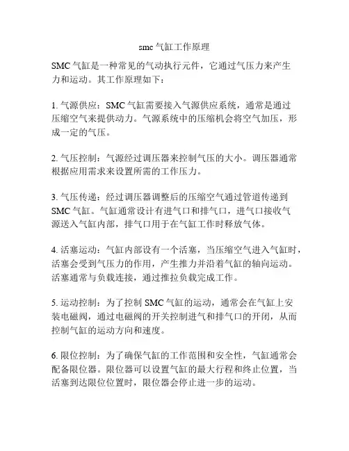
smc气缸工作原理
SMC气缸是一种常见的气动执行元件,它通过气压力来产生
力和运动。
其工作原理如下:
1. 气源供应:SMC气缸需要接入气源供应系统,通常是通过
压缩空气来提供动力。
气源系统中的压缩机会将空气加压,形成一定的气压。
2. 气压控制:气源经过调压器来控制气压的大小。
调压器通常根据应用需求来设置所需的工作压力。
3. 气压传递:经过调压器调整后的压缩空气通过管道传递到SMC气缸。
气缸通常设计有进气口和排气口,进气口接收气
源送入气缸内部,排气口用于在气缸工作时释放气体。
4. 活塞运动:气缸内部设有一个活塞,当压缩空气进入气缸时,活塞会受到气压力的作用,产生推力并沿着气缸的轴向运动。
活塞通常与负载连接,通过推拉负载完成工作。
5. 运动控制:为了控制SMC气缸的运动,通常会在气缸上安
装电磁阀,通过电磁阀的开关控制进气和排气口的开闭,从而控制气缸的运动方向和速度。
6. 限位控制:为了确保气缸的工作范围和安全性,气缸通常会配备限位器。
限位器可以设置气缸的最大行程和终止位置,当活塞到达限位位置时,限位器会停止进一步的运动。
通过以上工作原理,SMC气缸可以在许多自动化设备和工业
应用中实现各种动作,如推拉、抓取、夹持等。
它的简单结构、可靠性和高效性使其成为气动系统中的重要组成部分。
如何调整SMC气缸的快慢SMC气缸是一种常见的气动执行器,通过气源供应的气压掌控气缸的动作,从而实现工作装置的运动。
气缸的基本构成部分包含缸筒、缸盖、活塞、活塞杆等。
SMC气缸的工作原理是:气源供应的气压通过气缸进入缸筒内,在活塞作用下推动工作装置完成工作。
气压大小决议了气缸的工作力度,因此正确调整气压大小至关紧要。
二、气缸气压大小的调整方法1.确定所需气压大小在使用气缸前,需要确定所需的气压大小。
一般来说,工作环境越恶劣、运动速度越快、负载越重,所需的气压越高。
因此,需要依据实际使用情况来确定所需的气压大小。
2.调整气源压力气源压力对气缸的气压大小起到决议性作用。
可通过调整气源压力来调整气压大小。
此处需注意,气源压力不宜过高,应依据气缸额定压力范围进行调整。
3.调整气缸出气口调整阀气缸出气口调整阀也称气压调整阀,可以掌控气源进入气缸的气量,从而实现气压调整。
依照实际需要,渐渐调整气缸出气口调整阀,直到获得所需的气压。
4.调整缓冲装置部分气缸具有缓冲装置,可以减缓气缸末端移动过程中的撞击力,从而保护工作装置。
在调整气压大小时,也需对缓冲装置进行适当的调整,以获得更加平稳的气压输出。
一、SMC气缸是气动执行元件之一,重要由缸体、活塞、活塞杆等构成。
在气动系统中起到将压缩空气转化为动力的作用。
二、SMC气缸的快慢调整方法有多种,其中比较常用的方法有以下几种:1.调整进出口气压:通过调整进口气压和出口气压的大小来掌控气缸的速度。
出口气压越大,气缸速度越快;出口气压越小,气缸速度越慢。
2.调整活塞杆上的空气孔径:加添活塞杆上的空气孔径可以加添空气的流量,使气缸速度变快;减少空气孔径可以降低空气流量,使气缸速度变慢。
3.调整限位阀:限位阀可以掌控活塞杆的行程,从而调整气缸的快慢。
可以通过调整限位阀的开度来掌控气缸的速度。
三、SMC气缸快慢调整注意事项在进行气缸快慢调整的时候,要注意以下事项:1.调整前要先检查气路和管路,确保正常无堵塞,以免影响调整效果;2.在调整过程中,要分别调整进口气压和出口气压,以避开显现偏差;3.不要将气缸的速度调整得过快或者过慢,应当依据实际需要进行合理调整;4.在调整限位阀的时候,要注意阀门的位置,不能过度调整,以免影响气缸的使用寿命;5.调整后要进行测试,确保气缸的运行速度和压力都符合设计要求。
SMC气缸选型1. 引言气缸作为一种常用的执行元件,被广泛应用于各行各业的自动化控制系统中。
而SMC作为全球领先的气动元件制造商,其产品质量和性能一直备受认可。
本文将介绍如何选择适合需求的SMC气缸,并给出一些建议。
2. SMC气缸的分类SMC气缸按照不同的分类标准可以分为多个类型,包括气缸结构、驱动方式、工作方式等。
下面将介绍几种常见的SMC气缸类型:2.1 作用方式•单作用气缸:只有一端有工作效果,通常用于对于单向推拉或者升降动作的应用。
•双作用气缸:两端都可以进行推拉动作,广泛应用于工业自动化控制系统中。
2.2 结构类型•直杆气缸:气缸中心有一根直杆,可实现直线运动。
•短杆气缸:杆短于缸体,适用于安装空间有限的场合。
•载荷导向气缸:提供强大的承载能力和抗侧向载荷能力。
•旋转气缸:通过旋转实现推拉动作。
2.3 驱动方式•气压驱动:通过气源驱动,便于控制和调节。
•电动驱动:通过电机驱动,可直接接入电气系统。
3. 选型要点选择适合的SMC气缸需要考虑以下几个要点:3.1 载荷确定需要承载的最大载荷和工作环境下的载荷类型(轴向、径向或复合载荷等),以选择适当的载荷导向气缸。
3.2 快速性能根据应用场景中运动速度的要求,选择具备相应流量的气缸产品,以确保推拉速度满足要求。
3.3 工作压力根据工作环境中的压力要求和实际压力,选择合适的气缸型号和尺寸,以确保气缸能稳定工作。
3.4 工作温度考虑工作环境的温度范围,选择能在高温或低温环境下正常工作的气缸材料和密封件。
3.5 安装空间根据安装空间的限制,选择适当大小和形状的气缸,以确保能够方便地安装和维护。
4. 选型示例根据以上选型要点的考虑,以下是一个选型示例:4.1 应用场景假设我们需要选择适合挤压机械中的推拉动作的SMC气缸。
4.2 选型步骤1.确定最大载荷:根据挤压机械的工作参数,确定最大推拉载荷为1000N。
2.确定快速性能:根据挤压机械的要求,需要推拉速度为1m/s。
smc气缸标准件库下载在工业生产中,smc气缸作为一种常见的执行元件,在自动化设备中发挥着重要的作用。
而为了更好地应用smc气缸,我们需要了解其相关的标准件库下载信息。
首先,我们需要明确smc气缸的基本特点和工作原理。
smc气缸是一种利用压缩空气产生的动力来驱动活塞运动,从而实现机械设备运转的装置。
它具有结构简单、可靠性高、使用寿命长的特点,在自动化生产线上得到广泛应用。
其次,我们需要了解smc气缸的标准件库下载信息。
在进行smc气缸的选择和应用时,我们可以通过访问官方网站或者相关的工业标准数据库,获取smc气缸的标准件库下载信息。
这些标准件库包括气缸的CAD图纸、技术参数、安装说明等内容,能够帮助工程师更好地进行气缸的设计和选择。
除此之外,我们还可以通过专业的工业设备供应商获取smc气缸的标准件库下载信息。
这些供应商通常会提供包括气缸的3D模型、配件清单、使用手册等在内的完整标准件库,方便工程师们在设计和使用过程中进行参考和借鉴。
在使用smc气缸的过程中,我们需要注意以下几点。
首先,要严格按照气缸的安装说明进行安装,确保气缸能够正常工作。
其次,要定期检查气缸的密封件和活塞杆,保持其良好的工作状态。
最后,要根据气缸的使用环境和工作要求,选择合适的气缸配件和控制元件,确保整个系统的稳定性和可靠性。
综上所述,smc气缸作为一种重要的执行元件,在工业自动化领域发挥着重要的作用。
通过了解其基本特点和工作原理,以及获取其标准件库下载信息,我们能够更好地应用和选择smc气缸,提高生产效率,降低成本,实现智能制造。
希望本文能够帮助大家更好地了解和应用smc气缸,推动工业自动化技术的发展和进步。
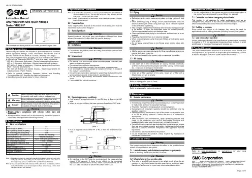
VR12F-TF222-005ENPage 1 of 1Instruction ManualAND Valve with One-touch FittingsThe intended use of this product is to control pneumatic signal lines.These safety instructions are intended to prevent hazardous situations and/or equipment damage. These instructions indicate the level of potential hazard with the labels of “Caution,” “Warning” or “Danger.” They are all important notes for safety and must be followed in addition to International Standards (ISO/IEC) *1), and other safety regulations. *1)ISO 4414: Pneumatic fluid power - General rules relating to systems. ISO 4413: Hydraulic fluid power - General rules relating to systems.IEC 60204-1: Safety of machinery - Electrical equipment of machines. (Part 1: General requirements)ISO 10218-1: Robots and robotic devices - Safety requirements for industrial robots - Part 1: Robots.• Refer to product catalogue, Operation Manual and Handling Precautions for SMC Products for additional information. • Keep this manual in a safe place for future reference.Warning • Always ensure compliance with relevant safety laws and standards.• All work must be carried out in a safe manner by a qualified person in compliance with applicable national regulations.2 SpecificationsNote 1) Use caution when the maximum operating pressure is used with soft nylonand polyurethane. Depending on the temperature, these tubes have a lower operating pressure. Refer to the specification of the tubes.Note 2) Two axes (horizontal and vertical) and two directions were tested, and nomalfunction of the valve occurred (pulse shape: sine shape), 3 times (test sample mounted with bracket).Note 3) No malfunction occurred in a sweep cycle test between 10 to 150 Hz atvibration sweep 0.35 mm. The test was performed in the two axes and two directions, 7 min per cycle (20 cycles).Note 4) Brass components are all electroless nickel plated as standard. (Copper-free and fluorine-free)2.2 Response timeValve response time depends on the overall circuit design, so it must be determined by the circuit designer. 2.3 Special productsWarningSpecial products (-X) might have specifications different from those shown in this section. Contact SMC for specific drawings.3 Installation3.1 InstallationWarning• Do not install the product unless the safety instructions have been read and understood. 3.2 EnvironmentWarning• Do not use in an environment where corrosive gases, chemicals, salt water or steam are present.• Do not use in an explosive atmosphere.• Do not expose to direct sunlight. Use a suitable protective cover.• Do not install in a location subject to vibration or impact in excess of the product’s specifications.• Do not mount in a location exposed to radiant heat that would result in temperatures in excess of the product’s specifications.• Do not use in high humidity environment where condensation can occur.• Contact SMC for altitude limitations.3.3 Operating pressure conditions• Only when air is supplied to both P1 and P2 does air flow to the OUT side.• When air pressure differs, the lower pressure flows to the OUT side.Figure 1.• If air is supplied only to either P1 or P2, it does not flow to the OUT side.Figure 2.Warning• Air may flow to the OUT side for a moment until the valve switches (About 1/100 second). If there is any effect on the connected equipment due to the above air flow, install a speed controller, etc, on the OUT side, and adjust to prevent this effect before use.3.4 PipingCaution• Before connecting piping make sure to clean up chips, cutting oil, dust etc.• When installing piping or fittings, ensure sealant material does not enter inside the port. When using seal tape, leave 1 thread exposed on the end of the pipe/fitting.• Stop using the equipment immediately when air leaks are large enough to be audible, or when the equipment does not operate properly. Perform appropriate function and leakage tests.• Check periodically that piping is not loosened and that there is no air leakage.• Regularly check that there is no external damage.• When connecting tubes using One-touch fittings, provide some spare tube length.• Do not apply external force to the fittings when binding tubes with bands.Caution• SMC products have been lubricated for life at manufacture, and do not require lubrication in service.• If a lubricant is used in the system, refer to catalogue for details. 3.5 Air supplyWarning• Use clean air. If the compressed air supply includes chemicals, synthetic materials (including organic solvents), salinity, corrosive gas etc., it can lead to damage or malfunction.Caution• Install an air filter upstream of the valve. Select an air filter with a filtration size of 5 μm or smaller.4 How to OrderRefer to catalogue for ‘How to Order’.5 Outline DimensionsRefer to catalogue for outline dimensions.6 Maintenance6.1 General maintenanceCaution• Not following proper maintenance procedures could cause the product to malfunction and lead to equipment damage.• If handled improperly, compressed air can be dangerous.• Maintenance of pneumatic systems should be performed only by qualified personnel.• Before performing maintenance, turn off the power supply and be sure to cut off the supply pressure. Confirm that the air is released to atmosphere.• After installation and maintenance, apply operating pressure and power to the equipment and perform appropriate functional and leakage tests to make sure the equipment is installed correctly.• If any electrical connections are disturbed during maintenance, ensure they are reconnected correctly, and safety checks are carried out as required to ensure continued compliance with applicable national regulations.• Do not make any modification to the product.• Do not disassemble the product, unless required by installation or maintenance instructions.7 Limitations of UseWarningThe system designer should determine the effect of the possible failure modes of the product on the system.7.1 Limited warranty and disclaimer/compliance requirements Refer to Handling Precautions for SMC Products.Warning7.2 Effect of energy loss on valve state• The valve is an AND logic element in an all-air circuit. When the air pressure is cut to both inputs the valve goes into an undefined state. Backflow of air from out to in port may occur under this condition.• It is the responsibility of the system designer to determine the effect in the system when air pressure is cut and when it is restored. 7.3 Cannot be used as an emergency shut-off valveThis product is not designed for safety applications such as an emergency shut-off valve. If the valves are used in this type of system, other reliable safety assurance measures should be adopted.7.4 Holding of pressureSince valves are subject to air leakage, they cannot be used for applications such as holding pressure (including vacuum) in a system.Caution7.5 Low temperature operationUnless otherwise indicated in the specifications for each valve, operation is possible to -5˚C, but appropriate m easures should be taken to avoid solidification or freezing of drainage and moisture, etc.8 Product DisposalThis product shall not be disposed of as municipal waste. Check your local regulations and guidelines to dispose this product correctly, in order to reduce the impact on human health and the environment.9 ContactsRefer to or www.smc.eu for your local distributor/importer.URL : https:// (Global) https:// www.smc.eu (Europe) SMC Corporation, 4-14-1, Sotokanda, Chiyoda-ku, Tokyo 101-0021, JapanSpecifications are subject to change without prior notice from the manufacturer. © 2022 SMC Corporation All Rights Reserved. Template DKP50047-F-085MORIGINAL INSTRUCTIONS2 (OUT)(IN) 1 (IN) 1IN P 1 IN P 2 OUT OUTOUT IN P 1 IN P 2 IN P 1 IN P 2。
smc气缸工作原理
SMC气缸是一种常用的气动执行元件,用于将压缩空气的动
能转换为机械能。
其工作原理可以简要描述为下:
1. 压缩空气供给:SMC气缸通过气源供给系统获取压缩空气,通常配备压缩空气提供设备,如气泵或压缩空气管路系统。
2. 空气进入:一旦气源供给被打开,压缩空气就会进入气缸的气腔内部,受到活塞的阻挡。
3. 活塞作用:气缸内部有一个活塞,活塞随着压缩空气的进入而受到推力,从而开始移动。
4. 推力传递:活塞的运动将推动与其连接的机械装置或零件进行相应运动,实现所需的机械工作。
气缸一般具有单向传动性能,即只能在一个方向上进行推力传递。
5. 排气:当活塞完成工作任务后,气缸内部的压缩空气需得到排放,以便下一次工作循环的开始。
这通常通过排气阀门或间歇式排放装置来实现。
6. 循环工作:SMC气缸可以根据需要循环工作,以实现连续
的机械工作。
在工作周期中,气源供给和排气循环交替进行,活塞则依靠压缩空气推动进行工作。
以上是SMC气缸的基本工作原理。
根据具体应用和设计要求,气缸可能有不同的构造和特性,但其工作原理基本相似。
气缸用气量计算怎样计算气缸的耗气量,谢谢!!!Qmax=0.047D*D*s(P+0.1)/0.1*1/t Qmax---最大耗气量L/min D--------缸经,cmt---------气缸一次往返所需的时间,sP-------工作压力,MPat---------气缸一次往返所需的时间,s 若是电磁阀控制,这个t 怎么确定呀?可以计算平均耗气量Q=0.00157ND*D*s(P+0.1)/0.1Q---平均耗气量L/min D--------缸经,cmN--------气缸每分钟的往返次数 P-------工作压力,MPa是不是还应该与实际行程或活塞的平均速度有关系呀。
气动系统的设计一.工作方式设计1.运动一的工作顺序图(单个工作周期为19秒)2.运动二的工作顺序图(单个工作周期为42秒)3. 运动三的工作顺序图(单个工作周期为53.5秒)〈下一页〉二.执行元件选择1、执行元件耗气量计算:查《机械设计手册》第5分册,可知伸缩型气缸的耗气量:有活塞杆腔时,无活塞杆腔时,3式中:q v1——缸前进时(杆伸出)无杆腔(包括柱塞缸)压缩空气消耗量(m /s) ;q v2——缸后退时(杆缩回)有杆腔压缩空气消耗量(m 3/s) ; D ——气缸内径(柱塞缸的柱塞直径)(m ) d ——活塞杆直径 (m )t 1——气缸前进(杆伸出)时完成全行程所需时间 (s )t 2——气缸后退(杆缩回)时完成全行程所需时间 (s ) s ——缸的行程 (m )查SMC 培训教材《现代实用气动技术》,可知摆动气缸的耗气量:式中:q rH ——摆动气缸的最大耗气量;(L /min ) V ——摆动气缸的内部容积;(cm )3P ——使用压力,(MPa ) t ——摆动时间,(s ) ① 夹紧气缸:已知气缸内径D =0.040(m ) ,行程s =0.04(m ) ,全行程所需的时间t 1=0.5(s ) 那么该气缸的耗气量:② 伸缩气缸:已知气缸内径D =0.032(m ) ,活塞杆直径d =0.012(m ) ,行程s =0.5(m ) ,全行程所需的时间t 2=2(s )那么该气缸的耗气量:③ 手腕回转气缸:已知气缸体积V =94.25(cm ) ,使用压力P =0.5(MPa ) ,摆动时间t =0.5(s )3那么该气缸的耗气量:④ 手臂升降气缸:已知气缸内径D =0.05(m ) ,活塞杆直径d =0.02(m ) ,行程s =0.3(m ) ,全行程所需的时间t 2=1.5(s )那么该气缸的耗气量:⑤ 摆动气缸:已知气缸体积V =1300(cm ) ,使用压力p =0.5(MPa ) ,摆动时间t =2(s )3那么该气缸的耗气量:则,各执行元件的类型与主要尺寸参数如下表3-1表3-1 各执行元件类型及尺寸参数〈上一页〉〈下一页〉三.控制元件选择1. 类型初定根据气动回路系统对控制元件的流量要求、工作压力、工作环境及工作可靠性,结合气动回路原理图,初选各控制阀如下:主控电磁换向阀:全部选用SMC 的VFS 系列,通径待定;单向节流阀:全部选用SMC 的AS 系列,通径待定。
产品名称:SMC气缸cda系列
SMC气缸引导活塞在其中进行直线往复运动的圆筒形金属机件。
工质在发动机气缸中通过膨胀将热能转化为机械能;气体在压缩机气缸中接受活塞压缩而提高压力。
涡轮机、旋转活塞式发动机等的壳体通常也称“气缸”。
气缸的应用领域:印刷(张力控制)、半导体(点焊机、芯片研磨)、自动化控制、机器人等等,气压传动中将压缩气体的压力能转换为机械能的气动执行元件。
气缸有作往复直线运动的和作往复摆动的两类(见图)。
作往复直线运动的气缸又可分为单作用、双作用、膜片式和冲击气缸4种。
将压缩空气的压力能转换为机械能,驱动机构作直线往复运动、摆动和旋转运动,直线运动往复运动的气缸、摆动运动的摆动气缸、气爪等。
smc标准气缸SMC标准气缸。
SMC标准气缸是一种常用的气动执行元件,广泛应用于工业自动化领域。
它具有结构简单、性能可靠、使用寿命长的特点,适用于各种机械设备的传动和控制。
本文将从SMC标准气缸的工作原理、结构特点、应用范围等方面进行介绍。
首先,让我们来了解一下SMC标准气缸的工作原理。
SMC标准气缸是利用气体压力来产生直线运动的装置。
当气缸内充入压缩空气时,气缸内活塞受到气压作用而产生推力,从而驱动负载实现直线运动。
当气缸排气时,气缸内的压力降低,活塞受到外部负载的作用而产生回位运动。
这种通过气压来驱动活塞的工作原理,使得SMC标准气缸在自动化控制系统中具有重要的作用。
其次,我们来看一下SMC标准气缸的结构特点。
SMC标准气缸通常由气缸筒、活塞、密封件、导向件、活塞杆等部件组成。
气缸筒是气缸的主体部分,通常由铝合金或不锈钢制成,具有良好的耐腐蚀性和耐磨性。
活塞是气缸的运动部件,其表面通常经过特殊处理,以提高密封性能和耐磨性。
密封件是保证气缸密封性能的关键部件,通常采用优质的氟橡胶或聚氨酯材料制成。
导向件用于引导活塞在气缸筒内的运动轨迹,以保证气缸的运动稳定性和精度。
活塞杆连接活塞和外部负载,通常采用优质的合金钢材料制成,以承受较大的拉伸和压缩载荷。
最后,让我们来探讨一下SMC标准气缸的应用范围。
SMC标准气缸广泛应用于各种机械设备的传动和控制,如注塑机械、冲压机械、包装机械、木工机械等。
在这些设备中,SMC标准气缸通常用于实现夹紧、顶推、拉伸、定位等动作,其稳定可靠的性能得到了用户的一致好评。
此外,SMC标准气缸还可以与传感器、阀门、控制器等配件组合成各种自动化控制系统,实现工艺流程的自动化和智能化。
总的来说,SMC标准气缸作为一种重要的气动执行元件,在工业自动化领域具有广泛的应用前景。
它的工作原理简单清晰,结构稳定可靠,适用范围广泛,为各种机械设备的传动和控制提供了重要的支持。
相信随着工业自动化技术的不断发展,SMC标准气缸将会发挥越来越重要的作用,为工业生产带来更大的便利和效益。
※导线长度表示记号0.5m ……………无记号 (例)M9NW 1m …………… M (例)M9NWM 3m …………… L (例)M9NWL 5m …………… Z (例)M9NWZ 无…………… N (例)H7CN ※带"O"的无触点磁性开关按订货生产。
※除本表型号外,还可能安装的磁性开关参见P.16。
※导线前置插头的磁性开关参见《Best Pneumatics 》第二册P.1328、1392。
※D-A9□(V ), M9□(V ), M9□W (V ),M9□A (V )型磁性开关一同包装出厂(未组装)。
(但磁性开关安装件组装出厂。
)※※※防水性强型磁性开关,可以安装在上述产品上,但是不能由此保证上述产品的防水性。
在防水坏境下,推荐使用具有防水性的产品。
其中,关于ø20、ø25的防水性产品,请联系本公司型号表示方法N N 带磁性开关气缸行程(※※安装件和气缸一同包装出厂。
※安装件F, G, L, D 对应的气缸为Z :基本型(无耳轴安装用螺孔)。
※杆端螺纹形状为内螺纹时,无连接件。
※杆端连接件和气缸一同包装出厂。
※单肘节接头中不包含销轴。
RoHS1气缸/标准型 :单杆双作用ø20, ø25, ø32, ø40, ø50, ø63, ø80, ø100CG1 系列乐清市顺力气动有限公司http://www.slqd.cn乐※对于ø80, ø100,没有基本型(无耳轴安装用螺孔)、杆侧耳轴型、无杆侧耳轴型。
对于ø20~ø63的脚座型、法兰型、耳环型,没有耳轴安装用内螺纹。
使用时,请不要超过允许动能。
详细情况请参考P.4。
缸径(mm )动作方式给油使用流体耐压试验压力最高使用压力最低使用压力环境温度及使用流体温度使用活塞速度行程长度允差缓冲安装形式※单杆双作用不要(不给油)空气1.5MPa1.0MPa 0.05MPa 无磁性开关:−10℃~70℃(未冻结时)带磁性开关:−10℃~60℃~200st mm (ø20)~300st mm (ø25~ø100)垫缓冲0.28J 0.11J0.41J 0.18J0.66J 0.29J1.20J 0.52J2.00J 0.91J3.40J 1.54J5.90J 2.71J9.90J 4.54J +1.40+1.40基本型、基本型(无耳轴安装用螺孔)、轴向脚座型、杆侧法兰型、无杆侧法兰型、杆侧耳轴型、无杆侧耳轴型、耳环型(通口位置作90°变更时使用)※ø80, ø100没有杆侧耳轴型和无杆侧耳轴型。