define_grid_motion的使用形式
- 格式:doc
- 大小:12.50 KB
- 文档页数:2
FLUENT动网格需要的常用宏虽然瞬态PROFILE文件可以在一定程度上定义网格运动,然而其存在着一些缺陷。
最主要的一些缺陷存在于以下一些方面:(1)PROFILE无法精确的定义连续的运动。
其使用离散的点值进行插值。
如果想获得较为精确的运动定义,势必要定义很多点。
(2)一些情况下无法使用profile。
比如稳态动网格。
在FLUENT中定义网格运动,更多的是采用UDF宏。
fluent中与动网格有关的UDF 宏一共有5个,其中四个用于常规的网格运动定义,一个用于6DOF模型。
这些宏分别为:DEFINE_CG_MOTION、DEFINE_DYNAMIC_ZONE_PROPERTY、DEFINE_GEOM、DEFINE_GRID_MOTION、DEFINE_SDOF_PROPERTIES注意:动网格宏只能为编译型UDF。
1、DEFINE_CG_MOTION最常用的运动网格宏。
用户可以使用该宏定义每一时间步上的线速度或角速度来指定fluent中某一特定区域的运动。
DEFINE_CG_MOTION(name,de,vel,omega,time,dtime)参数说明:name:UDF的名字。
体现在fluent中表现为可选择的函数列表。
Dynamic_Thread *dt:存储了用户所指定的动网格属性和结构指针。
real vel[]:线速度。
vel[0]为x方向速度,vel[1]为y方向速度,vel[2]为z 方向速度real omega[]:角速度。
与线速度定义相同。
real time:当前时间。
real dtime:时间步长。
函数返回值为:void从函数的参数类型,配合c语言的参数调用方式可知,vel,omega为数值类型,属于传入类型。
因此只需在函数体中显式定义vel与omega即可将速度传入fluent求解器。
time与dtime是用于定义速度的。
详细实例可参看fluent udf 文档p182。
2、DEFINE_DYNAMIC_ZONE_PROPERTY该宏能用于以下一些场合:(1)在in-cylinder应用中定义旋转中心。

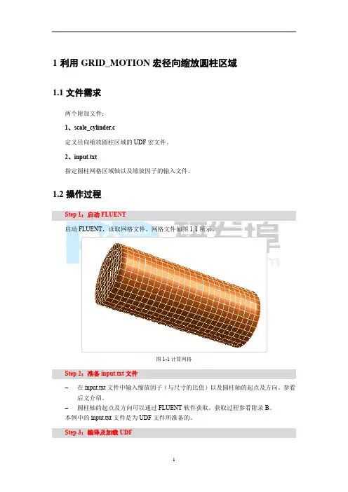
以NACA0012翼型俯仰振荡实例进行讲解动网格的应用过程;首先需要声明的是,这个例子也是来源于网络,原作者不详,在此向他表示感谢。
1、问题描述本例是想对作简谐振荡运动的NACA0012翼型的气动特性(升力系数,阻力系数和力矩系数)进行数值计算,来流速度为V,攻角的变化规律为:Alpha(t)=A/2*sin(omega*t)其中,A=10度,omega=10*pi 弧度/秒。
2、该例需要使用动网格来实现,首先需要编写刚体运动UDF实现翼型的俯仰运动,由于在FLUENT的UDF中只能指定速度,角速度;所以,需要将攻角对时间求导,得到转动角速度的规律:D(alpha)/dt=A*omega/2*cos(omega*t)编写的UDF在附件中。
3、由于本例只是为了讲述动网格的实现,至于其他方面的设置及分析就不再讨论;这里详细讲述下动网格的建立以及动网格的预览的结果。
步骤如下:1)将mesh文件读入到FLUENT中,Grid:check,scale…,Smooth/Swap…;Display Grid;2)定义求解器为,Define:pressure-based,2D,unsteady,Implicit,Green-Gauss Node Based(因本例使用的是三角形单元).3)编译UDF,Define->User-Defined->Functions->Complied…此时打开了Complied UDFs的窗口,Add…在选择UDF的对话框中找到NACA0012DM文件夹中的airfoil.c文件,选中,ok;此时返回到Complied UDFs的窗口点击Build,FLUENT开始进行编译,可以在FLUENT窗口看到编译的一些过程提示;等编译完成,点击Load;就将已经编译好的UDF加载到FLUENT中了。
4)定义动网格参数,Define->Dynamic Mesh(选勾,激活动网格模型)->Parameters…此时打开了Dynamic Mesh Parameters 窗口,在Models中只选取Dynamic Mesh,本例的网格类型为三角形单元,要实现的运动为小幅度的转动,因此选用的动网格更新方法为Smoothing+Remeshing;开始依次对这两种更新方法进行参数设定:Smoothing中的参数设定:Spring Constant Factor(弹簧倔强系数),该值设定为一个较小的值,在0.01到0.1之间,本例选取0.08;Boundary Node Relaxation(边界节点松弛),设定为0.5;Convergence Tolerance(收敛判据),保持默认的0.001;Number of Iterations(迭代次数),保持默认的20;Remeshing中的参数设定:为了得到较好的网格更新,本例在使用局部网格重新划分方法时,使用尺寸函数,也就是Remeshing+Must Improve Skewness+Size Function的策略。
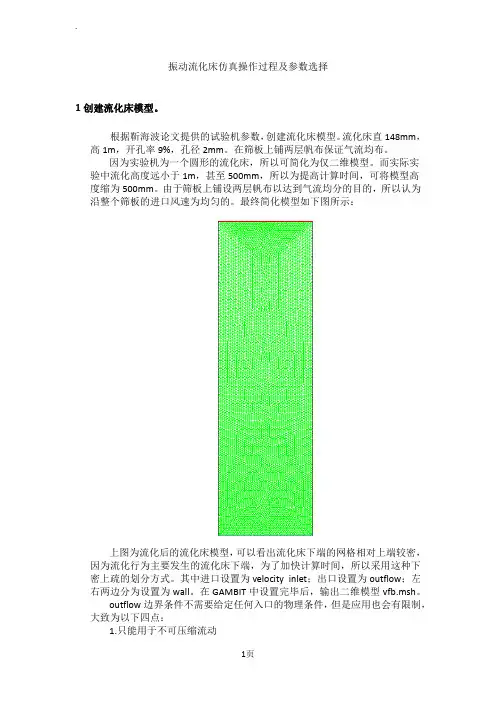
振动流化床仿真操作过程及参数选择1创建流化床模型。
根据靳海波论文提供的试验机参数,创建流化床模型。
流化床直148mm,高1m,开孔率9%,孔径2mm。
在筛板上铺两层帆布保证气流均布。
因为实验机为一个圆形的流化床,所以可简化为仅二维模型。
而实际实验中流化高度远小于1m,甚至500mm,所以为提高计算时间,可将模型高度缩为500mm。
由于筛板上铺设两层帆布以达到气流均分的目的,所以认为沿整个筛板的进口风速为均匀的。
最终简化模型如下图所示:上图为流化后的流化床模型,可以看出流化床下端的网格相对上端较密,因为流化行为主要发生的流化床下端,为了加快计算时间,所以采用这种下密上疏的划分方式。
其中进口设置为velocity inlet;出口设置为outflow;左右两边分为设置为wall。
在GAMBIT中设置完毕后,输出二维模型vfb.msh。
outflow边界条件不需要给定任何入口的物理条件,但是应用也会有限制,大致为以下四点:1.只能用于不可压缩流动2.出口处流动充分发展3.不能与任何压力边界条件搭配使用(压力入口、压力出口)4.不能用于计算流量分配问题(比如有多个出口的问题)2打开FLUENT 6.3.26,导入模型vfb.msh点击GRID—CHECK,检查网格信息及模型中设置的信息,核对是否正确,尤其查看是否出现负体积和负面积,如出现马上修改。
核对完毕后,点击GRID-SCALE 弹出SCALE GRID窗口,设置单位为mm,并点击change length unit按钮。
具体设置如下:3设置求解器保持其他设置为默认,更改TIME为unsteady,因为实际流化的过程是随时间变化的。
(1)pressure based 求解方法在求解不可压流体时,如果我们联立求解从动量方程和连续性方程离散得到的代数方程组,可以直接得到各速度分量及相应的压力值,但是要占用大量的计算内存,这一方法已可以在Fluent6.3中实现,所需内存为分离算法的1.5-2倍。
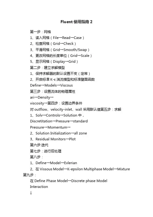
Fluent使用指南2第一步:网格1、读入网格(File→Read→Case)2、检查网格(Grid→Check)3、平滑网格(Grid→Smooth/Swap)4、更改网格的长度单位(Grid→Scale)5、显示网格(Display→Grid)第二步:建立求解模型1、保持求解器的默认设置不变(定常)2、开启标准K-ε湍流模型和标准壁面函数Define→Models→Viscous第三步:设置流体的物理属性ari→Density→viscosity→第四步:设置边界条件对outflow、velocity-inlet、wall 采用默认值第五步:求解1、Solv→Controls→Solution中,Discretitation→Pressure→standardPressure→Momentum→2、Solution Initialization→all zone3、Residual Monitors→Plot第六步:迭代第七步:进行后处理第八步:1、Define→Model→Evlerian2、在Vissous Model→K-epsilon Multiphase Model→Mixture 第九步:在Define Phase Model→Discrete phase ModelInteraction↓选中→Interaction With Continuous Phase Nomber of Continuous PhaseInteractions per DPM Interaction第十步:设置物理属性第十一步:Define→Operating →重力加速度Define→Boondary Conditionsflvid→Mixture→选中Sovrce Terms 其他默认Phase-1→选中Sovrce Terms 其他默认Phase-2→选中Sovrce Terms 其他默认inflow→Mixture→全部默认Phase-1→全部默认Phase-2→Multiphase→Volume Fraction→其他默认outflow→Mixture→默认Phase-1→默认Phase-2→默认wall→Mixture→全部默认Phase-1→默认Phase-2默认第十二步:Slove→Controls→Slution Controls→Pressure→Momentum→其余默认第十三步:千万不能再使用初始化第十四步:进行迭代计算截Z轴上的图:在Surface→iso↓Surface of constant↓Grid↓然后选x、y、z轴(根据具体情况而定)↓在Iso-Values→选取位置C的设置在New Surface Name中输入新各字→点创建然后在Display→Grid→Edge type→Feature→选中刚创建的那个面,然后Display查看刚才那面是否创建对最后在Display→Contours→Options→Filled→Surface→选中面,然后Display。
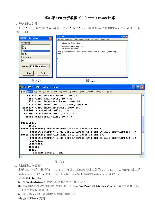
离心泵CFD分析教程(二)--- Fluent计算1、导入网格文件打开Fluent软件选择3d双击,点击File→Read→选择Case→选择网格文件。
如图(1)、(2)、(3)图(1) 图(2)图(3)2、创建网格分界面把进口、叶轮、蜗壳的interface合并,具体的是进口处的interface-in和叶轮进口的interface21合并,叶轮出口的interface23和蜗壳的interface-3合并。
点击Grid Interface(a) 在Grid Interface框里输入分界面的名字,如图(4)(b) 确定组成网格分界面的两分界面区域,在Interface Zone1和Interface Zone 2列表中各选择一个。
(次序无关),如图(4)(c) 点击Create建立新的网格分界面,如图(5)(d) 点击Close关闭图(4)图(5)注:1)创建网格分界面要在check网格之前,否则check网格时就会出错。
2)在创建网格分界面之后你会发现在Boundary Conditions里面多了四个边界(wall-13、wall-25、wall-27、wall-28),如图(6)图(6)3、check网格点击Grid → check,要留意如图(7)所示的volume statistics三项数据是否为正数,若为负数的话就要重新划分网格。
图(7)4、单位换算(scale Grid)点击Grid → scale Grid,在选择㎜,点击→,如图(8)图(8)5、平滑、交换网格点击Grid → Smooth/Swap Grid 如图(9)图(9)点击→,如图(10),继续→直到多次为零而止,如图(11)图(10) 图 (11)注:这对于非结构网格来说非常重要。
6、求解器设置点击Define→Modles→Solver,在Time下面选择steady(定常),点击OK,如图(12) 一般离心泵可选择定常,如果要测算瞬态流的话就要选择Unsteady图(12)7、湍流模型选择点击Define→Modles→Viscous Modle,选择k-epsilon(2kqn), 点击OK,如图(13)图(13)8、设置流体物性点击Define→Materials→右侧Fluent Database(如图14)→在Fluent Fluid Materials 里面选择Water-liquid(H2o<l>)(如图15),点击Copy→Close图(14).9、设置旋转单位点击Define→Units→angular-velocity→rpm→Close,如图(16)如图(16)10、设置运行条件点击Define→Operating Conditions→点击Gravity(重力)前面的小方块,在重力的作用坐标线上填上大小,负号表示重力的方向和坐标方向相反→点击OK在Operating Pressure可以设置参考压力,一般默认为一个大气压。
define_grid_motion的使用形式-回复问题:define_grid_motion的使用形式define_grid_motion是一个功能强大的工具,用于定义和控制网格动画的移动。
它通常用于Web开发中,通过对元素的位置和动画进行精细控制,实现更流畅和吸引人的用户体验。
本文将详细介绍define_grid_motion的使用形式,并提供一步一步的指导。
第一步:安装和导入define_grid_motion库首先,确保你的项目已经安装了define_grid_motion库。
你可以通过在终端中运行以下命令来安装它:npm install define_grid_motion或者,你可以在HTML文件中使用script标签直接导入库的最新版本:html<script src="一旦库安装完毕,你就可以在你的代码中导入它。
javascriptimport { defineGridMotion } from 'define_grid_motion';第二步:创建一个容器元素来进行动画在HTML文件中,你需要创建一个用于显示动画的容器元素。
你可以使用任何HTML元素来作为容器,比如一个div元素。
html<div id="animation-container"></div>第三步:定义和配置网格动画在你的JavaScript代码中,你需要定义和配置网格动画。
首先,获取容器元素的引用:javascriptconst animationContainer =document.getElementById('animation-container');接下来,创建一个网格动画实例,并将它附加到容器上:javascriptconst gridMotion = new defineGridMotion(animationContainer);现在你可以开始定义和配置动画了。
vueuse motion使用Vueuse Motion是一个Vue3的动画库,基于Motion和Framer Motion。
它提供了一组用于创建、控制和组合动画效果的组件和指令。
使用Vueuse Motion,首先需要安装它:```bashnpm install vueuse/motion@next```然后在Vue应用程序的入口文件中引入和使用它:```javascriptimport { createApp } from 'vue'import { motionPlugin } from '@vueuse/motion'import App from './App.vue'const app = createApp(App)e(motionPlugin)app.mount('#app')```接下来,就可以在应用程序中使用动画效果了。
比如,可以使用`<m-motion>`组件来创建动画效果:```vue<template><m-motion :initial="false" :opacity="0" :x="100"><div>Hello Vueuse Motion!</div></m-motion></template>```这里的`<m-motion>`组件接受多个属性,比如`initial`表示初始状态是显示还是隐藏,`opacity`表示透明度,`x`表示水平方向的偏移量等等。
除了使用`<m-motion>`组件,还可以使用`v-motion`指令来为任意元素添加动画效果:```vue<template><div v-motion:fade="'in'">Hello Vueuse Motion!</div></template>```这样,元素就会在页面中淡入淡出。
define grid motion相对坐标系Grid motion is a concept that is commonly used in the field of robotics and computer vision. It refers to the motion of objects or points in a 2D or 3D space relative to a grid-based coordinate system. In this article, we will explore the concept of grid motion in the context of a relative coordinate system in detail, discussing its applications, advantages, and limitations.To begin with, let's understand the basic idea of a grid-based coordinate system. In a grid-based coordinate system, a 2D or 3D space is divided into a set of equally spaced grid cells. Each grid cell is identified by its unique coordinates, usually represented by a combination of integers. For example, in a 2D grid, a point can be denoted by (x, y), where x represents the horizontal axis and y represents the vertical axis.In the context of grid motion, we consider the relative motion of an object or point with respect to this grid-based coordinate system. It means that the motion is measured and described in terms of changes in the object or point's coordinates relative to the grid.Now, let's dive deeper into the applications of grid motion in thefield of robotics and computer vision. One prominent application lies in the area of mapping and localization. By tracking the movements of an object or a robot in a grid-based coordinate system, we can build a map of the environment and accurately determine the position of the object or robot within that map. This is particularly useful in scenarios such as autonomous driving, where precise localization is essential for safe and efficient navigation.Another application of grid motion is in object tracking and motion estimation. By analyzing the relative changes in the grid coordinates of an object or point, we can estimate its velocity, acceleration, and trajectory. This information can be utilized to predict the future motion of the object or to detect abnormal movements, thus enabling various applications in surveillance, sports analysis, and virtual reality.Now, let's discuss the advantages of using grid motion in a relative coordinate system. One significant advantage is its simplicity and intuitive understanding. Grid-based coordinate systems are easy to visualize and comprehend, making it easier for humans to interpret and analyze the motion of objects or points. This simplicity alsofacilitates the implementation of algorithms and techniques for motion analysis, as the calculations can be performed based on the changes in grid coordinates directly.Furthermore, grid motion provides a discrete representation of motion, which can be advantageous in many scenarios. By discretizing the motion into a grid, we can effectively reduce the complexity of the problem and simplify the calculations. This is particularly beneficial when dealing with large-scale environments or when real-time performance is required.However, it is important to acknowledge the limitations of grid motion in a relative coordinate system. One limitation is its sensitivity to the grid resolution. The accuracy and precision of the motion estimation depend on the size of the grid cells. Smaller grid cells enable finer-grained motion analysis but may require more computational resources. On the other hand, larger grid cells may lead to higher quantization errors and less accurate motion estimation.Additionally, grid motion assumes that the motion is constrained within the grid cells. In reality, objects or points may move in acontinuous space, which can result in errors when estimating their motion based on the discrete grid coordinates. Therefore, it is crucial to consider the assumptions and limitations of grid motion when designing algorithms and systems based on this concept.In conclusion, grid motion in a relative coordinate system is a powerful concept used in robotics and computer vision for analyzing the motion of objects or points. By tracking their movements with respect to a grid-based coordinate system, we can accurately estimate their motion, predict future movements, and perform various tasks such as mapping, localization, and object tracking. While grid motion offers simplicity and intuitive understanding, it is essential to consider its limitations regarding grid resolution and the assumption of discrete motion.。
define grid motion相对坐标系-回复Grid motion 相对坐标系是指在二维平面或三维空间中,以一个网格系统作为参照的坐标系。
网格通常由水平和垂直的直线组成,形成网格交叉点。
在这个相对坐标系中,每个交叉点都有一个唯一的坐标表示,用于定位和标记空间中的点。
相对坐标系的建立可以通过以下步骤来完成:1. 确定网格的起点和方向:首先需要确定相对坐标系网格的起点,可以选择平面上的任意一个点作为起点。
接下来,需要确定网格的方向,可以选择水平或垂直方向,或者同时包含两个方向。
选择适合实际应用需求的网格方向。
2. 划分网格单元:确定好起点和方向后,网格单元的划分是相对坐标系的关键。
对于二维平面,可以根据需要确定每个单元的宽度和高度,常见的单位包括像素、厘米和米。
对于三维空间,可以在水平方向和垂直方向上划分网格单元,同时还可以根据需要在垂直方向上增加高度。
3. 标记交叉点坐标:网格单元确定后,需要给每个交叉点标记坐标。
在二维平面中,可以使用两个整数来表示横纵坐标,例如(x,y)。
在三维空间中,可以使用三个整数来表示坐标,例如(x,y,z)。
交叉点坐标可以从起点开始逐个递增,在水平和垂直方向上分别增加网格单元的宽度和高度。
4. 定位点的坐标:在确定网格坐标系后,可以通过给定的点坐标进行定位。
对于二维平面,可以使用交叉点坐标来表示点的位置;对于三维空间,可以使用三个整数来表示点的坐标。
通过交叉点坐标的递增规律可以快速定位到目标点所在的网格位置。
Grid motion 相对坐标系具有以下特点:1. 简单易懂:相对坐标系以网格单元作为单位,可以将复杂的问题简化为网格单元的运动和变换,易于理解和操作。
2. 精度高:相对坐标系的精度取决于网格单元的划分,可以根据具体需求进行调整,以满足不同精度要求。
3. 易于计算:相对坐标系中,点的运动和变换可以通过简单的加减法和乘除法进行计算,提高了计算效率。
4. 应用广泛:相对坐标系在计算机图形学、机器人导航、地图制作等领域有着广泛的应用,可以方便地进行对象定位、路径规划和碰撞检测等操作。
在Fluent动网格中,DEFINE_GRID_MOTION宏允许用户定义网格节点的运动。
要使用DEFINE_GRID_MOTION宏指定边界节点的运动,可以参考以下步骤:
1. 在CASE设置中,选择动网格模型(Dynamic Mesh Model),然后启用DEFINE_GRID_MOTION宏。
2. 在宏定义中,可以使用DEFINE_TRANSLATION、DEFINE_ROTATION 等宏来定义网格节点的运动类型。
3. 对于边界节点的运动,可以使用DEFINE_TRANSLATION宏来定义节点在三个方向上的平移运动,或者使用DEFINE_ROTATION宏来定义节点的旋转运动。
4. 根据需要,可以定义多个边界节点的运动,并使用相应的宏来指定每个节点的运动类型和运动参数。
5. 完成宏定义后,可以保存CASE设置并开始模拟计算。
需要注意的是,在使用DEFINE_GRID_MOTION宏时,需要仔细考虑网格质量和运动边界的设置,以确保模拟结果的准确性和可靠性。
此外,还需要根据具体的问题和模拟需求选择合适的动网格模型和算法,并进行相应的调整和优化。
grid使用方法在英文中,"grid"可以指代多个不同的概念和用法。
以下是一些常见的"grid"使用方法:1. 网格布局(Grid Layout):这是一种用于网页设计的CSS 布局模块。
它允许开发人员创建复杂的网格系统,用于排列和定位网页上的元素。
使用grid属性可定义行和列,并使用grid-template-areas属性将元素放置在不同的区域中。
示例代码:```css.container {display: grid;grid-template-columns: 1fr 1fr 1fr;grid-template-rows: 100px 100px;}.item {grid-area: 1 / 1 / 2 / 3; /* 指定元素放置在第一行第一列到第二行第三列的区域中 */}```2. 网格系统(Grid System):这是用于创建网页布局的一种设计模式。
它将网页分成均匀的行和列,并允许元素在这些行和列中进行布局。
比较流行的网格系统包括Bootstrap和Foundation。
示例代码(使用Bootstrap):```html<div class="container"><div class="row"><div class="col-md-4">Column 1</div><div class="col-md-4">Column 2</div><div class="col-md-4">Column 3</div></div></div>```3. 网格数据结构(Grid Data Structure):这是一种在计算机科学中常用的数据结构,用于存储和管理二维数据。
grid的用法
Grid布局是一种常见的网页布局方式,它可以用来将网页划分为行和列,
以创建复杂的布局结构。
下面是Grid布局的一些基本用法:
1. 创建网格:使用CSS中的grid属性来定义网格容器和网格项。
grid属性包括grid-template-columns、grid-template-rows和grid-auto-rows 等,用于定义网格的行和列。
2. 放置项目:将项目放置在网格单元格中,使用grid-column-start和
grid-row-start属性来指定项目在网格中的起始位置。
3. 自动填充行和列:使用grid-auto-rows和grid-auto-columns属性来
自动填充剩余的行和列,以适应不同大小的项目。
4. 定义网格间距:使用grid-gap属性来定义网格单元格之间的间距,包括row-gap和column-gap两个方向。
5. 对齐网格项:使用grid-align-items、grid-align-content和grid-justify-items等属性来对齐网格项,使其在网格单元格中居中、水平对齐或垂直对齐。
6. 控制网格线颜色和样式:使用grid-line-color、grid-line-width和
grid-line-style等属性来控制网格线的颜色和样式,以达到更好的视觉效果。
7. 自定义网格区域:使用grid-template-areas属性来定义自定义的网格区域,可以将多个单元格组合成一个区域,并为其命名,以便更好地组织和控制布局结构。
以上是Grid布局的一些基本用法,通过灵活运用这些属性和技巧,可以实现复杂的网页布局结构,提高网页的可用性和美观度。
define grid motion的用法-回复Grid motion refers to the movement of an object along a grid system. It is commonly used in various fields such as computer graphics, robotics, and games. This article will delve into the concept of grid motion, its applications, and provide a step-by-step guide on how to implement it.Introduction to Grid Motion:Grid motion involves moving an object along a grid, which is typically composed of evenly spaced rows and columns. Each square within the grid represents a discrete position that the object can occupy. By restricting the movement to these predefined positions, grid motion allows for precise control and facilitates various computational tasks.Applications of Grid Motion:1. Computer Graphics: Grid motion is widely used in computer graphics to render animations and simulate movement. It provides a straightforward way to control objects' positions by simply moving them to adjacent grid cells. The grid-based approach simplifies collision detection and pathfinding algorithms, making them more efficient.2. Robotics: Grid motion plays a crucial role in the navigation of robots. By defining a grid map of the robot's environment, it becomes easier to plan paths and avoid obstacles. Grid-based mapping allows the robot to move from one cell to another in a systematic manner, ensuring safe and efficient navigation.3. Games: Many games utilize grid motion to implement movement mechanics. From turn-based strategy games like chess and checkers to real-time strategy games and puzzle games, the grid system provides a well-defined framework for character movement and interactive gameplay.Implementing Grid Motion:Step 1: Define the GridTo implement grid motion, we first need to define a grid system. This involves determining the size of each grid cell and creating a grid structure to store data. In programming, this can be achieved using arrays, matrices, or even specialized data structures specifically designed for grids.Step 2: Define Object PositionsNext, we assign an initial position to the object within the grid. This position will be represented by a set of coordinates that correspond to the grid cells. These coordinates can be integers, where the origin (0,0) is typically the top-left corner of the grid.Step 3: Handle User InputsTo enable user interaction, we need to develop a mechanism to interpret user inputs and respond accordingly. For example, in a game, this can involve capturing keyboard or mouse events to move the object in response to user commands.Step 4: Restrict Movement to Grid CellsTo enforce grid motion, we must ensure that the object can only move to adjacent grid cells. This can be achieved by defining a set of rules that restrict movement, such as only allowing horizontal or vertical movement and disallowing diagonal movement.Step 5: Update Object PositionDepending on the desired behavior, we update the object's position accordingly. If the user wants to move left, we decrement the x-coordinate. If the user wants to move up, we decrement the y-coordinate. Conversely, if the user wants to move right or down,we increment the corresponding coordinate.Step 6: Collision Detection and PathfindingFor more advanced grid motion requirements, additional logic may be needed. This can involve implementing collision detection algorithms to prevent objects from moving through walls or other obstacles. Pathfinding algorithms can also be employed to calculate the shortest path between two grid cells, enabling more intelligent and efficient movement.Conclusion:Grid motion is a versatile concept with numerous practical applications. Its simplicity and precision make it ideal for various fields, including computer graphics, robotics, and gaming. By following the step-by-step guide outlined in this article, developers can easily implement grid motion to enhance their projects and create immersive and interactive experiences.。
Fluent动⽹格【3】:DEFINE_CG_MOTION宏除了利⽤Profile进⾏运动指定之外,Fluent中还可以使⽤UDF宏来指定部件的运动。
其中⽤于运动指定的宏主要有三个:DEFINE_CG_MOTIONDEFINE_GEOMDEFINE_GRID_MOTION今天主要看第⼀个UDF宏DEFINE_CG_MOTION。
⽤途DEFINE_CG_MOTION宏主要⽤于描述刚体的运动。
所谓“刚体”,指的是在运动过程中部件⼏何形状不会发⽣任何改变,只是其质⼼位置发⽣改变。
在定义刚体的运动时,通常以速度⽅式进⾏显式定义。
形式DEFINE_CG_MOTION宏的结构很简单。
DEFINE_CG_MOTION(name,dt,vel,omega,time,dtime)其中:name:为宏的名称,可以随意定义dt:⼀个指针Dynamic_Thread *dt,存储动⽹格属性,通常不需要⽤户⼲预。
vel:平动速度,为⼀个数组,其中vel[0]为x⽅向速度,vel[1]为y⽅向速度,vel[2]为z⽅向速度。
omega:转动速度,omega[0]为x⽅向⾓速度,omega[1]为y⽅向⾓速度,omega[2]为z⽅向⾓速度。
time:当前时间。
dtime:时间步长。
实例实例1:利⽤DEFINE_CG_MOTION宏定义速度:u x=2sin(3t)可以写成:#include "udf.h"DEFINE_CG_MOTION(velocity,dt,vel,omega,time,dtime){vel[0] = 2* sin(3*time);}很简单,对不对?再来个复杂点的例⼦。
实例2:已知作⽤在部件上的⼒F,计算部件在⼒F作⽤下的运动。
可以采⽤⽜顿第⼆定律:∫t t0dv=∫t t(F/m)dt则速度可写为:v t=v t−Δt+(F/m)Δt 可写UDF宏为:/************************************************************* 1-degree of freedom equation of motion (x-direction)* compiled UDF************************************************************/#include "udf.h"static real v_prev = 0.0;static real time_prev = 0.0;DEFINE_CG_MOTION(piston,dt,vel,omega,time,dtime){Thread *t;face_t f;real NV_VEC(A);real force_x, dv;/* reset velocities */NV_S(vel, =, 0.0);NV_S(omega, =, 0.0);if (!Data_Valid_P())return;/* get the thread pointer for which this motion is defined */t = DT_THREAD(dt);/* compute pressure force on body by looping through all faces */force_x = 0.0;begin_f_loop(f,t){F_AREA(A,f,t);force_x += F_P(f,t) * A[0];}end_f_loop(f,t)/* compute change in velocity, dv = F*dt/mass */dv = dtime * force_x / 50.0;/* motion UDFs can be called multiple times and should not causefalse velocity updates */if (time > (time_prev + EPSILON)){v_prev += dv;time_prev = time;}Message("time = %f, x_vel = %f, x_force = %f\n", time, v_prev, force_x); /* set x-component of velocity */vel[0] = v_prev;}Processing math: 100%。
vsFlexGrid是ComponentOne公司的一个ActiveX控件,它与MS的MSHFlexGrid控件在功能上是兼容的,即MSHFlexGrid所具备的属性和方法,它也都具备,只有少数几个属性名称略有不同,使用MSHFlexGrid编写的程序,只需要作较小的调整就可以转换过来;但相比MSHFlexGrid,vsFlexGrid多了很多功能,它的属性和事件非常丰富,可以实现非常灵活的控制和快捷的编码,下面主要对一些常用和实用的功能进行介绍:一、数据批量操作l 利用Cell属性批量存取数据比如要清除一块区域的文本,或者设置一块区域的字体,不用循环处理,只需要一条语句就可以完成,如:(flexcpText,1,1,5,5) = “” ‘设置(1,1)-(5,5)这块单元格区域的文本都为空(flexcpFontBold,1,1,5,5)=True ‘设置(1,1)-(5,5)这块单元格区域的字体都为粗体类似还可以设置的有单元格对齐、图片、颜色等。
而语句:strText = (flexcpText,1,1,5,5)返回一个用vbTab间隔列,vbCr间隔行的字符串,当然也可以反过来赋值,这样该区域内的每个单元格都可以赋不同的值。
l 使用-1对所有行列进行处理RowHeight(-1)=300 ‘将所有行的高度设置为300Twip,可以类似使用的属性有:RowHidden,ColWidth,ColHidden,ColAlignment等二、大量数据存放vsFlexGrid可以存放数据的地方有:CellText,CellData,ColData,RowData除了CellText是String类型外,其他都是Variant类型,也就是说你可以将任意类型的数据存放在表格中,比如日期(Date),类型变量(Type),集合(Collection),数组,记录集(RecordSet),以及各种对象(Object),这对于关联数据比较多的程序非常有用。
define_grid_motion的使用形式
define_grid_motion是一个常用的物理模型,用于描述物体的运动轨迹。
它基于格子模型,通过定义网格的坐标和速度,来模拟物体的运动。
在许多科学计算和工程应用中,define_grid_motion模型被广泛使用。
一、使用形式
1. 定义网格
首先需要定义网格的坐标,通常使用一组离散的点来表示网格。
这些点可以是二维或三维空间中的任意位置,具体取决于问题的性质。
在定义网格时,需要指定每个点的坐标和相应的索引。
2. 定义速度
速度是物体运动的属性之一,通常表示为每个网格点的加速度。
在define_grid_motion模型中,需要为每个网格点定义一个速度向量,表示该点的运动方向和速度大小。
速度向量通常是一个三维向量,对应于每个方向上的加速度。
3. 定义运动方程
根据牛顿运动定律,每个网格点的运动都受到重力和其他力的作用。
在define_grid_motion模型中,需要定义这些力的作用方式,并建立相应的运动方程。
通常需要指定重力方向、大小和其他力的作用方式,以及它们如何影响每个网格点的速度。
4. 模拟运动
在定义了网格、速度和运动方程之后,可以使用模拟工具来模拟物体的运动。
通常需要设定一定的时间步长,并在每个时间步长内更
新每个网格点的速度和位置。
通过重复这个过程,可以模拟物体的长时间运动轨迹。
二、常见应用场景
define_grid_motion模型在许多领域都有应用,包括但不限于:
1. 流体动力学模拟:在流体动力学模拟中,可以使用
define_grid_motion模型来模拟流体运动。
通过定义网格和速度,可以模拟流体在不同条件下的流动行为,如湍流、流体绕过障碍物等。
2. 粒子系统模拟:在粒子系统模拟中,可以使用
define_grid_motion模型来描述大量粒子的运动轨迹。
通过定义每个粒子的速度和位置,可以模拟粒子之间的相互作用和演化过程。
3. 结构力学模拟:在结构力学模拟中,可以使用
define_grid_motion模型来模拟结构在不同载荷条件下的变形和应力分布。
通过定义网格和材料属性,可以模拟结构的动态响应和稳定性。
4. 地质力学模拟:在地质力学模拟中,可以使用
define_grid_motion模型来模拟地壳的运动和变形。
通过定义网格和地震波传播特性,可以模拟地震的发生、传播和影响范围。
三、总结
define_grid_motion是一种常用的物理模型,用于描述物体的运动轨迹。
它基于格子模型,通过定义网格的坐标和速度来模拟物体的运动。
在许多科学计算和工程应用中,define_grid_motion模型被广泛使用。
它适用于流体动力学模拟、粒子系统模拟、结构力学模拟和地质力学模拟等多种领域。