Faro软件的大致使用方法
- 格式:doc
- 大小:109.47 KB
- 文档页数:4

图 17-17:扫描标签扫描标签用于方便地识别各个扫描。
单击标签将选择相关扫描或群集。
单击标签右侧的符号时,扫描将被排除(不可见)或被包括(可见)(请参阅第 17.7.4 章)。
17.7.1.调制器调制器是对应视图的主要工具。
利用调制器,可以方便地移动和旋转扫描和扫描文件夹。
要为某个扫描或扫描文件夹创建调制器,只需在树状视图或对应视图中选择该扫描或扫描文件夹。
图 17-18:带旋转手柄(红色、绿色、蓝色)和移动手柄(白色)的调制器调制器由移动手柄和旋转手柄构成。
单击移动手柄(白色箭头)并拖动,可在两个维度内移动扫描。
这两个维度取决于单击哪个移动手柄。
单击并拖动旋转手柄(红色、绿色或蓝色环线),可绕相应轴线旋转扫描。
可用旋转手柄数取决于是否使用倾角仪。
如果倾角仪可用且已使用,则仅一个旋转手柄可用,因为仅剩下一种旋转自由度。
禁用倾角仪时,三个旋转手柄都可见并允许绕全部三个轴旋转。
有两种方式来禁止调制器使用倾角仪:•通过在扫描的扫描拟合的属性对话框中取消选中倾角仪复选框,可为单个扫描禁用倾角仪。
•通过在工具 Æ 选项 Æ 匹配 Æ 布置扫描中关闭倾角仪使用,可为所有扫描禁用倾角仪。
提示:即使子扫描全都不使用倾角仪,扫描文件夹的调制器仍将具有三个旋转手柄。
要进行较为轻松的扫描布置,可以使用三个允许更正错误操作的按钮。
还原上一个变形按钮 可用于将扫描返回上一个位置。
重新应用变形更改按钮 用于重新应用恢复过的变形。
还原初始变形按钮 最终还原创建调制器时扫描具有的初始变形。
这三个按钮在对应视图工具栏中以及在每个操作后出现的动态工具栏中都可用。
请注意,取消选中扫描将导致调制器消失并清除以前的所有变形。
提示:从顶部、右侧或背面查看场景时使用调制器(使用工具栏中的按钮)较为方便。
提示:不要忘记操作扫描的水平位置。
从侧面查看场景时最容易完成此操作。
17.7.2.对应线在对应视图中,所有对应对象都通过彩色直线来可视化。

技 术 说 明 书序号 项目名称 具体描述 1.FARO测量臂 6轴测量臂2.设备机构 1.测量臂材料为航空碳素复合纤维材料。
具有良好的动、静态刚度及热稳定性,具有完善的温度补偿功能,能在较宽的温度范围内保证测量精度。
2.内置式平衡机构,保证操作应用自如,空间任意位置无死角。
3.软件和测量臂都是FARO公司独立开发,保证了系统的一致性、可扩展性以及升级的方便性,使产品做到真正的无缝接口。
3.测量范围 测量臂半径总长从0.6~1.8m(从基座中心到最末一个关节轴心距离)。
测量臂的实际单次测量范围真正达到0-3.7米。
4.测量精度 空间长度测量精度为E≤0.018 重复性:≤0.013mm。
单点球测精度:≤0.0051mm。
5.内置充电电池 具有内置充电电池,保证设备在交流电不稳或没有交流电的情况下可提供连续7小时以上的测量服务。
B接口 使用USB通用数据接口通讯线缆,可以自由实现热插拔,无需关闭计算机或测量设备7.温度补偿 在每个轴位都设置了温度传感器,在测量臂基座内具有温度补偿系统,设备在40度高温下对精度影响不大,确保精度的稳定性。
8.工作环境 1.全封闭设计,抗干扰性好,可在车间使用。
2.符合EN50081-1安全标准。
3.保证精度的工作振动范围:(55-2000)HZ(IEC68-2-27)。
9.厂家资质 FARO是行业内唯一美国纳斯达克上市公司,通过ISO9001制造标准,并通过检验/验收/计量试验采用的IEC 17025 国际标准。
10.测头更换及校准 1.FARO测量系统的测头是现场校准和管理的,这可以很好的消除每次拆装测头所引起的测头到最后一个关节的一些细微的差别。
2.标定测头可在30秒钟内完成,并且本系统还具有为用户自己特殊设计的测头标定功能。
无须向厂家寻求帮助标定测头, 更无须仅能在软件中选择出厂时标定好的测头数据文件调用和转换。
3.内置双模式自动触发和硬式测头,用户可随时校准测头,绝对保证系统精度的可靠。

产品说明特点Focus3D---FARO革命性的新式扫描仪,用户可以通过触摸屏简单直观的进行操作。
此外,该设备设计更加简洁,比之前任何型号更具性价比。
直观的触摸屏利用触摸界面可以控制所有的扫描仪功能,实现了超群的使用和控制方便性独立解决方案超轻便设计,而且工作时无需任何外部设备小巧紧凑尺寸仅为24 x 20 x 10cm3,重量只有5kg,Focus3D 堪称有史以来最小的3D 扫描仪集成式彩色摄像头由于集成了7千万像素全自动无视差摄像头,能够实现极具真实感的3D 彩色扫描高性能电池集成的锂离子电池可以提供长达 5 小时的供电,而且可以边工作边充电数据管理所有数据都保存在一块SD 卡上,可以方便、安全的转移到PC 上。
使用SCENE WebShare 功能,图像可以在互联网上共享一部扫描仪——多种应用由于控制简单、设计小巧,Focus3D非常适合用于3D 建筑记录、施工监管、逆向工程、历史遗产保存或犯罪现场法医记录,能够理想的满足各种应用的要求。
室内环境记录利用Focus3D,可以对室内环境和技术设施(如建筑施工、传送系统或过程设施)快速的生成3D 记录。
产品和组件记录无论是在产品设计时用于检查大型的机械组件,或用在逆向工程中——Focus3D 都可以测量各种形状和尺寸的产品和组件,并生成精确的数据和三维曲面模型。
室外环境记录Focus3D可以很好的对建筑物、建筑场所、道路和景观特点进行记录。
可以将距离最远120m 的对象记录下来。
了解Focus3D 的更多优点:建筑和土木工程应用:挖掘控制: 对挖掘过程进行简单、准确的体积和尺寸控制变形控制: 记录变化过程,监视对应措施外墙检查: 可以在最终装配前对建筑外壳和外墙部分进行3D尺寸检查结构分析和维护: 快速、经济有效的控制支撑结构的规定负载承载能力以及磨损和老化任意形状组件检查: 精确检查复杂组件的尺寸,例如任意形状的构件建筑环境: 作为对比和扩展基础,对现有建筑物进行精确的几何记录施工过程监视: 无缝的捕捉和监视施工过程,保留法律和技术记录优点:快速、简单、完整的记录建筑物和建筑现场当前的状况革命性的性价比可以利用WebShare 功能通过互联网方便的在线共享扫描数据加工工业和数字工厂应用:转换和扩展: 按照转换和扩展规划对对象的当前状态进行精确的3D 记录异地生产: 由于能够进行精确的3D CAD 数据和尺寸控制,可以实现异地精确装配资产管理: 通过全面的3D 数据进行虚拟现实的模拟和培训,简化了设施的管理、维护、培训等等现场监管: 提高各种交易和综合性文件和各种工作监管的协调性优点:用3D 方式记录复杂的工厂和车间设施可以极大的节约时间、具有高度的灵活性对于评估困难和评估成本高昂的废弃地改建项目或者工期要求紧的情况,可以将风险降到最低可以将废弃地改建项目成本降低5-7%,将不可预见的返工成本降到低于2%。

FARO EDGE产品介绍•结构1.臂管12.臂管23.探针4.按钮5.手柄6.7轴手柄(可拆卸)7.锁定按钮8.状态面板9.可折叠式触摸屏控制器B驱动器端口11.SD RAM卡端口12.底座卡环FARO EDGE 产品介绍•结构13.减震器14.开/关开关15.电源端口B端口17.以太网端口18.手柄存放磁铁FARO EDGE 安装操作•底座安装通过手柄拧紧底座卡环FARO EDGE 安装操作•探针安装1.握住EDGE的末端的按钮区域2.顺时针旋转探针,将其旋入注意:安装探针时,切勿在按钮区外的地方握住EDGE。
FARO EDGE 安装操作•探针的放置手柄放置时,确保磁扣对齐、吸住。
FARO EDGE 安装操作•FARO EDGE的7轴1.逆时针旋转松开锁定环2.将7轴手柄的前端插入槽里3.向里推7轴手柄,接好接头4.顺时针旋转拧紧锁定环注意:收起设备时,先卸下7轴手柄FARO EDGE 安装操作•FARO EDGE的电源1.电源开关2.电源端口FARO EDGE 安装操作•触摸屏控制器按下底座顶部的锁定装置可以打开触摸屏控制器。
FARO EDGE 安装操作•电池安装1.将圆的一面朝下滑入电池组。
2.向内推动电池,直至其卡入到位。
FARO EDGE 安装操作•电池拆卸1.向右推动电池组释放杆2.将电池组拉出FARO EDGE 安装操作•电池充电1.Edge 接通电源后,电池组便开始充电。
即使电源为关闭位置,电池组也将充电。
电池组充电完毕后将自动停止。
2.电池组内置有电量表。
按下连接器边上的软按钮,观察 LED 即可了解当前电量。
FARO EDGE操作规程•正确操作1.安装FaroEdge时,注意使用正确的手法进行提拎。
2.如果仪器安装在三脚架上,请确保三脚架上的所有螺纹连接已经拧紧;如果安装在磁力吸盘上,检查并除去磁力座的底部油污或铁屑等杂物;如果安装在真空吸盘上,一定要按说明书正确使用,以免漏气发生一些意外。

1W elcome to the UNIT 1 familiy .Congrats!Y ou are among the first to ever experience F ARO.This embodies the work of creators, designers, engineers and entrepreneurs trying to build something unique. F ARO is our best shot at what an urban commuter helmet should be and our small input towards making the roads safer .Y ou are now a part of this story - you helped mak e this happen. W ear it with pride.IMPORT ANTPlease read this manual carefully before using your helmet.2Do not use the helmet in direct sunlight, or very warm places for a long period of time. This can damage the product and generate heat that can cause serious injuries. Do not leave the product near open flames. Do not dispose de product in a fire. This can damage the battery, explode or ignite and cause serious injury. Never charge the helmets battery with a flawed charger, it may cause an explosion oringition. Battery life may vary depending on conditions, environmental factors, usage, etc.Please note some countries require the use of regular cycling lights. If this is the case, F ARO may not replace them. Before using F ARO, mak e sure you comply with local laws and regulations.1. Safety information3 WARNINGF ARO was made for non-motorized recreational pedal cycling only. No helmet can prevent against allinjuries. Serious injury or death may occur while cycling even with a helmet. Unit 1 Gear, Inc. and/or its subsidiaries mak e no claim that this helmet will eliminate all posibilities of injury.Lights are a supplement (not a replacement) of regular mount ed bik e lights. Certain places hav e laws that require lights, comply with local regulations. T urn signals are supplements, not a replacement of hand signals.Unit 1 Gear, Inc. and/or its subsidiaries are not responsible f or any f ailure of communication resulting from turn signals or brak e lights. Lights are no guarant ee againts pre venting an accident or collision.When activating the turn signal, at glance the remote to ensure that you activated the correct turn signal.Activating the wrong turn signal can increase the risk of an accident. If using the turn signals in manualmode, always remember to turn off the signal once used.This hemet was not designed for motor vehicle use, neither for sporting. Everytime you use this helmetcheck if nothing is torn, worn, missing, or out of adjustment. This helmet should not be used by children.Y our helmet has a built-in battery. Be careful to follow all the safety guidelines.2. Package content 41. F ARO Helmet2. USB Type-C / T ype-A3. Navigationremote (optional)3. Overview 51.1 Front light / 1.2 MIPS liner (optional) / 1.3 Magnetic buckle / 1.4 Back light / 1.5 Hidden lights / 1.6 Power button / 1.7 Charging port / 1.8 Fitting system4. Fitting instructionsA correct fitted helmet should sit comfortably on your head without pressing or chafing and should not move foward to obscure your vision or reaward to expose your forehead. Please mak e sure the helmet is positioned the right way .Be sure to position the buckle under the chin and back against the throat. The straps should fit comfortably around your ears. T est these adjustments before every ride. 6How to wear your helmet F ARO has a great fit. Follow these instructions carefully to aply your helmet correctly . Consult us if you are not sure which features your helmet has.Adjust your bucklesT o lock the Magnetic buckles bring the two parts together until they snap. T o unlock them, slide them sideways as shown below. T o k eep the chinstrap from loosening or flapping, it must be tuck ed through the k eeper.Fitting systemTighten or loosen the Fitting system dial to fit the circumference of your head as required.785. Function guide UNIT 1 App By simply pairing your phone with your Bluetooth system, you can use the F ARO app for quick er , easier setup and management.Apple Store Google PlayDownload Android: Google Play Store > F ARO appiOS: App Store > F ARO app or scan the QR code below .Power on / off Press& hold the power button for 1 sec.9Action with power button Helmet functions overview - Press & hold the power button for 1 sec: Power On / Off- 4 taps: Helmet reset- 8 taps: Full factory reset (forgets app and remote)10Pull and turn the silicone lid. Then plug the USB-C cable into the charging port. Once plugged in the hidden lights will display the status of your battery using 6 levels. All 6 levels in a solid green color mean the battery is full. For safety purposes,F ARO functions are not avaliable while charging. DO NOT use the helmet while charging with a powerbank.Charging3.1.2.Pairing F ARO with the U1 App 1. Mak e sure your phone’s bluetooth connection is active.2. Power up your helmet3. Look for your helmet using the U1 App4.Pair directly from the U1 App11TroubleshootingIf you are having trouble with your helmet, follow these steps.Charge the helmet using the USB-C cable.Not powering onMak e sure your helmet is fully charged and your bluetooth connection is active.Not pairingReset the helmet by pressing the power button for 5 times.Helmet not respondingMak e sure the USB-C power source is switched on and plugged correctly .Not charging1. Power on your helmet (should be off before you begin)2. Press & hold any button on the Nav Remote (lights will blink left & right)3. W ait for connection. Helmet will show 3 green flashes when complete, Nav Remotewill also flash 3 times.6. Navigation remote12EN3.1 Navigation remote / 3.2 Dock / 3.3 Rubber pad / 3.4 Rubber bandInstallationA ttach the dock to your handlebar using 1 of the rubber bands included in the package. Do so by looping the band in the center of the dock as shown below . Place the remote on the dock and twist it clockwise to lock it into place.The navigation remote is an optional feature.3.43.33.23.11314Pairing your Navigation Remote1. Start with both Helmet & Nav Remote OFF and close to each other (Fig 1.)2. Power on your helmet3. Press & hold any button on the Nav Remote (lights will blink left & right) (Fig 2.)4. Helmet will show 3 green flashes when complete and Nav Remote will flash 3 times when connection is made (Fig 3.).5. Y our remote will stay paired to your helmet unless you replace it by another one or perform a factory reset of your helmet.Action with L&R buttonNavigation remote function overview - 1 tap (L or R):Turn signal Activation- hold 3 secs: System resetIf set on Automatic , turn signal will endautomatically after designated time If set on Manual , T urn Signal will end by tapping any button (L or R)Fig 1.Fig 2.Fig 3.15ENPull and turn the silicone lid. Then plug the USB-C cable into the charging port. Use the same cable than the helmet.ChargingTroubleshootingIf you are having trouble with your Navigation Remote, follow these steps.Not powering onCharge the remote using the USB-C cable.Not chargingMak e sure the USB-C power source isswitched on and plugged correctly . The LED indicator will display a slow pulse when charging.Not pairingMove the device closer to each other and away from any interference or obstruction.Mak e sure the helmet is not connected to another remote when entering pairing mode.Remote not respondingReset the remote by pressing & holdingeither button for 3 seconds.3.1.2.5. More aboult your helmetGeneral safetyNo helmet can protect the wearer against all posible impacts. A severe impact, sharp object,imporoper use, or incorrect adjustment could cause conditions beyond the protection of the helmet.T o be effective, a helmet must fit and be worn correctly. The helmet is designed to be retained by a strap under the lower jaw. T o check for correct fit, place the helmet on your head and mak e anyadjustments inducated. Securely fasten retention system. Grasp the helmet and try to rotate it to the front and rear. A correctly fitted helmet should be comfortable and should not move foward toobscure vision or reaward to expose the forehead. Failing to properly position the helmet can result in sereious injury to you or others.The helmet is designed to absorb shock by partial destruction of the shell and liner. This damagemay not be visible. Therefore, if subjected to a severe blow, the helmet should be destroyed andreplaced even if it appears undamaged. The helmet has a limited lifespan in use and should bereplaced when it shows obvious signs of wear. Helmets parts lose strength over time, so even if the helmet has not been impacted or damaged, replace it after three years.RegulatoryF ARO was designed to comply with most International Safety Certifications and meets C.P.S.C. 16 CFRPart 1203 United States Federal Safety Standard for Bicycle Helmets (Consumer Product SafetyCommission) and with the CE, EN1078:2012 +A1:2012 Helmets for pedal cyclists, Skateboarders or Rollerskaters (European Safety Standard).1617SPECIFICA TION OF RADIO TRANSMISSION FCC ST A TEMENTF AROF ARO Navigation Remote PRODUCT: F ARO_HELMET F ARO_REMOTE MODEL NUMBER: 2402 - 2480MHz 2402 - 2480MHz OPERA TING FREQUENC Y:DC 3.7V 1850mAHDC 3.7V 100mAHPOWER:The above product is in conformity with the PPE Regulation(EU) 2016/425 and is identical to the PPE which is subject of EU certificate (TBC) issued by ITS T esting services UK LtdThis device complies with Part 15 of the FCC Rules. Operation is subject to the following two conditions:(1) This device may not cause harmful interference, and(2) This device must accept any interference received, including interference that may cause undesired operation.W arning: Changes or modifications not expressly approved by the party responsible for compliance could void the user’s authority to operate the equipment.The above product is in conformity with the European Radio Equipment Directive (RED) (2014/53/EU) which is subject of EU certificate (TBC) issued by T eleficationY ou can find the declaration of conformity by the following links:Bluetooth LEMaximum Output Power: 0dBm EIRP A verage (Calculated)Maximum Antenna Gain: 1dBi www .unit1gear .com/EU_DoCNOTE: This equipment has been tested and found to comply with the limits for Class B digital device, pursuant to Part 15 of the FCC Rules. These limits are designed to provide reasonable protection against harmful interference in a residential installation. This equipment generates uses and can radiate radio frequency energy and, if not installed and used in accordance with the instructions, may cause harmful interference to radio communications. However, there is no guarantee that interference will not occur in a particular installation. If this equipment does cause harmful interference to radio or television reception, which can be determined by turning the equipment off and on, the user is encouraged to try to correct the interference by one or more of the following measures:Reorient or relocate the receiving antenna.Increase the separation between the equipment and receiver.Connect the equipment into an outlet on a circuit different from that to which the reciver is connected.Consult the dealer or an experienced radio/TV technician for help.RF W ARNING ST A TEMENT:The device has been evaluated to meet general RF exposure requirement. The device can be used in portable exposure condition without restriction.-English:”This device complies with Industry Canada license-exempt RSS standard(s). Operation is subject to the following two conditions:(1) This device may not cause interference, and(2) This device must accept any interference, including interference that may cause undesired operation of the device.”18Helmet careStore your helmet in a dry place, away from excessive heat soulrces lik e radiators, automobile trunks or direct sunlight. Clean your helmet only using a slighty damp soft cloth or sponge.The helmet can be damaged using chemical cleaners, specialy petroleum base solvents.Replace your helmet if there is any sign or hint of damage, DO NOT use a damaged helmet. Using a damaged helmet or worn may result in more serious injuries in the event of a fall.Inner pads are removable and can me washed by hand with mild soap and water, rinsed and dried. The protection of this helmet may be severly reduced by the aplication of paint, adhesive stick ers and transfers, cleaning fluids, chemicals, and other solvents.Never remove or modify the original elements that constitute the helmet, or add any accesories not recommended by Unit 1 Gear, Inc., this may affect the protection given by the helmet.Store in a dry place, away from heat (for example, sunlight through a car window) .196. W arranty1 year limited warrantyUnit 1 Gear, Inc. warrants to the original purchaser of this product that the product is free of defects in material and workmanship for a period of (1) year from the original date of purchase. This warrantydoes not apply to defects of physical damage resulting from abuse, neglet, improper repair,improper fit, alterations, or use unintended by the manufacturer.If your F ARO is found to be defective in materials or workmanship within one year from the date of purchase, Unit 1 gear, Inc. will at its sole option either repair or replace the helmet free of charge. Unit1 Gear, Inc. does not warrant any helmet damaged due to heat or contact with solvents. Thiswarranty does not affect your statutory rights. This warranty is in lieu of all other agreements andwarranties, general or special, express or implied and no representative or person is authorized to assume liability on behalf of Unit 1 Gear, Inc. in connection with the sale or use of this product.This limited warranty only applies to products purchased directly from Unit 1 Gear, Inc. official stores or a Unit 1 Gear, Inc. authorized reseller.This limited warranty does not cover normal wear and tear.Unit 1 Gear, Inc. does not offer warranty regarding battery life used in F ARO. Battery life may varydepending on its configuration and use. Unit 1 Gear, Inc. does not guarantee or promise any specific level of performance or battery life associated with the use of its product or any feature in it.2021contact@unit1gear .comUnit 1 Gear , Inc.3411 Silverside Road, Rodney Building #104Wilmington. DE 19810USA.www .unit1gear .com/unit1news/u1gear/unit1gear。

SCENE软件处理数据流程1打开软件
2.新建一个项目
3.新建项目后选择工作路径
4.将需要处理的数据拖拽到新建项目下
5.右键加载数据
6.加载完成后右键选择三维视图
7.打开三维视图后选择左上角的地球标志移动
8.选择多边形选择器,选择要保留的数据进行删除
9.数据删除过程
10.以此类推其他数据一样处理,如上图所示还可以选择删除需要删除的部分进行删除,根据个人需要进行处理。
FARO三维激光扫描仪scene自动拼接流程1.打开软件
2.新建一个项目
3.新建项目后保存工作路径
4.选择需要拼接数据拖拽到新建项目下
5.加载点云数据,在Scans下加载所有扫描。
6.加载所有扫描点完成后还在Scans下操作,正在预处理,预处理扫描。
7.预处理扫描后,需要保存扫描数据路径。
8.预处理选择框。
用标靶球拼接只需要选择一下几个选项,在
9.自动查找球体的过程。
10.数据拼接完成效果。

分类代码:备案号:法如(FARO)柔性臂测量机及PI软件应用手册目次前言 (III)1范围 (4)2规范性引用文件 (4)3术语和定义 (4)4参考文献 (4)5测量条件 (4)5.1环境条件 (4)5.2操作条件 (4)5.3系统条件 (4)5.4设备点检 (5)5.5设备连接 (5)6测量要求 (7)6.1检具数模要求 (7)6.2检具恒温要求 (7)6.3底板相关项目要求 (7)6.4检具基准要求 (7)6.5检具的制造精度要求 (7)6.6检具常规标识要求和测量构成部分 (8)6.7测量元素的测量要求 (9)6.7.1本体面的测量要求 (10)6.7.2检测线的测量要求 (10)6.7.3定位的测量要求 (10)6.7.4检测销的测量要求 (11)6.7.5检测块的测量要求 (12)6.7.6卡板的测量要求 (13)6.7.7基准块的测量要求 (13)6.8数模颜色与测量精度 (14)7测针校准 (14)7.1探测误差校准方法的原理 (14)7.2取点原则 (14)7.3测量结果的处理 (14)7.4操作流程 (14)7.5注意事项及结果查看 (15)8建立坐标系 (16)8.1几何法 (16)8.2迭代法 (18)8.3自由拟合法 (19)9对检具的测量 (21)9.1检具的定义 (21)9.2测量流程 (21)10对检具的复测 (23)10.1复测的重要性 (23)10.2复测事项 (23)10.3不同种类检具的复测 (23)11对检具的整改 (25)11.1整改流程 (25)11.2完善程序及归档 (27)12关节臂的维护与保养 (27)12.1维护环境 (27)12.2保养流程 (27)12.3使用事项 (28)12.4稳压电源 (28)前言本手册旨在规范关节臂测量机的使用,提高测量专业度意识,保证测量精度。
主要从测量条件、测量要求、测针校准、建立坐标系、对检具的测量、对检具的复测、对检具的整改、关节臂的维护与保养几个方面,针对日常测量使用中遇到的问题和易忽略的细节,来规范合理的标准。


Faro 跟踪仪的补偿和使用步骤一、Faro跟踪仪的补偿概述:如所有其它高精度仪器一样,必须定期检查 FARO 激光跟踪器。
补偿在必要时能够测试跟踪器和调节参数。
补偿能够修正激光跟踪器的误差,在跟踪器交付后或受到碰撞后需要进行现场补偿操作。
1.自动补偿自动补偿是一种完全自动化程序,也是补偿跟踪器的主要方法。
该程序纠正角度测量误差。
命令:设备---硬件配置--- CompIT主菜单按钮“自动补偿”按钮开始程序。
该过程完成(大约需要5分钟)后,跟踪器位于定向精确度规范内-做好测量准备。
2.后视自动补偿程序运行完成之后,检查后视误差以验证精确度。
命令“后视”,将Faro跟踪仪1.5”SMR置于鸟巢和测量范围内的几个位置,最后点击继续按钮,以确定Faro跟踪仪的后视精度是否通过。
3.Faro跟踪仪经过长途运输或长时间工作之后,经过自动补偿也许不能通过后视精度验证。
此时就需要作定向补偿。
定向补偿包括两个过程:中间测试和定向补偿。
1).中间测试是把1.5”SMR置于电脑屏幕提示位置进行测量,当SMR置于提示位置时,屏幕上的实际值显示绿色,并计算后视误差。
测量之后,跟踪器测试将通过或失败。
包括以下三个位置:• 方位角 90 度、顶点角 90 度、距离 6 米。
• 方位角 -45 度、顶点角 90 度、距离 2 米。
• 方位角 45 度、顶点角 135 度、距离 2 米。
2).中间测试完成之后,请选择“继续”按钮以进行定向补偿。
同样地,把1.5”SMR置于电脑屏幕提示位置进行测量,其中包括以下几个位置:• 任意方位角、顶点角 90 度、距离 2 米。
• 任意方位角、顶点角 90 度、距离 3.6 米。
• 任意方位角、顶点角 90 度、距离 5.2 米。
• 任意方位角、顶点角 90 度、距离 6.8 米。
• 任意方位角、顶点角 90 度、距离 8.4 米。
• 任意方位角、顶点角 90 度、距离 10 米。
完成最后的测量后,按“继续”按钮。

2023-1-28 Faro三坐标使用教程1、三坐标的安装磁吸底座: 0的方向为松开 1的方向为吸紧。
转动时使用10mm 的内六角扳手。
磁吸底座安装在BASE 上,手无法推动即为安装完成。
BASE 需为干燥干净的平面。
双手插入取出槽,扶着探头,将探头卡扣与主杆卡扣扣合,如左图所示。
之后一只手插入取出槽,另一只手握住主体把手,将三坐标测量仪从包内取出,竖直摆放并搬运。
取出槽取出槽取出槽卡扣箱内扣合取出槽主体把手三坐标底部扣具与磁吸底座对齐并旋紧,之后扣出把手,将扣具旋紧,保证稳定性。
图中接口从左至右分别为: AUX 音频输入接口RG45网口,联网远程数据传输 USB-A 母头接口,用于输出电力 USB-B 母头接口,用于接数据线 +24V 2.71A 电源接口左图中按钮从上到下分别为WIFi 和蓝牙,按钮两边为电池电量指示更换检测头时,将如右图的把手抠下,即可将检测头取下,目前检测头有6mm 和8mm 两种,根据实际需要进行选用。
注意:抠下把手时,需用手握住检测头,避免检测头掉落。
竖直摆放并搬运电源线插入之前,需在把手上绕两圈,防止电源线被拉断,插入时,箭头朝上,电源线拔下时,需先将外壳向后推后拔出。
数据线插入示意图2、创建和保存在桌面上双击,打开PolyWorks,进入工作区管理器界面。
在工作区管理器中点击(开始),正常会跳出如下窗口。
如果点击(开始)保存工作区保存建议:新建文件夹,名称为PolyWorks ,在PolyWorks 文件夹中新建以项目名称为名称的文件夹,更改工作区文件名称为项目名称,之后点击保存。
点击保存之后,弹出项目保存窗口,项目名称和工作区名称保持一致保存完成后即可进行后续的测试。
之后在上面正常出现的窗口中点击(保3、连接与校准在窗口左下角找到点击的小箭头,弹出下方的列表,选择Faro Arm点击“探测设备属性”,弹出窗口,选择第一项,对测头进行校准。
校准步骤:将校准块安装在夹具上,将测头竖直轻插校准块中心的圆槽中,之后,按住三坐标的绿色按钮,缓慢向校准块的一侧开口倾斜,之后松开绿色按钮,测头回到竖直状态,重复上述步骤3-4次,每次向不同的开口倾斜,测量点超过2000时,测头位于校准块的初始竖直状态下,按一下红色按钮结束校准。

color photographs of the FARO color option, automatically detecting and equalizing differences in the distortion and alignment of the photos. Measuring and Analyzing Generation of objects, including points, spheres, planes, and cylinders directly from the scan data. Measuring between scan points and objects. Checks for flatness.Global Sales Offices: USA • Mexico • Germany • Switzerland • France • United Kingdom • Spain • Italy • Netherlands • Poland • Singapore • China • Japan • India •Brazil800.736.023404REF201-042.pdf Revised: 3/26/09Specifications Editing Scan Data■ Automatic search for reference spheres and black and white reference targets■ Object markers for the manual identification of spheres, black and white reference targets, circular reference targets, planes and slabs ■ Online correspondence search for the automatic assignment of reference points■ Automatic coloring of the scans with the high-resolution color photographs of the FARO color option■ Coloring of scan points with the aid of imported color photos ■ Deletion of scan areas■ Generation of new scan files of selected areas ■ Filters (including “dark points”, and “stray points”)Data Management of Extensive Projects ■ Hierarchical structure■ Bundling of unlimited number of scans to one project Analysis■ Distance measurement ■ Analysis of evennessImport & Export■ Control points for geo-referencing (.cor, .csv)■ Scan points (FARO Scan, FARO Cloud, .dxf, VRML, .igs, .txt, .xyz, .xyb, .pts, .ptx, .ptc, .ptz [import only], .pod [export only])■ CAD objects (.wrl [im- & export], .igs and .dxf [export only])■ Import digital photos (.jpg, .png, .bmp)■ Export panoramic images (.jpg)■ Online data transfer to FARO Cloud for AutoCAD Navigation■ Displaying of scan positions for viewpoint selection and changing to other scans by clicking■ 3D navigation in flight and inspection mode■ Predefined views (front view, side view, top view)Creating Workspaces ■ Scans & CAD objects■ Object fitting with visual quality indicators for spheres/tubes/planes (including automatic border detection)■ Meshing■ Measurements■ Intuitive user interface with structure viewViews■ 3D view■ Planar & Quick view■ Color scans are shown either in black & white or color ■ CAD object display ■ Print preview■ Color gradient depiction for displaying point distances from reference planes or the scanner locationGeneral。

74F aro Laser TrackersFaro Vantage / Faro Ion / Faro Xi This guide applies to the setup of the Faro X, Xi, Ion and Vantage (in-cluding Vantage S /E , Vantage S6/E6 models). Hardware SetupSet up the unit following the manufacturer’s directions. Connect the temperature probe and ensure that it is well clear of any external heat sources (such as the heat fan on the back of the power supply). Ensure that the instrument is powered on and that an SMR is in the home position. Software SetupFaro trackers are networked TCP/IP connected devices and should be connected either to a wireless network or directly to a computer with an Ethernet crossover cable. Set your computer’s Local Network connection to be compatible with that of the Faro tracker. Faro trackers are shipped with a standard wired IP address of 128.128.128.100 (subnet 255.255.255.0). Wireless connections default to 169.254.4.115. Download the latest java drive from: http://www.kinematics.com/ftp/SA/Install/Driver Downloads/Laser Trackers/Faro/. Extract the fi les to the C:\ drive. This should create a directorystructure with the Faro Java fi les contained in C:\FaroJRE.Your JRE fi les must match your version of SA...■Versions 2017.02.09 and older, use the Faro JRE v4.3■Versions 2017.02.09 to 2018.07.11, use the Faro JRE v5.0.0.1■Versions 2018.12.07 to 2019.11.21, use the Faro JRE v5.1.3.1■Version 2020.04.09, use the Faro JRE v5.1.7.3■Version 2020.07.20 and 2020.12.01 use the Faro JRE v5.1.8.3■Version 2021.01 and newer use the Faro JRE v5.1.9.4 (requiredto support the 6D probe2)If you plan to use the video (overview) camera, you must also get the‘Faro Tracker Camera fi les.zip’ fi le (version matching that of the JREFiles). Unzip the fi le and follow the instructions contained in ReadMeFaro Camera.txt. Note that cameras are wireless. If your camerahas the default IP address, you can set your PC’s wireless connection’saddress to 129.129.0.1.Starting the Interface1. Select Instrument > Add and choose the appropriate Faro track-er from the Add Instrument to SA dialog (Figure 3-64).Figure 3-64. Adding a Faro tracker752. Run Interface Module without connecting (Instrument > Run In-terface Mode) and choose Laser Trackers.3. Within the Connect to Spatial Analyzer dialog, Se-lect the instrument station (computer name, job name,Collection::Instrument Name: Serial Number) you wish to con-nect your instrument to from the network list and press OK.4. This will bring up the Faro Connection dialog (Figure 3-65).Figure 3-65. T he Faro Connectiondialog5. Enter the tracker’s IP address (if diff erent than the default) anduse the Ping button to test the connection if needed.Once satisfi ed, click OK. The next time you connect this instrument tothe instrument, you can just select Run Interface and Connect. This willutilize the last saved settings and automatically connect the instru-ment.Notes on the connection process:■The fi rst 7 digits of the tracker serial number can also be usedto fi nd the tracker. When you use this method it will search forboth a wired and wireless connection.■To connect Wireless, be sure to connect your computer to thetrackers wireless signal and use either the serial number or thewireless IP address which will something like 169.254.1.1 (notthe wired default).■If you have any trouble be sure to check your windows fi rewall.Exceptions need to be made for both the Spatial Analyzer andSA Laser Tracker applications.The interface is now connected and ready for use. Please refer to theMeasurements chapter of the manual for more details on the tracker76interface and instrument settings options.Faro Specifi c SettingsDistance ModeBeam rest can be manually overridden as needed. Choose between:■ADM Only. This mode restricts beam tracking operations toADM only.■IFM Only. This mode restricts beam tracking operation to IFMonly which requires a homing procedure each time the beamis broken.■IFM Set by ADM. Faro’s default mode which is a hybrid modethat provides accurate tracking using IFM and easy beam re-capture using ADM modes.External Trigger Settings■External Trigger Settings. The external trigger will apply toANY measurement profi le which has either a spatial or tempo-ral scan as it’s Acquisition.When “External” is set (for the Measurement Start Trigger in the FaroTracker Settings), points will be taken when the trigger is pulsed. Theonly requirements is that a profi le must be started for the externaltrigger to be recognized which as an Acquisition mode of either spa-tial or temporal scan. The advantage of this design is that no adjust-ments to the measurement profi le need to be made, and any profi lewill work (Figure 3-66).■The trigger cable must be connected to the “Up” port on thetracker controller.■0 Volts on the trigger port implies take data and send the datain continuous mode (where as 5Volts indicates stop). So bydefault the external trigger is set to on and sending data andmust be powered to stop sending data. This means that if thereis no external trigger, the measurement will simply begin at themaximum temporal rate of the trackers.77Figure 3-66. F aro tracker settingsincluding external trigger settingsSearch SettingsFaro’s video camera is used is used for refl ector acquisition and pro-vides a couple of optional modes:■Camera Search Enabled. This option enables camera search.Disabling this option is used to limit target search to a beamspiral search only.■Find Me Enabled. This is similar to the “Gesture Recognition”setting and allows the tracker to snap to the moving target.■Active Seek Radius. Active Seek can be set from main window(formerly “Smart Find”) dialog if supported. The Active Seek Ra-dius can be set to limit the search zone relative to the currentbeam position considered by the camera.Spatial Scan Data Buff eringData buff ering was added to ensure that SA keep up with data deliv-ered form the instrument. With a very tight scan increment this canbe quite fast (~100Hz).■Enable Faro Data Buff ering. Provides a switch to enable ordisable data buff er. If unchecked, behavior is unchanged fromprevious versions■ Buff er Size. Default is 0.2. At 0.2, for a spatial increment of0.01” (2.54 mm), the buff er would be 0.2/0.01 = 20 pts. Anotherway to look at this is the Buff er Size means the number of inch-es worth of data that will get buff ered. So at a value of 1.0 anda spatial increment of 0.01”, the buff er size would be 1.0/0.01 =100 pts, and with a point every 0.01”, 100 of them takes up 1.0inch.78■Do not buff er if increment is >= . This allows you to set a max-imum increment for which buff ering will occur. The defaultvalue is 0.1, meaning that when you set a spatial increment of0.1” (2.54 mm) or higher, no buff ering will occur.Its important to know that this buff ering happens on the Faro side,the interface will not receive any data until the buff er is fi lled. So forexample, you cannot set a scan whose increment would result in acalculated buff er size of 100 points, and yet set a profi le to stop at 20points because it will not send data at all until 100 points have beenrecorded.Specialty TargetsWindowed SMR Confi gurationWindowed SMR’s have an additional ADM off set, due to their glassfront, which needs to be accounted for. This is done by building a tar-get based upon the correct refl ector defi nition (see “Targets and Ret-ros” on page 19). Care should be taken to always use a target that isrepresentative of the actual refl ector being used or an error equal tothe ADM constant may be seen in your measurements.As stated in the Faro accessories manual, proper use of the windowedSMR requires sending it home when the target type is set correctly,otherwise an error will occur. This ensures the correct ADM off set isused. Additionally, when running startup checks or CompIT with thewindowed SMR, you should be sure to send the tracker home after-wards, as these routines assume 1.5” standard SMR is being used. Anadditional homing operation should be performed to update the tar-get defi nition.Faro 6D ProbeFaro’s 6D probe can be used within SA, using the Vantage S6 and Vanta-ge E6 trackers. No additional driver installation is required. Compatibletrackers will include a 6Probe defi nition.■The Faro 6Probe version 2 with exchangeable tips requires SAversion 2021.01 or later.The 6probe target detection is automatic but an initial connectionand activation process must be performed each time the 6D Probe ispowered on, and would go as follows:1. Connect to the Tracker2. Power on the 6D Probe Unit and catch the beam.3. Press any button on the probe and wait (approx. 10-20 sec.)for the probe’s “happy” beep and blue LED. If you have troublegetting the 6Probe to activate, try moving it farther from thetracker.794. After the fi rst successfully pairing of the 6Probe and tracker,you’ll be asked if you want to pop the Probe Management UIto set the active probe tip. Hit “Yes”, and select a tip that isValid, or Calibrate at least one probe tip, and select it.The probe is auto-detected once a probe tip is activated. When you lock back on to a 3D probe, the last used 3D probe will be set ac-tive for you. The pairing process will not be necessary again until the probe is powered down.The follow status indicator lights may be displayed:■No Lights Flashing. Press a probe button to begin the initial connection process.■Flashing Blue Lights. A connection to the probe is being made... wait for completion.■Flashing Red Lights. Connection attempt failed. Press a but-ton to begin again.■Flashing Green Lights. Success full connection has been es-tablished, waiting for tip selection. The Probe Management UI will open automatically to allow tip selection.■Solid Green Lights. Ready to Measure.Once confi gured, the probe is auto-detected and will be set simply by catching the beam. When you lock back on to a standard 3D refl ector, the last used refl ector (such as a 1.5” ball) will be set as active.Tip selection and calibration is performed within the Faro utility win-dow that can be displayed directly from the Home Button in the inter-face which will read Manage Tips when a 6probe is active (Figure 3-67). Also note that the name and diameter of the active probe defi nitions is displayed on the Measure button.Figure 3-67. T ip Selection control from the “Home” button8081This utility is also accessible as a target defi nition within the Refl ec-tors and Targets database, where the 6Probe target functions as a but-ton and provides access through a left click to Faro’s Probe Manage-ment utility (Figure 3-68).Faro’s Probe Management utility provides:■Ability to select directly for a list of defi ned probe tips. The 6Probe version 2 will recognize tips automatically when theyare connected, but changes to the calibration or initial setup is still performed in this dialog.■With the addition of the auto-detect tips this is typically not necessary but it is possible to defi ne multiple tips for a holder.■Probe Compensation options■Probe Check options Figure 3-68. F aro’s M anagement U Ior tip selection and compensation Tool.Note that undefi ned tips will have an initial off set of -1 meter. To program the 6Probe’s buttons, just click on the “gear” icon (),and then on the Faro button (Figure 3-69).Figure 3-69. 6D Probe buttons canbe confi gured as needed through thegeneral setting.When set up for a given work fl ow, such as using the inspection tasklist, these buttons can be used to work for long periods without go-ing back to the computer. In addition, the 6Probe can be used as aremote even when using and SMR.A set of standard 6D measurement profi les will also be available withthe 6D Probe (Figure 3-70).Figure 3-70. S tandard Set of 6D Measurement ProfilesThese provide a starting point for custom measurement profi le de-velopment. 6D measurements send frame’s to SA to graphically de-fi ne position and orientation, which can be used in combination withregular point measurements (which also do save the probing infor-mation in the measurement details). For more information on defi n-ing measurement profi les (see “Measurement Profi les” on page 25).Running the Tracker Interface SeparatelyOne of the unique features about SA’s architecture is that the instru-82ment interface can be run separately from SA. This provides a meansto run multiple trackers independently on diff erent machines whileconnect to a single SA for data storage. Doing so also provides theability to separate the persistence fi les for individual trackers, as thepersistence fi le will be saved in the directory as where the tracker in-terface is launched, as opposed to the C:\Analyzer Data\Persistencefolder.In order to run the SA Laser Tracker process separately some addition-al support fi les are required. These include the following fi les (Figure3-71):the SA Laser Tracker process indepen-dently from SA.83。
Faro 跟踪仪的补偿和使用步骤一、Faro跟踪仪的补偿概述:如所有其它高精度仪器一样,必须定期检查 FARO 激光跟踪器。
补偿在必要时能够测试跟踪器和调节参数。
补偿能够修正激光跟踪器的误差,在跟踪器交付后或受到碰撞后需要进行现场补偿操作。
1.自动补偿自动补偿是一种完全自动化程序,也是补偿跟踪器的主要方法。
该程序纠正角度测量误差。
命令:设备---硬件配置--- CompIT主菜单按钮“自动补偿”按钮开始程序。
该过程完成(大约需要5分钟)后,跟踪器位于定向精确度规范内-做好测量准备。
2.后视自动补偿程序运行完成之后,检查后视误差以验证精确度。
命令“后视”,将Faro跟踪仪1.5”SMR置于鸟巢和测量范围内的几个位置,最后点击继续按钮,以确定Faro跟踪仪的后视精度是否通过。
3.Faro跟踪仪经过长途运输或长时间工作之后,经过自动补偿也许不能通过后视精度验证。
此时就需要作定向补偿。
定向补偿包括两个过程:中间测试和定向补偿。
1).中间测试是把1.5”SMR置于电脑屏幕提示位置进行测量,当SMR置于提示位置时,屏幕上的实际值显示绿色,并计算后视误差。
测量之后,跟踪器测试将通过或失败。
包括以下三个位置:• 方位角 90 度、顶点角 90 度、距离 6 米。
• 方位角 -45 度、顶点角 90 度、距离 2 米。
• 方位角 45 度、顶点角 135 度、距离 2 米。
2).中间测试完成之后,请选择“继续”按钮以进行定向补偿。
同样地,把1.5”SMR置于电脑屏幕提示位置进行测量,其中包括以下几个位置:• 任意方位角、顶点角 90 度、距离 2 米。
• 任意方位角、顶点角 90 度、距离 3.6 米。
• 任意方位角、顶点角 90 度、距离 5.2 米。
• 任意方位角、顶点角 90 度、距离 6.8 米。
• 任意方位角、顶点角 90 度、距离 8.4 米。
• 任意方位角、顶点角 90 度、距离 10 米。
完成最后的测量后,按“继续”按钮。

Faro软件的大致使用方法1.创建新的扫描项目:第一次启动SCENE时,项目选择器将要求您建立缺省项目位置。
如果硬盘驱动器的专用位置上已经存在现有扫描项目,则通常会选取此目录作为缺省项目位置。
稍后您可以在工具--选项--文件夹--项目位置下添加更多缺省项目位置。
使用标准工具栏中的创建新项目按钮或选择文件--新建--项目。
使用项目选择器中的创建新项目按钮。
或者直接将扫描仪扫描的文件拖入软件,处理后要保存时会提示新建项目。
如图:2.显示扫描项目的所有修订版本的相关信息。
项目历史是一个强大的工具,。
3.使用工作区:文件菜单下的新建--新建工作区命令或双击(扩展名为.fls)扫描文件新建一个空白工作区。
然后,SCENE将打开一个新的工作区,其中仅包含当前扫描。
直接拖入文件也可以生成工作区。
在数据导入后要先保存成工作区,以此来保护原始数据不受影响。
如果您使用本地工作区进行工作,您可能需要将它与另一个工作区进行合并。
要完成此操作,您需要使用文件--导入命令导入其他工作区,然后选择文件扩展名为.fws的FARO工作区和工作区文件。
4.扫描数据的查看:对导入工作区的数据点击鼠标右键选择视图选项,可使用快速视图、平面视图、结构视图或三维视图进行查看。
快速视图–用于检查单个扫描的标准扫描视图。
为此,不必加载扫描。
快速视图在几秒钟内就可获得;同时在后台加载扫描数据。
后台加载完成后,便可以操作扫描点。
在此之前,只能进行查看和导航。
同理,5.基于观察者的飞行导航模式可模拟三维世界中的飞行活动。
光标的左、右、上和下键XY平使用基于对象的导航(检查模式)?设置旋转点-可以以设置的点做为中心进行旋转。
通过工具--选项--导航可调整移动速度、旋转可变性、鼠标滚轮的行为和旋转点的设置。
6.点云数据的拼接:测量大型物体时要对点云数据进行拼接处理。
第一种情况是有设置靶球时的拼接:可以人工拼接,也可以自动拼接。
人工拼接就是人工选取靶球,选择标定靶球。
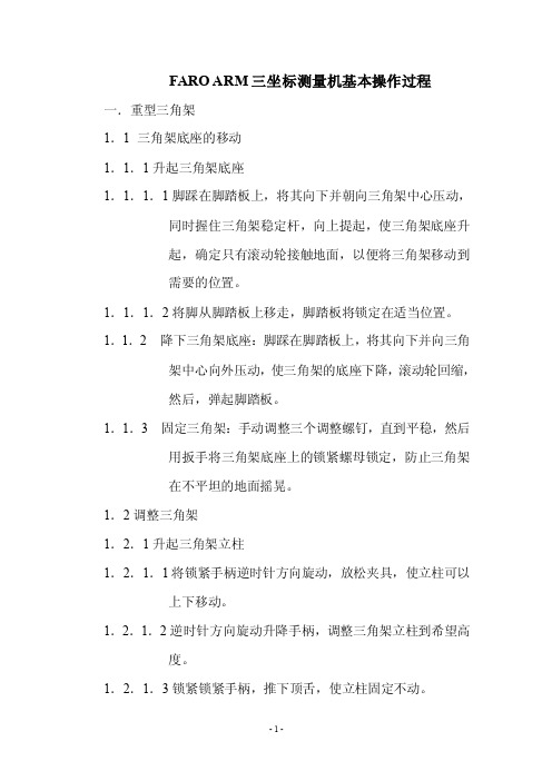
FARO ARM三坐标测量机基本操作过程一.重型三角架1.1三角架底座的移动1.1.1升起三角架底座1.1.1.1脚踩在脚踏板上,将其向下并朝向三角架中心压动,同时握住三角架稳定杆,向上提起,使三角架底座升起,确定只有滚动轮接触地面,以便将三角架移动到需要的位置。
1.1.1.2将脚从脚踏板上移走,脚踏板将锁定在适当位置。
1.1.2 降下三角架底座:脚踩在脚踏板上,将其向下并向三角架中心向外压动,使三角架的底座下降,滚动轮回缩,然后,弹起脚踏板。
1.1.3 固定三角架:手动调整三个调整螺钉,直到平稳,然后用扳手将三角架底座上的锁紧螺母锁定,防止三角架在不平坦的地面摇晃。
1.2调整三角架1.2.1升起三角架立柱1.2.1.1将锁紧手柄逆时针方向旋动,放松夹具,使立柱可以上下移动。
1.2.1.2逆时针方向旋动升降手柄,调整三角架立柱到希望高度。
1.2.1.3锁紧锁紧手柄,推下顶舌,使立柱固定不动。
1.2.2降低三角架立柱1.2.2.1将锁紧手柄逆时针方向旋动,放松夹具,使立柱可以上下移动。
1.2.2.2逆时针方向旋动四方手柄大约1英寸,将顶舌抬起。
1.2.2.3顺时针方向旋动四方手柄,使立柱降低。
1.2.2.4锁紧锁紧手柄,使立柱锁定在固定位置。
二.安装FARO ARM:正确的安装方法是保证测量精度的基础。
2.1将快速安装卡盘安装到三角架底座安装面板上,拧紧固定螺栓。
2.2将FARO ARM的下底座安装到快速安装盘上,并用扳手拧紧。
2.3选择所需用的测头安装到FARO ARM上,注意用力适度,以免损伤螺纹和影响测量精度。
2.4注意:三角架最好安装在水平面上,坡度较大时要防止ARM 坠落摔伤。
ARM暂时不用时要把第2和第6关节相对放置,并用臂固定贴固定好。
三.选择相应的校准器(球校准器或锥校准器),并固定在FARO ARM臂长的1/2-2/3范围处,以备FARO ARM校准之用。
四.连接计算机和FARO ARM4.1将端口锁(加密狗)插入到计算机的USB接口上,以授权CAM2正常运行。


FARO测量
步骤:
1.CATIA文件存为CGR文件
2.翻译:“程序”——“FARO”——“CAD Translate”
3.“Add”——“Translate”——“Close”
4.“File”——“Insert”——“CAD Parts”
矫正探针:“Devices”——“Probes”——“6mm Ball”
1.测量圆球校准FARO(测量三个互相垂直的面,每测量五个点确定一个
面),或导入已校准(矫正)的结果
2.建立坐标系:“Measure”——“Circle”(面三点,孔内壁三点,调整要求
偏差+—0.5,勾取所要保留的,输入孔的坐标值)——测量三个基准孔之后将所测量的结果与理论值合并,检查误差。
3.提取要测量件的面:对销子,“Construct”——“Circle”——
“Normal”,左键在测量面上取三点以建面,然后右键确定输入信息;对
NC-BLOCK,“Construct”——“Plan”——“Normal”,左键在测量面上取三点以建面,然后右键确定输入信息。
测量校准:在所截取的面上进行测量,并根据误差进行调整。

Faro软件的大致使用方法
1.创建新的扫描项目:
第一次启动 SCENE 时,项目选择器将要求您建立缺省项目位置。
如果硬盘驱动器的专用位置上已经存在现有扫描项目,则通常会选取此目录作为缺省项目位置。
稍后您可以在工具--选项--文件夹--项目位置下添加更多缺省项目位置。
使用标准工具栏中的创建新项目按钮或选择文件--新建--项目。
使用项目选择器中的创建新项目按钮。
或者直接将扫描仪扫描的文件拖入软件,处理后要保存时会提示新建项目。
如图:
2.项目历史:
项目历史显示扫描项目的所有修订版本的相关信息。
项目历史是一个强大的工具,它允许您对更改进行跟踪、导出修订版本甚至恢复至特定的修订版本并恢复特定修订版本创建之前所作的所有更改。
3.使用工作区:
文件菜单下的新建--新建工作区命令或双击(扩展名为 .fls)扫描文件新建一个空白工作区。
然后,SCENE 将打开一个新的工作区,其中仅包含当前扫描。
直接拖入文件也可以生成工作区。
在数据导入后要先保存成工作区,以此来保护原始数据不受影响。
如果您使用本地工作区进行工作,您可能需要将它与另一个工作区进行
合并。
要完成此操作,您需要使用文件--导入命令导入其他工作区,然后选择文件扩展名为 .fws 的 FARO 工作区和工作区文件。
4.扫描数据的查看:
对导入工作区的数据点击鼠标右键选择视图选项,可使用快速视图、平面视图、结构视图或三维视图进行查看。
快速视图–用于检查单个扫描的标准扫描视图。
为此,不必加载扫描。
快速视图在几秒钟内就可获得;同时在后台加载扫描数据。
后台加载完成后,便可以操作扫描点。
在此之前,只能进行查看和导航。
平面视图–用于检查单个扫描。
必须加载扫描;如有需要,会自动加载。
如果要对特征点进行选择,必须打开这个视图才可以编辑。
三维视图–三维视图不仅能够显示单个扫描或扫描点云的扫描点,还提供了项目点云或工作区中的所有扫描和对象的组合视图。
如果想卸载该测站的视图,在你想卸载的数据上选择右键—已加载,数据即被卸载。
同理,加载数据也可以这么进行。
5.三维视图下的视图查看操作:
基于观察者的飞行导航模式可模拟三维世界中的飞行活动。
光标的左、右、上和下键可实现向左、向右、向前和向后的移动。
向上翻页键和向下翻页键实现上下移动。
此外,可按 Shift 键加快移动速度。
基于观察者的行走导航模式与飞行模式类似,但局限于 XY 平面,您只能沿着 XY 平面行走。
例如,将移动限制在建筑物楼层时,行走模式就十分有用。
使用基于对象的导航(检查模式)时,看起来似乎是您原地不动,而对象在移动。
旋转中心点(旋转点)位于三维世界中某处。
使用三维视图工具栏中的按钮可自动或手动设置旋转点以扫描点或对象。
平移–在此导航模式中无法进行转动。
将鼠标的移动理解为观察者的移动。
设置旋转点-可以以设置的点做为中心进行旋转。
通过工具--选项--导航可调整移动速度、旋转可变性、鼠标滚轮的行为和
旋转点的设置。
6.点云数据的拼接:
测量大型物体时要对点云数据进行拼接处理。
第一种情况是有设置靶球时的拼接:可以人工拼接,也可以自动拼接。
人工拼接就是人工选取靶球,选择标定靶球。
自动拼接较为简单,选择工具—选项—匹配—匹配球体设置,输入靶球的半径。
然后右键选择操作—正在预处理—预处理扫描,如是初次拼接就把勾上。
勾上以上选项。
点击应用,系统会自动拼接图像。
7.点云数据的删除:
点击,框选所要删除的点,按Delete即可。
一般在Geomagic里删除会比较精确。
8.数据的输出:
右键点击,选择导出—导出扫描点,在子样本选项中可以选择导出的行和列(如:导出3行3列就是9个点变为一个点,数据减少9倍)。
如果要在Geomagic中处理则要在XYZ选项里将包括行列选项去掉。
导出即可。