复合材料板弹簧
- 格式:pdf
- 大小:287.77 KB
- 文档页数:7
复合钢板弹簧的分析与优化Mahmood M. Shokrieh *, Davood Rezaei 复合材料研究实验室,机械工程系,伊朗科技大学,narmak,德黑兰16844,伊朗理论轻型车辆后悬架系统中使用的四片钢板弹簧是用ANSYS V5.4这种软件进行分析的。
有限结果显示应力和挠度的解析解和实验验证。
使用这种钢板弹簧的结果,通过ANSYS设计出了一种由玻璃纤维与环氧树脂复合制成的弹簧并且得到优化。
主要考虑的是弹簧几何的优化。
其主要目的就是获得一种能够无故障地承载静态外力的轻型弹簧。
这个设计的难点就是受力与位移。
结果表明,最佳的弹簧宽度是以双曲线的规律减小,而厚度从弹簧端孔向轴座线性的增加。
比起钢弹簧,优化复合弹簧应力较低,其自然频率较高和弹簧重量在没有端孔情况下降低80%。
2003埃尔塞维尔科技有限公司版权所有。
关键词:钢板弹簧;复合材料;形状优化;有限元;复合接头;自然频率;悬架系统;组合梁1、介绍为了取代金属零件,复合材料在现在汽车工业中得到广泛使用。
关于应用于汽车的复合材料的多篇论文得到发表。
在这里引用了其中的一些论文,重点是那些涉及复合钢板弹簧的论文。
Breadmore [ 1 , 2]研究了汽车复合结构的应用。
Moris[3]集中把复合材料应用到后方的悬挂系统。
Daugherty[ 4]研究了复合钢板弹簧在重型卡车中的应用。
Yu and Kim[ 5]设计并优化了应用于汽车悬挂的双锥形束钢板弹簧。
Corvi[ 6]调查复合梁设计的初步探讨并用它设计了一个复合钢板弹簧。
弹簧是汽车悬挂中关键的一部分,在尽量减少由于道路违规带来垂直振动,影响和颠簸并创造舒适的乘坐方面是必要的。
钢板弹簧,尤其是纵向型的,是一个可靠和持续的元素在汽车悬挂系统中。
这些弹簧通常由钢板叠加而成,长度由下而上逐步变长,使弹簧在中间抵抗弯曲的地方比较厚而在末端与机体相连的地方比较薄。
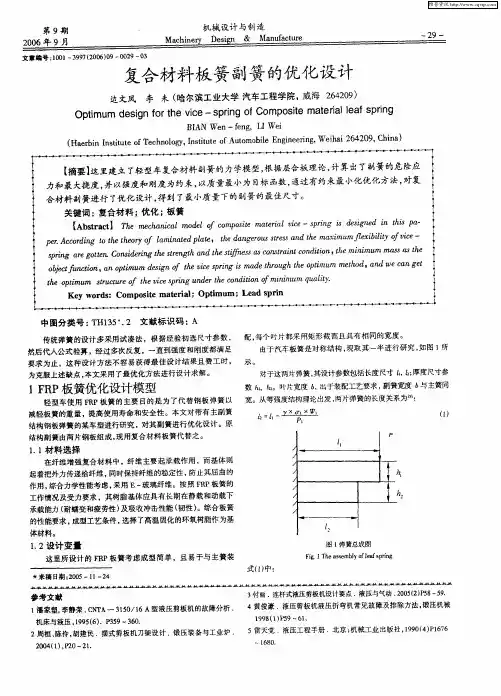
弹簧片应支持如图1所示的各种外部力量,但最重要的任务是抵抗变化的垂直力。
汽车板弹簧材料的选择在汽车制造过程中,板弹簧是一种重要的悬挂系统组件。
它主要的功能是支撑车身重量和减震,同时也对车辆的操控性和乘坐舒适性有着重要的影响。
而正确选择合适的板弹簧材料对于实现这些功能起着至关重要的作用。
在选择板弹簧材料时,需要考虑多个因素。
首先是弹性模量。
弹性模量是衡量材料弹性变形能力的重要参数,高弹性模量的材料能够更好地支撑车身重量和减震。
常用的板弹簧材料有碳钢、合金钢和复合材料。
碳钢弹簧具有良好的强度和刚度,同时价格相对较低,是一种常用的板弹簧材料。
合金钢弹簧由于添加了特定的合金元素,具有更好的强度和刚度,适用于需要更高强度和更小变形的应用场合。
而复合材料弹簧由于具有较高的弹性模量和较小的重量,可以在一定程度上提高车辆的操控性和燃油经济性。
其次是耐腐蚀性。
汽车在实际使用过程中会遇到多种腐蚀介质,如雨水、路面盐碱等。
为了保证弹簧的正常工作和延长使用寿命,板弹簧材料的耐腐蚀性非常重要。
碳钢弹簧通常需要进行防腐处理,如镀锌、热处理等,以提高其耐腐蚀性。
合金钢弹簧由于合金元素的添加,具有较好的耐腐蚀性,较少需要特殊处理。
而复合材料弹簧由于材料本身的特性,具有良好的耐腐蚀性能。
再次是疲劳性能。
板弹簧在使用过程中经历了反复的加载和卸载过程,需要具有较好的疲劳性能以保证长期的可靠工作。
碳钢弹簧由于其良好的延展性和韧性,通常具有较好的疲劳性能。
合金钢弹簧由于强度和硬度较高,疲劳性能也相对较好。
复合材料弹簧由于其材料的特殊性,具有很好的疲劳性能,可以在长时间的使用中保持较好的弹簧特性。
最后是制造成本。
在选择板弹簧材料时,制造成本也是一个需要考虑的因素。
碳钢弹簧由于材料价格相对较低,制造成本也相对较低。
合金钢弹簧由于合金元素的添加,制造成本相对较高。
而复合材料弹簧由于材料的特殊性,制造成本较高。
综上所述,正确选择合适的板弹簧材料对于汽车的悬挂系统性能和使用寿命有着重要的影响。
选择材料时需要综合考虑弹性模量、耐腐蚀性、疲劳性能和制造成本等多个因素,以满足汽车的实际需求。

【技术帖】复合材料板簧设计与开发【摘要】针对于汽车复合材料板簧进⾏产品结构设计、材料选择、⼯艺优化,结合CAE分析仿真计算,掌握板簧铺层设计⽅法。
通过台架试验,研究复合材料板簧测试⽅法,形成相应的技术标准,同时对复合材料板簧进⾏成本分析,为其产业化做铺垫。
主题词:复合材料板簧设计开发1 前⾔⼋⼗年代末,复合材料板簧在美国正式投⼊商业化⽣产,⼴泛应⽤于重型卡车和牵引车上,重量仅为钢材板簧的1/3;德国IFC Composite公司推出⼀种新型板簧来代替奔驰、凌特(Sprinter)、⼤众Crafter车上的传统钢制板簧。
该新型板簧与钢制板簧相⽐,质量减轻40~50%,仅重5.5 kg,疲劳寿命可达20万次以上,⾼于⾦属板簧的16万次。
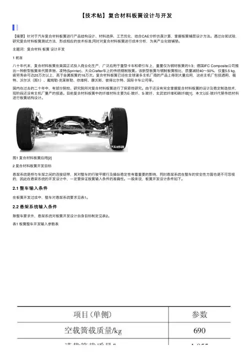
复合材料板簧已经在全球诸多主机⼚商的产品上得到⼤量应⽤,这些主机⼚包括通⽤、福特、沃尔沃(图1)、戴姆勒-克莱斯勒、依维柯、康沃斯、彼得⽐尔特、国际卡车公司等。
国内在过去的⼆⼗年中,有部分院校、研究院所对复合材料板簧进⾏了探索性研究。
由于还没有完全掌握复合材料板簧的设计及稳定制造技术,现阶段还没有主机⼚量产的报道。
⽬前复合材料板簧中的纤维材料主要为E-玻纤、S-玻纤、⽞武岩纤维和碳纤维[1],本⽂以E-玻纤代替传统材料进⾏板簧结构设计。
图1 复合材料板簧应⽤[2]2 复合材料板簧开发⽬标悬架系统是桥与车架之间的连接纽带,其对整车的⾏驶平顺⾏及操纵稳定性有着重要的影响,同时悬架系统在整车的安全性⽅⾯也是不可忽视的,因此在悬架系统的开发设计中,⼀定要保证板簧输⼊条件的准确性。
⼀般来说,板簧开发设计条件如下。
2.1 整车输⼊条件在板簧开发过成中,整车对悬架系统要求见表1。
2.2 悬架系统输⼊条件除整车要求外,悬架系统对板簧开发设计⾃⾝⽬标制定见表2。
表1 板簧整车开发输⼊参数表表2 板簧开发⽬标3 复合材料板簧开发设计3.1 结构设计⽅法复合材料板簧采⽤单⽚等强度设计,保证板簧沿轴线各截⾯具有相同的强度,以此来降低板簧重量。
汽车复合材料板弹簧的有限元分析及性能测试汽车复合材料板弹簧是现代汽车悬挂系统中的一种新型材料弹簧,它由多层玻璃纤维增强环氧树脂层和铝合金层组成。
该材料弹簧具有体积小、重量轻、抗疲劳性能好、寿命长等优点,为汽车行业带来了重大突破。
本文将从有限元分析和性能测试两个方面对汽车复合材料板弹簧进行探讨。
一、有限元分析有限元分析是一种重要的工程计算方法,可以对汽车复合材料板弹簧的力学性能进行数值模拟,以预测材料弹性变形、疲劳寿命、最大承载能力等重要指标。
通过有限元分析模拟,可以更好地理解和优化汽车复合材料板弹簧的设计和制造。
在有限元分析过程中,需要首先建立汽车复合材料板弹簧的三维模型,并对其进行网格化处理。
接着需要根据弹簧的实际工作环境、外载荷和边界条件等因素,建立合适的力学模型。
然后利用有限元软件进行模拟计算,得到板弹簧的应力、应变、位移等物理量分布规律。
最后根据模拟结果进行分析和评估。
在具体的有限元分析中,需要考虑材料的弹性模量、泊松比、热膨胀系数等参数。
还需要考虑板弹簧的几何结构、截面形状、厚度和叠层方式等因素。
这些因素都会对板弹簧的强度、刚度和疲劳寿命等性能产生重要影响。
因此,有限元分析的结果可以为汽车复合材料板弹簧的设计和制造提供重要参考依据。
二、性能测试为了验证有限元分析的结果,需要进行汽车复合材料板弹簧的性能测试。
性能测试可以直接测量弹簧的实际物理量,如位移、应力、应变等,从而检验有限元分析的准确性和信度。
常见的汽车复合材料板弹簧性能测试方法包括三点弯曲试验、循环荷载试验、疲劳寿命试验等。
其中,三点弯曲试验是最基本的试验,可测量板弹簧的弹性模量、屈服强度、极限承载力等力学指标;循环荷载试验可以模拟板弹簧的实际工作环境,测量其疲劳寿命和断裂机理;疲劳寿命试验则可以评价板弹簧在长期疲劳作用下的耐久性和可靠性。
在性能测试中,需要特别注意汽车复合材料板弹簧的热膨胀系数对测试结果的影响。
因为板弹簧由不同的材料复合而成,各层材料的热膨胀系数不一致,容易引起板弹簧在变温作用下的应力和变形。

复合材料板簧在汽车上的应用作者:刘慧杨锁望王晓地范晓轩刘雷雷周震华来源:《新材料产业》2020年第04期节能减排给予汽车工业和研发人员持续的挑战,减轻汽车质量对汽车的发展具有重要的意义。
2012年国务院颁布的《节能与新能源汽车产业发展规划(2012-2020)》指出,到2020年,当年生产的乘用车平均燃料消耗量降至5.0L/100km。
减轻汽车自重,不仅可以降低对原材料的消耗,降低成本,还可以极大地节能减排,同时提高汽车的动力性能。
汽车的轻量化设计已成为当今汽车产业发展的重要研究方向。
现代汽车底盘弹簧的分类主要包括钢制螺旋弹簧和钢板弹簧。
家用汽车主要以螺旋弹簧为主,而卡车、厢式货车等重型汽车主要使用钢板弹簧。
近年来,由于复合材料技术的发展,玻纤增强型复合材料板簧发展成为应用在汽车悬架上的新型轻量化解决方案,其在汽车上的应用主要分纵置和横置2种结构形式。
纵置板簧多用于货车上,结构与传统钢板弹簧相似;横置板簧多用于汽车,对悬架布置影响较大;材料上,由于玻纤增强型板簧材料的各向异性特点,对设计校核也提出了新的挑战。
本文简述了复合材料板簧的应用现状和工艺过程,并以玻纤增强型复合材料板簧为例研究其在汽车上的应用方法和原理,为该技术的研究和应用提供参考。
1复合材料板簧的应用发展、材料和工艺1.1复合材料板簧的发展历程意识到复合材料板簧所能带来的优异性能,越来越多的厂商竞相研制并取得了一定的成果。
目前,传统的钢制板簧正逐渐被复合材料板簧取代。
这一发展大体经历了3个阶段。
第1阶段是1970年以前,为原理性实验探索阶段。
这期间,有大量的应用理论分析文章和阶段性研制报告被发表。
第2阶段是1980年以前,为实用化研制阶段。
伴随塑料工业的发展,这期间纤维增强塑料(Fibergla ss Reinfo rcedPlastics,FRP)研制成功,这种材料不仅耐温、耐磨,而且价格合适。
同时,汽车市场正向小型化和轻型化方向发展,特别是第2次石油危机以后,为了减轻汽车自重、降降油耗,汽车厂商积极投入复合材料板簧的研制,促进了复合材料板簧从理论向实际应用的发展,并成功美国实现FRP板簧在投入应用。
以下资料来自<机械设计手册>:1.板弹簧的结构、特点和类型板弹簧主要用在汽车、拖拉机和铁道车辆中作弹性悬挂装置,起缓冲和减振作用。
也在各种机械中用作为防振装置。
板弹簧具有结构简单,修理方便的特点。
其缺点是质量和体积比较大,单位体积的储能能力较小,多板弹簧的板间摩擦力大,减少了弹性,但对吸收能量和减振是有利的。
2.板弹簧的板料及许用应力目前用于制造板弹簧的材料,应用最广的是:55Si2Mn,60Si2Mn和55SiMnVB等,当板片厚度大于12mm时,采用55SiMnMoV。
板片在热处理后,硬度应达到HRC39~47,并在其凹面进行喷丸处理,以提高使用寿命。
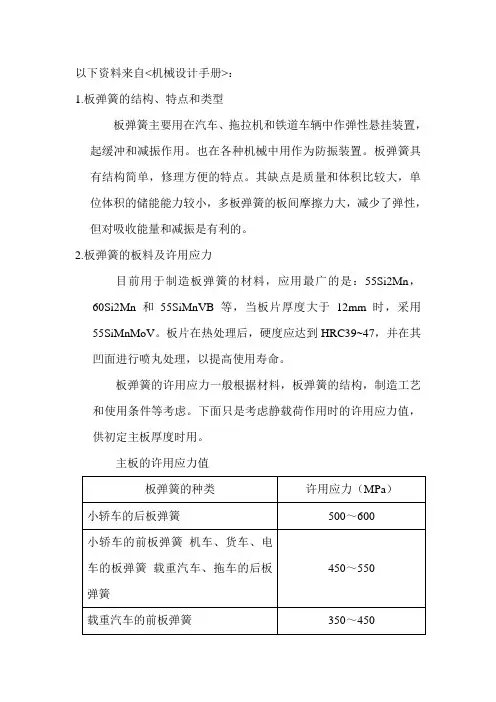
板弹簧的许用应力一般根据材料,板弹簧的结构,制造工艺和使用条件等考虑。
下面只是考虑静载荷作用时的许用应力值,供初定主板厚度时用。
主板的许用应力值缓冲器的板弹簧300~400注:许用应力越大变型的程度也越大,超过极限的变型后恢复的能力就越小。
以下资料来自百度:汽车钢板弹簧汽车钢板弹簧(automobile leaf springs)北方地区又叫“弓子板”一、汽车钢板弹簧作用。
长锥变截面板簧钢板弹簧:由多片不等长和不等曲率的钢板叠合而成。
安装好后两端自然向上弯曲。
当路面对轮子的冲击力传来时,钢板产生变形,起到缓冲、减振的作用,纵向布置时还具有导向传力的作用。
非独立悬挂大多采用钢板弹簧做弹性元件,可省去导向装置和减振器,结构简单。
钢板弹簧是汽车悬架中应用最广泛的一种弹性元件,它是由若干片等宽但不等长(厚度可以相等,也可以不相等)的合金弹簧片组合而成的一根近似等强度的弹性梁。
当钢板弹簧安装在汽车悬架中,所承受的垂直载荷为正向时,各弹簧片都受力变形,有向上拱弯的趋势。
这时,车桥和车架便相互靠近。
当车桥与车架互相远离时,钢板弹簧所受的正向垂直载荷和变形便逐渐减小,有时甚至会反向。
重型车板簧主片卷耳受力严重,是薄弱处,为改善主片卷耳的受力情况,常将第二片末端也弯成卷耳,包在主片卷耳的外面,称为包耳。
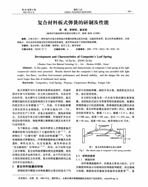
2021年(第43卷)第6期汽车工程Automotive Engineering2021(Vol.43)No.6复合材料板簧的迟滞特性建模与试验研究*刘鹤龙1,史文库1,高蕊2,陈志勇1,陈晃2,孙云龙3(1.吉林大学,汽车仿真与控制国家重点实验室,长春130022;2.中国重汽集团汽车研究总院,济南250100;3.哈尔滨玻璃钢研究院有限公司,哈尔滨150036)[摘要]运用Bouc⁃Wen摩擦学理论建立了复合材料板簧的迟滞特性模型,根据台架试验测得的动态力-位移曲线,利用改进的乌鸦搜索算法(MCSA)进行了模型的参数辨识。
仿真结果与试验结果吻合较好,表明该模型能准确预测复合材料板簧的迟滞特性。
建立考虑复合材料板簧迟滞特性的整车7自由度动力学模型,分析了在随机路面激励下,复合材料板簧迟滞特性对整车动态响应的影响。
结果表明,复合材料板簧的迟滞特性使簧载质量的质心加速度增加,板簧的回复力增大,而悬架的动挠度减小。
该研究为复合材料板簧的整车匹配和精细化动力学建模提供参考。
关键词:复合材料板簧;迟滞特性;平顺性;Bouc⁃Wen模型;乌鸦搜索算法Modeling and Experimental Study on Hysteresis Characteristic ofComposite Leaf SpringsLiu Helong1,Shi Wenku1,Gao Rui2,Chen Zhiyong1,Chen Huang2&Sun Yunlong31.Jilin University,State Key Laboratory of Automotive Simulation and Control,Changchun130022;2.Automotive Research Institute of China National Heavy Duty Truck Group Co.,Ltd.,Jinan250100;3.Harbin FRP Institute Co.,Ltd.,Harbin150036[Abstract]Bouc⁃Wen tribology theory is applied to the setting up of the hysteresis characteristic model of composite leaf springs,and according to the dynamic force⁃displacement curves obtained by bench test,the model parameters are identified by using the modified crow search algorithm(MCSA).The simulation results well agree with the test ones,showing that the model can accurately predict the hysteresis characteristic of composite leaf spring.A seven DOF vehicle dynamic model is established with consideration of the hysteresis characteristic of com⁃posite leaf spring,and the influence of the hysteresis characteristic of composite leaf springs on the dynamic re⁃sponse of vehicle under random road excitation is analyzed.The results indicate that the hysteresis characteristic of composite leaf spring increases the mass⁃center acceleration of sprung mass and the restoring force of leaf spring,and reduces the dynamic deflection of suspension.This study provides a reference for the vehicle matching and the refined dynamic modeling of composite leaf springs.Keywords:composite leaf spring;hysteresis characteristic;ride comfort;Bouc⁃Wen model;crow search algorithm前言随着能源短缺的问题日益凸显和新能源汽车对续航里程的要求逐渐提高,汽车轻量化技术的发展得到了广泛的关注。
专利名称:横置复合材料板簧悬架结构专利类型:实用新型专利
发明人:刘雪品,陈茂远,伊江
申请号:CN201720867824.8
申请日:20170717
公开号:CN206900123U
公开日:
20180119
专利内容由知识产权出版社提供
摘要:本实用新型为一种横置复合材料板簧悬架结构,包括主车架下方两侧分别设置的车桥连接结构,两个车桥连接结构用于连接车桥与主车架、且两个车桥连接结构的长度方向与主车架的纵向呈平行设置,两个车桥连接结构与主车架之间均设置有减震结构;两个车桥连接结构的相对一端之间顶抵设置有能沿主车架的横向伸缩的、且能与主车架连接的横置复合材料板簧结构。
该悬架结构克服现有技术中存在的悬架结构中板簧纵向安装受底盘空间限制和空气弹簧成本高、使用寿命短、存在安全隐患等问题,充分利用复合材料板簧比重轻、吸能性好等特性,实现了悬架结构占用底盘空间小、使用寿命长的目的,有效降低成本,提高安全性。
申请人:北京嘉朋机械有限责任公司
地址:102200 北京市昌平区马池口镇白浮村5号
国籍:CN
代理机构:北京三友知识产权代理有限公司
代理人:王春光
更多信息请下载全文后查看。
复合材料板簧
复合材料板簧是一种由多种材料组合而成的弹簧,它具有轻质、高强度、耐腐
蚀等特点,因此在工程领域中得到了广泛的应用。
复合材料板簧通常由玻璃纤维、碳纤维、环氧树脂等材料组成,其制造工艺复杂,但是可以根据需要进行定制,以满足不同工程项目的需求。
首先,复合材料板簧具有较高的强度和刚度。
由于其材料的特性,复合材料板
簧可以承受较大的负荷,同时保持稳定的形状,不易变形或断裂。
这使得复合材料板簧在需要承受较大压力或拉力的工程项目中得到了广泛的应用,例如航空航天领域的飞机起落架、汽车工业中的悬挂系统等。
其次,复合材料板簧具有较轻的重量。
相比于传统的金属板簧,复合材料板簧
的重量更轻,这使得它可以在不增加额外负担的情况下,为工程项目提供更大的弹性支撑。
在需要减轻整体重量的工程项目中,复合材料板簧可以发挥其独特的优势,例如在航空航天领域的航天器结构中,复合材料板簧可以减轻整体重量,提高载荷能力。
此外,复合材料板簧具有良好的耐腐蚀性能。
由于其主要材料为玻璃纤维、碳
纤维等非金属材料,复合材料板簧不易受到腐蚀的影响,可以在恶劣的环境条件下长期稳定运行。
这使得复合材料板簧在海洋工程、化工设备等领域得到了广泛的应用,可以有效延长设备的使用寿命,降低维护成本。
综上所述,复合材料板簧作为一种新型的弹簧结构,在工程领域中具有重要的
应用前景。
它的轻质、高强度、耐腐蚀等特点,使得它可以满足不同工程项目的需求,为工程项目提供更可靠的支撑和保障。
随着材料科学技术的不断发展,相信复合材料板簧将会在更多领域展现出其独特的优势,为工程领域的发展做出更大的贡献。
板弹簧原理
弹簧是一种能够储存和释放能量的装置,它由一根金属线圈组成。
板弹簧是其中一种常见的类型,它由一根金属板(通常是钢板)制成,形状呈矩形或方形。
板弹簧的工作原理基于胡克定律,即弹簧的变形与其所受到的力成正比。
当外力作用于板弹簧上时,弹簧会发生弹性变形,即形成弯曲或弯折。
当外力消失时,弹簧会恢复原状。
弹簧的弹性是由其材料特性和结构决定的。
金属板的选择通常是根据所需的弹性程度和应力承受能力来确定的。
较薄的板材具有较高的弹性,能够产生更大的变形;而较厚的板材则更适合承受高强度的力。
此外,板弹簧常常被设计成多层叠加的结构,以增加其弹性和承载能力。
板弹簧常用于许多机械设备中,如悬挂系统、减震器和传感器。
在悬挂系统中,板弹簧可以承受车辆的重量并提供支撑和缓冲的功能,从而使行驶更加平稳。
在减震器中,板弹簧可以吸收道路颠簸产生的冲击力,减少车辆的震动。
在传感器中,板弹簧可以测量物体的压力或重量,通过测量弹簧的变形来确定所施加的力的大小。
总之,板弹簧利用材料的弹性特性,可以储存和释放能量,广泛应用于各种机械设备中。
其工作原理简单而有效,使其成为许多工程领域中不可或缺的元件之一。
复合弹簧详细参数复合弹簧--振动筛专用弹簧复合弹簧全称为橡胶金属螺旋复合弹簧,是在金属螺旋弹簧周围包裹一层橡胶材料复合硫化而成的一种弹簧。
复合弹簧是由金属螺旋弹簧和橡胶复合为一体的弹性体,该产品集金属弹簧和橡胶弹簧的优点于一体,克服两者的缺点,使用性能稳定、能承受载荷以及较大变形量、同时具有隔振降噪效果好、工作平稳共振区时间短等优点。
复合弹簧图纸:复合弹簧三维图:复合弹簧优点:具有TT橡胶弹簧的非线性和结构阻尼的特性,又具有TT金属螺旋弹簧大变形和承载能力大的特性,其稳定性和承载能力优于TT橡胶弹簧,结构比空气弹簧简单,固有频率虽然高于TT金属弹簧但低于TT 橡胶弹簧。
1、结构独特、维护方便。
TT复合弹簧2、可替代金属螺旋弹簧,并有优良的阻尼效果。
3、可替代防振橡胶弹簧,但能承受很大的载荷。
4、可代替不锈钢弹簧耐潮湿、耐腐蚀使用寿命长。
5、适于做大载荷、低频隔振系统的隔振弹簧6、与金属碰撞不产生火花、适于易燃、易爆环境工作。
7、具有类似空气弹簧的工作特性曲线,但结构简单、无气体泄露。
复合弹簧参数:规格D×H×d(mm)外径D(mm)内径d(mm)自由高度H(mm)工作变形量FV(cm)刚度KL(kg/cm)静态载荷(kg)Ф90×150×Ф38 90 38 150 2 150-350 300-700 Ф90×150×Ф40 90 40 150 2 150-350 300-700 Ф148×260×Ф80 148 80 260 3 180-600 500-1800 Ф150×200×Ф80 150 80 200 2 180-500 360-1000Ф150×220×Ф70 150 70 220 2.2 180-550 400-1210 Ф150×250×Ф80 150 80 250 3 180-600 500-1800 Ф150×265×Ф80 150 80 265 3 180-600 500-1800 Ф150×265×Ф92 150 92 265 3 180-600 500-1800 Ф150×270×Ф80 150 80 270 2.7 180-600 500-1800 Ф150×400×Ф50 150 50 400 3 180-800 500-1800 Ф155×290×Ф60 155 60 290 3 220-660 660-2000 Ф155×290×Ф62 155 62 290 3 220-660 660-2000 Ф155×290×Ф75 155 75 290 3 220-660 660-2000 Ф155×330×Ф60 155 60 330 3 220-660 660-2000 Ф160×236×Ф94 160 94 236 2-3 250-1000 750-3000 Ф160×240×Ф94 160 94 240 2-3 250-1000 750-3000 Ф160×250×Ф90 160 90 250 3 180-600 500-1800 Ф160×290×Ф62 160 62 290 3 240-660 700-2000 Ф180×210×Ф50 180 50 210 2.5 240-660 600-1650Ф180×270×Ф80 180 80 270 3 300-1000 900-3000 Ф180×290×Ф62 180 62 290 3 500-1000 2000-4000 Ф180×290×Ф80 180 80 290 3 300-1000 900-3000 Ф200×335×Ф80 200 80 335 3 300-1500 900-4500非标复合弹簧参数:Ф75×130×Ф30 7530 130 1.3 150-330 195-429 Ф105×130×Ф60 105 60 130 1.3 150-350 195-429 Ф150×150×Ф50 150 50 150 1.5 220-500 221-750 Ф155×280×Ф55 155 55 280 2.8 220-660 616-1848 Ф180×210×Ф50 180 50 210 2.1 250-1300 540-2730 Ф180×230×Ф80 180 80 230 2.3 250-1500 575-3450 Ф135×261×Ф75 内外双135 75 261 2.61 220-600 574-1566 面罗纹Ф153×268×Ф80 内外双153 80 268 2.68 220-600 574-1566 面罗纹Ф85×120×Ф35 85 35 120 1.2 150-330 180-396 Ф90×150×Ф40 90 40 150 1.5 150-350 225-525 Ф90×150×Ф50 90 50 150 1.5 150-350 225-525 Ф90×80(实心)90 80 0.8 150-280 120-224 Ф100×130(实心)100 130 1.3 150-330 195-429 Ф100×160(实心)100 160 1.6 150-350 528-560 Ф110×130×Ф70 110 70 130 1.3 150-300 195-390 Ф110×130×Ф45 110 45 130 1.3 150-300 195-390 Ф110×180×Ф45 110 45 180 1.8 150-350 270-630 Ф150×140×Ф50 150 50 140 1.4 180-350 252-490 Ф150×225×Ф80葫芦150 80 225 2.25 180-500 405-1125 Ф125×190×Ф62葫芦125 62 190 1.9 150-350 285-665 Ф150×250×Ф62 150 62 250 2.5 180-550 450-1375 Ф150×250×Ф94 150 94 250 2.5 180-600 450-1500 Ф150×265×Ф62 150 62 265 2.65 180-600 477-1590 Ф150×270×Ф62 150 62 270 2.7 180-600 486-1620 Ф155×220×Ф80 155 62 220 2.2 180-550 396-1210 Ф155×230×Ф80 155 80 230 2.3 180-550 414-1265 Ф155×230×Ф62 155 62 230 2.3 180-550 414-1265 Ф155×180×Ф95 155 95 180 1.8 180-500 324-720 Ф155×190×Ф95 155 95 190 1.9 180-500 342-950 Ф155×200×Ф95 155 95 200 2 180-550 360-1100 Ф155×210×Ф95 155 95 210 2.1 180-550 378-1155 Ф155×180×Ф38 155 38 180 2 180-550 360-1100 Ф160×200×Ф80 160 80 200 2 250-800 500-1600 Ф160×200×Ф94 160 94 200 2 250-800 500-1600Ф160×240×Ф80 160 80 240 2.4 250-1000 600-2400 Ф160×220×Ф105 160 105 220 2.2 250-800 550-1760 Ф160×210×Ф105 160 105 210 2.1 250-800 525-1680 Ф160×182×Ф62 160 62 182 1.82 250-1000 455-1820 Ф160×220×Ф62 160 62 220 2.2 250-1000 550-2200Ф155×280×Ф62 155 62 280 3 220-660 660-1980 Ф160×230×Ф40 160 40 230 2.3 250-1300 575-2990 Ф160×240×Ф62 160 62 240 2.4 250-1300 600-3120 Ф160×210×Ф94 160 94 210 2.1 250-1200 525-2520 Ф160×180×Ф40 160 40 180 1.8 250-1000 450-1800 Ф160×200×Ф62 160 62 200 2 250-1100 500-2200 Ф180×110×Ф90 180 90 110 1.1 220-1000 242-1100 Ф180×110×Ф65 180 65 110 1.1 220-1000 242-1100 Ф180×110(实心)180 110 1.1 220-1300 242-1430 Ф180×110×Ф105 180 105 110 1.1 220-1000 242-1100 Ф180×180×Ф40 180 40 180 1.8 250-2000 450-3600 Ф180×200×Ф70 180 70 200 2 250-1500 500-3000 Ф180×200×Ф60 180 60 200 2 250-1500 500-3000 Ф180×255×Ф70 180 70 255 2.5 250-1500 625-3750 Ф180×280×Ф80 180 80 280 2.8 250-1500 700-4200 Ф180×280×Ф62 180 62 280 2.8 250-1800 700-5040 Ф180×300×Ф80 180 80 300 3 250-1500 750-4500 Ф180×290×Ф80 180 80 290 2.9 250-1500 725-4350 Ф180×280×Ф80 180 80 280 2.8 250-1500 700-4200 Ф180×280×Ф62 180 62 280 2.8 250-1800 700-5040 Ф180×270×Ф62 180 62 270 2.7 250-1500 675-4050 Ф180×300×Ф80 180 80 300 3 250-1800 750-5400 Ф200×250×Ф60 200 60 250 2.5 300-2000 750-5000 Ф250×220×Ф90 250 90 220 2.2 400-2500 880-5500 Ф250×250×Ф90 250 90 250 2.5 500-2500 1250-6250 复合弹簧应用范围:广泛适用于矿山、冶金、煤炭等行业的大型振动机械设备。
The Analysis of Composite Leaf Springby Finite Element Methodand Experimental MeasurementsJiashi Wang,Zaike Li and Qibin JiangAbstract The automobile industry has shown increased interest in the replacement of steel spring with E-Glass/Epoxy composite leaf spring due to the higher strength-to-weight ratio,superior fatigue strength and excellent corrosion resistance.In this work the composite leaf spring with the rectangular cross section designed for the commercial vehicle was analyzed by using thefinite element software ABAQUS, and the experimental tests had been conducted to confirm thefinite element analysis results.In thefinite element analysis,the stress analysis and the spring rate computation have been conducted for the composite leaf spring subjected to the full load15,000N.The maximum compressive stress is309.1MPa at the middle of the composite leaf spring,and the safe factor can reach to2.6comparing with the material compressive strength of E-Glass/Epoxy800MPa.The spring rate com-puted from ABAQUS is160N/mm,and the maximum load capacity of the composite leaf spring is approximately34,000N.The measurements of the spring rate and the maximum load capacity were conducted on the composite leaf spring fabricated with the hot molding process method,and they are157.5N/mm and 34,280N paring the results obtained from thefinite element analysis with the experimental measurements,it can be seen that the errors are 1.56%for the spring rate and0.82%for the maximum capacity load,and the main performances of fabricated composite leaf spring have the good agreement with the designed requirements.Keywords Composite materialÁLeaf springÁFinite element analysisÁSpring rateÁMaximum load capacityF2012-E07-004J.Wang(&)ÁZ.LiÁQ.JiangZhuzhou Times New Material Technology Co.Ltd.,Zhuzhou,Chinae-mail:wangjiashi@SAE-China and FISITA(eds.),Proceedings of the FISITA2012World823 Automotive Congress,Lecture Notes in Electrical Engineering195,DOI:10.1007/978-3-642-33835-9_74,ÓSpringer-Verlag Berlin Heidelberg2013824J.Wang et al. 1IntroductionIn order to meet the needs of natural resources and economize energy,weight reduction has been the main focus of automobile manufacturer in recent years[1]. Weight reduction can be achieved primarily by the introduction of better material, design optimization and better manufacturing processes.The suspension leaf spring is one of the potential items for weight reduction in automobile.Because of the higher strength-to-weight ratio,superior fatigue strength and excellent corro-sion resistance,thefiber reinforce plastics(FRP)has shown increased interest in the replacement of steel spring[2].When the spring is made of FRP,such as E-Glass/Epoxy,the weight of the spring can reduce60–70%,which can leads to reduction of the unsprung weight.The elements whose weight is not transmitted to the suspension spring are called the unsprung elements of the automobile,include wheel assembly,axles,and part of the weight of suspension spring and shock absorbers[3].The reduction of the unsprung weight could help in achieving the vehicle with improved riding qualities and increased the fuel efficiency.Therefore, the using of composite leaf spring not only leads to the weight reduction,but also improves the riding qualities.Some works have been conducted with emphasis on the design and application of composite leaf spring,and part of them are reviewed here.Breadmore intro-duced the application of composite structures for automobiles[4,5].Moris con-centrated on using composites in the rear suspension system[6].Yu and Kim[2] designed and optimized a double tapered beam for automotive suspension leaf spring.Corvi[7]investigated a preliminary approach to composite beam design and used it for a composite leaf spring.Rajendran and Vijayarangan developed the genetic algorithms for the design optimization of light weight vehicle composite leaf spring[8],and Shiva Shankar and Vijayarangan[1]investigated the light weight vehicle composite leaf spring concentrated on the end joint analysis and testing.However,there is the limitation for the above research that the designed composite leaf spring is used for the light weight vehicle with static full load below10,000N for one spring.Nowadays,with the development of the auto-mobile industrials,the composite leaf spring with more load-bearing is needed. Meanwhile,the structure,material and the fabricate process are all important. Therefore,it is necessary to investigate the composite leaf spring from simulation and experimental test,as well as verify the effectiveness and safety for the heavier load-bearing composite leaf spring.In this paper the composite leaf spring with rectangle cross section that the constant thickness and width is28980mm is designed for the Commercial vehicle with15,000N full load for one spring.Thefinite element(FE)method is used for the analysis of stress state,computation of numerical spring rate and the maximum load capacity.Meantime,for the validity of the designed spring,the experiment is conducted on the composite leaf spring fabricated by the hot molding process.The measured spring rate and the maximum load capacity arecompared with the FE analysis results.This work develops the application of the composite leaf spring for the automobile industrial.2FE Model of the Composite Leaf SpringAccording to the working and assembly conditions and considering the facility of mass production,the mono spring with constant rectangle cross section is employed for the Commercial vehicle.The geometry structure of the spring can be described as follow.The constant thickness and width is 28980mm,the total length is 1,300mm,the arc radius is 1,080mm.Besides,the full loading is 15,000N,and the designed spring rate is 160N/mm.The 3-D structure can be obtained in the ABAQUS software as shown in Fig.1,and the model is meshed with C3D8I [9]as shown in Fig.2.The dimension of the elements is approxi-mately 5mm,and there are 20,000elements.Because the composite leaf spring is mainly subjected to the moment loading,and the tensile and compressive bending stress is along the longitudinal direction.Therefore,the unidirectional fiber glass is selected to be laid up along the longitudinal direction of the spring,and the material properties of the E-Glass/Epoxy are listed in Table 1.3FE Analysis of the Composite Leaf SpringAccording to the loading condition,the full load 15,000N is applied at the middle of the composite leaf spring,and the stress along the longitudinal direction can be obtained in Fig.3.It can be seen that the maximum stress is at the middle location,compressive stress for the outer surface and tensile stress for the inner surface.Meanwhile,the absolute value of the inner surface stress is larger than the one of the outer surface,which may be due to that the composite leaf spring is the curved beam [10].According to the material properties as given in Table 1,the com-pressive strength of composite material is smaller than tensile strength,so the verify of the stress strength should be based on the compressive strength.The Fig.1The 3-D structure ofcomposite leaf spring The Analysis of Composite Leaf Spring825maximum compressive stress is 309.1MPa at the middle of the composite leaf spring as shown in bining the compressive strength in Table 1and the compressive stress in Fig 3,it can be calculated that the safety factor is 2.6.Spring rate is an important parameter for the spring assembled in the vehicle suspension,and it can be computed from the FE analysis as described as follow.During the FE analysis,the variables such as the applied load and the displacement of the composite leaf spring can be recorded,and the load–displacement curvecan Fig.2Finite element mesh of the composite leaf springTable 1Material properties of E-glass/epoxyPropertiesValue Tensile modulus along X direction (Ex),MPa6,530Tensile modulus along Y direction (Ey),MPa45,000Tensile modulus along Z direction (Ez),MPa6,530Tensile strength,MPa1,100Compressive strength,MPa800Shear modulus along XY direction (Gxy),MPa2,433Shear modulus along YZ direction (Gyz),MPa2,433Shear modulus along ZX direction (Gzx),MPa1,698Poisson ratio along XY direction (NUxy)0.217Poisson ratio along YZ-direction (NUxy)0.217Poisson ratio along ZX-direction (NUxy)0.366Fig.3The stress contouralong the longitudinaldirection of the compositeleaf spring subjected to15,000N826J.Wang et al.be plotted in Fig 4.It can be seen that the slope is almost constant during the analysis process,and the relationship of the load and the displacement can be fitted as the linear function by the origin softwarey ¼160x þ59:6ð1Þwhere x and y represent the displacement and load respectively,and 160should be the spring rate.The second part 59.6should be the deviation which is introduce by the FE simulation and the function fitting.The error can be calculated as 59.6/15,0009100%=0.40%,and it can be neglect in the engineer application.The maximum load capacity is another important parameter for application of the composite leaf spring.Theoretically,when the maximum compressive stress of the composite leaf spring is equal to the compressive strength,the spring will be fractured,and the load should be the maximum load capacity.During the FE analysis,the maximum load is set from 20,000to 70,000N,and the increasing step is set as 2,000N.When the load is increased to 34,000N,the stress state of the composite leaf spring can be obtained as shown in Fig.5.The maximum compressive stress is 819.0MPa,which is just larger than the stress strength 800MPa.Therefore,it is suggested that 34,000is the maximum load capacity of the composite leaf spring.4Experimental TestingThe designed composite leaf spring had been fabricated with the hot molding process method,and the three-point bending experiment is conducted to measure the spring rate.The composite leaf spring is loaded from zero to the prescribed maximum load 15,000N and back to zero with loading speed 200N/s.After five cycles,the load–displacement curves can be obtained as given in Fig.6,and five spring rates were computed from the curves,listed as 160.2,154.9,156.2,157.0Fig.4The load–displacement curve of thecomposite leaf springobtained from ABAQUS The Analysis of Composite Leaf Spring827and 159.2N/mm.The averaged value is computed and taken as the final spring rate,which is 157.5N/paring the experimental results with the value 160N/mm obtained from FE analysis in Sect.3,the error is 1.56%,and they have the good agreement.After the measurement of the spring rate,the maximum load is modified as 70,000N,which is about two times of the maximum load capacity theoretically.The loading speed is set as 200N/s,and the loading process is stopped automatically when the composite leaf spring is fractured.The recorded load–displacement curve is obtained as shown in Fig.7,and the maximum load capacity can be extracted from the curve,which is 34,paring the experimental result with the value 34,000N computed by ABAQUS,the error is 0.82%.Fig.5The stress contouralong the longitudinaldirection of the compositeleaf spring as the maximumcompressive stress close tothe compressivestrength Fig.6The load–displacement curves of thecomposite leaf springobtained from theexperimental tests828J.Wang et al.5ConclusionsThe designed composite leaf spring for the commercial vehicles is analyzed by the FE analysis and experimental test.In the FE analysis,the spring rate and the max-imum load capacity are computed by ABAQUS software,and they are 160N/mm and 34,000N respectively.In the experimental tests,the three-point bending experiments of composite leaf spring fabricated with the hot molding process are conducted,and the tested spring rate and maximum load capacity are 157.5N/mm and 34,paring the results obtained from the FE analysis with the experimental tests,it can be seen that the error is 1.56%for the spring rate and 0.82%for the maximum capacity load,and the main performances of fabricated composite leaf spring meet the designed requirements.In this work the delamination damage between the layers in the composite leaf spring is not considered,which will be investigated in the next step.References1.Shiva Shankar GS,Vijayarangan S (2006)Mater Sci 12:220–2252.Yu WJ,Kim HC (1988)Comp Struct 9:279–3003.Tanabe K,Seino T,Kajio Y (1982)SAE 820403:1628–16344.Beardmore P,Johnson CF (1986)Comp Sci Technol 26:251–2815.Beardmore P (1986)Comp Struct 5:163–1766.Morris CJ (1986)Comp Struct 5:233–2427.Corvi A (1990)Comp Struct 16:259–2758.Rajendran I,Vijayarangan S (2001)Comp Struct 79:1121–11299.Simulia (2007)Abaqus user’s manual,Abaqus Version 6.7.1.Dassault Systemes 10.Hibbeler RC (2010)Mechanics of material.Pearson Education Publications,NewJersey Fig.7The maximum loadcapacity test of the compositeleaf spring The Analysis of Composite Leaf Spring829。