C1控制器使用说明书
- 格式:doc
- 大小:4.81 MB
- 文档页数:7
![门禁C102-B[1]](https://uimg.taocdn.com/08776fbe1a37f111f1855b27.webp)
第1页 第2页C102-B 门禁一体机 使 用 说 明 书产品特性:工作电压:DC12V 开锁电流:〈1000mA 静态电流:〈60mA存储容量:250个标准用户 读卡距离:5~15cm 用户卡类型:EM 卡工作温度:-10°C ~70°C 工作湿度:10%~90%尺 寸:117 x117x21mm安装说明:卸下固定面板与底版的十字螺丝,取下底版,使用随机配备的胶塞和螺钉将底版安装在预控制出入口的入口侧墙壁。
请注意一体机的上下方向。
C102-B 门禁一体机系统接线图:C102-B 接线图( 1 )C102-B 接线图( 2)注意:上电前必需确认电源电压(DC12V )和电源的正负极性!说明:防撬报警开关在电路板右下角,闭合禁声,弹开蜂鸣器连续短鸣报警。
具体操作说明:一、 门禁控制器一体机初始化方法: 1. 关闭电源,J6的第2脚和第3脚连接。
2. 接通电源,蜂鸣器连续短续鸣响报警,POWER (红)灯、OK (绿)灯、MODE (橙)灯齐闪烁。
3. 断电,再接通电源,POWER (红)灯、OK (绿)灯、MODE (橙)灯齐闪烁。
等待J6的开关转换。
4. J6的2、3脚断开,1、2脚接通。
5. 门禁一体机初始化完成,蜂鸣器鸣响一声,门禁一体机进入用户使用状态。
说明:初始化操作仅修改一体机系统密码为缺省密码12345(即为出厂默认密码),其它数据不会被删除。
二、 继电器输出设置方法: 1、 PUSH1为继电器干触点输出。
2、 J1的NO 脚连接,PUSH1、GND 常开(继电器动作时,PUSH1、GND 接通)。
3、 J1的NC 脚连接,PUSH1、GND 常闭(继电器动作时,PUSH1、GND 断开)。
三、 门禁一体机编程方法: 1.“#”键:功能键,进入编程模式(1)按“#”字键,POWER (红)灯、OK (绿)灯、MODE (橙)灯齐闪亮。
(2)输入5位系统密码,蜂鸣器鸣响一声,POWER (红)灯和MODE (橙)灯亮、OK (绿)灯熄灭,门禁一体机进入系统编程状态。
CPS-20C1恒压供水控制器应用指南第一章对控制器的补充说明第1节概述CPS-20C1系列控制器是目前CPS系列恒压供水控制器产品之中功能最全,最强大的控制器。
此系列控制器适用于最多有6台主泵加1台附属小泵的供水系统。
所有主泵可设计成变频循环软启动的工作方式,也可设计成1台变频泵加5台工频定量泵,再加1台附属小泵的工作方式。
当然,少于此数目的供水系统也可使用此系列的控制器进行控制。
20C1系列控制器内部控制逻辑及控制算法均采用先进的现代控制理论进行设计,PID 参数免调试,所以用户使用起来,会感觉非常方便,而且供水系统的精度高,系统响应速度快,稳定性好。
除此之外,20C1系列控制器还有很多优点,诸如定时开关机,定时换泵功能,定量泵、变量泵自动巡检功能,故障自动诊断,避免频繁切换水泵等优点。
具体详细介绍,请参阅20C1控制器的说明书,在此就不再详细介绍了。
第2节四种型号20C1控制器的说明CPS-20C1控制器共有4种型号,即标准型(S型)和消防专用型。
其中消防专用型又根据消防泵的正常工作方式和巡检方式分为3种,包括消防泵定量工作,工频巡检(DD)型;消防泵变量工作,变频巡检(BB)型;消防泵定量工作,变频巡检(DB)型三种。
这里的定量和变量是指工频和变频的意思。
4种型号的控制器端子接线和参数代码完全相同,只是工作方式不同。
用户可自己检查控制器的型号,具体操作方法是:将控制器的键盘锁定开关拨至LOCK 位置,然后按下功能键(FUNC),通过面板下排数码管所显示的内容判断控制器的型号。
其中,“1 S-S”为S型,“2 b-b”为BB型,“3 d-d”为DD型,“4 d-b”为DB型。
自2000年7月以后的产品有此项功能,在此之前的产品无此功能。
以前产品的性能并没有差别。
敬请广大用户放心使用。
对这四种型号的控制器的工作方式的说明如下:1.标准型(S型)。
标准型控制器用于一般的生活供水系统,任何一台水泵可设置为变量泵“b”或定量泵“d”。
3.运行工况界面运行工况里包含了配电电压、电流、功率因数、功率、电压各次谐波、电流各次谐波等各电参数的数值显示,以及测控仪与智能电容器的通信状况,通过“或”键切换界面查看各电参数以及测控仪与智能电容器的通信状况,按“”键返回到主菜单界面。
以下细分界面依次对各项进行介绍:(1)配电三相功率因数、电压、电流界面在使用过程中若出现过补偿或配电电流接线接反,则在上述界面中功率因数数值前显示‘-’,例如A相功率因数显示‘-0.960’,表示此时A相电容已过补偿或A相配电电流方向接反。
在使用过程中若出现过压或欠压现象,在上述界面中电压反显显示,例如A相电压显示“”,表示此时A相电压已超过设定过压值。
(2)有功、无功、电容电流界面P(KW) :实时的有功功率;Q(Kvar):系统当前过补偿或欠补偿的无功数值;C-I(A) :实时的电容器电流值。
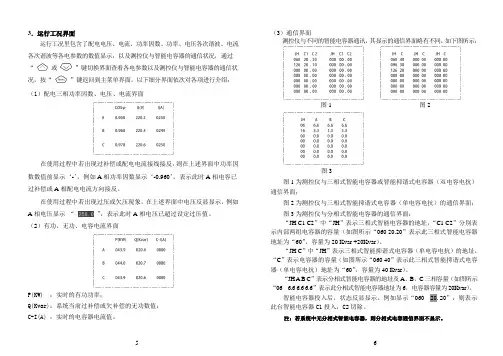
(3)通信界面测控仪与不同的智能电容器通讯,其显示的通信界面略有不同,如下图所示:图1 图2图3图1为测控仪与三相式智能电容器或智能抑谐式电容器(双电容电抗)通信界面;图2为测控仪与三相式智能抑谐式电容器(单电容电抗)的通信界面;图3为测控仪与分相式智能电容器的通信界面;“JH C1 C2”中“JH”表示三相式智能电容器的地址,“C1 C2”分别表示内部两组电容器的容量(如图所示“060 20.20”表示此三相式智能电容器地址为“60”,容量为20 Kvar +20Kvar)。
“JH C”中“JH”表示三相式智能抑谐式电容器(单电容电抗)的地址,“C”表示电容器的容量(如图所示“060 40”表示此三相式智能抑谐式电容器(单电容电抗)地址为“60”,容量为40 Kvar)。
“JH A B C”表示分相式智能电容器的地址及A、B、C三相容量(如图所示“06 6.6 6.6 6.6”表示此分相式智能电容器地址为6,电容器容量为20Kvar)。
智能电容器投入后,状态反显显示。
csac1控制器说明书摘要:一、引言二、CSAC1控制器简介1.产品概述2.功能特点三、CSAC1控制器应用领域1.工业自动化2.智能家居3.医疗设备四、CSAC1控制器技术参数1.硬件配置2.软件配置3.通信接口五、CSAC1控制器操作方法1.系统安装2.参数设置3.运行与维护六、CSAC1控制器与其他控制器的比较七、CSAC1控制器售后服务与支持八、结语正文:【引言】CSAC1控制器是一款具有高性能、稳定可靠的控制器,广泛应用于各种领域。
本文将对CSAC1控制器进行详细介绍,包括产品概述、功能特点、应用领域、技术参数、操作方法、与其他控制器的比较、售后服务与支持等内容。
【CSAC1控制器简介】【产品概述】CSAC1控制器是一款由我国某公司研发的控制器,采用先进的控制技术,具有高度集成、易于安装、操作简便等特点。
【功能特点】CSAC1控制器具备以下功能特点:1.强大的控制能力,可满足各种复杂场景的需求;2.支持多种通信协议,便于与其他设备互联互通;3.具备完善的保护功能,确保设备安全稳定运行;4.支持远程监控与管理,提高设备管理效率。
【CSAC1控制器应用领域】【工业自动化】CSAC1控制器可应用于各种工业自动化场景,如生产线、机器人、输送设备等,实现自动化控制、优化生产流程。
【智能家居】CSAC1控制器可应用于智能家居系统,如智能照明、智能安防、环境监测等,提高生活品质。
【医疗设备】CSAC1控制器在医疗设备领域也有着广泛应用,如医疗诊断设备、手术室设备、康复设备等,提高医疗水平。
【CSAC1控制器技术参数】【硬件配置】CSAC1控制器的硬件配置包括处理器、内存、存储等,满足不同场景的需求。
【软件配置】CSAC1控制器支持多种编程语言,如C、C++等,方便开发者进行程序开发。
【通信接口】CSAC1控制器支持多种通信接口,如以太网、串口、CAN等,实现设备之间的互联互通。
【CSAC1控制器操作方法】【系统安装】系统安装过程简单,用户只需按照说明书进行操作即可完成安装。
Programmable Speed MonitorrotasCR · CRR · CRA · CRRA EThe device is state of the art. It meets the Array legal requirements of the EC and is CEmarked.Devices which incorporate DC/DC trans-formers have additional approvals fromappropriate authorities for marine applica-tions.Ó 2002All rights reserved. The contents of this booklet including data, statements and drawings for the application and operation of the device are protected by copyright and may not be reproduced in any form whatsoever without the prior written permission of the manufacturers.-38-The Purpose of this bookletThese Operating Instructions are essential for the safe application and operation of the Programmable Speed Monitor (hereafter referred to as the 'device').It is essential that the safety notes and operational se-quences contained in the manual are strictly observed, non-compliance with any of these could cause danger to personnel and damage to machinery.Read the manual before using the device and if any part is not understood, contact the supplier for clarification before proceeding further.Take care of the manual:- Always have it available during the service life of the device.- If the device goes to a second user make sure that the manual goes with it.- Any supplementary instructions that may be issued later by the manufacturer, should be added to themanual.Specification changes due to product development may be made without further notice.Technical specification details beyond the scope of this manual may be obtained by contacting the supplier or the manufacturer.-39-Contents:1.Safety 41 1.1Limits of application 41 1.2Assembling, electrical connections, programmingand operation 41 1.3If problems occur 42 1.4Maintenance and warranty 42 1.5Disposal and recycling 421.6Explanation of symbols 432.Description of the device and its functions 44 2.1Technical features 44 2.2Monitoring modes 462.3Principle of measurement 483.Identification 50 3.1Package contents 503.2Labeling 504.Assembly and electrical connections 52 4.1Assembling 524.2Electrical connection 525.Procedure at start-up 55 5.1Monitoring Mode 55 5.2Test Mode 565.3Programming mode 576.Programming 597.Technical data 67 7.1Operational Data 67 7.2Operating Conditions 69 7.3Mechanical Data 70-40-1. Safety1.1 Limits of applicationThe safety notes and operational sequences described in this manual must be understood and observed by all personnel using the device.The device is designed only for building into a control box. Assembly and operational criteria described in'Technical data' (Section 7) must be observed in all re-spects.The device is for measuring rpm and machine speed in applications that have standard industrial safety re-quirements, e.g. monitoring and controlling diesel engine speeds in power plants and ships. The programmable device processes pulse signals received from revolution sensors, moment of momentum or incremental measur-ing systems, digital revolution measuring instruments and proximity switches. It is also possible to process sinusoidal frequency signals using inductive induction sensors or analogue tacho-generators.The manufacturers will not be responsible for accidents or damage caused by unqualified personnel or by failure to comply with the instructions in this manual.1.2 Assembling, electrical connections,programming and operationThe assembly and electrical wiring of the device must be carried out by appropriately qualified personnel author-ized by the factory management.Operation and programming should be by personnel who have been trained to perform these activities and who are authorized by the factory management.-41-Information regarding the safe handling of the device can be found in sections 3 to 6 of this manual.1.3 If problems occurA watchdog is controlling all device functions. It notifies malfunctions through a flashing display. Additional, the analogue output will be set to > 22mA. After a power supply reset, the watchdog will be resetted too.Any problem or failure of the device must be reported immediately to the foreman electrician and to the plant manager. The device should be isolated electrically and made safe from accidental operation.If subsequent repairs involve dismantling the unit itself it should be returned to the manufacturer. Any unauthor-ized repair will invalidate the guarantee.1.4 Maintenance and warrantyThe device does not need servicing. Damage caused by rough handling or by attempts to open the casing will invalidate the guarantee and exclude the manufacturers from further liability.1.5 Disposal and recyclingAfter decommissioning, the device should be disposed of as required by local regulations. Some electronic components whilst harmful to the environment do have a value, therefore recycling is advantageous.-42--43-1.6 Explanation of symbolsThe following symbols are to warn or advise, they ap-pear adjacent to the certain parts of the text to empha-size the relative importance of that item.DANGER!Potential for injury or death.ATTENTION!Potential for damage to the device or application. INFORMATION!Critical to the correct functioning of the device-44-2. Description of the device and itsfunctions2.1 TechnicalfeaturesFigure 1 Basic circuit diagramPower supply (Figure 1, In 1, ' Power supply U B ') Depending on the model, the device will require 18 to 36 V DC or, with a built-in DC/DC converter, 10 to 36 V DC. Signal input (Figure 1, In 3)The device disposes of a variable signal input: Three types of signals (PNP, NPN and Sine) and the Trigger level for the signal identification are programmable.However the device is prepared to process signals of two-wire sensors as well as three-wire sensors.Input (Figure 1, In 2, 'Active starting-bridge')A pulse signal of > 2.5V activates the Starting-bridge. This condition is maintained until the pulse signal drops below 1V and until the programmed Starting-bridge Time has elapsed.If no signal is present on this input, start delay will not occur.Outputs - Relay 1 and (optional) Relay 2 (Figure 1, Out 1& 2)The output relays can be programmed for the following functions:- Change-over function with selectable direction of contact i.e. normally open / normally closed.- Speed monitoring and limiting for over-speed and under-speed (see section 2.2).- Switch back value, starting-bridge and (Relay 1 only) switch-back time delay (see section 2.2).Analogue output (Figure 1, Out 3)The optional analogue output provides variable outputs of 0 to 20 mA or 4 to 20 mA. The output value is directly proportional to the measured variable so that variation of the current matches the variable being measured.-45-Figure 2 Front face of the deviceThe six key control panel (Figure 2, item 1)The six keys allow simple programming of all functions. The display (Figure 2, items 2 to 8)During the monitoring mode the LCD display shows:- Item 2. The current measured value.- Item 3. Optional Relay 2.- Item 4. Relay 1.- Item 5. Set value of relay 1(only displayed when set limits have been violated). - Item 6. Switch position of relay 1.- Item 7. Switch position of relay 2.- Item 8. The unit of measurement.2.2 Monitoring modesThe device can be programmed to perform the followingfunctions:-46-Over-speed monitoringThe active relay switches to the alarm mode if the upper set speed limit is exceeded. When the speed drops back below the switch back value and when the switch back time delay has expired, the relay switches back to the normal phase.Figure 3 Over-speed monitoring and controllingUnder speed monitoringAfter the starting-bridge time has elapsed, the active relay switches to the alarm mode if speed falls below the lower set limit, the voltage drops below the start voltage. When the speed increases to the set switch back value, the relay will switch to the normal phase. The starting-bridge time will only be effective if a signal is received at input 'Active starting-bridge' (Figure 1, In 2).Set value Switch back valueSwitch back time delayH y s t e r e s i sFigure 4 Under speed monitoring and controllingScopeThe models CRR and CRRA are capable of monitoring simultaneously over-speed and under-speed.2.3 Principle of measurementThe signal frequency at the signal input is modified by measuring a number of frequency periods to give an average figure. This is necessary to prevent fluctuations in switching response. The actual number of periods used for averaging will depend on programmed value of Relay 1 (Hz) and can be set according to Figure 5. Pro-cedure to establish signal frequency is discussed in 'Special Functions' Section 6.Set valueSwitch back value Starting-Bridge timeG t H y s t e r e s i sActivation of the Starting-bridgeA typical example would be to measure the pulse period variations over a complete revolution of the machine and then take the average.Step-width1P/200 Hz Figure 5 Acceptable number of periods allowed for averaging3. Identification3.1 Package contentsWhen delivered the package will contain:- A Speed Monitor to specification ordered- This Operating Instruction booklet3.2 LabelingThere are two labels on the exterior of the device that show the following data:- Model Code- Part Number- Customers ID number (If given)*- The programmable parameters of the device- Any factory pre-programming of these parameters* - Country of origin- Mark of Conformity- The pin configuration* Only where the device has been customized4. Assembly and electrical connec-tionsATTENTION!Possible impairment of the device function!To ensure correct functioning, the device should only be operated within the conditions described in Section 7, 'Technical Data'.The switching delay of the relay outputs subsequent to detection of under or over speed, is governed by the number of periods required to determine an average value. For correct functioning this must be set up as de-scribed on page 65.4.1 AssemblingThe device is designed for attachment to a 35 mm mounting rail.A drawing showing key dimensions is contained in Sec-tion7.3.4.2 Electrical connectionATTENTION!Before a power supply is connected, the model Type Code should be ascertained from the label then identified in Section 3.1, Table 1, columns 1 & 4 to estab-lish the correct power requirement.DANGER!Danger voltage!Before any wiring connections are made to the relays of the device, the relays must be in power down positions and the power supply switched off.The relay contacts must both operate at the same volt-age. Examples:NOT allowed: Relay 1 with mains voltage (230 V) and relay 2 with low voltage (24 V)Allowed: Relay 1 and relay 2 with mains voltage (230 V) Allowed: Relay 1 and relay 2 with low voltage (< 42 V)INFORMATION!The device does not require earthing.Terminal numbering is shown on one of the two exterior labels.The electrical connectionsshould be made in accordancewith Table 2 using Figure 6 toidentify the terminal numbers.Figure 6 Numbering of the terminalscrews.5. Procedure at start-upThe device has three modes:- Monitoring mode. See Section 5.1.- Test mode. See Section 5.2.- Programming mode. See Section 5.3.ATTENTION!Before using the device, check that its specification is correct for the application and that, if required, it has been correctly programmed. See Section 5.3 and 6).INFORMATION!Customized devices that can be recognized by thesuffix letter P to the part number have the programming factory set. Settings are shown on one of the two data labels attached to the housing. After check-ing that these settings are correct, the monitoring opera-tion can be started.Test Mode and Programming Mode are both accessed through the Monitoring Mode.5.1 Monitoring ModeINFORMATION!When the device is monitoring, the decimal point ofthe display will flash.Switch on the power supply.All segments of the LCD display will light up for a short period to allow a check for faulty segments. This display- test will be prolonged as long as the ‘OK’-key is pressed. Thereafter the device will automatically start monitoring.5.2 Test ModeATTENTION!Potential for inadvertent switching!When the Test mode is activated, the relay willswitch if the system is currently running at a level outside the parameters for which the device is programmed.Figure 7 Test Mode keysActivating the Test modeWith the device running in the Monitoring Mode, press and hold down the OK key and the UP arrow key (the DOWN arrow key) simultaneously.During this procedure, switching will be tested at set values plus 15% and minus 15% (see Figure 7). Releasing the keys will terminate the test sequences.= measuring value*1,15= Measuring value*0,85Monitoring ModeTestmodeThe programming mode is started by pressing the'PROG' key.Programming stagesThere are three programme stages, the programming steps referred to below are described In Section 6:The first stage establishes the User Code (see Table 3); it covers steps 1 to 5.The second stage programmes the Standard Functions; it covers steps 1 to 3 and 6 to 16.The third stage programmes Special Functions; it con-tinues from second stage after step 15 and is started by pressing the left and right arrow keys simultaneously (Programme step 17). Thus special programming in-cludes steps 1 to 3, steps 6 to 15 and steps 17 to22. During programming, progress is indicated by a flashing cursor at the current entry. If input is delayed by more than approximately five minutes, the sequence will exit the programming mode, the settings will revert to the previous values and the device will automatically resume monitoring.Each entry must be confirmed by pressing the OK key and all steps must be completed to achieve correct pro-gramming.Pressing the PROG key at any point in the sequence will exit the programming mode, the settings will revert to the previous settings and the device will automatically re-sume monitoring.6. ProgrammingINFORMATION!Wh en the Programme Mode is entered and pre-set parameters are changed, these settings should be noted and retained on file, for future reference.Programming / AbortConfirmSelectionSetting numeralsFigure 8 The programming keyboardINFORMATION!Refer to the fold-out diagram of the of the pro-gramming path for assistance during programming.Start the programming operation.Enter user code or PROG.INFORMATION!At the first time of programming for standarddevices, (i.e. not customized by the factory) the code will read '00000'; this may be left, in which case ignore steps 3 & 4. The mode is accessible until another code is entered during steps 3 or 4 at which time the display changes to '- - - - -' therefore the new code must be noted.If the device has been factory pre-programmed the code is '11111' but the display reads '- - - - -'.For an existing code, enter the code.Enter a new code overwriting the existing one.Terminate the code programming.Select a unit of measure.Selectable units of measure are: rpm, Hz, pulses/min, pulses/h, m/sec, m/min, m/h, km/h,in/sec, in/min, in/h, mi/h, ft/sec, ft/min, ft/h. Select number of pulses per unit.ATTENTION!The number of pulses per unit governs the maximum limiting value when monitoring speed. If the existing number is changed, the existing limiting values must be checked during steps 10 & 10’.The number of pulses per unit must always be entered except when the selected unit is Hz. The maximum num-ber of pulses per unit is 10000 and the minimum is one.Set the input variable.This setting matches the type of input sensor tothe internal circuitry of the device. Setting op-tions are:pnp … 10 k ohm Pull Down resistance at 0 V.npn … 10 k ohm Pull Up resistance at +12 V.sin … no resistance connected.INFORMATION!The trigger levels will set automatically to 6.0 V for'pnp' & 'npn' and to 2.5 V for 'sin', regardless of the selected input variable.The trigger level can be adjusted to a different value by using the programme path 'Special functions' but he trig-ger level will automatically revert to the default value if the programme path 'Standard function' is reset. There-fore if a non-standard trigger level is necessary it must be reset at every programming.Set the decimal point for the measuring range.The position of the decimal point defines theresolution of the measuring range.Set the limiting value of Relay 1.ATTENTION!Potential for system malfunction!The limiting value must be lower than the maximum value governed by the number of pulses per unit (see step 7). The software will not recognize an incorrect input. Equation 1:ZE Z Q Hz M *20000=M: Maximum value; Q: No. of pulses / unit of length; ZE: Unit of time; Z: Unit of time in secExample: no. of pulses 1000, Unit of length is m und unit of time is min:min600minsec 60*100020000m m Hz M ==INFORMATION!The limiting value of Relay 1 should be higher than Relay 2:Relay 1 is used to derive the parameters of the device when considering the number of pulses required to estab-lish the average value.Special function 'Switch back delay' is only programmable on Relay 1.This ist the point at which the alarm phase is entered.Figure 9 Relay contact position in the alarm state. Set the switch back value of relay 1.Setting the optional Relay 2Steps 10’ to 13’ are the same as 10 to 13 carried out forRelay 1.Set the relay value for Relay 2.Set the monitoring direction of Relay 2.Set the contact position for relay 2.Set the switch back value of relay 2.INFORMATION!The function 'Switch back delay time' is not available for Relay 2.Set the offset of the optional analogue output.The offset has a default of 0 mA and must be setat this or at the alternative 4mA.Set the scaling of the optional analogue output. Scaling fixes the ratio of the measured output to the analogue output of 20 mA so that the setfigure equates to 20 mA.Memorize the programmed data.This will be memorized as 'Standard functions'.Start the programme path 'Special functions'pressing the left and right arrows simultaneously(instead of step 16).Set the Switch Back delay time.This function is only used for over speed monitor-ing in combination with Relay 1. Setting range is0.00 to 99.9 seconds.Set the Starting-bridge time.This function is only used for under speed moni-toring but can be used on both relays.Setting range is 0.00 to 99.9 seconds.Set the number of periodsrequired to average the measured value withinthe indicated minimum and maximum values (seesection 2.3).ATTENTION!Potential for damage to the monitored system.The switch back delay of the relay outputs isdependent on the programmed number of periods required to average the measured value and is calculated by the following equation:Equation 2:()TzmstS´++=120t S: switch delay; z: no. of periods; T: duration of the period at the switch frequencySet the trigger level of the signal input:Based on the programmed type of signal done inthe programming step “Set type of signal input”the software of the device proposes a value. On principle the trigger level should be selected as high as possible to provide high disturbanceresistance.Proposal of the device:Signal type Trigger on:high lowNPN, PNP 6,0 V2,5 VSinus 2,5 V1,0 V0,7 V0,2 V The device always indicates the higher triggerlevel.INFORMATION!The trigger levels automatically revert to default setting if the Standard Functions data is reset.Automatic data storage.The parameters set in Standard Functions and Special Functions are now memorized automati-cally.-67--68--69-Figure 10 mounting drawing-70-。
1、应注意的问题本产品在安装、接线及调试时应按照本手册所规定的方式和步骤进行,同时须注意控制器后部的接线图和端子图标号。
当控制器外壳有明显损坏或显示功能故障时,不得继续安装使用,请与产品供货商联系。
控制器的安装必须遵照所有有关的安全操作规程,必须通过正确的接线和电线尺寸来保证操作的安全性和运行的可靠性以及测量的准确性。
电源输入,CT二次侧,均会产生危害人身安全的高电压,在操作时应小心,严格遵守用电安全操作规程。
只有专业人士才能按照说明和安全规范对本设备投入使用。
2、产品特点2.1全数字化设计,交流采样,人机界面采用大屏幕LCD中文液晶显示器。
2.2秉承以人为本的设计理念,模块化组装,外观流线设计。
2.3可实时显示A、B、C各相功率因数、电压、电流、有功功率、无功功率、电压总谐波畸变率、电流总谐波畸变率、频率、电容输出显示及投切状态报警等信息。
2.4设置参数中文提示,数字输入。
2.5电容器控制方案支持三相补偿、分相补偿、综合补偿方案,可通过菜单操作进行设置控制方案。
2.6电容器投切控制程序支持等容/编码(1:2、 1:2:3、 1:2:4:8…)及模糊控制投切方式。
2.7具有手动补偿/自动补偿两种工作方式。
2.8取样物理量为无功功率,具有谐波测量及保护功能。
2.9控制器具有RS-485,MODBUS标准现场总线通讯接口,方便接入智能开关柜系统。
选配定制的工厂配电监测系统管理软件,装入用户计算机系统,与控制器通讯口连接,即可在计算机显示器观察现场实时数据及用户系统的历史负荷曲线和报表,为用户节能降耗提供快捷方便的现场数据。
3、控制器外观正面视图1 产品名称2 LCD液晶显示屏3 手动/自动切换按键4 参数设置按键5 上翻按键6 下翻按键7 公司名称 8 相别按键右面视图1 安装固定夹2 自攻螺丝4 控制输出接线端子背面视图1 接线图标签顶视图1 规格型号标签2 安装固定夹×24、主要技术参数4.1环境条件1.海拔高度:≤2500m2.工作温度:-20℃~+60℃3.存储温度:-25℃~+70℃4.周围环境无腐蚀性气体,无导电尘埃,无易燃易爆的介质存在,安装地点无剧烈振动、无雨雪侵蚀。
前言本使用说明书主要介绍了电子调速系统的工作原理、组成、调节、操作、维护及简易故障的排除方法等,适用于对发动机及电子调速器有一定了解、日常进行安装、接线、使用及维修的工作人员。
建议将本说明书置于产品的工作场所,并严格遵循这里所提供的方法去操作。
警告●本电子调速系统中所使用到的转速传感器不得与其他系统共用,否则将有可能造成严重后果。
●您不能完全依靠本电子调速系统来防止发动机超速,而应在发动机系统上安装独立、有效的超速保护装置。
●发动机起动之前应确认喷油泵供油杆处于断油的位置,推拉供油齿杆应灵活无卡涩。
目录1工作原理.......................................................... 12系统组成.........................................................32.1转速控制器................................................... 3 2.2电磁执行器.....................................................82.3转速传感器.....................................................83安装与调试........................................................10 4故障判断与处理....................................................18 5 维护与使用注意事项...............................................231电子调速器的工作原理发动机电子调速器是将发动机控制在设定工作转速下稳定运行的精密控制装置。
电子调速器因其性能可靠、功能齐全、安装维护方便以及调速性能优异等有别于其它类型调速器的独特优势,正越来越广泛地应用于发动机调速系统、发电机组监控系统之中,成为行业应用的一种发展趋势。
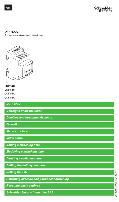
d d _E N 02/19IHP 1C/2CProduct information / menu descriptionCCT15440CCT15441CCT15442CCT15443d d _E N 02/19The IHP with weekly program controls lighting, air conditioning, flushing, etc.|The device must not control safety-relevant applications.G etting to know the timerDisplays and operating elementsA Time displayB Channel stateC Date displayD Programmed ON timesE Display of week daysF Display of active buttonsG OK buttonH Selection buttonsI MENU buttonOperationButton FunctionMENU button•Opens the menu•In menu mode: one step back:•In programming mode: cancel programming modeSelection buttons •Switch between menu items •Increase/decrease value OK button•In menu mode: select menu item •In programming mode: confirm settingMenu structurePROGRAM TIME/DATEMANUAL CONFIG ENDCHANNEL 1TIME CHANNEL 1LANGUAGENEW SET DATEPERM ON PIN CHECK SU-WI PERM OFF FACTORY SETTINGSMODIFY WEEK DAY OVERRI ONINFO DELETEFORM DATE HOLIDAYENDENDFORM TIMEENDd d _E N 02/19The basic settings, such as date, time, etc., must be carried out when starting for the first time or following a reset.The device starts in the settings menu with the item LANGUAGE .1Select the language.2Confirm the message FORM DATE .3Select the date format.4Set the year.5Set the month.6Set the day.7Confirm the message FORM TIME .8Select the time format.9Set the hours.0Set the minute.^Select summer time/winter time.A switching time always consists of one time at which the load is switched on and one time at which the load is switched off. Y ou can either set switching times for a specific day of the week or copy them for multiple week days. Copied week days are referred to as a block.T o set a switching time, perform the following steps once for ON and once for OFF :1Confirm message about free memory slots.2Select ON or OFF .3Set the hour.4Set the minute.5Set the day of the week.6If the switching time is only to be valid for one week day, select SAVE .The switching time is set.7If the switching time is to be copied as a block for multiple week days, select COPY .8Select further days of the week and confirm in each case.Week days contained in the block are indicated in the week days display.To remove a week day from the block, select the week day again using the selection buttons.9Once the desired week days have been set, select COPY .Initial setupSetting a switching timePROGRAMCHANNELC1CHANNELC2NEWNEWd d _E N 02/19Y ou can change the time for the switching times. In the case of switching times within a block, you can select whether the modification of the time is to apply to the whole block or only to a specific week day. This week day is then removed from the block.1Select the switching time.The display runs through all switching times in sequence. If no switching time is set for a week day, this is indicated in the display by --:--.If the selected switching time is part of a block, all days of the block are shown in the week day display. The selected week day flashes.2Set the hour.3Set the minute.4If the selected switching time is only set for one week day, only the option SAVE appears.5If the selected switching time is part of a block, select MODIFY BLOCK or MODIFY WEEK DAY .- MODIFY BLOCK changes the time for all switching times of the block.- MODIFY WEEK DAY changes the time for the selected switching time. The selected switching time is re-moved from the block.Y ou can delete switching times at any time. If a switching time is part of a block, you can delete the entire block or remove the switching time from the block. Y ou can also delete all switching times of a channel simultaneously.Deleting a switching time:1Select SINGLE .2Select the switching time.The display runs through all switching times in sequence. If no switching time is set for a week day, this is indicated in the display by --:--.If the selected switching time is part of a block, all days of the block are shown in the week day display. The selected week day flashes.3If the selected switching time is only valid for one week day, only the option DELETE WEEK DAY appears.4If the selected switching time is part of a block, select DELETE BLOCK or DELETE WEEK DAY .- DELETE BLOCK deletes all switching times of the block.- DELETE WEEK DAY removes the selected switching time from the block and deletes it.Deleting all switching times of a channel:1Select DELETE ALL .2Confirm with CONFIRM .Modifying a switching timePROGRAMCHANNELC1CHANNELC2MODIFYMODIFYDeleting a switching timePROGRAMCHANNELC1CHANNELC2DELETEDELETEd d _E N 02/19With the holiday function, you can switch a channel on or off completely for a longer period. The programmed switching times do not apply while the holiday function is active. Y ou can only set one holiday time per channel.1Select ON or OFF .2Confirm BEGIN HOLIDAY .3Set the year.4Set the month.5Set the day.6Set the hour.7Confirm END HOLIDAY .8Set the year.9Set the month.0Set the day.^Set the hour.A PIN protects against unauthorized use.If you have forgotten your PIN, contact the Customer Care centre in your country, stating the serial number of your device.1Select WITH PIN .NO PIN cancels the PIN protection function.2Confirm CURRENT PIN .3Set new PIN.|The PIN digits are set one after the other with +/- and confirmed with OK . A digit that has already been set can no longer be changed. When the last digit is confirmed with OK , the PIN is saved. If in any doubt, exit the PIN setting procedure with MENU .Setting the holiday functionMANUALCHANNELC1CHANNELC2HOLIDAYHOLIDAYSetting the PINCONFIGPINd d _E N 02/19Y ou can set override or permanent switching either via the MANUAL menu or using combinations of buttons on the device.Override switchingIf you wish to switch a channel briefly to the other switching state (e.g. from ON to OFF ), activate override. This state is only valid until the next switching time.If override is active, CHANNEL OVERRIDE appears briefly in the display.Permanent switchingIf you wish to switch a channel permanently, activate permanent switching. While permanent switching is activat-ed, switching times have no effect.If you want to select whether the channel is to be switched ON or OFF permanently, use the MANUAL menu.If you use the button combinations to activate permanent switching, the channel is switched to the other switching state (e.g. from ON to OFF ).If permanent switching is active, CHANNEL PERMANENT appears briefly in the display.Activating override and permanent switchingd d _E N 02/19Y ou can reset the basic settings, such as date, time, etc. and delete or keep all switching times.Y ou have two options: Y ou can either load the factory settings via the CONFIG menu or reset the device using combinations of buttons on the device.|Loading the factory settings will also delete all switching times. If you want to reset the basic settings and retain the switching times, use the reset function.Loading factory settings1Confirm the message LOAD FACTORY SETTINGS .2Set basic settings as described in chapter “Initial setup”.Resetting1Push all four buttons on the device simultaneously.2Select the language.3If you want to retain the switching times, select RETAIN PROGRAMS .4If you want to delete all switching times, select DELETE PROGRAMS .5Set basic settings as described in chapter “Initial setup”.If you have technical questions, please contact the Customer Care Centre in your /contactResetting basic settingsCONFIGFACTORY SET-TINGSSchneider Electric Industries SAS。
线切割单板控制器使用说明书1. 单板控制器接收程序:待命一上档一起始地址(即起始条数,下同)一B。
电脑送数控程序到单板机用“应答传送”送数。
注:所有操作前都需要按待命键,从而为后续命令的执行作准备!切记!2. 单板控制器程序校零:待命一上档一程序起始地址(即起始条数)一校零一校零,看X,Y 出现的数字是否小于10而确定程序是否正确。
〈5号和8号机单板控制器则为,待命一程序起始地址(即起始条数)一校零一校零。
〉3. 单板控制器座标清零:待命一上档一X或者丫一D,<5号和8号机单板控制器则为,待命一X或者丫一D。
(查看是否已经清零,待命一上档一X或者丫,看X,Y出现的数值是否为零,<5号和8号机单板控制器则为,待命一X或者丫〉4. 单板控制器提取程序出来加工:待命一程序起始地址(即起始条数)一执行一执行,即可开始加工。
5. 单板控制器中断,暂停或者退出加工:待命一(换档+D), <5号和8号机单板控制器则为,待命一上档一暂停〉先暂停加工,再按:待命一退出一退出一退出<5号和8号机单板控制器则为:待命一作废一作废一作废,3号和7号机单板控制器则为:打下加工开关即加工开关不在位再按退出键三次即可退出加工。
〉6. 单板控制器手动回退:待命一上档一回退(执行或者逆向键),如要回退很多,则按住不动,即可一直回退到这条程序的起始位置。
7. 单板控制器恢复加工:待命一(换档+D ),<5号和8号机单板控制器则为:待命一恢复〉即可恢复加工。
8. 单板控制器断丝回零:(单板控制器座标清零就是为了单板控制器断丝回零而作的工作,如果单板控制器座标清零没有执行则单板控制器断丝回零就没有任何意义。
)首先退出加工,然后按:待命一上档一L3然后空走至加工起始点,如果有锥度加工,则还要使锥度头回零,待命一上档一L4,然后锥度头空走回零〈5号和8号机单板控制器则为:待命—上档一XY回零,锥度则为待命一上档一UV回零〉9. 单板控制器逆切加工:待命一上档一程序起始地址(即起始条数)一(o 。
IntroductionPhilip Schmersal, managing director of the Schmersal Group andMichael Mandel, managing director of K.A. Schmersal GmbH & Co. KGWith its comprehensive range of about 25,000 products, Schmersal is one of the world‘sbiggest suppliers of safety technology.Schmersal is not only a manufacturer of safety components, but are also a system supplier.In developing the new PROTECT PSC1, we have taken a big step forward in the field of controltechnology. The multifunctional PROTECT PSC1 system consists of a reliable, programmablecompact safety controller and dependable extension modules and can be adapted perfectly tospecific applications in various branches of industry. With its combination of certain properties,the new safety controller from Schmersal is unparalleled, as the PROTECT PSC1 has uniquefeatures that clearly set this control system apart from other solutions on the market.The new generation of programmable modular safety controllers from Schmersal is embeddedin a comprehensive offering of safety services. Many of our customers want planning andadvice from the outset, e. g. in the design of complex automation systems. This also includesthe development of custom applications and their integration in higher-order control systems.A central element here is application consulting. Certified Functional Safety Engineers adviseour customers on suitable protection equipment, with the CE conformity assessment as well asthe risk analysis and also carry out the technical safety analysis on existing machines, and allthis worldwide.With another service, that of application engineering, Schmersal targets users of safetycontrollers in automation technology. For them, we develop customised software modulesthat enable safety functions to be tailored perfectly to the machine‘s or system‘s specificapplication.Above this, we regularly report to our customers and experts in the field on new developments inmachine safety. In short, we offer our customers an all-embracing package of integrated systemssolutions in the safety technology sector.2ContentIntroduction ________________________________________________________Page 2Content ___________________________________________________________Page 3PROTECT PSC1 ____________________________________________________Page 4User softwareProgramming software SafePLC2 ____________________________________Page 5Compact safety controller PSC1-C-100 __________________________________Page 6Compact safety controller PSC1-C-10 ___________________________________Page 7Safe I/O expansion modulesfor the compact safety controllers PSC1-C-10 and PSC1-C-1001) Central I/O expansion modules ____________________________________Page 82) D ecentral I/O expansion module – safe remote I/O communicationEthernet SDDC (Safety Device to Device Communication) _______________Page 9Safe Drive Monitoring (SDM) – Safe drive monitoring for up to 12 axes _________Page 10a) Safe drive monitoring of the compact safety controller PSC1-C-10 _________Page 11b) Safe drive monitoring of the compact safety controller PSC1-C-100 ________Page 11International ordering code for the safety controller PROTECT PSC1 ___________Page 12TopologiesS afe cross-communication – Ethernet SMMC ___________________________Page 13Safe remote I/O communication – Ethernet SDDC _______________________Page 13M odular compact safety controller PSC1-C-10 __________________________Page 14Modular compact safety controller PSC1-C-100 _________________________Page 14U niversal communication interface – universal fieldbus connection __________Page 15Universal communication interface – integrated SD-Bus-Gateway ___________Page 1534The safety control system PSC1 consists of freely programmable compact safety controllers with I/O extension modulesfor signal processing of emergency stop switches, guard door switches, light grids and additional mechanical and electronicsafety switchgear. Additionally there is the possibility via numerous functions to monitor axes.Using the universal communications interface a connection can be established to all the standard field bus systems.■ S afe logic control according to Annex IV of the Machinery Directive 2006/42/EC ■ C onnection for all standard safety relays up to PL e and SIL 3■ M odular expansion with up to 272 inputs / outputs ■ S ecure 2 A p-switching semiconductor outputs, can be switched to secure p-/n-switching semiconductor outputs ■ F reely programmable inputs / outputs, 2 A p-switching ■ S afe drive monitoring according to EN 61800-5-2 (SDM – Safe Drive Monitoring) for up to 12 axes ■ U niversal communication interface:- Supports all standard fieldbus systems- Setting and resetting of fieldbus protocols by software- Safe remote I/Os via Ethernet Safety Device to Device Communication (SDDC)- Safe cross-communication via Ethernet Safety Master to Master Communication (SMMC)■ I ntegrated Schmersal SD Bus connection to the standard field bus systems ■ S afety functionalities up to SIL 3 according to IEC 61508 / IEC 62061, PL e and Cat. 4 according to EN ISO 13849-1PROTECT PSC1Programmable modular safety controller5■ M odern, object oriented application development environment ■ P reconfigured elements for safe electronic and electromechanical switching devices ■ E asy reuse of application code by macros ■ P rogramming assistance by various search functions ■ S imple signal tracking by different colour representation and status messages ■ E asy to detect safety functions through practice oriented libraries for logic, Safe Drive Monitoring,SD-bus and encoder elements ■ C onfigurable user permissionsProgramming software SafePLC2User softwareProgramming software SafePLC26The PSC1-C-100 is a modular and freely programmable compact safety controller for safe signal processingof safety switchgear with the option of a universal communications interface.The base version of the PSC1-C-100 controller has the following properties:■ 14 safe inputs up to PL e respectively SIL 3■ 20 adjustable safe in-/outputs up to PL e respectively SIL 3, 2 A p-switching ■ 4 adjustable safe semiconductor outputs: 2 A p-switching or p-/n-switching ■ 2 safe relay outputs for 24 VDC or 230 VAC, 2 A ■ 2 signalling outputs, 250 mA ■ 2 pulse outputs (clock outputs) for contact sensors ■ 1 SDHC card slot for storing application programs (Memory-Card)■ M odular expandable up to 8 I/O modules (central / decentral)■ M odular expandable with up to 6 safe drive monitoring modules (max. 12 axes)■ U niversal communication interface (optional)Compact safety controller PSC1-C-100Basic version with memory card (SDHC)Universal communication interface incl. memory card (SDHC)7The PSC1-C-10 is a modular and freely programmable compact safety controller for safe signal processing of safety switchgear with the options of an integrated drive monitoring and/or a universal communications interface. The base version of the PSC1-C-10 controller has the following properties:■ 14 safe inputs up to PL e respectively SIL 3■ 4 adjustable safe semiconductor outputs: 2 A p-switching or p-/n-switching ■ 2 safe relay outputs for 24 VDC or 230 VAC, 2 A ■ 2 signalling outputs, 250 mA ■ 2 pulse outputs (clock outputs) for contact sensors ■ M odular expandable with up to 2 I/O expansion modules (central / decentral)■ O ptional expansions: Universal communication interface, memory card (SDHC), safe drive monitoring Compact safety controller PSC1-C-10Basic unit With integrated Safe Drive Monitoring (SDM) for 1 axis With integrated Safe Drive Monitoring (SDM) for 2 axes with Memory-Card (SDHC)with communication interface8The I/O expansion modules can be freely used for the compact safety controllers and differ in their application:1. Central applicationsa. in the same cabinet, directly aligned to the compact safety controllerb. communication via backplane bus2. Decentral applicationsa. remote control cabinetb. communication to the compact safety controller via Ethernet SDDCSafe I/O expansion modulesfor the compact safety controllers PSC1-C-10 and PSC1-C-100Technical specification:PSC1-E-31-12DI-10DIOPSC1-E-131-12DI-10DIO■ 12 safe inputs up to PL e respectively SIL 3■ 10 adjustable safe in-/outputs up to PL erespectively SIL 3, 2 A p-switching ■ 2 signalling outputs, 250 mA ■ 2 pulse outputs (clock outputs)for contact sensors 1) Central I/O expansion modulesTechnical specification: PSC1-E-33-12DI-6DIO-4RO PSC1-E-133-12DI-6DIO-4RO ■ 12 safe inputs up to PL e respectively SIL 3■ 6 adjustable safe in-/outputs up to PL e respectively SIL 3, 2 A p-switching ■ 4 safe relay outputs for 24 VDC or 230 VAC, 2 A ■ 2 signalling outputs, 250 mA ■ 2 pulse outputs (clock outputs)for contact sensors9In applications with separated collecting points for safety switchingdevices, a decentral I/O expansion module is available. The safety logicfor the entire system is stored only in the compact safety controller. Thesafe remote I/O modules transmit and receive their status via the safelocal communication protocol Ethernet SDDC.2) D ecentral I/O expansion module – safe remote I/O communicationEthernet SDDC (Safety Device to Device Communication)Technical specification:PSC1-E-37-14DI-4DO-2RO-RIO■ 14 safe inputs up to PL e respectively SIL 3■ 4 adjustable safe semiconductor outputs: 2 A p-switching or p-/n-switching ■ 2 safe relay outputs for 24 VDC or 230 VAC, 2 A ■ 2 signalling outputs, 250 mA ■ 2 pulse outputs (clock outputs) for contact sensorsA mixture of centralised and decentralised applications are possible for both compact safety controller systems PSC1-C-10 and PSC1-C-100.10For safe drive monitoring many safety features are supported:■ S afe shut-down: Safe Torque OFF (STO), Safe Break Control (SBC)■ S afe stopping: Safe Stop 1 (SS1), Safe Stop 2 (SS2), Safe Operating Stop (SOS)■ S afe movement: Safely-Limited Speed (SLS), Safe Speed Range (SSR), Safe Direction (SDI), Safely-Limited Acceleration (SLA), Safe Acceleration Range (SAR)■ S afe monitoring: Safe Speed Monitor (SSM), Safe Cam (SCA)■ S afe Positioning: Safely-Limited Position (SLP), Safely-Limited Increment (SLI), Safely Emergency Limit (SEL)The drive monitoring is carried out depending on the application requirements, with one or two encoder systems. The following encoder signals are supported:■ 1 Encoder system: TTL, SIN/COS, SSI (Gray code / binary code)■ 2 Encoder systems: TTL, SIN/COS, SSI (Gray code / binary code), Resolver, HTLSafe Drive Monitoring (SDM)Safe drive monitoring for up to 12 axes11The safe drive monitoring with the compact safety controller PSC1-C-10 is realised by an integrated solution. Depending on the order option, the compact safety controller can safely monitor 1 or 2 axes with one encoder system.a) S afe drive monitoring of the compact safety controller PSC1-C-10A safe drive monitoring is realised with the compact safety controller PSC1-C-100 via extension modules. In this case, each axis can be safely monitored by one or two encoders. The drive monitoring modules are available for one or two encoders.b) Safe drive monitoring of the compact safety controller PSC1-C-100Monitoring up to 12 axes with up to 6 expansion modulesOrder option: integrated safe drive monitoring up to 2 axes2 axes1 axisSafe drive monitoring with one encoder each For 1 axis:■ P SC1-E-21-SDM1Safe drive monitoring with two encoders each For 1 axis:■ P SC1-E-22-SDM1-2For 2 axes:■ P SC1-E-23-SDM2For 2 axes:■ PSC1-E-24-SDM2-212International ordering codeController system PROTECT PSC1PROTECT PSC1 - Programmable modular safety controller1)under preparation13Safe cross-communication –Ethernet SMMC (Safety Master to Master Communication)Safe remote I/O communication –Ethernet SDDC (Safety Device to Device Communication)The safe cross-communication is used as a composite of safety controllers to safely exchange data via the local Ethernet SMMC communication. In a complete system (consisting of individual system components) with concatenated EMERGENCY STOP signals or concatenated signals from solenoid interlocks, this requirement can be solved by using the safe cross-communication. The simultaneous operation of safe cross- communication and safe remote I/O communication and a field-bus communication for a superordinate control is possible.■ S afe cross-communication withup to 4 compact safety controllers PSC1■ F ree mixing of compact safety controllers PSC1-C-10 and PSC1-C-100For the decentral application structure the remote I/O expansion modulePSC1-E-37-14DI-4DO-2RO-RIO is available.The local communication is realised via the Ethernet SDDC protocol.This ensures that the simultaneous operating of the safe cross-communication and the safe remote I/O communication can take placeover the universal communication interface.14Modular compact safety controller PSC1-C-102 expansion modules / up to 64 I/OsModular compact safety controller PSC1-C-1008 expansion modules / up to 272 I/OsThe compact safety controller PSC1-C-10 can be expanded with up to 2 I/O expansion modules.A mixture of centralised and decentralised structures can be used.The compact safety controller PSC1-C-100 can be expanded with up to 8 I/O expansion modules.A mixture of centralised and decentralised structures can be used.Central structure:I/O expansion modules■ P SC1-E-131-12DI-10DIO■ P SC1-E-133-12DI-6DIO-4RODecentral structure:Expandable with theremote I/O module■ P SC1-E-37-14DI-4DO-2RO-RIODecentral structure:Expandable with theremote I/O module■ PSC1-E-37-14DI-4DO-2RO-RIOCentral structure:I/O expansion modules■ P SC1-E-31-12DI-10DIO■ PSC1-E-33-12DI-6DIO-4RO•• •15Universal communication interface – Universal field-bus connectionUniversal communication interface – Integrated SD Bus gatewayUsing the universal communication interface the required field-bus protocol can be manually selected via software.Parallel to the active field-bus protocol the local communication within the PSC1 control system can be realised via the Ethernet SDDC and SMMC.Up to 31 Schmersal SD bus sensors can be connected and evaluated with their extended diagnostic data directly onto the compact safety controller PSC1.In doing so, the universal communication interface takes on the task of a gateway to the respective field-bus protocols, set via software (communication to machinecontroller).Under preparationAvailablex.000 / L+W / 01.2018 / Teile-Nr. 103009155 / EN / Ausgabe 05*103009155#。
C1控制器使用说明书
一、C1系统特点
1、32级—65536级灰度控制,软件Gamma校正处理。
2、支持各种点、线、面光源,支持各种规则,异形处理。
3、控制器单口输出,最大可带2048像素点。
4、脱机控制,播放内容存放在SD卡中。
5、C1最多存放16个文件,将多个文件依次拷贝到SD卡即可。
6、存放在SD卡里的效果应该依次命名为:00_1.led, 01_1.led, 02_1.led.
7、兼容单双线IC,接单线IC的灯具时,无需接CLK时钟线。
注:1. C1端口带载512灯时,播放速度可达30帧/秒,端口带载超过512灯时,帧频随
灯数的增加而自动降低。
二、支持芯片:
支持芯片Ledctrl软件对应型号单台带载灯数
备注
TM1803,TM1804,TM1809,TM1812 C1-TM 2048像素有高速和低速之分TM1829 C1-TM1829 2048像素有高速和低速之分UCS1903,UCS1903B ,UCS1909,UCS1912 C1-UCS256 2048像素有高速和低速之分UCS2903,UCS2909,UCS2912, C1-UCS256 2048像素有高速和低速之分UCS6909,UCS6912,UCS7009,UCS5903 C1-UCS32 2048像素
WS2811 C1-WS2811 2048像素有高速和低速之分INK1003 C1-TM 2048像素有高速和低速之分TLS3100 C1-TM 2048像素有高速和低速之分SM16711 C1-SM16711 2048像素有高速和低速之分SM16716 C1-SM16716 2048像素
SM16726 C1-SM16726 2048像素
LPD6803,D705,1101 C1-6803 2048像素
LPD8806,LPD8809 C1-8806 2048像素
P9813 C1-P9813 2048像素
WS2801,WS2803 C1-WS2801 2048像素
GW6203 C1-TM 2048像素
三、外观图片:
图一
图二
四、丝印含义:
按键含义:
按键含义
保存SET 保存设置(若按SET键,则当前设置文件和播放速度被保存,下次开机后仍按此播放)。
模式MODE切换文件
速度SPEED+速度加快同时按下SPEED+和SPEED-,则进入文件循环播放模式
速度SPEED-速度减慢
TTL信号(245信号):
CLK 时钟线电源灯POWER 电源指示灯
DAT 数据线故障灯ERROR 错误指示灯
GND 地线SD SD卡插槽
注:针对TTL信号的输出,控制器一定要和灯具进行供地(也就是将控制器的地线输出和灯具的地线连接到一起)。
五、接线方式
注:1、C1为单口输出,最多可带2048个像素点;
2、当控制单线IC时只需将控制器的DAT和GND与灯具的DAT和GND相对应连接起来即可。
当控制双线IC时需把控制器的DAT.CLK 和GND与灯具的DAT,CLK和GND相对应连接起来即可。
3、在效果编辑软件中新建项目时候,选择控制型号为:C1-IC型号
六、文件存储:
文件命名规则:
单台控制器效果命名规则
“00_1.led” ---------第1个效果
“01_1.led” ---------第2个效果
“02_1.led” ---------第3个效果
“03_1.led” ---------第4个效果
七、具体参数:
储存卡:
类型:SD卡
容量:128MB—2GB
格式:FAT格式
储存文件:*.led
物理参数:
工作温度:-30℃—85℃
工作电源:直流5V输入
功耗:1W
数据传输端口:3pin 接线端子
重量:0.25Kg带外包装(3pin接线端子*1;SD卡*1;电源适配器*1;纸盒*1)
尺寸:
注意事项:
将文件拷贝到SD卡之前,必须先对SD卡格式化,注意是每次拷贝之前都要格式化。
SD卡必须要格式化成“FAT“格式。
备注:控制器上的SD卡不可以热插拔,即每次插拔SD卡时,必须先断开控制器的电源。
八、常见问题处理:
问题1:上电后,发现C1的错误指示灯ERROR一直在闪烁,并且没有效果输出
答:错误指示灯ERROR一直在闪烁证明控制器没有正确读卡,可能存在的问题有:
①SD卡里面为空,没有效果文件。
②SD卡里面效果文件*.led文件和控制器型号不匹配,请在最新版本Ledctrl里面正确选择控制器的型号C1-芯片型号,并重新制作效果文件*.led.
③SD卡在拷贝效果文件之前没有格式化成FAT各式。
④更换SD卡后再进行测试,排除SD卡坏的可能性。
⑤效果文件名错误,更改为00.led。
问题2:控制器上电后,指示灯正常,但灯具无效果变化
答:这种情况的原因有以下几点:
①请检查灯具的信号线和控制器有没有正确连接。
②灯具和控制器一定要共地,即灯具的地线要和控制器的地线接到一起。
③请检查制作SD卡中效果文件*.led时所选的型号是否和当前灯具所用芯片一致。
问题3:控制器与灯具接上后,灯具频闪,且有效果变化,同时控制器指示灯显示正常。
答:①控制器与灯具之间的地线没有连接。
②SD卡里面所做的效果有误,做效果时选择的灯具芯片和实际灯具的芯片不符。
③灯具的供电电压不足。
问题4:SD卡无法格式化。
答:①首先确认SD卡的侧面的保护开关是否已经开锁。
开锁的方向为SD卡金针这端。
②保护锁已经按要求设计,但依然无法格式化,如果出现这种情况多数为SD卡读卡器坏了,请更
换SD卡读书器。
③如以上操作都无法解决格式化的问题,请更换SD卡,重新测试。