OMRON限位开关hl-5050
- 格式:doc
- 大小:2.15 MB
- 文档页数:5
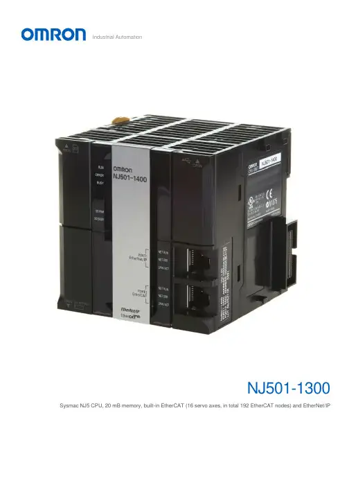
Industrial AutomationSysmac NJ5 CPU, 20 mB memory, built-in EtherCAT (16 servo axes, in total 192 EtherCAT nodes) and EtherNet/IPController functionality Motion control, OPC-UA, Sequence control Max. number of synchronous axes16Max. number of axes (incl. virtual)16Max. number of robots0Primary task cycle time0.5 msProgram memory20 MBVariables memory 6 MBCommunication port(s)EtherCAT Master, EtherNet/IP, USBCommunication option(s)CAN, CompoNet Master, DeviceNet Master, DeviceNet Slave, EtherCAT Slave, MODBUS Master, MODBUS Slave, PROFIBUS DP Master, PROFIBUS DP Slave, PROFINET Master, Serial RS-232C, Serial RS-422, Serial RS-485Max. number of remote I/O nodes192I/O system CJ I/O Bus Max. number of expansion units40 Height90 mm Width90 mm Depth90 mm Weight550 gGX-JC033-port EtherCAT Junction module, 24 VDC power supplyGX-JC066-port EtherCAT Junction module, 24 VDC power supplyGX-JC06-H6-port EtherCAT Junction module, 24 VDC power supply, with node switchesHMC-SD492 4 GB SD memory cardNJ-PA3001Sysmac NJ power supply unit, 100-240 VAC, 30 W, "RUN" output relayNJ-PD3001Sysmac NJ power supply unit, 24 VDC, 30 W, "RUN" output relayW4S1-05D 5-port enhanced Ethernet switchCJ1W-BAT01Battery for CJ1M PLCsCJ1W-TER01End plate for CJ1 CPU rack or expansion rack. Only required as spare part.FDK CR14250SE Battery Safety DatasheetEN PDF 147 KBNJ-Series DatasheetEN PDF 3.05 MBNJ-Series CPU Unit Hardware Users ManualENPDF 6.95 MBNJ-series -[DeviceNet]-3G3MX2-series Inverter Connection GuideENZIP 2.98 MBNJ-series -[DeviceNet]-3G3RX-V1-series InverterConnection GuideENZIP 3.75 MBNJ-series -[DeviceNet]-ABB IRC5 Robot Controller Connection GuideEN ZIP 5.81 MBNJ-series -[DeviceNet]-NE1A-series Safety Network Controller Connection GuideENPDF 3.47 MBNJ-series -[EtherCAT]-3G3MX2-series Inverter Connection GuideENPDF 1.72 MBNJ-series -[EtherCAT]-3G3MX2-series Type V1Connection GuideENPDF 2.18 MBNJ-series -[EtherCAT]-3G3RX-V1-series InverterConnection GuideENPDF 2.28 MBNJ-series -[EtherCAT]-Balluff BNI ECT-508Connection GuideENPDF 1.85 MBNJ-series -[EtherCAT]-Balluff RFID (BIS V Series)Connection GuideENPDF 1.76 MBNJ-series -[EtherCAT]-CKD MW4G-seriesNW4Gx-T7ECxxx (W4G-OPP8-xEC-xx)Connection GuideEN PDF 1.2 MBNJ-series -[EtherCAT]-Copley Accelnet Connection GuideENZIP 5.75 MBNJ-series -[EtherCAT]-Copley Xenus Plus XEL Connection GuideENZIP 3.81 MBNJ-series -[EtherCAT]-DELTA ELECTRONICS ASDA-A2-series Connection GuideEN ZIP 3.72 MBNJ-series -[EtherCAT]-DELTA R1-EC-series Slave Remote Module Connection GuideENPDF 2.22 MBNJ-series -[EtherCAT]-DENSO WAVE RC8Robot Controller Connection GuideENPDF 3.54 MBNJ-series -[EtherCAT]-E3NW-ECT DigitalSensor Communication UnitConnection GuideEN PDF 2.01 MBNJ-series -[EtherCAT]-E3X-ECTConnection GuideENPDF 2.41 MBNJ-series -[EtherCAT]-Elmo Gold Solo Whistle Digital Servo Drive Connection GuideEN ZIP 3.49 MBNJ-series -[EtherCAT]-FANUC R-30iB Robot Controller Connection GuideENPDF 3.82 MBNJ-series -[EtherCAT]-FESTO CPX-FB38 Valve Terminals MPA Connection GuideENPDF 2.47 MBNJ-series -[EtherCAT]-FESTO CTEU-EC Valve Terminals VTUB-12Connection GuideENPDF 2.52 MBNJ-series -[EtherCAT]-FESTO Valve Terminals MPA CPX-FB37Connection GuideENPDF 2.01 MBNJ-series -[EtherCAT]-FH-series Vision System Connection GuideENPDF 2.38 MBNJ-series -[EtherCAT]-FQ-MS12x(-M)-ECT Vision Sensor Connection GuideENPDF 2.63 MBNJ-series -[EtherCAT]-GRT1-ECT SmartSlice Connection GuideENPDF 2.9 MBNJ-series -[EtherCAT]-GX-ILM08C -[IO-Link]-Balluff Cylinder Sensor (BMF 203K)Connection GuideEN PDF 2.24 MBNJ-series -[EtherCAT]-GX-ILMxxx -[IO-Link]-E2E-series Proximity SensorConnection GuideEN PDF 2.31 MBNJ-series -[EtherCAT]-GX-ILMxxx -[IO-Link]-E3Z-series Photoelectric SensorConnection GuideEN PDF 2.24 MBNJ-series -[EtherCAT]-GX-series Analog I/O TerminalConnection GuideENPDF 1.74 MBNJ-series -[EtherCAT]-GX-series Digital I/O TerminalConnection GuideENPDF 1.74 MBNJ-series -[EtherCAT]-GX-series Encoder Input TerminalConnection GuideENPDF 1.75 MBNJ-series -[EtherCAT]-HENGSTLER ACURO(R)AC58-series Absolute EncoderConnection GuideENPDF 1.47 MBNJ-series -[EtherCAT]-HIWIN D1-N-series Connection GuideENZIP 3.85 MBNJ-series -[EtherCAT]-HMS Anybus Communicator Connection GuideENPDF 1.93 MBNJ-series -[EtherCAT]-HMS Anybus X-gateway Connection GuideENPDF 3.16 MBNJ-series -[EtherCAT]-HORIBA STEC SEC-Z500X-series Mass Flow ControllerConnection GuideEN PDF 1.5 MBNJ-series -[EtherCAT]-Hivertec HES-C400/NJ Connection GuideENPDF 2.14 MBNJ-series -[EtherCAT]-Hivertec HES-M4xx/NJ Connection GuideENPDF 1.89 MBNJ-series -[EtherCAT]-IAI ACON/ACON-CA/PCON/PCON-CA/DCON-CA ControllerConnection GuideEN PDF 1.38 MBNJ-series -[EtherCAT]-IAI Corporation MSCON Controller Connection GuideENPDF 2.88 MBNJ-series -[EtherCAT]-IAI Corporation MSEP Controller Connection GuideENPDF 1.48 MBNJ-series -[EtherCAT]-IAI SCON-CA/SCON-CAL Controller Connection GuideENPDF 2.12 MBNJ-series -[EtherCAT]-IAI X-SEL Controller XSEL-R/S/RX/SX/RXD/SXDConnection GuideEN PDF 2.67 MB NJ-series -[EtherCAT]-KYOWA SENERGYController (MotionLinxSeries)Connection GuideEN PDF 1.72 MBNJ-series -[EtherCAT]-M-System R30-seriesRemote I/OConnection GuideENPDF 1.74 MBNJ-series -[EtherCAT]-M-System R8-seriesRemote I/OConnection GuideENPDF 2.19 MBNJ-series -[EtherCAT]-MTS KG R-series LinearPosition SensorsConnection GuideENPDF 2.46 MBNJ-series -[EtherCAT]-NX-ECC + NX-ILM400 -[IO-Link]- E2E-seriesProximity SensorConnection GuideEN PDF 2.44 MBNJ-series -[EtherCAT]-NX-ECC + NX-ILM400 -[IO-Link]- E3Z-seriesPhotoelectric SensorConnection GuideEN PDF 2.5 MBNJ-series -[EtherCAT]-NX-ECC + NX-ILM400 -[IO-Link]- FESTO SFAW-series W Flow SensorConnection GuideEN PDF 2.62 MBNJ-series -[EtherCAT]-NX-ECC + NX-ILM400 -[IO-Link]- FESTO SPAE-Pressure SensorConnection GuideEN PDF 2.42 MBNJ-series -[EtherCAT]-NX-ECC + NX-ILM400 -[IO-Link]- FESTO VPPM-seriesConnection GuideENPDF 2.35 MBNJ-series -[EtherCAT]-NX-ECC + NX-ILM400 -[IO-Link]- Piab ABVac.EjectorpiCOMPACT23Connection GuideEN PDF 2.68 MBNJ-series -[EtherCAT]-NX-ECC + NX-ILM400 -[IO-Link]- Turck I/O Hub(TBIL)Connection GuideEN PDF 2.76 MBNJ-series -[EtherCAT]-NX-PG0122 -[Pulse]-ORIENTAL MOTOR RK IIStepping MotorConnection GuideEN ZIP 6.11 MBNJ-series -[EtherCAT]-NX-PG0122 -[Pulse]-ORIENTAL MOTORStepping Motor αSTEPConnection GuideEN ZIP 8.5 MBNJ-series -[EtherCAT]-ORIENTAL MOTORNETC01-ECT NetworkConverterConnection GuideEN PDF 2.96 MBNJ-series -[EtherCAT]-ORIENTAL MOTORaSTEP DC Multi-AxisDrive (AZDxA-KED)Connection GuideEN PDF 3.99 MBNJ-series -[EtherCAT]-PHOENIX CONTACTAXL E ECx Axioline EConnection GuideEN PDF 2.71 MBNJ-series -[EtherCAT]-PHOENIX CONTACTAxioline F-series I/OsystemConnection GuideEN PDF 2.07 MBNJ-series -[EtherCAT]-SANYO DENKISANMOTION R TYPE SConnection GuideEN ZIP 4.28 MBNJ-series -[EtherCAT]-SMC EX180-SEC5-X23xSI UnitConnection GuideEN PDF 2.04 MBNJ-series -[EtherCAT]-SMC EX260-SECx SIUnitConnection GuideEN PDF 2.14 MBNJ-series -[EtherCAT]-SMC EX600-SECx SIUnitConnection GuideENPDF 2.62 MBNJ-series -[EtherCAT]-SMC IN587 SI unitConnection GuideENPDF 2.27 MBNJ-series -[EtherCAT]-SMC JXCE1 Direct inputtype Step MotorControllerConnection GuideEN PDF 1.59 MBNJ-series -[EtherCAT]-THK Network Unit TNU-EC Electrical Actuator Controller Connection GuideEN PDF 2.28 MBNJ-series -[EtherCAT]-Turck BL20-E-GW-EC GatewayConnection GuideENPDF 2.13 MBNJ-series -[EtherCAT]-VAT612/615/642/650/652/951/952/62/67Control ValveConnection GuideEN PDF 2.91 MBNJ-series -[EtherCAT]-WAGO I/O-SYSTEM 750-series Fieldbus Coupler Connection GuideENPDF 2.55 MBNJ-series -[EtherCAT]-YASKAWA Σ-V-series SGDV-xxxxE1Connection GuideEN ZIP 6.95 MBNJ-series -[EtherCAT]-ZW-7000-seriesDisplacement Sensor Connection GuideENPDF 2.11 MBNJ-series -[EtherCAT]-ZW-CE1 Displacement SensorConnection GuideENPDF 1.98 MBNJ-series -[EtherNet/IP]-ABB IRC5 Robot Controller Connection GuideEN ZIP 6.44 MBNJ-series -[EtherNet/IP]-CJ2-series Controller Connection GuideENZIP 6.41 MBNJ-series -[EtherNet/IP]-CK3M-CPU1x1Connection GuideENPDF 3.93 MBNJ-series -[EtherNet/IP]-DENSO WAVE RC7M Robot Controller Connection GuideEN ZIP 3.83 MBNJ-series -[EtherNet/IP]-DENSO WAVE RC8Robot Controller Connection GuideEN ZIP 5.39 MBNJ-series -[EtherNet/IP]-FH-series Vision System Connection GuideENZIP 1.96 MBNJ-series -[EtherNet/IP]-FQ2-series Smart CameraConnection GuideEN ZIP 3.55 MBNJ-series -[EtherNet/IP]-FZ4-series Vision SensorConnection GuideENZIP 1.74 MBNJ-series -[EtherNet/IP]-FZ5-series Vision SystemConnection GuideEN ZIP 1.93 MBNJ-series -[EtherNet/IP]-IAI CorporationACON/PCON/DCON/SCON Controller Connection GuideEN ZIP 2.73 MBNJ-series -[EtherNet/IP]-IAI Corporation XSEL-Rx/Sx ControllerConnection GuideEN ZIP 4.93 MBNJ-series -[EtherNet/IP]-Nidec Sankyo SC5000-seriesConnection GuideENZIP 7.36 MBNJ-series -[EtherNet/IP]-Omron Adept Robot ePLCConnection GuideENZIP 2.47 MBNJ-series -[EtherNet/IP]-Omron Adept Robot ePLCIOConnection GuideEN ZIP 2.6 MBNJ-series -[EtherNet/IP]-PHOENIX CONTACT AXL E-series I/O DeviceConnection GuideEN ZIP 2.22 MBNJ-series -[EtherNet/IP]-SMC EX600-SENx SI UnitConnection GuideEN ZIP 2.59 MBNJ-series -[EtherNet/IP]-SMC JXC91 Step Motor ControllerConnection GuideEN PDF 2.1 MBNJ-series -[EtherNet/IP]-Seiko Epson RC180 Robot Controller Connection GuideENZIP 2.6 MB NJ-series -[EtherNet/IP]-Turck BL20-E-GW-ENMultiprotocol GatewayConnection GuideEN ZIP 2.21 MBNJ-series -[EtherNet/IP]-Turck TBEN-seriesCompact Block I/O-moduleConnection GuideENZIP 1.57 MBNJ-series -[EtherNet/IP]-V680S-series RFIDConnection GuideEN ZIP 2.28 MBNJ-series -[EtherNet/IP]-WAGO I/O-SYSTEM 750-series Ethernet FieldbusCouplerConnection GuideEN ZIP 2.44 MBNJ-series -[EtherNet/IP]-Yamaha Motor RCX-series Robot ControllerConnection GuideEN ZIP 3.98 MBNJ-series -[EtherNet/IP]-Yamaha Motor TS-seriesSingle-axis RobotControllerConnection GuideEN ZIP 5.84 MBNJ-series -[EtherNet/IP]-Yamaha RCX340 RobotControllerConnection GuideEN ZIP 4.75 MBNJ-series -[EtherNet/IP]-ZW-7000-seriesDisplacement SensorConnection GuideEN ZIP 2.52 MBNJ-series -[EtherNet/IP]-ZW-CE1 DisplacementSensorConnection GuideEN ZIP 4.26 MBNJ-series -[EthernetTCP/IP]- FQ-CR-seriesConnection GuideEN ZIP 3.11 MBNJ-series -[EthernetTCP/IP]- Janome SewingMachine JR3000-seriesRobotConnection GuideEN ZIP 1.85 MBNJ-series -[EthernetTCP/IP]- MARS TOHKEN2D Image Reader (MVF-300/500 Series)Connection GuideEN PDF 2.05 MBNJ-series -[EthernetTCP/IP]- SCHOTTMORITEX MLEF-seriesDigital ControllerConnection GuideEN ZIP 2.75 MBNJ-series -[EthernetTCP/IP]- V750-seriesRFID SystemConnection GuideEN ZIP 4.7 MBNJ-series -[EthernetTCP/IP]- ZW-seriesDisplacement SensorConnection GuideEN ZIP 4.35 MBNJ-series -[RS-232C]-G9SP Safety ControllerConnection GuideEN ZIP 4.5 MBNJ-series -[RS-232C]-V400-R2-series UltraSmall Multi-code ReaderConnection GuideEN ZIP 4.64 MBNJ-series -[RS-232C]-V500-R2-series FixedLaser-Type BarcodeReaderConnection GuideEN ZIP 4.71 MBNJ-series -[RS-232C]-V750-series RFIDSystemConnection GuideEN ZIP 5.11 MBNJ-series -[RS-232C]-ZW-series DisplacementSensorConnection GuideEN ZIP 4.68 MBNJ-series -[RS-485CompoWay/F]-E5CC/E5EC/E5ACDigital ControllerConnection GuideEN ZIP 4.71 MBNJ-series -[RS-485CompoWay/F]-KM1/KE1-seriesConnection GuideEN ZIP 5.4 MBNJ-series -[RS-485Modbus]- ORIENTALMOTOR BLE-seriesBrushless MotorConnection GuideEN ZIP 2.67 MBNJ-series -[RS-485 Modbus]- ORIENTAL MOTOR RK II-series Stepping MotorConnection GuideEN ZIP 5.5 MB NJ-series -[RS-485Modbus]- ORIENTALMOTOR αSTEP AR-seriesConnection GuideEN ZIP 2.83 MBNJ-series -[RS-485Modbus]- ORIENTALMOTOR αSTEP AZ-seriesConnection GuideEN ZIP 3.01 MBNJ/NX SeriesBrochureEN PDF 6.96 MBNJ/NX-Series CPU UnitBuilt-in EtherCAT PortUsers ManualENPDF 16.3 MBNJ/NX-Series CPU UnitBuilt-in EtherNet/IP PortUsers ManualEN PDF 13.4 MBNJ/NX-Series CPU UnitMotion ControlUsers ManualEN PDF 20 MBNJ/NX-Series CPU UnitSoftwareUsers ManualENPDF 22.3 MBNJ/NX-SeriesInstructionsReference ManualENPDF 16 MBNJ/NX-Series MotionControl InstructionsReference ManualENPDF 4.93 MBNJ/NX-Series OPC UACPU UnitsUsers ManualENPDF 3.73 MBNJ/NX-SeriesTroubleshooting ManualUsers ManualENPDF 16.4 MBNJ/NX-Series for MotionControlGetting Started GuideENPDF 18.1 MBNJ/NX-series -[EtherCAT]- CKDABSODEX driver(AX9000TS/TH-U5)Connection GuideEN PDF 1.73 MBNJ/NX-series -[EtherCAT]- HitachiADV-Series AC ServoDrivesConnection GuideEN ZIP 4.29 MBNJ/NX-series -[EtherCAT]- Inficongauge (BPG402-SE)Connection GuideEN PDF 1.22 MBNJ/NX-series -[EtherCAT]- KashiyamaDry Vacuum Pump (E-CAT01 1ch)Connection GuideENPDF 1.59 MBNJ/NX-series -[EtherCAT]- NX-ECC +NX-ILM400 -[IO-Link]-CKD Sensor (PPXseries)Connection GuideEN PDF 2.43 MBNJ/NX-series -[EtherCAT]- NX-ECC +NX-ILM400 -[IO-Link]-CKD Sensor (WFCseries)Connection GuideEN PDF 2.75 MBNJ/NX-series -[EtherCAT]- NX-ECC +NX-ILM400 -[IO-Link]-CKD WFK2 Flow sensorConnection GuideEN PDF 2.09 MBNJ/NX-series -[EtherCAT]- NX-ECC +NX-ILM400 -[IO-Link]-MTS Sensors (E-Series)Connection GuideEN PDF 2.4 MBNJ/NX-series -[EtherCAT]- NX-ECC +NX-ILM400 -[IO-Link]-PATLITE Beacon (NE-IL)Connection GuideEN PDF 2.02 MBNJ/NX-series -[EtherCAT]- NX-ECC +NX-ILM400 -[IO-Link]-PATLITE Tower (LR6-IL)Connection GuideEN PDF 2.08 MBNJ/NX-series -[EtherCAT]- NX-ECC +NX-ILM400 -[IO-Link]-SMC (ISA3-xxx)Connection GuideEN PDF 2.61 MBNJ/NX-series -[EtherCAT]- NX-ECC +NX-ILM400 -[IO-Link]-SMC (xSE20Bx-L(-M/-P)-x)Connection GuideEN PDF 2.13 MBNJ/NX-series -[EtherCAT]- NX-ECC +NX-ILM400 -[IO-Link]-SMC ITVx000/-IO*Connection GuideEN PDF 1.89 MBNJ/NX-series -[EtherCAT]- NX-ECC +NX-ILM400 -[IO-Link]-SMC Servo 24VDC(JXCL1)Connection GuideEN PDF 2.23 MBNJ/NX-series -[EtherCAT]- NX-ECC +NX-ILM400 -[IO-Link]-Schmalz Ejector (SCPSi)Connection GuideEN PDF 2.4 MBNJ/NX-series -[EtherCAT]- NX-ECC +NX-ILM400 -[IO-Link]-ifm (O5D10x/O5D15x)Connection GuideEN PDF 2.42 MBNJ/NX-series -[EtherCAT]- NX-ECC +NX-ILM400 -[IO-Link]-ifm (PN7x94)Connection GuideEN PDF 2.72 MBNJ/NX-series -[EtherCAT]- NX-ECC +NX-ILM400 -[IO-Link]-ifm (TN24xx)Connection GuideEN PDF 2.74 MBNJ/NX-series -[EtherCAT]- NX-ECC +NX-ILM400 -[IO-Link]-ifm TR7439 Pt100/1000Connection GuideEN PDF 2.43 MBNJ/NX-series -[EtherCAT]- NidecSankyo S-FLAG II SeriesAC Servo (DB6xx41)Connection GuideEN PDF 2.65 MBNJ/NX-series -[EtherCAT]- ORIENTAL MOTOR Stepper Motor(AZ-series)Connection GuideEN PDF 2.89 MBNJ/NX-series -[EtherCAT]- SANYO DENKI AC ServoSANMOTION R 3E MODEL TYPE SConnection GuideEN PDF 3.08 MBNJ/NX-series -[EtherCAT]- SANYODENKI AC ServoSANMOTION RADVANCED MODEL TYPE FConnection GuideEN PDF 3.61 MBNJ/NX-series -[EtherCAT]- SHIMADZU Power Unit for TurboMolecular Pump (TMP)Connection GuideEN PDF 1.29 MBNJ/NX-series -[EtherCAT]- SICK Absolute Encoder (AFS60/AFM60)Connection GuideEN PDF 1.52 MBNJ/NX-series -[EtherCAT]- Schmalz Compact Terminal(SCTSi-ECT)Connection GuideEN PDF 1.33 MB NJ/NX-series -[EtherCAT]- WeidmüllerRemote I/O System (u-remote IP20)Connection GuideEN PDF 1.8 MBNJ/NX-series -[EtherCAT]- YASKAWA Σ-7-seriesConnection GuideEN ZIP 3.77 MBNJ/NX-series -[EtherNet/IP]- Balluff BNI EIP-50x-105-Z015Connection GuideEN PDF 3.35 MBNJ/NX-series -[EtherNet/IP]- CKD ABSODEX Driver (AX9000TS/TH-U6)Connection GuideEN PDF 1.71 MBNJ/NX-series -[EtherNet/IP]- HMSAnybus Communicator Connection GuideEN PDF 1.51 MBNJ/NX-series -[EtherNet/IP]- Hilscher netTAP NT100 Gateway (NT 100-RE-DN)Connection GuideEN PDF 3.5 MBNJ/NX-series -[EtherNet/IP]- IAI RCON system & MCON /MSCON / MSEP ControllerConnection GuideEN PDF 1.9 MBNJ/NX-series -[EtherNet/IP]- KOGANEI Manifold Solenoid Valve (F Series)Connection GuideEN PDF 2.43 MBNJ/NX-series -[EtherNet/IP]- Nordson ProBlue Adhesive MeltersConnection GuideEN PDF 2.61 MBNJ/NX-series -[EtherNet/IP]- ORIENTAL MOTOR αSTEP Compatible Driver (AZD-xEP)Connection GuideEN PDF 1.82 MB NJ/NX-series -[EtherNet/IP]- SMCSolenoid Valve (SI UnitEX260-SEN#)Connection GuideEN PDF 1.65 MBNJ/NX-series -[EtherNet/IP]- SchmalzK.K. Compact Terminal(SCTSi-EIP)Connection GuideEN PDF 1.69 MBNJ/NX-series -[EtherNet/IP]- ifm IO-Link master (AL1322)Connection GuideEN PDF 3.18 MBNJ/NX-series -[EtherNet/IP]- ifm IO-Link master (AL1920)Connection GuideENPDF 3.07 MBNJ/NX-seriesInstructions ReferenceReference ManualENPDF 67.9 MBNJ/NX-series MachineAutomation ControllerBrochureENPDF 1.95 MBNJ/NX-series MachineAutomation ControllerDatabase ConnectionCPU UnitBrochureEN PDF 1.24 MBNJ/NX/NY-seriesSysmac Library User’sManual for SafetySystem Monitor LibraryUsers ManualEN PDF 922 KBOmron GX-JC0x-xEtherCAT Junction BoxEtherCAT ESI fileENZIP 3.36 KBRedundancy and MotionSafetyFlyerENPDF 960 KBSysmacCatalogueEN PDF 43.5 MBSysmac CNCBrochureEN PDF 1.07 MBSysmac StudioOperation ManualEN PDF 65.9 MBSysmac: A FullyIntegrated PlatformBrochureENPDF 9.22 MB。


㻏动(水采暖)温控器(联动干触点)安装使用说明㻏动(水采暖)温控器(联动干触点)是豪华型大液晶显示供热专用温控器,适用于工业、商业及家庭居室的温度控制,控制供热阀门的开启与关闭。
㻏动(水采暖)温控器(联动干触点)采用微电脑控制技术,大屏幕液晶显示,液晶显示状态有:阀门输出状态()、外出状态显示()、节能状态显示()、舒适状态显示()、室内温度()、设置温度()、WIFI 状态显示()。
按键有:开关键()、外出/节能键()、舒适键()及温度调整键(▲▼)。
基本功能显示状态室内温度设置与测量掉电记忆功能,低温保护功能 按键锁功能 一键控温功能 WIFI 连接功能手机APP 控制功能 联动干触点输出功能制热供热阀门开启 室内温度显示 室内设置温度显示外出、节能、舒适状态显示 WIFI 状态显示技术指标感温元件:NTC 控温精度:±1℃ 显示精度:0.5℃ 温度设置:5~35℃ 显示范围:0~55℃工作环境:温度0~45℃湿度5~95%RH (不结露)按键:轻触按键自耗功率:<2W电源电压:AC85~250V ,50/60Hz接线端子:能够连接1根2.5mm 2或2根1.5mm 2的的导线 负载电流:<2A (阻性负载),<1A (感性负载) 外壳:PC +ABS 阻燃外形尺寸:86.6×86.6×15.5mm (宽×高×厚) 安装孔距:60mm (标准)防护等级:IP 30手机配置✍在手机中选择一个信号良好的WIFI 网络(不可直接使用隐藏的WIFI )。
✍手机扫描二维码,下载并安装“海林蜂巢”APP 。
✍打开“海林蜂巢”APP,进行注册登录或直接登录,登录后,点击左上角,打开“智能WIFI 连接”,输入对应的WIFI 密码(注意:此时不要点击“开始连接”);按住“㻏动”外出/节能键()5秒,使屏幕上的WIFI 图标闪烁,进入设备配置状态。
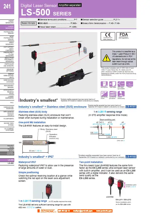
241LS-400FIBERSENSORSLASERSENSORSHUMAN MACHINEINTERFACESENERGY CONSUMPTIONVISUALIZATIONCOMPONENTSFA COMPONENTSMACHINE VISIONSYSTEMSUV CURINGSYSTEMSFeaturing stainless steel (SUS) enclosure that won’tbreak when bumped during installation or maintenance.(In STD amplifier response time mode)Unit: mm in Stainless steel (SUS) body 1 m 3.281 ft sensing rangeOne-point M6 installationFeaturing waterproof IP67 to allow use in the presenceof large amounts of water or dust.Two-point installationThe thru-beam type LS-H102 features the same formfactor as the EX-L200 series ultra-compact laser sensorwith built-in amplifier, and it can be used as an EX-L200series with a digital indicator. It also delivers the samebend quality as theEX-L200 series.The LS-H101 features an easy-to-install design.M6Body: Stainless steel(SUS)Operationindicator(receiver only)Actual size1 m 3.281 ft sensing range(In STD amplifier response time mode)The LS-H102 delivers sufficient sensing range for use with450 mm 17.717 in wafers.Check the optimal receiving location at a glance whilewatching the red spot on the beam axis adjustmentscreen.Simple positioningInstallation pitch13 mm 0.512 inEX-L211 / EX-L212LS-H102Same installation pitchas the EX-L200 series Waterproof IP67SEN TRONIC242LS-400FIBER SENSORS PHOTOELECTRIC SENSORS MICROPHOTOELECTRIC SENSORS AREASENSORS LIGHT CURTAINS /SAFETYCOMPONENTS PRESSURE / FLOWSENSORS INDUCTIVE PROXIMITY PLCHUMAN MACHINE INTERFACES ENERGY CONSUMPTION VISUALIZATION COMPONENTS FA COMPONENTS MACHINE VISION SYSTEMSUV CURING SYSTEMSIndustry’s smallest* + Thinnest profile* S mallest amplifier-separated type laser sensor head as of September 2013 based on research conducted by our companyLS-H201Coaxial designSmall, long-range spotEasy-to-see operation indicatorBy using a laser with high linearity in a coaxial design, the LS-H201 is able to deliver stable sensing in confined spaces as well as simple installation.The LS-H201 produces a spot with a diameter of 2 mm 0.079 in at a sensing range of up to 300 mm 11.811 in (in STD amplifier response time mode).The LS-H201’s operation indicator is visible from all directions.Featuring a 60% smaller design (by volume) than previous coaxial reflective models, our smallest unit is smaller in every dimension at just W8 × H23 × D18 mm W0.315 × H0.906 × D0.709 in (excluding indicators).0.315 in23mm ø2 mm ø0.079 in300 mm 11.811 inGasketLS-400FIBER SENSORS PHOTOELECTRICSENSORS MICROPHOTOELECTRICSENSORS AREA SENSORS LIGHT CURTAINS /SAFETY COMPONENTS PRESSURE /FLOW SENSORS INDUCTIVE PROXIMITY SENSORS PARTICULAR USE SENSORSSENSOR OPTIONS SIMPLE WIRE-SAVINGUNITS WIRE-SAVINGSYSTEMS MEASUREMENTSENSORS STATIC ELECTRICITYPREVENTION DEVICES LASER MARKERSPLCHUMAN MACHINEINTERFACES ENERGY CONSUMPTIONVISUALIZATION COMPONENTS FA COMPONENTS MACHINE VISIONSYSTEMS UV CURING SYSTEMSFX-500 series fiber sensor LS-500 series laser sensor0.315 in4 mm 0.157 inAmong industry’s fastest response times* 60 μs* A mplifier-separated type laser sensor amplifiers as ofSeptember 2013 based on research conducted by our company* S mallest amplifier-separated type laser sensor head as ofSeptember 2013 based on research conducted by our companyLS-501□Industry’s smallest* and thinnest designHorizontal symmetryFeaturing a simple system design process thanks to a light source that is placed in the center of the sensor head and a coaxial design.Engineered for maximum compatibility with fiber sensors in every aspect of its design, from form factor to operability, the LS-500 series delivers an environment that makes it easy to choose a laser sensor.The LS-H901 is even thinner than previous models, measuring just W8 × H23 (excluding indicators) × D18 mm W0.315 × H0.906 × D0.709 in .Maximum compatibility with fiber sensorsDetection of beam axis misalignmentDual outputs (self-diagnosis output)Stable sensing over the long term Logic operationsData bankThe LS-500 series features the same operation, menu displays, and form factor as the FX-500 series for increased compatibility with fiber sensors.The LS-500 series can detect any reduction in incident light intensity, for example due to the accumulation of dirt such as dust, and issue an alarm. Sensing output 2 can be set as self-diagnosis output. When you teach the threshold for sensing output 1, sensing output 2 is set accordingly, allowing you to shift the threshold by a previously set margin.The LS-500’s threshold-tracking function helpsmaintain stable sensing over the long term and reduce maintenance man-hours. The incident light intensity can be checked and the threshold automatically reset at a user-selected interval to track changes in light intensity due to environmental changes (such as dust, etc.) over extended periods of time. The LS-500’s ability to perform three logic operations (AND, OR, and XOR) on a standalone basis eliminates the need for a dedicated controller, cuts down onwiring, and lowers costs. This functionality can also be combined with the FX-500 series.Eight sets of amplifier settings can be stored in the unit’s built-in memory. The ability to save and load settings reduces workload when changing the setup in a multi-model production environment.LS-400PHOTO-ELECTRIC SENSORS MICRO PHOTO-ELECTRIC SENSORS AREA SENSORS LIGHT CURTAINS /SAFETY COMPONENTS PRESSURE / FLOW SENSORS INDUCTIVE PROXIMITY SENSORS PARTICULAR USE SENSORS SENSOR OPTIONS SIMPLE WIRE-SAVING UNITS WIRE-SAVING SYSTEMS MEASURE-MENT SENSORS STATIC ELECTRICITY PREVENTION DEVICES LASER MARKERS PLC HUMAN MACHINE INTERFACES ENERGY CONSUMPTION VISUALIZATION COMPONENTSFACOMPONENTS MACHINE VISION SYSTEMSUVCURING SYSTEMSORDER GUIDE056 222 38 18SEN TRONIC AG245Digital Laser Sensor LS-500SERIESLS-400FIBERSENSORSPHOTO-ELECTRICSENSORSMICROPHOTO-ELECTRICSENSORSAREASENSORSLIGHTCURTAINS /SAFETYCOMPONENTSPRESSURE /FLOWSENSORSINDUCTIVEPROXIMITYSENSORSPARTICULARUSESENSORSSENSOROPTIONSSIMPLEWIRE-SAVINGUNITSWIRE-SAVINGSYSTEMSMEASURE-MENTSENSORSSTATICELECTRICITYPREVENTIONDEVICESLASERMARKERSPLCHUMANMACHINEINTERFACESENERGYCONSUMPTIONVISUALIZATIONCOMPONENTSFACOMPONENTSMACHINEVISIONSYSTEMSUVCURINGSYSTEMSSensor head mounting bracketMaterial: Stainless steel (SUS304)Two M3 (length 14 mm 0.551 in)screws with washers [stainlesssteel (SUS304)] are attached.• MS-EXL2-5Fine-Rotatethrough360°Reflector• RF-310• RF-31Reflective tape9.2 mmAccessoriesMS-LS-1 (Sensor head mounting bracket)For LS-H201□ / LS-H901□mountingBack angledmountingRF-330 (Reflector)MS-EXL2-2 (Mounting plate for thru-beam type)Mounting plateMaterial: Stainless steel (SUS304)Two M2 (length 12 mm 0.472 in) screws with washers[stainless steel (SUS)] are attached.Material: Stainless steel (SUS)Material: Die-cast zinc alloyTwo M3 (length 14 mm 0.551 in) screws withwashers [stainless steel (SUS)], one M3 (length 10mm 0.394 in) hexagon-socket-head bolt [stainlesssteel (SUS)], and one M3 hexagon nut [stainlesssteel (SUS)] are attached.0.551 in) screws withwashers [stainless steel (SUS)] are attached.056 222 38 18*********************SEN TRONICAG246Digital Laser SensorLS-500SERIESLS-400FIBER SENSORS PHOTO-ELECTRIC SENSORS MICRO PHOTO-ELECTRIC SENSORS AREA SENSORS LIGHT CURTAINS /SAFETY COMPONENTS PRESSURE / FLOW SENSORS INDUCTIVE PROXIMITY SENSORS PARTICULAR USE SENSORS SENSOR OPTIONS SIMPLE WIRE-SAVING UNITSWIRE-SAVING SYSTEMS MEASURE-MENT SENSORS STATIC ELECTRICITY PREVENTION DEVICES LASER MARKERS PLC HUMAN MACHINE INTERFACES ENERGY CONSUMPTION VISUALIZATION COMPONENTS FACOMPONENTSMACHINE VISION SYSTEMS UVCURING SYSTEMSNotes: 1) Where measurement conditions have not been specified precisely, the conditions used were an ambient temperature of +23 °C +73.4 °F . 2) When using the thru-beam type LS-H101□ or LS-H102□, do not set the receiving light sensitivity (gctL) of the applicable LS-500 series amplifier to level2 or less. This is because there is a possibility of sensing becoming unstable.3) The sensing range of the coaxial reflective type sensor is specified for white non-glossy paper (100 × 100 mm 3.937 × 3.937 in ) as the object. 4) The sensing ranges for coaxial retroreflective type sensors are values for the RF-330 reflector. In addition, the sensing range is the possible settingrange for the reflector. The sensor can detect an object less than 0.01 m 0.033 ft away. Note that if there are white papers or specular objects near the sensor head, reflected light from these objects may be received. In such cases, use the amplifier unit’s receiving sensitivity function to lower thesensitivity, change the response time, or move the sensor head away from the target object. The incident light intensity may vary with the condition of the reflector surface. When using one of the applicable LS-500 series amplifiers, leave an adequate safety margin when setting the threshold.5) Make sure to confirm detection with an actual sensor before use. 6) This product complies with 21 CFR 1040.10 and 1040.11 Laser Notice No. 50, dated June 24, 2007, issued by CDRH (Center for Devices andRadiological Health) under the FDA (Food and Drug Administration). For details, refer to the Laser Notice No. 50.7) Cable cannot be extended.056 222 38 18*********************SEN TRONIC AG247Digital Laser Sensor LS-500SERIESLS-400FIBERSENSORSPHOTO-ELECTRICSENSORSMICROPHOTO-ELECTRICSENSORSAREASENSORSLIGHTCURTAINS /SAFETYCOMPONENTSPRESSURE /FLOWSENSORSINDUCTIVEPROXIMITYSENSORSPARTICULARUSESENSORSSENSOROPTIONSSIMPLEWIRE-SAVINGUNITSWIRE-SAVINGSYSTEMSMEASURE-MENTSENSORSSTATICELECTRICITYPREVENTIONDEVICESLASERMARKERSPLCHUMANMACHINEINTERFACESENERGYCONSUMPTIONVISUALIZATIONCOMPONENTSFACOMPONENTSMACHINEVISIONSYSTEMSUVCURINGSYSTEMS2) 25 mA if 5 or more amplifier are connected in cascade (excluding cable extension).3) Number of units that can be mounted close together: 0 for H-SP; 2 for FAST; 4 for STD, LONG, U-LG, or HYPR4) Select either sensing output 2 or external input as the connector type.056 222 38 18*********************SEN TRONICAG248Digital Laser SensorLS-500SERIESLS-400FIBER SENSORS PHOTO-ELECTRIC SENSORSMICRO PHOTO-ELECTRIC SENSORS AREA SENSORSLIGHTCURTAINS /SAFETY COMPONENTSPRESSURE /FLOW SENSORS INDUCTIVE PROXIMITY SENSORSPARTICULAR USE SENSORS SENSOR OPTIONS SIMPLE WIRE-SAVING UNITS WIRE-SAVING SYSTEMS MEASURE-MENT SENSORS STATIC ELECTRICITY PREVENTION DEVICES LASER MARKERS PLCHUMAN MACHINE INTERFACES ENERGY CONSUMPTION VISUALIZATION COMPONENTS FACOMPONENTSMACHINE VISION SYSTEMS UVCURING SYSTEMSSymbols ...D 1, D 2, D 3, D 4: Reverse supply polarity protection diodeZ D1, Z D2: Surge absorption zener diode Tr 1, Tr 2 : NPN output transistor%Notes: 1) The quick-connection sub cable does not have +V (brown) and 0 V (blue).The power is supplied from the connector of the main cable.2) Wiring when sensing output 2 is selected is shown with solid lines. Wiringwhen external input is selected is shown with broken lines.NPN output typeConnector typeCable typeI/O circuit diagramsNPN output typePNP output typeNotes: 1) The quick-connection sub cable does not have brown lead wire and blue leadwire. The power is supplied from the connector of the main cable.2) The quick-connection cable does not have gray or pink lead wires.Wiring diagramsTerminal layout of connector typeColor code of cable type / quick-connection cable Color code of cable type / quick-connection cable Notes: 1) The quick-connection sub cable does not have brown lead wire and blue leadwire. The power is supplied from the connector of the main cable.2) The quick-connection cable does not have gray or pink lead wires.* Connector for amplifier (CN-EP4) pin position%%Notes: 1) The quick-connection sub cable does not have +V (brown) and 0 V (blue).The power is supplied from the connector of the main cable.2) Wiring when sensing output 2 is selected is shown with solid lines. Wiringwhen external input is selected is shown with broken lines.%%%PNP output typeConnector typeCable typeSymbols ...D 1, D 2, D 3, D 4: Reverse supply polarity protection diodeZ D1, Z D2: Surge absorption zener diode Tr 1, Tr 2 : PNP output transistor056 222 38 18*********************SEN TRONIC AG249Digital Laser Sensor LS-500SERIESLS-400FIBERSENSORSPHOTO-ELECTRICSENSORSMICROPHOTO-ELECTRICSENSORSAREASENSORSLIGHTCURTAINS /SAFETYCOMPONENTSPRESSURE /FLOWSENSORSINDUCTIVEPROXIMITYSENSORSPARTICULARUSESENSORSSENSOROPTIONSSIMPLEWIRE-SAVINGUNITSWIRE-SAVINGSYSTEMSMEASURE-MENTSENSORSSTATICELECTRICITYPREVENTIONDEVICESLASERMARKERSPLCHUMANMACHINEINTERFACESENERGYCONSUMPTIONVISUALIZATIONCOMPONENTSFACOMPONENTSMACHINEVISIONSYSTEMSUVCURINGSYSTEMSMetal plateAccessory forMS-EXL2-1Cautions for laser beamsPart description (Amplifier)MountingAmplifierLS-H201□, LS-H901□<How to mount the amplifier>(1) F it the rear part of the mountingsection of the amplifier on a 35 mm1.378 in width DIN rail.(2) P ress down the rear part of themounting section of the unit on the 35 mm 1.378 in widthDIN rail and fit the front part of the mounting section tothe DIN rail.<How to mount the sensor head>(1) I nsert the sensor headconnector into the inlet until itclicks.(2) Fit the cover to the connector.<How to remove the amplifier>(1) Push the amplifier forward.(2) L ift up the front part of theamplifier to remove it.Note: B e careful. If the front part is lifted without pushing the amplifier forward,Sensor headLS-H101□• The tightening torqueshould be 0.98 N·m or less.LS-H102□• In case mounting this product,use a metal plate MS-EXL2-2(accessory).• The tightening torque should be0.5 N·m or less with M3 screws.<Not requiring the metal plate><Requiring the metal plate>• In case using the dedicated sensor head mountingbracket MS-EXL2-1 (optional) when mounting thisproduct, the metal plate MS-EXL2-2 (accessory) isrequired depending on the mounting direction. Mount asthe diagram below indicates.• The tightening torqueshould be 0.5 N·m orless.• When placing the sensorhead horizontally orvertically, the reflectormust also be positionedhorizontally or verticallyas shown in Fig. 1 below. I f the sensor head is placed horizontallyor vertically but the reflector is tilted as shown in Fig. 2 below, thereflection amount will decrease, which may cause unstable detection.Safety standards for laser beam products• A laser beam can harm human being’s eyes, skin, etc.,because of its high energy density. IEC has classifiedlaser products according to the degree of hazard and thestipulated safety requirements. LS-H□ is classified asClass 1 laser.Classification by IEC 60825-1width DIN railconnector(Purchase separately)Safe use of laser products• For the purpose of preventing users from sufferinginjuries by laser products, IEC 60825-1 (Safety of laserproducts). Kindly check the standards before use.(Refer to About laser beam.)* T his product complies with 21 CFR 1040.10 and 1040.11 Laser NoticeNo. 50, dated June 24, 2007, issued by CDRH (Center for Devices andRadiological Health) under the FDA (Food and Drug Administration).056 222 38 18*********************SEN TRONICAG250Digital Laser SensorLS-500SERIESLS-400FIBER SENSORS PHOTO-ELECTRIC SENSORS MICRO PHOTO-ELECTRIC SENSORS AREA SENSORS LIGHT CURTAINS /SAFETY COMPONENTS PRESSURE / FLOW SENSORS INDUCTIVE PROXIMITY SENSORS PARTICULAR USE SENSORS SENSOR OPTIONS SIMPLE WIRE-SAVING UNITS WIRE-SAVING SYSTEMS MEASURE-MENT SENSORS STATIC ELECTRICITY PREVENTION DEVICES LASER MARKERS PLC HUMAN MACHINE INTERFACESENERGY CONSUMPTION VISUALIZATION COMPONENTS FACOMPONENTSMACHINE VISION SYSTEMS UVCURING SYSTEMSFig. 1 Proper positioningWhen placing the sensor head horizontally or vertically, the reflector shall also be positioned horizontally or vertically.Fig. 2 Improper positioningWhen placing the reflector tilted even when the sensor head is positioned horizontally or vertically.Wiring• Make sure that the power supply is off while wiring.• Verify that the supply voltage variation is within the rating.• Take care that if a voltage exceeding the rated range is applied, or if an AC power supply is directly connected, the sensor may get burnt or damaged.• If power is supplied from a commercial switching regulator, ensure that the frame ground (F.G.) terminal of the power supply is connected to an actual ground.• Make sure to use the optional quick-connection cable for the connection of the amplifier [connector type LS-501(P )]. Extension up to total 100 m 328.084 ft is possible with 0.3 mm 2, or more, cable. However, in order to reduce noise, make the wiring as short as possible. Set the supply voltage after considering the voltage drop caused by the cable’s resistance.Others• Do not use during the initial transient time (0.5 sec. approx.) after the power supply is switched on.• B ecause the sensitivity is higher in U-LG and HYPER modes than in other modes, it can be more easily affected byextraneous noise. Check the operating environment before use.Amplifier LS-501 LS-501PAmplifierLS-501-C LS-501P-CCN-74-C1 CN-74-C2 CN-74-C5Main cable (Optional)Sub cable (Optional)CN-72-C1 CN-72-C2 CN-72-C5When adding units, wiring length must not exceed 50 m 164.042 ft (for 5 to 8 amplifiers) or 20 m 65.617 ft (for 9 to 16 amplifiers). <Correct><Incorrect>056 222 38 18*********************SEN TRONIC AG251Digital Laser Sensor LS-500SERIESLS-400FIBERSENSORSPHOTO-ELECTRICSENSORSMICROPHOTO-ELECTRICSENSORSAREASENSORSLIGHTCURTAINS /SAFETYCOMPONENTSPRESSURE /FLOWSENSORSINDUCTIVEPROXIMITYSENSORSPARTICULARUSESENSORSSENSOROPTIONSSIMPLEWIRE-SAVINGUNITSWIRE-SAVINGSYSTEMSMEASURE-MENTSENSORSSTATICELECTRICITYPREVENTIONDEVICESLASERMARKERSPLCHUMANMACHINEINTERFACESENERGYCONSUMPTIONVISUALIZATIONCOMPONENTSFACOMPONENTSMACHINEVISIONSYSTEMSUVCURINGSYSTEMSLS-H101□Sensor headNote: Not incorporated on the emitter.Sensor headLS-H102□Note: Not incorporated on the emitter.LS-H201□ LS-H901□Sensor head3.156.90.8MS-DIN-E End plate (Optional)Material: Acrylic (Reflector)ABS (Base)0.1650.217Reflector (Accessory for LS-H901□)RF-330Material: Acrylic (Reflector)ABS (Base)RF-310Reflector (Optional)Reflective tape (Optional)RF-33 RF-318.5Material: Cold rolled carbon steel (SPCC)(Uni-chrome plated)MS-DIN-2Amplifier mounting bracket (Optional) 056 222 38 18*********************SEN TRONICAG252Digital Laser SensorLS-500SERIESLS-400FIBER SENSORS PHOTO-ELECTRIC SENSORS MICRO PHOTO-ELECTRIC SENSORS AREA SENSORS LIGHT CURTAINS /SAFETY COMPONENTS PRESSURE / FLOW SENSORS INDUCTIVE PROXIMITY SENSORS PARTICULAR USE SENSORS SENSOR OPTIONS SIMPLE WIRE-SAVING UNITS WIRE-SAVING SYSTEMS MEASURE-MENT SENSORS STATIC ELECTRICITY PREVENTION DEVICES LASER MARKERSPLC HUMAN MACHINE INTERFACES ENERGY CONSUMPTIONVISUALIZATION COMPONENTSFACOMPONENTS MACHINE VISION SYSTEMS UVCURING SYSTEMSRear mounting bracketFoot angled mounting bracketUniversal sensor mounting bracketAssembly dimensionsMaterial: Stainless steel (SUS304)Two M3 (length 14 mm 0.551 in ) screws with washers [stainless steel (SUS304)] are attached.Material: Stainless steel (SUS304)Note: Without using the mounting plate,beam misalignment may occur.Mounting drawing with the emitter of LS-H102□Assembly dimensionsMounting drawing with the receiver of LS-H102□Note: Screws are not attached. Purchase separately.0.0590.0390.10233-M3 × 0.5 14 Note: This is the adjustable range of the movable part.Mounting drawing with the receiver of LS-H102□112 8 R13 t 1.5 MS-LS-1Sensor head mounting bracket (Accessory for LS-H201□, LS-H901□)Sensor head mounting bracket for LS-H102□ (Optional)MS-EXL2-1MS-EXL2-2Mounting plate (Accessory for LS-H102□)Sensor head mounting bracket for LS-H102□ (Optional)MS-EXL2-4Sensor head mounting bracket for LS-H102□ (Optional)MS-EXL2-5Material: Stainless steel (SUS304)Two M3 (length 14 mm 0.551 in ) screws with washers [stainless steel (SUS304)] are attached.Material: Die-cast zinc alloyTwo M3 (length 14 mm 0.551 in ) screws with washers, one M3 (length 10 mm 0.394 in ) hexagon socket-head bolt [stainless steel (SUS)], and one M3 hexagon nut [stainless steel (SUS)] are attached.056 222 38 18*********************SEN TRONIC AG。
欧姆龙光电开关说明书1. 引言欧姆龙光电开关是一种利用光电传感器技术实现的开关设备,通过检测光线的变化来判断是否触发开关动作。
本说明书将详细介绍欧姆龙光电开关的技术原理、使用方法、注意事项以及维护保养等内容,以帮助用户合理、安全地使用该设备。
2. 技术原理欧姆龙光电开关采用了光电传感器技术,在光电传感器中,包含了一对光源和光敏元件。
当遮挡物体经过检测区域时,光敏元件将接收到的光信号发生变化,从而触发开关动作。
光电开关通常有两种工作方式:逻辑输出和模拟输出,具体的输出信号可以根据用户需求进行设置。
3. 使用方法a)安装根据实际需求,将光电开关安装到需要检测的位置上,确保光敏元件可以正常接收到被检测物体通过的光信号。
注意避免外部光源对光敏元件产生干扰,可以通过合理选择安装位置和使用遮光罩等方式来减少干扰。
b)连接将光电开关与电路连接,确保电路连接正确且稳定。
通常光电开关需要使用直流电源进行供电,电压范围根据具体型号来确定。
c)设置根据实际应用需求,设置光电开关的工作方式、触发灵敏度等参数。
欧姆龙光电开关通常提供了相应的参数调节装置,用户可以根据需要进行调整。
d)测试完成安装、连接和设置后,进行测试以确保光电开关正常工作。
可以通过手动触发被检测物体通过检测区域,观察开关的触发情况,根据实际需求进行调整。
4. 注意事项a)使用过程中请确保电源电压符合设备要求,避免超过额定电压范围。
b)在使用过程中请避免将光电开关安装在高温、潮湿等有害环境中,以免影响设备的正常工作。
c)避免遮挡光敏元件,在使用过程中请确保光敏元件处于正常工作状态,避免被阻挡物体遮挡。
d)避免外部光源干扰,在安装过程中请注意避免强光直射到光敏元件上,可以使用遮光罩等方式来减少光源干扰。
e)检查设备连接是否牢固,确保所有连接处都紧固可靠,避免松动引起的工作异常。
f)如设备出现故障,请及时联系专业维修人员进行处理,避免私自拆解修理。
5. 维护保养a)定期清洁光敏元件,可以使用干净的棉签轻轻擦拭。
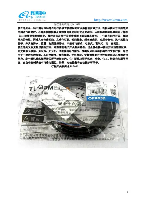
行程开关欧姆龙hl-5030
接近开关是一种无需与运动部件进行机械直接接触而可以操作的位置开关,当物体接近开关的感应面到动作距离时,不需要机械接触及施加任何压力即可使开关动作,从而驱动直流电器或给计算机(plc)装置提供控制指令。
接近开关是种开关型传感器(即无触点开关),它既有行程开关、微动开关的特性,同时具有传感性能,且动作可靠,性能稳定,频率响应快,应用寿命长,抗干扰能力强等、并具有防水、防震、耐腐蚀等特点。
产品有电感式、电容式、霍尔式、交、直流型。
接近开关又称无触点接近开关,是理想的电子开关量传感器。
当金属检测体接近开关的感应区域,开关就能无接触,无压力、无火花、迅速发出电气指令,准确反应出运动机构的位置和行程,即使用于一般的行程控制,其定位精度、操作频率、使用寿命、安装调整的方便性和对恶劣环境的适用能力,是一般机械式行程开关所不能相比的。
它广泛地应用于机床、冶金、化工、轻纺和印刷等行业。
在自动控制系统中可作为限位、计数、定位控制和自动保护环节等。
行程开关欧姆龙hl-5030。
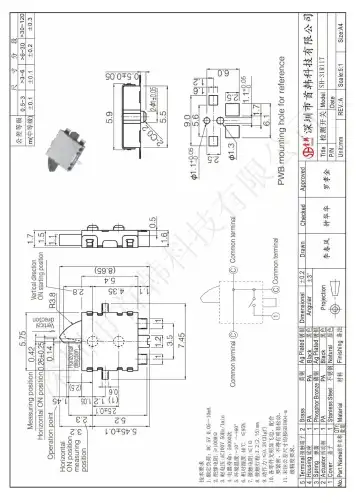
深圳市首韩科技有限公司限位开关深圳市首韩科技有限公司SHENZHEN SHOUHAN TECHNOLOGYCO.,LTDTel:*************Fax:*************客户Customer:产品名称Project:规格型号Part No:贵公司承认印Approal slgnatures料号/Part No.签章/Signatures日期Date:拟制/Drawn 李春风审核/Check 钟华华批准/Approved罗孝金1深圳市首韩科技有限SH-31R 11T1. 一般特性General Characteristics正常温度: 5℃~35℃ 相对湿度: 45%~85% 1.1 额定值(Rating Value): DC 5V 10mA1.2 工作温度(Work Temperature Range): -10℃ ~ 60℃1.3 存贮温度(Store Temperature Range): -20℃ ~ 80℃1.4 正常测试条件(未有特殊说明量测在以下条件进行):General test condition (Tests and measurements shall be made under the following standard conditions unless otherwise specified):RH 气 压: 8,600~10,600帕Temperature: 5℃~35℃ Relative humidity: 45%~85% Air pressure: 8,600~10,600 pa2. 产品外观及尺寸要求 Appearance & Dimension Requirement2.1 产品外形结构紧凑,无配合不良.The structure of product is compact, and assembly of parts has no badness.2.2 产品塑胶部件无严重缩水、披锋、欠注、斑点、破损或变形现象.The plastic parts of product have no serious defects such as very serious shrink, scarcity,fleck, disrepair, transmutation, etc.2.3 产品引脚和外壳无严重氧化、脏污、变形、毛刺或电镀不良.Lead feet and shell have no serious defects such as oxidation, smudge, disrepair, burr, defects on plating.2.4 开关操作顺畅,节奏感强,无明显卡塞现象。
欧姆龙光电开关说明书欧姆龙光电开关说明书欧姆龙光电开关是一种智能化的电子元件,其主要作用是通过光电原理进行物体检测和位置控制。
本说明书将详细介绍欧姆龙光电开关的特点、工作原理、应用场景及使用方法。
一、特点:1.欧姆龙光电开关是一种高精度、高稳定性、可靠性极强的电子元件。
2.具有光电隔离、噪声抑制、防护等多种功能,适用于各种复杂环境。
3.采用LED和光敏二极管作为光电转换元件,光电效率高,响应速度快。
4.外部封装材料采用耐磨损、耐腐蚀等工程塑料,有很好的耐用性。
二、工作原理:欧姆龙光电开关通过内部光电器件产生光束,当光束遇到物体时,被物体反射后重新聚焦到另一端的光电器件中,从而完成物体的检测。
欧姆龙光电开关具有光电隔离功能,内部电路和外部电路之间采用光耦隔离,有效地防止外部杂音对内部电路造成的干扰。
三、应用场景:欧姆龙光电开关广泛应用于机械、自动化控制、制造业等领域,主要用于非接触式物体检测、位置控制、安全门的监测等方面。
1.非接触式物体检测:无需接触被检测物体,避免了传统机械开关导致的松动、震动等问题,可以检测各种形状、大小、材质的物体。
2.位置控制:通过欧姆龙光电开关的探头来确认物体的位置,可以实现高精度的位置控制。
3.安全门监测:应用于工业机器人、机床等设备的安全门监测,如果关门后开关没有断开,则不允许机器运转,保证工作安全。
四、使用方法:欧姆龙光电开关使用便捷,安装简单。
1.安装:根据欧姆龙光电开关的不同型号和尺寸进行选型,将开关固定在合适的位置,光电探头对准被检测物体即可。
2.电路连接:按照说明书的接线图进行连接,注意接口与电压等参数的匹配。
3.调试:路电线接好后进行检测,根据不同的检测需求进行参数调整,使光电开关的工作符合工作要求。
总之,欧姆龙光电开关是一种高精度、高稳定、安全可靠的电子元件,在工业、汽车、航空等领域中得到了广泛的应用。
相信在未来的发展中,欧姆龙光电开关会继续引领各领域的技术发展和应用进步,推动人类社会的不断发展。
1B3W-9Illuminated Tactile SwitchesCompact Illuminated Tactile Switch with 2 LEDs•Compact construction 10 × 10 × 11 mm (W × D ×H) and 12 × 12 × 11 mm (W × D × H) with bright and uniform illumination.•Three-color illumination (red LED + green LED =orange).•Standard force (1.57 N) and high-force (2.26 N)models.■Features■Model Number Legend1.Cap width 0:10 × 10 mm 1:12 × 12 mm2.Operating force0:Standard (OF = 1.57 N {160 gf})2:High-force (OF = 2.26 N {230 gf})3.LED colorR:Red G:GreenHG:Green (high brightness)Y:Y ellow B:BlueRG:Red + Green (Combination of LED colors)RB:Red + Blue (Combination of LED colors)4.No. of LEDs 1:12:25.CapR:Red G:Green Y:Y ellow B:BlueC:Transparent N:Milky whiteNote:Detail information of ordering can be found on p.2.RoHS Compliant11 mm × D■List of Models10 × 10-mm SwitchesStandard force High-force Force LED color No. ofLEDsCap color ModelStandard force(OF = 1.57 N)Blue1Blue B3W-9000-B1B1Transparent B3W-9000-B1C1Milky white B3W-9000-B1N2Blue B3W-9000-B2B2Transparent B3W-9000-B2C2Milky white B3W-9000-B2NGreen1Transparent B3W-9000-G1C1Green B3W-9000-G1G1Milky white B3W-9000-G1N2Transparent B3W-9000-G2C2Green B3W-9000-G2G2Milky white B3W-9000-G2NGreen(highbrightness)1Transparent B3W-9000-HG1C1Green B3W-9000-HG1G1Milky white B3W-9000-HG1N2Transparent B3W-9000-HG2C2Green B3W-9000-HG2G2Milky white B3W-9000-HG2NRed1Transparent B3W-9000-R1C1Milky white B3W-9000-R1N1Red B3W-9000-R1R2Transparent B3W-9000-R2C2Milky white B3W-9000-R2N2Red B3W-9000-R2RRed +Green2Transparent B3W-9000-RG2C2Milky white B3W-9000-RG2NRed + Highbrightgreen2Transparent B3W-9000-RHG2CRed + Blue2Transparent B3W-9000-RB2CYellow1Transparent B3W-9000-Y1C1Milky white B3W-9000-Y1N1Yellow B3W-9000-Y1Y2Transparent B3W-9000-Y2C2Milky white B3W-9000-Y2N2Yellow B3W-9000-Y2YForce LED color No. ofLEDsCap color ModelHigh-force(OF = 2.26 N)Blue1Blue B3W-9002-B1B1Transparent B3W-9002-B1C1Milky white B3W-9002-B1N2Blue B3W-9002-B2B2Transparent B3W-9002-B2C2Milky white B3W-9002-B2NGreen1Transparent B3W-9002-G1C1Green B3W-9002-G1G1Milky white B3W-9002-G1N2Transparent B3W-9002-G2C2Green B3W-9002-G2G2Milky white B3W-9002-G2NGreen(highbrightness)1Transparent B3W-9002-HG1C1Green B3W-9002-HG1G1Milky white B3W-9002-HG1N2Transparent B3W-9002-HG2C2Green B3W-9002-HG2G2Milky white B3W-9002-HG2NRed1Transparent B3W-9002-R1C1Milky white B3W-9002-R1N1Red B3W-9002-R1R2Transparent B3W-9002-R2C2Milky white B3W-9002-R2N2Red B3W-9002-R2RRed +Green2Transparent B3W-9002-RG2C2Milky white B3W-9002-RG2NRed + Highbrightgreen2Transparent B3W-9002-RHG2CRed + Blue2Transparent B3W-9002-RB2CYellow1Transparent B3W-9002-Y1C1Milky white B3W-9002-Y1N1Yellow B3W-9002-Y1Y2Transparent B3W-9002-Y2C2Milky white B3W-9002-Y2N2Yellow B3W-9002-Y2Y2312 × 12-mm SwitchesStandard forceHigh-force■Ratings/Characteristics (Same for Both Standard and High-force Switches)■Operating CharacteristicsForce LED color No. of LEDs Cap color Model Standard force(OF = 1.57 N)Blue (high brightness)1Blue B3W-9010-B1B 1Milky white B3W-9010-B1N 2Blue B3W-9010-B2B 2Milky white B3W-9010-B2N Green1Green B3W-9010-G1G 1Milky white B3W-9010-G1N 2Green B3W-9010-G2G 2Milky white B3W-9010-G2N Green (highbrightness)1Green B3W-9010-HG1G 1Milky white B3W-9010-HG1N 2Green B3W-9010-HG2G 2Milky white B3W-9010-HG2N Red1Red B3W-9010-R1R 1Milky white B3W-9010-R1N 2Red B3W-9010-R2R 2Milky white B3W-9010-R2N Red + Green 2Milky white B3W-9010-RG2N Red + High bright green 2Milky whiteB3W-9010-RHG2NRed + Blue 2Milky white B3W-9010-RB2N Yellow1Yellow B3W-9010-Y1Y 1Milky white B3W-9010-Y1N 2Yellow B3W-9010-Y2Y 2Milky whiteB3W-9010-Y2NForceLED colorNo. of LEDs Cap color Model High-force (OF = 2.26 N)Blue 1Blue B3W-9012-B1B 1Milky white B3W-9012-B1N 2Blue B3W-9012-B2B 2Milky white B3W-9012-B2N Green 1Green B3W-9012-G1G 1Milky white B3W-9012-G1N 2Green B3W-9012-G2G 2Milky white B3W-9012-G2N Green (high bright-ness)1Green B3W-9012-HG1G 1Milky white B3W-9012-HG1N 2Green B3W-9012-HG2G 2Milky white B3W-9012-HG2N Red1Red B3W-9012-R1R 1Milky white B3W-9012-R1N 2Red B3W-9012-R2R 2Milky white B3W-9012-R2N Red + Green2Milky white B3W-9012-RG2N Red + High bright green 2Milky whiteB3W-9012-RHG2NRed + Blue2Milky white B3W-9012-RB2N Yellow1Yellow B3W-9012-Y1Y 1Milky white B3W-9012-Y1N 2Yellow B3W-9012-Y2Y 2Milky whiteB3W-9012-Y2NRatings1 to 50 mA, 5 to 24 VDC (resistive load)Ambient operating temperature −25°C to +70°C at 60% max. humidity (with no icing or condensation)Ambient operating humidity 35% to 85% (at +5 to +35°C)Contact form SPST-NOContact resistance 100 m Ω max. (initial value) (rated: 1 mA, 5 VDC)Insulation resistance 100 M Ω min. (at 250 VDC)Dielectric strength 500 VAC, 50/60 Hz for 1 min Bounce time 5 ms max.Vibration resistance Malfunction: 10 to 55 Hz, 1.5 mm double amplitude Shock resistance Destruction: 1,000 m/s 2 {approx. 100 G} max.Malfunction: 100 m/s 2 {approx. 10 G} max.DurabilitySwitch section1.57 N (standard force):1,000,000 operations min.2.26 N (high-force):300,000 operations min.ItemStandard-force Switches (B3W-90@0)High-force Switches(B3W-90@2)Operating force (OF) 1.57 N {160 gf} max. 2.26 N {230 gf} max.Releasing force (RF)0.2 N {20 gf} min.0.49 N {50 gf} min.Pretravel (PT)0.25+0.2/−0.1 mm4■LED Specifications(Ambient temperature Ta = 25°C)Note:For Switches with two LEDs, red and green, the recommended operating current is 12 mA for the red and 20 mA for the green LED for application with three-color illumination.■LEDs●Forward current reduction curve●Forward current and forward voltage curvesNote:1.Make sure that the polarity of the LEDs is correct. The polarity is not indicated on the Switch, but the positive pole is located on the back surface of the Switch on the side with the OMRON mark.2.Connect limiting resistors to the LEDs. The Switch does not have built-in limiting resistors, so satisfy the LED characteristics by obtaining the limiting resistance according to the following formula based on the voltage to be used.LED colorRedGreenGreen (high brightness)YellowBlueMaximum operating current I FM 27 mA 27 mA 27 mA 45 mA 27 mA Recommended operating current I F 20 mA 20 mA 10 mA 20 mA 10 mA Forward voltage (standard value) V F 1.8 V 2.1 V 3.7 V 2.4 V 3.7 V Maximum reverse voltage V R 5 V5 V5 V5 V5 VAmbient operating temperature−25°C to 70°C■Dimensions(Unit: mm)1 LED TypesB3W-900@-@1@B3W-901@-@1@2 LED TypesB3W-900@-@2@B3W-901@-@2@Note:Unless otherwise specified, a tolerance of ±0.4 mm applies to all dimensions. No terminal numbers are indicated on the Switches.56■AccessoriesB3W-9@@-F @Text Combination FilmsText Combination Films for B3W-9 Illuminated Tactile Switches•Display two different labels in combination with a 2-LED B3W-9 Switch. •Color combinations: Red/Green or Red/Blue■Model Number Legend1.ColorR:Red 2.ColorB:Blue G:Green3.Color and text combinationF1:Red OFFBlue or green ONF2:Red (OFF)Blue or green (ON)F3:Red (C L OSE)Blue or green (OPEN)F4:RedBlue or green F5:RedBlue or green Note:1.Five text combinations are available.2.Films can also be customized with other text for 50sheets (1,250 films) per lot. Delivery time is approxi-mately five weeks. (Ask your OMRON representative for details.)■Recommended B3W-9 Switches■Minimum Order25 films/sheetB3W-9 Films are sold in units of 25 films. Orders must be made in multiples of 25 (the quantity per sheet).Note:Text Combination Films are sold without the Switches. Or-der one of the above models of B3W-9 Illuminated Tactile Switches separately.Operating force2-LED SwitchesRed/BlueRed/Bright green Standard-force Switches B3W-9000-RB2C B3W-9000-RHG2C High-force Switches B3W-9002-RB2CB3W-9002-RHG2C■Safety PrecautionsNote:Refer to Safety Precautions in Tactile Switches (Cat. No. X037) for details on general safety precautions.■Precautions for Correct UseElectrical StandardsUse the Switch within the rated voltage and current ranges, other-wise the Switch may have a shortened life expectancy, radiate heat, or burn out. This particularly applies to the instantaneous voltages and currents when switching.Soldering1. Soldering Precautions•Before any kind of soldering, test to confirm that soldering can be performed properly. Otherwise the Switch may be deformed by the soldering heat depending on the type of PCB, pattern, or lands of the PCB.•Do not solder the Switch more than twice, including rectification soldering. Wait for at least five minutes between the first and sec-ond soldering to allow the temperature to return to normal. Con-tinuous soldering may cause the casing to melt or deteriorate the Switch characteristics.2. Automatic Soldering Baths (Wave Soldering)•Soldering temperature: 260°C max.•Soldering time: 5 s max. for a 1.6-mm thick single-side PCB •Preheating temperature: 100°C max. (ambient temperature)•Preheating time: Within 60 s•PrecautionsMake sure that no flux will rise above the level of the PCB. Also make sure that flux is not applied to the switch terminals or to the mounting surface of the PCB.If flux overflows onto the mounting surface of the PCB, it may en-ter the Switch and cause a malfunction.3. Manual Soldering•Soldering temperature: 350°C max. at the tip of the soldering iron •Soldering time: 3 s max. for a 1.6-mm thick, single-side PCB •Precautions:Before soldering the Switch on a PCB, make sure that there is no unnecessary space between theSwitch and the PCB.WashingStandard Switches are not sealed, and cannot be washed. Doing so will cause the washing agent, together with flux or dust parti-cles on the PCB, to enter the Switch, resulting in malfunction. PCBsThe Switch is designed for a 1.6-mm thick, single-side PCB. Using PCBs with a different thickness or using double-sided, through-hole PCBs may result in loose mounting, improper inser-tion, or poor heat resistance in soldering. These effects will occur, depending on the type of holes and patterns of the PCB. There-fore, it is recommended that a verification test is conducted before use. Handling1. Usage EnvironmentBefore installing the Switch, make sure that the area of installa-tion is not subject to corrosive gases emitted from surrounding parts.Do not use in areas subject to high temperatures, high humidity, or toxic gases such as sulfuric gas (H2S, SO2), ammonia gas (NH3), nitric gas (HNO3), or chlorine gas (CI2). It can cause corro-sive damage to the contacts and result in malfunction.If there is silicon in the atmosphere, it may stop the contacts from functioning properly.If silicon products, such as silicon oil, silicon filler, or silicon wires, are used in the surrounding area, install a contact protection cir-cuit to prevent arching or remove the silicon source.The following situations may cause water to enter inside the Switch, resulting in a malfunction due to contact failure or corro-sion.•Using the Switch in an outdoor environment where it is exposed to water drops for an extended period of time.•Using the Switch in an underwater setting where it is subject to strong water pressure.Do not use Switches that have been dropped. The mating section or other internal parts may be damaged, resulting in malfunction. OperationDo not repeatedly operate the Switch with excessive force. Apply-ing excessive pressure or applying additional force after the plunger has stopped may deform the disk spring of the Switch, resulting in malfunction.Be sure to set up the Switch so that the plunger will operate in a straight vertical line.If the plunger is pressed of-center or from an angle it may cause deformation or damage to some parts. This may result in deterio-ration of durability or malfunction.Dust ProtectionDo not install or use Switches in dust-prone environments. If a Switch must be used in this kind of environment, use a protective sheet or take other measures to protect it against dust.Note:Switches with high-brightness green (HG) or blue (B) LEDs are susceptible to static electricity. Be careful whenhandling a Switch with these LEDs as it may cause theSwitch to breakdown.7Removing the Cap1.Hold the cap at the side away from the mating section. Pullstraight up.2.Do not remove the cap while the Switch is mounted. Doingso will apply force to the soldered section and LEDs, result-ing in malfunction.Placing the Cap on the SwitchHold the Cap at the side away from the mating section. Push straight down until the mating section meets.Removing the CapThe Cap can be removed up to two times. Excessively removing the Cap will cause the mating section to become weak, resulting the operating section not mating completely or the Cap may fall off.Film DimensionsDimensions of the film are shown below. The thickness is 0.2 mm.Storage PrecautionsStorage EnvironmentT o prevent degradation, such as discoloration, of the terminals during storage, do not store the Switch in locations that are sub-ject to the following conditions.1. High temperature or humidity2. Corrosive gases3. Direct sunlightStorage conditionStore the Switches in the packaging box.After the packaging box is opened, use the contents as quickly as possible. When storing leftover parts, make sure that appropriate measures are taken against humidity and corrosive gases. Agreement of Product UseComply with the usage, storage, and disposal conditions speci-fied by OMRON as outlined in the precautions in the product datasheet and specifications.Correct IncorrectCorrectIncorrect。
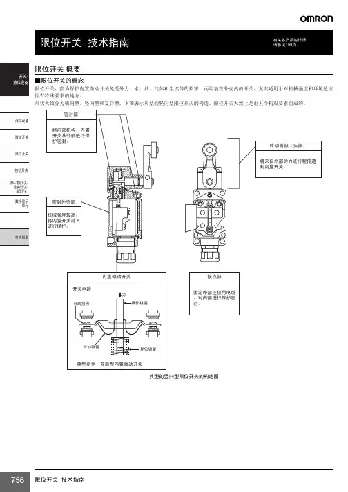
小型重载限位开关D4A-□N 291商品选择 ……………………200共通注意事项 ..................214技术指南 ........................709用语说明 (759)相关信息小型重载限位开关D4A-□N密封性、抗冲击性、强度进一步提高后的小型重载限位开关• 进一步强化旋转轴部位的双重密封结构, 通过密封垫完全包裹方式等来确保密封性 (取得UL 、NEMA3、4、4X 、6P 、12、13)。
• 温度规格范围大(-40~+100℃ :标准型)。
• 还另外备有在抗药性上发挥威力的氟橡胶密封型。
• 采用了将维护时的时间损失减少到最小的组件安装方式。
• 提供可实现各种复合动作的4回路双断型。
• 取得 UL 、CSA 、CCC 规格。
(关于认定型号、请来电咨询)请参见304~305页的「请正确使用」和 214页的「限位开关共通注意事项」。
型号构成■型号标准D4A-□□□□N(安装形式)① ② ③*1.头部请使用D4A-0017N 专用头部。
*2.头部请使用D4A-0018N 专用头部。
注.还备有氟橡胶密封型,请另外垂询。
①插座盒1 :1/2-14NPT 导管口(2回路双断型)2 :1/2-14NPT 导管口(4回路双断型)3 :G 1/2导管口(2回路双断型)4 : G 1/2导管口(4回路双断型)②开关盒1 :2回路双断型、无显示灯3 :2回路双断型、氖灯E :2回路双断型、LED (DC24V 漏电流1.3mA )5 : 4回路双断型、同时动作,无显示灯7 :4回路双断型、时序动作,无显示灯*19 :4回路双断型、中心、中线动作,无显示灯*2L :4回路双断型、同时动作,氖灯P : 4回路双断型、同时动作,LED③头部01:旋转摆杆型、标准型02:旋转摆杆型、高灵敏度型03:旋转摆杆型、轻动作型04:旋转摆杆型、高灵敏度轻动作型05:旋转摆杆型、保持型17: 旋转摆杆型、时序动作型18:旋转摆杆型、中心・中线动作型06:侧面・柱塞型、标准型 07-V :侧面・柱塞型、垂直滚珠型07-H :侧面・柱塞型、水平滚珠型08:侧面・柱塞型、调整型09:顶部・柱塞型、标准型10:顶部・柱塞型、滚珠型11:顶部・柱塞型、调整型12:触须型、弹簧・钢丝型14:触须型、塑料・棒型15:触须型、自由型16:触须型、盘簧型小型重载限位开关 D4A-□N292种类●2回路双断型注1.除了上述机型,还有导管口1/2-14NPT 的系列。
欧姆龙限位开关原理
欧姆龙限位开关是一种电子开关设备,主要用于机械设备的限位控制。
它的原理是通过机械构造和电路设计,当被控制的物体达到设定的位置时,开关会自动触发,将电路开关状态改变,从而实现限位控制的目的。
欧姆龙限位开关的内部结构包括触点、继电器和限位装置等。
当被控制的物体接触到限位装置时,限位装置会通过机械传动或其他方式将信号传递给触点,触点会随之改变开关状态。
触点的状态变化经过继电器放大后,会控制外部电路的开关状态,达到限位控制的效果。
限位开关的工作原理基于机械的力学原理和电路的电磁原理。
当被控制的物体接触到限位装置时,其机械结构会产生一定的作用力,将力量传递给触点。
触点受到力的作用,发生位移,并通过接触或脱离其他触点,改变电路的状态。
在电路方面,限位开关通常与继电器配合使用。
继电器可以放大触点的信号,并控制外部电路的开关状态。
当触点状态改变时,继电器通过电磁原理将其状态传输到外部电路中,从而实现限位控制。
总之,欧姆龙限位开关通过机械和电路相结合的原理,可以实现对机械设备的限位控制。
它不仅结构简单,可靠性高,而且操作灵活方便,被广泛应用于各种机械设备中。
OMRON限位开关hl-5050
接近开关是一种无需与运动部件进行机械直接接触而可以操作的位置开关,当物体接近开关的感应面到动作距离时,不需要机械接触及施加任何压力即可使开关动作,从而驱动直流电器或给计算机(plc)装置提供控制指令。
接近开关是种开关型传感器(即无触点开关),它既有行程开关、微动开关的特性,同时具有传感性能,且动作可靠,性能稳定,频率响应快,应用寿命长,抗干扰能力强等、并具有防水、防震、耐腐蚀等特点。
产品有电感式、电容式、霍尔式、交、直流型。
接近开关又称无触点接近开关,是理想的电子开关量传感器。
当金属检测体接近开关的感应区域,开关就能无接触,无压力、无火花、迅速发出电气指令,准确反应出运动机构的位置和行程,即使用于一般的行程控制,其定位精度、操作频率、使用寿命、安装调整的方便性和对恶劣环境的适用能力,是一般机械式行程开关所不能相比的。
它广泛地应用于机床、冶金、化工、轻纺和印刷等行业。
在自动控制系统中可作为限位、计数、定位控制和自动保护环节等。
OMRON限位开关hl-5050。