英文版电力系统分析上册第五章
- 格式:pdf
- 大小:560.25 KB
- 文档页数:82
Most people can formulate a mental picture of a computer, but computers do so many things and come in such a variety of shapes and sizes that it might seem difficult to distill their common characteristics into an all-purpose definition. At its core, a computer is a device that accepts input, processes data, stores data, and produces output, all according to a series of stored instructions.Computer input is whatever is put into a computer system. Input can be supplied by a person, by the environment, or by another computer。
Examples of the kinds of input that a computer can accept include the words and symbols in a document, numbers for a calculation, pictures, temperatures from a thermostat,audio signals from a microphone, and instructions from a computer program. An input device, such as a keyboard or mouse, gathers input and transforms it into a series of electronic signals for the computer.In the context of computing, data refers to the symbols that represent facts, objects, and ideas. Computers manipulate data in many ways, and we call this manipulation processing。
机电英语Unit5在现代工业领域,机电一体化技术的应用日益广泛,而机电英语作为这一领域中重要的交流工具,对于相关专业人员来说至关重要。
Unit 5 主要涵盖了机电领域中的一些关键概念和技术,包括电气系统、机械传动以及自动化控制等方面。
首先,让我们来探讨一下电气系统。
在机电设备中,电气系统就如同设备的“神经中枢”,负责控制和驱动各种机械部件的运行。
从简单的电路原理到复杂的电力控制系统,都需要我们用准确的英语术语来描述和理解。
例如,“voltage”(电压)、“current”(电流)、“resistance”(电阻)等基础概念,是理解电气系统的基石。
当涉及到机械传动时,各种传动方式及其相关的英语表述也需要我们熟练掌握。
比如,“belt drive”(皮带传动)、“gear drive”(齿轮传动)和“chain drive”(链条传动)等。
这些传动方式在不同的机电设备中发挥着重要作用,而能够准确地用英语表达它们的特点、工作原理以及应用场景,对于国际间的技术交流和合作是必不可少的。
自动化控制是当今机电领域的核心发展方向之一。
诸如“programmable logic controller”(可编程逻辑控制器,简称 PLC)、“sensor”(传感器)和“actuator”(执行器)等词汇频繁出现在相关的技术文档和交流中。
了解这些术语以及它们所代表的技术,能够帮助我们更好地理解和描述自动化控制系统的工作流程和性能。
在学习机电英语 Unit 5 的过程中,我们还会遇到大量的专业词汇和短语,如“motor control”(电机控制)、“power supply”(电源)、“feedback loop”(反馈回路)等等。
这些词汇不仅要求我们能够准确地识别和理解,更要能够在实际的交流和写作中正确运用。
为了更好地掌握这部分知识,我们可以通过阅读相关的英文技术文献、观看英文的技术讲解视频以及参与国际技术交流会议等方式来提高自己的机电英语水平。
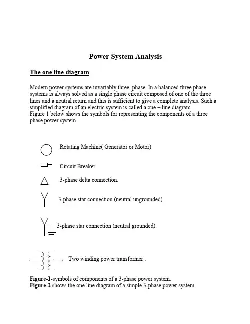
Power System AnalysisThe one line diagramModern power systems are invariably three phase. In a balanced three phase systems is always solved as a single phase circuit composed of one of the three lines and a neutral return and this is sufficient to give a complete analysis. Such a simplified diagram of an electric system is called a one–line diagram. Figure 1 below shows the symbols for representing the components of a three phase power system.Rotating Machine( Generator or Motor).Circuit Breaker.3-phase delta connection.3-phase star connection (neutral ungrounded).3-phase star connection (neutral grounded).Two winding power transformer .Figure-1-symbols of components of a 3-phase power system.Figure-2shows the one line diagram of a simple 3-phase power system.Notes1. Generators neutrals are usually grounded through high resistances and somtimes through inductance coils in order to limit the flow of current to ground during a fault.2. Most transformer neutrals in transmission systems are solidly grounded .Per unit quantityWhen making calculations on a power system network having two or more voltages levels, it is very cumbersome to convert currents to different voltage levels at each point where they flow through a transformer, the change in current being inversely proportional to the transformer turns ratio. In order to simplify these calculations we can use per unit system.In this system a base quantities are assumed for each voltage level and theper unit quantities are calculated as follow:Actual quantityPer unit quantity =ــــــــــــــــــــــــــــــــــــــــ---------------------------(1)Base quantityThe four electrical quantity (voltages, current, power, and impedance) are so related that selection of base values for any two of them determine the base values of the remaining two.Usually base apperant power in megavoltamperes and base voltage in KV are quantities selected to specify the base values.For single phase system or 3-phase on per phase basis , the following relationships hold:Base voltamperesBase current =ــــــــــــــــــــــــــــــــــــــ-----------------------------------(2)Base voltageBase voltageBase impedance =ــــــــــــــــــــــــــ--------------------------------------(3)Base currentActual voltagePer unit voltage =ـــــــــــــــــــــــــــــ-------------------------------------(4)Base voltageActual currentPer unit current =ـــــــــــــــــــــــــــ--------------------------------------(5)Base currentActual impedancePer unit impedance =ـــــــــــــــــــــــــــــــــــــــ---------------------------(6)Base impedanceOrBase KVA 1-phaseBase current =ــــــــــــــــــــــــــــــــــــــــــ--------------------------------(7)Base voltage KV-phBase voltage VphBase impedance =ــــــــــــــــــــــــــــــــــــــ------------------------------(8)Base current Amp2( Base voltage KVph)×1000Base impedance =ـــــــــــــــــــــــــــــــــــــــــــــــــــــــــ------------------(9)Base KVA-ph2(Base voltage KV-ph)Base impedance =ـــــــــــــــــــــــــــــــــــــــــــــــــــــــ------------------(10)Base MVA-phBelow is given annual work summary, do not need friends can download after editor deleted Welcome to visit againXXXX annual work summaryDear every leader, colleagues:Look back end of XXXX, XXXX years of work, have the joy of success in your work, have a collaboration with colleagues, working hard, also have disappointed when encountered difficulties and setbacks. Imperceptible in tense and orderly to be over a year, a year, under the loving care and guidance of the leadership of the company, under the support and help of colleagues, through their own efforts, various aspects have made certain progress, better to complete the job. For better work, sum up experience and lessons, will now work a brief summary.To continuously strengthen learning, improve their comprehensive quality. With good comprehensive quality is the precondition of completes the labor of duty and conditions. A year always put learning in the important position, trying to improve their comprehensive quality. Continuous learning professional skills, learn from surrounding colleagues with rich work experience, equip themselves with knowledge, the expanded aspect of knowledge, efforts to improve their comprehensive quality.The second Do best, strictly perform their responsibilities. Set up the company, to maximize the customer to the satisfaction of the company's products, do a good job in technical services and product promotion to the company. And collected on the properties of the products of the company, in order to make improvement in time, make the products better meet the using demand of the scene.Three to learn to be good at communication, coordinating assistance. On‐site technical service personnel should not only have strong professional technology, should also have good communication ability, a lot of a product due to improper operation to appear problem, but often not customers reflect the quality of no, so this time we need to find out the crux, and customer communication, standardized operation, to avoid customer's mistrust of the products and even the damage of the company's image. Some experiences in the past work, mentality is very important in the work, work to have passion, keep the smile of sunshine, can close the distance between people, easy to communicate with the customer. Do better in the daily work to communicate with customers and achieve customer satisfaction, excellent technical service every time, on behalf of the customer on our products much a understanding and trust.Fourth, we need to continue to learn professional knowledge, do practical grasp skilled operation. Over the past year, through continuous learning and fumble, studied the gas generation, collection and methods, gradually familiar with and master the company introduced the working principle, operation method of gas machine. With the help of the department leaders and colleagues, familiar with and master the launch of the division principle, debugging method of the control system, and to wuhan Chen Guchong garbage power plant of gas machine control system transformation, learn to debug, accumulated some experience. All in all, over the past year, did some work, have also made some achievements, but the results can only represent the past, there are some problems to work, can't meet the higher requirements. In the future work, I must develop the oneself advantage, lack of correct, foster strengths and circumvent weaknesses, for greater achievements. Looking forward to XXXX years of work, I'll be more efforts, constant progress in their jobs, make greater achievements. Every year I have progress, the growth of believe will get greater returns, I will my biggest contribution to the development of the company, believe in yourself do better next year!I wish you all work study progress in the year to come.Actual impedance Per unit impedance=ــــــــــــــــــــــــــــــــــــــــ-----------------------(11)Base impedanceIf we choose base kilovoltamperes and base voltage in kv to mean kilovoltamperes for the total of the 3-phases base voltage for line to line, we find:Base KVA-3-ph Base current =ــــــــــــــــــــــــــــــــــــــــــــ---------------------------(12)3×Base KVA-lineFor 3-phase 2(Base voltage KV)Base impedance =ــــــــــــــــــــــــــــــــــــــــــــــ---------------------(13)Base MVA-3-ph Note:In a 3-phase system, the per unit 3-phase kVA and voltage on the 3-phase basis is equal to the per unit per phase kVA and voltage on the per phase basis.Example1-1: Consider a 3-phase wye –connected 50000 kVA, 120kV system.Express, 40000 kva three phase apperant power and 115 kv line t line voltage in per unit values on (i) 3-phase basis and (ii) per phase basis.Solution;(i) Three phase basis Base kva = 50000 kva Base kv = 120 kv (line to line)P.u kva =8.05000040000=p.u voltage =96.0120115=(ii) per phase basisBase kva =kva 166********1=⨯Base KV =3120=69.28 KV Per unit KVA=166673/40000=0.8Per unit voltage =28.693/115=0.96Change of Base Sometimes it is necessary to convert per-unit quantities from one base to another.The conversion formula for the impedance can be written as follow:()()2⎪⎪⎭⎫ ⎝⎛⨯⎪⎪⎭⎫ ⎝⎛⨯=----new b old b old b new b old pu new pu V V S S Z Z .----------------------------------(14)Example1-2The reactance of a generator Xg is given as 0.25pu based on generator nameplate rating of 18KV , 500MVA.The base for calculations is 20KV And 800MVA.Find Xg on the new base.Solution Xg-new=0.25×22018500100⎪⎭⎫ ⎝⎛⨯⎪⎭⎫ ⎝⎛=0.0405puPer unit impedance of transformer unitThe ohmic values of impedance of a transformer depend on whether they are measured on the high or low tension side of transformer In the per unit system, the per unit impedances of a transformer is the same regardless of whether it is determined from ohmic values referred to the high tension or low tension side of the transformer.Z1=2221N N ohm ----------------(14) . Z1=2221V V ohm ------------------(15 ,The impedance bases on the two sides of the transformer are from equation (13).Z1base =bMVA KV 21-------------------------------(16).Where KV1 is the 1st side base voltage.Z2base =bMVA KV 22-----------------------------(17).Where KV2 is the 2nd side base voltage.To prove that Z1pu=Z2pu22212221222121N N V V MVA KV MVA KV Z Z b b b b b bb b ====.pu b b pu Z Z Z N N Z N N Z Z Z 222222122221111=ΩΩ==ΩΩ=Example 1-3A single phase transformer is rated 110/440, 2.5 kva, leakage reactance measured from low tension side is 0.06Ω. Determine leakage reactance in per unit.Solution From the low tension side Base KV1=110×103-Base MVA= 2.5×10³-Z1b =Ω=⨯⨯--84.4105.2)10110323(base impedance on low tension side).Z1pu=pu Z Z b 0124.084.406.011==ΩFrom the high tension side Base KV2=440 V Base MVA=2.5×10³-Z2=Ω=⨯96.006.011044022Z2b =Ω=⨯⨯--44.77105.2)10440323Z2pu =pu Z Z b 0124.044.7796.022==ΩNote:1. In per unit calculations involving transformer in three phase system, we follow the same principles developed for single phase system and require the base voltage on the two sides of the transformer to have the same ratio as the rated line to line voltage on the two sides of the transformer. The base kva is the same on each side.2. To transfer the ohmic value of impedances from the voltage level on one side of 3 phase transformer to the voltage level on other, the multiplying factor is the square of the ratio of line to line voltages regardless of whether the transformer connection is Example 1-4The three single phase transformers each rated 25 Mva, 38.1/3.81 kv are connected as shown in figure with a balanced load of 0.6Ω-connected resistors. Choose a base of 75 Mva, 66 kv for the high tension side of transformer and specify the base for the low tension side. Determine the per unit resistance of the load on the base for the low tension side. Then determine the load resistance referred to high tension side and the per unit and the per unit value of this resistance on the chosen base.Solution:(1) on the low tension side The base for low tension side is 75 Mva,3.81 kvActual value = 0.6ΩBase value =()Ω=1935.07581.32Per unit value of R L 1.31935.06.0==(2) on the high tension side The base for high tension side is 75 Mva, 66kv Actual value =Ω=⨯18018.3666.022Base value =Ω=08.5875662Per unit value of R L =1.308.58180=Per unit impedance of 3-winding transformersGenerally, large power transformers have three windings. The third winding is known as a tertiary winding which may be used for the following purposes 1.To supply a load at a voltage different from the secondary voltage.2.To provide a low impedance for the flow of certain abnormal currents, such a third harmonic currents.3.To provide for the excitation of a regulating transformer.Note: When one winding is left open, the three winding transformer behaves as two winding transformer and standard short circuit tests can be used to evaluate per unit leakage impedances which are defined as followsZ ps = per unit leakage impedance measured from primary with secondary shorted and tertiary open.Z pt = per unit leakage impedance measured from primary with tertiary shorted and secondary open.Z st= per unit leakage impedance measured from secondary with tertiary shorted and primary pen.Z ps= Z p+ Z s……………(a)Z pt= Z p+ Z t………………(b)Z st= Z s+ Z t………………(c)Where Z p, Z s, and Z t: the impedances of primary, secondary and tertiary. Solving these equations we findZ p= ½ ( Z ps+ Z pt-Z st) ……..(d)Z s= ½ ( Z ps+Zst-Z pt) ……….. (e)Z t= ½ ( Z pt+ Z st–Z ps) ………..(f)These equations can be used to evaluate the per unit series impedances Z p, Z s, and Z t of three winding transformer equivalent circuit from the per unit impedances Z ps, Z pt and Z st which in turn are determined from short circuit tests.Note.The impedances Z p, Z s, and Z t of the three windings are connected in star .Example1-5The 3 phase rating of 3 winding transformer are:Primary:Star-connected, 66KV ,15MVA.Secondary: Star-connected ,13.2KV, 10MVA Tertiary: Delta-connected ,2.3KV,5MVA.Neglecting resistance, the leakage impedances areZ ps = 7% on 15 Mva, 66 kv base Z pt = 9% on 15 Mva, 66kv base Z st = 8% on 10 Mva, 13.2 kv baseFind the per unit impedances of the star connected equivalent circuit for a base of 15 Mva, 66 kv in the primary circuitSolution:With the base 15 Mva, 66 kv S base = 15 Mva for all three terminals is the same and V b1= 66 kv V b2= 13.2 kv V b3= 2.3 kvZ ps = 0.07 (no change)Z pt = 0.09 (no change)Z st = 0.08 ×(15/10)=0.12()pu j j j j Z p 02.012.009.007.021=-+=()pu j j j j Z s 05.009.012.007.021=-+=()puj j j j Z t 07.007.012.009.0=-+=Impedance and Reactance DiagramsLet use take a sample power system network as shown in figure belowThe impedance diagram of this sample network is shown in figure 4In many studies, like faults calculations study, in order to simplify the calculations we can neglect all static loads, all resistances, the magnetizing current of each transformer and the capacitance of transmission line and thus we obtain the reactances diagram as shown in figure.Notes: The impedance and reactance diagrams are sometimes called the positive sequence diagrams.。
电力系统 power system 发电机 generator 励磁 excitation励磁器 excitor 电压 voltage 电流 current升压变压器 step-up transformer 母线 bus 变压器 transformer空载损耗 no-load loss 铁损 iron loss 铜损 copper loss空载电流 no-load current 有功损耗 active loss无功损耗 reactive loss输电系统 power transmission system 高压侧 high side 输电线 transmission line 高压 high voltage 低压 low voltage 中压 middle voltage功角稳定 angle stability 稳定 stability 电压稳定 voltage stability 暂态稳定 transient stability 电厂 power plant 能量输送 power transfer交流 AC 直流 DC 电网 power system落点 drop point 开关站 switch station 调节 regulation高抗 high voltage shunt(逃避)reactor并列的 apposable 裕度 margin故障 fault 三相故障 three phase fault 分接头 tap切机 generator triping 高顶值 high limited value 静态 static (state)动态 dynamic (state) 机端电压控制 AVR 电抗 reactance电阻 resistance 功角 power angle 有功(功率) active power 电容器 Capacitor 电抗器 Reactor 断路器 Breaker电动机 motor 功率因数 power-factor 定子 stator阻抗 impedance 功角 power-angle 电压等级 voltage grade有功负载: active load PLoad 无功负载 reactive load 档位 tap position电阻 resistor 电抗 reactance 电导 conductance电纳 susceptance 上限 upper limit 下限 lower limit正序阻抗 positive sequence impedance 负序阻抗 negative sequenceimpedance零序阻抗 zero sequenceimpedance无功(功率) reactive power 功率因数 power factor 无功电流 reactive current 斜率 slope 额定 rating 变比 ratio参考值 reference value 电压互感器 PT 分接头 tap仿真分析 simulation analysis 下降率 droop rate 传递函数 transfer function 框图 block diagram 受端 receive-side 同步 synchronization保护断路器 circuit breaker 摇摆 swing 阻尼 damping无刷直流电机 Brusless DC motor 刀闸(隔离开关) Isolator 机端 generator terminal变电站 transformer substation给永磁同步电机 Permanent-magnet Synchronism Motor异步电机 Asynchronous Motor三绕组变压器 three-column transformer ThrClnTrans双绕组变压器 double-column transformer DblClmnTrans固定串联电容补偿 fixed series capacitor compensation双回同杆并架 double-circuit lines on the same tower单机无穷大系统 one machine - infinity bus system励磁电流 Magnetizing current 补偿度 degree of compensation电磁场:Electromagnetic fields 失去同步 loss of synchronization装机容量 installed capacity 无功补偿 reactive power compensation故障切除时间 fault clearing time 极限切除时间 critical clearing time强行励磁 reinforced excitation 并联电容器 shunt capacitor<下降特性 droop characteristics 线路补偿器 LDC(line drop compensation)电机学 Electrical Machinery 自动控制理论 Automatic Control Theory电磁场 Electromagnetic Field 微机原理 Principle of Microcomputer电工学 Electrotechnics 电路原理 Principle of circuits电机学 Electrical Machinery电力系统稳态分析 Steady-State Analysis ofPower System电力系统暂态分析 Transient-State Analysis of Power SystemElectrical System's Relay Protection电力系统元件保护原理 Protection Principle of Power System 's Element电力系统内部过电压 Past Voltage within Power system模拟电子技术基础 Basis of Analogue Electronic Technique数字电子技术 Digital Electrical Technique电路原理实验 Lab. of principle of circuits电气工程讲座 Lectures on electrical power production电力电子基础 Basic fundamentals of power electronics高电压工程 High voltage engineering电子专题实践 Topics on experimental project of electronics电气工程概论 Introduction to electrical engineering电子电机集成系统 Electronic machine system 电力传动与控制 Electrical Drive and ControlSystem Relaying Protection主变压器main transformer升压变压器step-up transformer降压变压器step-down transformer工作变压器operating transformer备用变压器standby transformer公用变压器common transformer三相变压器three-phase transformer单相变压器single-phase transformer带负荷调压变压器on-load regulating transformer 变压器铁芯transformer core变压器线圈transformer coil变压器绕组transformer winding变压器油箱transformer oil tank变压器外壳transformer casing变压器风扇transformer fantransformer oil conservator(∽变压器油枕drum变压器额定电压transformer rated voltage变压器额定电流transformer rated currenttransformer voltage regulation 变压器调压范围rage配电设备power distribution equipment SF6断路器SF6 circuit breaker开关switch按钮button隔离开关isolator,disconnector真空开关vacuum switch刀闸开关knife-switch接地刀闸earthing knife-switch电气设备electrical equipment变流器current converter电流互感器current transformer电压互感器voltage transformer电源power source交流电源AC power source直流电源DC power source工作电源operating source备用电源Standby source强电strong current弱电weak current继电器relay信号继电器signal relay电流继电器current relay电压继电器voltage relay跳闸继电器tripping relay合闸继电器closing relay中间继电器intermediate relay时间继电器time relay零序电压继电器zero-sequence voltage relay 差动继电器 differential relay闭锁装置locking device遥控telecontrol遥信telesignalisation遥测telemetering遥调teleregulation断路器breaker,circuit breakermini-oil breaker,oil-mini-mum 少油断路器breaker高频滤波器high-frequency filter组合滤波器combined filter常开触点normally opened contact常闭触点normally closed contact并联电容parallel capacitance保护接地protective earthing熔断器cutout,fusible cutout电缆cable跳闸脉冲tripping pulse合闸脉冲closing pulse一次电压primary voltage二次电压secondary voltage并联电容器parallel capacitorreactive power compensation 无功补偿器device消弧线圈arc-suppressing coil母线Bus,busbar三角接法delta connection星形接法Wye connection原理图schematic diagram一次系统图primary system diagram二次系统图secondary system diagram两相短路two-phase short circuit三相短路three-phase short circuitsingle-phase ground short单相接地短路circuitcalculation of short circuit 短路电流计算current自动重合闸automatic reclosing高频保护high-freqency protection距离保护distance protectiontransverse differential横差保护protectionlongitudinal differential纵差保护protection线路保护line protection过电压保护over-voltage protection母差保护bus differential protection 瓦斯保护Buchholtz protection变压器保护transformer protection电动机保护motor protection远方控制remote control用电量power consumption载波carrier故障fault选择性 selectivity速动性 speed灵敏性 sensitivity可靠性 reliability电磁型继电器 electromagnetic无时限电流速断保护 instantaneously over-current protection跳闸线圈 trip coil工作线圈 operating coil制动线圈 retraint coil主保护 main protection后备保护 back-up protection定时限过电流保护 definite time over-current protection三段式电流保护 the current protection with three stages反时限过电流保护 inverse time over-current protection方向性电流保护 the directional current protection零序电流保护 zero-sequence current protection阻抗 impedance微机保护 Microprocessor Protection。