横河模块接口(配自带安全栅AIO)技术手册
- 格式:pdf
- 大小:697.83 KB
- 文档页数:5

横河接线端子板技术手册AET4D(XAET4D):TC(热电偶)接线端子板MRT(XMRT):RTD(热电阻)接线端子板ARM55C(XARM55C):继电器输出接线端子板(干接点)ARM55W(XARM55W):继电器输出接线端子板(有源)ARM15A(XARM15A):继电器输入接线端子板AED5D(XAED5D):数字量接线端子板AEA4D(XAEA4D):模拟量接线端子板滨州新大新机电科技有限公司常用型号:提供横河兼容接线端子板横河接线端子板技术性能滨州新大新机电科技有限公司一. AEA4D8\16路模拟量输入输出端子板配用DCS 模块: AAI135\AAI835\AAP135 配套电缆: KS1AAI141\ AAI841\\AAI143\AAI543\AAB841 配套电缆: KS1AA V141\AAV142\AAV144 \ AAV542\AAV544 配套电缆: KS1作用形式:电压、电流信号直连输入输出内部连接形式: IDC 座 40P 四组可单一或冗余输入输出现场连接形式: M3.5螺钉带透明盖板端子块四组,端子块可整体拔插绝缘电阻:最小10M Ω(500VDC环境温度和湿度:0~50℃,10~90%RH尺寸: 482mm*83mm重量: 1.8Kg二. AET4D16路TC(热电偶输入端子板配用DCS 模块: AAT145 配套电缆: KS1作用形式:热电偶(mV )信号直连输入内部连接形式: IDC 座 40P 四组可单一或冗余输入输出现场连接形式: M3.5螺钉带透明盖板端子块四组,端子块可整体拔插绝缘电阻:最小10M Ω(500VDC环境温度和湿度:0~50℃,10~90%RH尺寸: 482mm*83mm重量: 1.8Kg三. MRT32路RTD (热电阻)输入端子板配用DCS 模块: AAR145 配套电缆: KS8作用形式:电阻信号直连输入内部连接形式: IDC 座 50P 两组单一输出现场连接形式: M3螺钉带透明盖板端子块四组,端子块可整体拔插绝缘电阻:最小10M Ω(500VDC环境温度和湿度:0~50℃,10~90%RH尺寸: 482mm*83mm重量:1.8Kg四. AED5D32路数字输入输出端子板配用DCS 模块: ADV151\ADV551 配套电缆: AKB331ADV161\ADV561 配套电缆: AKB337作用形式:数字信号直连输入输出内部连接形式: IDC 座 50P 两组可单一或冗余输入输出现场连接形式: M3.5螺钉带透明盖板端子块四组,端子块可整体拔插电源供电: 24VDC 3.2A,带LED 指示和过流、过压、反接保护绝缘电阻:最小10M Ω(500VDC环境温度和湿度:0~50℃,10~90%RH尺寸: 482mm*83mm重量: 1.8Kg五. ARM15A32路继电器隔离输入端子板配用DCS 模块: ADV151 配套电缆: AKB331ADV161 配套电缆: AKB337作用形式:机械式继电器隔离输入内部连接形式: IDC 座 50P 两组可单一或冗余输出输入信号: ON :≤150Ω;OFF :≥200K Ω现场连接形式: M3.5螺钉带透明盖板端子块四组,端子块可整体拔插内部电源供电: 24VDC 0.32A,带LED 指示和过流、过压、反接保护现场电源供电:双路(每16点为一路)24VDC ,每路最大0.3A ,带LED 指示和过流、过压、反接保护回路指示: LED动作指示绝缘电阻:最小10M Ω(500VDC环境温度和湿度:0~50℃,10~90%RH尺寸: 482mm*111mm重量:2.2Kg六. ARM55W32路继电器隔离输出端子板配用DCS 模块: ADV551 配套电缆: AKB331 ADV561 配套电缆: AKB337作用形式:机械式继电器隔离有源输出内部连接形式: IDC 座 50P 两组可单一或冗余输入现场连接形式: M3.5螺钉带透明盖板端子块四组,端子块可整体拔插最大负载: 250V AC :0.6A 每路 30VDC : 0.6A 每路最小负载: 5V , 10 mA内部电源供电: 24VDC 0.65A,带LED 指示和过流、过压、反接保护现场电源供电:双路(每16点为一路),带LED 指示30VDC ,每路最大9.6A 125VDC,每路最大1.6A250VAC ,每路最大9.6A回路指示: LED动作指示和保险熔断报警指示绝缘电阻:最小10M Ω(500VDC环境温度和湿度:0~50℃,10~90%RH尺寸: 482mm*145mm重量: 2.6Kg七. ARM55C32路继电器隔离输出端子板配用DCS 模块: ADV551 配套电缆: AKB331 ADV561 配套电缆: AKB337作用形式:机械式继电器隔离干接点输出(A 为NO ,B 为NC )内部连接形式: IDC 座 50P 两组可单一或冗余输入现场连接形式: M3螺钉带透明盖板端子块四组,端子块可整体拔插电源接线形式: M3.5螺钉端子最大负载: 30VDC ,1.5A 每路最小负载: 5V ,10 mA内部电源供电: 24VDC 0.85A,带LED 指示和过流、过压、反接保护回路指示: LED动作指示绝缘电阻:最小10M Ω(500VDC环境温度和湿度:0~50℃,10~90%RH尺寸: 482mm*127mm重量:2.2Kg专利产品--控制柜配线的全新解决方案控制柜快速接线模块/端子板n 全系列模块化结构:将控制柜内接线附件设计成模块化结构的系列产品,包括模拟及数字信号输入输出、电源分配等,采用统一的标准安装尺寸,元器件透明化设计,指示一目了然,既美观又快捷。
横河模块(O)技术手册横河模块(O)技术手册目录:1.模块概述2.技术规格2.1 尺寸与重量2.2 电气特性2.3 接口2.4 性能参数2.5 环境要求3.安装与配置3.1 硬件安装3.2 软件配置4.使用指南4.1 模块启动与停止4.2 模块功能介绍4.3 模块操作步骤5.故障排除5.1 常见问题解决方法5.2 错误代码与解决方法6.维护与保养6.1 清洁与日常保养6.2 零部件更换7.技术支持7.1 联系信息7.2 常见问题解答7.3 技术咨询1.模块概述本章节介绍横河模块(O)的基本概况,包括产品背景、主要特点以及应用领域等。
2.技术规格本章节详细描述横河模块(O)的技术规格,包括尺寸与重量、电气特性、接口、性能参数和环境要求等。
2.1 尺寸与重量描述模块的尺寸和重量信息,例如长度、宽度、高度和重量等。
2.2 电气特性描述模块的电气特性,例如工作电压、功耗等。
2.3 接口描述模块的各种接口类型和数量,如USB接口、HDMI接口等。
2.4 性能参数描述模块的性能参数,例如处理器速度、内存容量等。
2.5 环境要求描述模块的使用环境要求,如温度范围、湿度等。
3.安装与配置本章节详细描述横河模块(O)的安装和配置步骤,包括硬件安装和软件配置等。
3.1 硬件安装描述模块的硬件安装步骤,包括插拔连接线缆、固定模块等。
3.2 软件配置描述模块的软件配置步骤,包括系统设置、驱动安装等。
4.使用指南本章节提供横河模块(O)的使用指南,包括模块的启动与停止、功能介绍以及操作步骤等。
4.1 模块启动与停止描述模块的启动和停止步骤,包括开机、关机等操作。
4.2 模块功能介绍介绍模块的各种功能和特点,例如图形处理、音频输出等。
4.3 模块操作步骤提供详细的操作步骤,包括模块的设置、调整和使用方法等。
5.故障排除本章节提供故障排除方法,包括常见问题解决方法和错误代码与解决方法等。
5.1 常见问题解决方法列出一些常见问题和对应的解决方法,供用户参考。
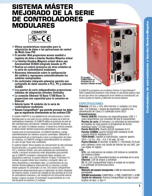
C o n t r o l a d o r e s d e a u t o m a t i z a c i ón e I n t e r f a z H o m b r e -M áq u i n a 1SISTEMA MÁSTER MEJORADO DE LA SERIE DE CONTROLADORES MODULARESl O frece características mejoradas para la adquisición de datos o las aplicaciones de control de Multi-Zone PID l E l servidor Web proporciona acceso mundial a registros de datos e Interfaz Hombre-Máquina virtual l L a Interfaz Hombre-Máquina virtual ofrece una funcionalidad SCADA integrada basada en PC l R ealiza un control jerárquico de otros módulos en la serie de controladores modulares l A lmacena información sobre la configuración del módulo y reprograma automáticamente los módulos reemplazados l U n controlador integrado extensivo permite una cartografía de datos sencilla a PLC, PC y sistemas SCADA l L os puertos de serie independientes proporcionan métodos de integración virtuales ilimitados l L a conexión Ethernet 10 Base-T/100 Base-Tx proporciona una capacidad para la conexión en Ethernet l A dmite hasta 16 módulos de la serie de controladores modulares l R anura Compactflash ® que permite procesar los datos que se registrarán directamente en los archivos CSVEl modelo CSMSTR es una plataforma de comunicaciones y control diseñada para su uso junto con los módulos esclavos de la serie de controladores modulares. El CSMSTR utiliza un protocolo de serie de alta velocidad para comunicarse, mediante una conexión de placa de fondo, con hasta 16 módulos esclavos. A través de la misma conexión, el sitema máster también proporciona alimentación a los módulos.Cuando está en funcionamiento, el CSMSTR identifica y dirige automáticamente los módulos esclavos conectados. Mediante el almacenamiento de la información sobre la configuración de todos los módulos, el CSMSTR configura automáticamente los módulos en caso de que hayan sido sustituidos.El sistema máster ofrece puertos de comunicación de alta velocidad RS232/422/485 y un puerto Ethernet para la conexión a PC, PLC y sistemas SCADA. Una serie exhaustiva de controladores máster y esclavos de protocolo están disponibles para permitir que el CSMSTR comparta e intercambie datos variables con dispositivos externos. El puerto Ethernet 10 Base-T/100 Base-TX también se puede utilizar para conectar y compartir datos con otros dispositivos a velocidades altas. La característica de una Interfaz Hombre-Máquina virtual permite su creación y control desde cualquier PC conectado a la red. Una ranura CompactFlash proporciona almacenamiento para el registrador de datos integrado del sistema máster. El diseño del embalaje de alta densidad de la serie de controladores modulares y del montaje del riel DIN permite ahorrar tiempo y espacio de panel. El controlador encaja fácilmente en el riel DIN del perfil de sombrero (T) estándar.El CSMSTR se programa con el software Crimson 2.0 para Windows ® 2000 o plataformas posteriores. Este software es una interfaz gráfica y fácil de usar que ofrece una configuración de los medios de comunicación, así como la puesta en marcha y calibración de nuevos sistemas.ESPECIFICACIONES Potencia: 24 Vcc ± 10% 400 mA/min (1 módulo) 3,5 Amp máx. (16 módulos + tarjeta de expansión) requiere una alimentación de Clase 2 o calificada como SELV Comunicaciones: Puerto USB/PG: Funciona con especificaciones USB 1.1 (para dispositivos con conexión de tipo B únicamente) P uertos de serie: El formato y la velocidad de transmisión de baudios de cada puerto se programan de forma individual hasta 115.200 baudios Puerto RS232/PG: Puerto RS232 mediante RJ12 Puertos COMMS: puerto RS422/485 mediante RJ45 y puerto RS232 mediante RJ12 TXEN DH485: Habilita la transmisión; colector abierto VOH = 15 Vcc, VOL = 0,5 V @ máx. 25 mA Puerto Ethernet: El enchufe 10 BASE-T / 100 BASE-TX RJ45 e stá cableado como una tarjeta de interfaz de red (NIC, por sus siglas en inglés)LED:S T S: Los indicadores de estado LED indican la condición del sistema máster T X/RX: Los LED transmiten/reciben la actividad de la serie Ethernet: LED de enlace y actividad C F: El LED CompactFlash indica el estado de la tarjeta y la actividad de lectura/escritura Memoria: M emoria del usuario incorporada: 4 MB de memoria flash permanente S DRAM incorporada: CSMSTRSX = 2 MB; CSMSTRGT = 8 MB T arjeta de memoria: Ranura Compactflash de tipo II para tarjetas de tipo I y tipo IIEl modelo CSMSTRSX se muestra en un tamaño inferior al real.CSMSTR2*Notas:1. Criterio A: Funcionamiento normal dentro de ciertos límites.2. Este dispositivo ha sido diseñado para su instalación en un recinto. Para evitar una descarga electrostática de la unidad en entornos con niveles estáticos por encima de 4 kV, se deberán tomar precauciones cuando el dispositivo se monte fuera del recinto. Cuando se trabaja en un recinto (p. ej. realizando ajustes, configuración de puentes, etc.), se deberán tomar precauciones contra las descargas de electricidad estática antes de manipular la unidad.y manual del operador.Ejemplo de pedido: CSMSTRSX, controlador, G3CF002G, tarjeta flash de 2 GB, PSDR0100, alimentación, CSDIO14R, módulo.Reloj en tiempo real: La precisión típica es de menos de un minuto por desfase mensual. La instalación SNTP del Crimson 2.0 permite la sincronización con servidores externos Batería: Pila de botón de litio (incluida). La vida útil típica es de 10 años a 25 °C (77 °F). Cuenta con una variable del sistema de “batería baja” para que el programador pueda escoger acciones específicas si el voltaje de la batería cae por debajo de su voltaje nominal.Condiciones ambientales: R ango de temperatura de funcionamiento: 0 a 50 °C (32 a 122 °F) R ango de temperatura de almacenamiento: -30 a 70 °C (-22 a 158 °F) H umedad relativa de funcionamiento y almacenamiento: máx. 80% humedad relativa, sin condensado, de 0 a 50 °C (32 a 122 °F)Vibración de acuerdo con la norma IEC 68-2-6: 5 a 150 Hz, en dirección X, Y, Z durante 1,5 horas, 2 g’s Choque de acuerdo con la norma IEC 68-2-27: 25 g operativo, 11 mseg. en 3 direcciones Altitud: Hasta 2.000 metros Construcción: La carcasa es de plástico de alto impacto, de color burdeos y acero inoxidable. Categoría de instalación I, grado de contaminación 2Conexiones de alimentación: Bloque terminal con tornillo y abrazadera de cable extraíble Capacidad de calibre de alambre: 24 AWG a 12 AWG Torsión: 4,45 a 5,34 pulg./libras (0,5 a 0,6 N-m)Montaje: Encaja en los rieles de montaje de perfil de sombrero (T) DIN de conformidad con la norma EN50022, -35 x 7,5 y -35 x 15Certificados y conformidad:S eguridad: UL enumerada, archivo #E302106, UL508, CSA 22.2 N.° 14-M05 enumerada por Und. Lab. Inc. para las normas de seguridad de Estados Unidos y Canadá I EC 61010-1, EN 61010-1: Requisitos de seguridad para equipos eléctricos de medición, control y uso en el laboratorio, parte 1Compatibilidad electromagnética: E misiones e inmunidad a la norma EN 61326: Equipos eléctricos de medición, control y para uso en laboratorio I nmunidad a emplazamientos industriales*: Descarga electrostática EN 61000-4-2 Criterio A2; descarga de contacto de 4 kV; descarga de aire de 8 kV; campos electromagnéticos RF EN 61000-4-3 criterio A 10 V/m; transiciones rápidas (rotura) EN 61000-4-4 Criterio A; alimentación de 2 kV; señal de 2 kV; sobrecarga EN 61000-4-5 Criterio A; L-L de 1kV, alimentación L&N-E de 2 kV; interferencias conducidas por RF EN 61000-4-6 Criterio A; 3 V/rms Emisiones: Emisiones EN 55011 de Clase A Peso: 456,4 g (15,1 oz)。

横河接线端子板技术手册常用型号:MRT(XMRT):RTD(热电阻)接线端子板AET4D(XAET4D):TC(热电偶)接线端子板AEA4D(XAEA4D):模拟量接线端子板AED5D(XAED5D):数字量接线端子板ARM15A(XARM15A):继电器输入接线端子板ARM55W(XARM55W):继电器输出接线端子板(有源)ARM55C(XARM55C):继电器输出接线端子板(干接点)滨州新大新机电科技有限公司提供横河兼容接线端子板横河接线端子板技术性能滨州新大新机电科技有限公司一.AEA4D8\16路模拟量输入输出端子板配用DCS模块:AAI135\AAI835\AAP135配套电缆:KS1 AAI141\ AAI841\\AAI143\AAI543\AAB841配套电缆:KS1AA V141\AA V142\AA V144 \ AA V542\AA V544配套电缆:KS1作用形式:电压、电流信号直连输入输出内部连接形式:IDC座40P 四组可单一或冗余输入输出现场连接形式: M3.5螺钉带透明盖板端子块四组,端子块可整体拔插绝缘电阻:最小10MΩ(500VDC)环境温度和湿度:0~50℃,10~90%RH尺寸: 482mm*83mm重量: 1.8Kg二.AET4D16路TC(热电偶)输入端子板配用DCS模块:AAT145 配套电缆:KS1作用形式:热电偶(mV)信号直连输入内部连接形式:IDC座40P 四组可单一或冗余输入输出现场连接形式: M3.5螺钉带透明盖板端子块四组,端子块可整体拔插绝缘电阻:最小10MΩ(500VDC)环境温度和湿度:0~50℃,10~90%RH尺寸: 482mm*83mm重量: 1.8Kg三.MRT32路RTD(热电阻)输入端子板配用DCS模块:AAR145配套电缆:KS8作用形式:电阻信号直连输入内部连接形式:IDC座50P 两组单一输出现场连接形式: M3螺钉带透明盖板端子块四组,端子块可整体拔插绝缘电阻:最小10MΩ(500VDC)环境温度和湿度:0~50℃,10~90%RH尺寸: 482mm*83mm重量: 1.8Kg四.AED5D32路数字输入输出端子板配用DCS模块:ADV151\ADV551配套电缆:AKB331ADV161\ADV561配套电缆:AKB337作用形式:数字信号直连输入输出内部连接形式:IDC座50P 两组可单一或冗余输入输出现场连接形式: M3.5螺钉带透明盖板端子块四组,端子块可整体拔插电源供电: 24VDC 3.2A,带LED指示和过流、过压、反接保护绝缘电阻:最小10MΩ(500VDC)环境温度和湿度:0~50℃,10~90%RH尺寸: 482mm*83mm重量: 1.8Kg32路继电器隔离输入端子板配用DCS模块:ADV151配套电缆:AKB331ADV161配套电缆:AKB337作用形式:机械式继电器隔离输入内部连接形式:IDC座50P 两组可单一或冗余输出输入信号:ON:≤150Ω;OFF:≥200KΩ现场连接形式: M3.5螺钉带透明盖板端子块四组,端子块可整体拔插内部电源供电: 24VDC 0.32A,带LED指示和过流、过压、反接保护现场电源供电:双路(每16点为一路)24VDC,每路最大0.3A,带LED指示和过流、过压、反接保护回路指示: LED动作指示绝缘电阻:最小10MΩ(500VDC)环境温度和湿度:0~50℃,10~90%RH尺寸: 482mm*111mm重量: 2.2Kg32路继电器隔离输出端子板配用DCS模块:ADV551配套电缆:AKB331ADV561 配套电缆:AKB337作用形式:机械式继电器隔离有源输出内部连接形式:IDC座50P 两组可单一或冗余输入现场连接形式: M3.5螺钉带透明盖板端子块四组,端子块可整体拔插最大负载:250V AC:0.6A每路30VDC:0.6A每路最小负载:5V, 10 mA内部电源供电: 24VDC 0.65A,带LED指示和过流、过压、反接保护现场电源供电:双路(每16点为一路),带LED指示30VDC,每路最大9.6A 125VDC,每路最大1.6A250VAC,每路最大9.6A回路指示: LED动作指示和保险熔断报警指示绝缘电阻:最小10MΩ(500VDC)环境温度和湿度:0~50℃,10~90%RH尺寸: 482mm*145mm重量: 2.6Kg32路继电器隔离输出端子板配用DCS模块:ADV551配套电缆:AKB331ADV561 配套电缆:AKB337作用形式:机械式继电器隔离干接点输出(A为NO,B为NC)内部连接形式:IDC座50P 两组可单一或冗余输入现场连接形式: M3螺钉带透明盖板端子块四组,端子块可整体拔插电源接线形式: M3.5螺钉端子最大负载:30VDC,1.5A每路最小负载:5V,10 mA内部电源供电: 24VDC 0.85A,带LED指示和过流、过压、反接保护回路指示: LED动作指示绝缘电阻:最小10MΩ(500VDC)环境温度和湿度:0~50℃,10~90%RH尺寸: 482mm*127mm重量: 2.2Kg专利产品--控制柜配线的全新解决方案控制柜快速接线模块/端子板n全系列模块化结构:将控制柜内接线附件设计成模块化结构的系列产品,包括模拟及数字信号输入输出、电源分配等,采用统一的标准安装尺寸,元器件透明化设计,指示一目了然,既美观又快捷。
横河模块(DIO)技术手册横河模块(DIO)技术手册1. 简介横河模块(DIO - Digital Input/Output)是一种用于控制和监测数字信号的设备,常用于工业自动化系统中。
本技术手册提供了关于横河模块的详细信息和使用说明。
2. 模块类型和规格2.1 模块类型横河模块(DIO)包括以下几种类型:输入模块、输出模块和输入/输出模块。
2.2 模块规格每种类型的横河模块(DIO)具有不同的规格和功能。
以下是常见的规格参数:- 输入模块:支持多个数字输入通道,每通道可以读取高或低电平信号。
- 输出模块:支持多个数字输出通道,可以发送高或低电平信号。
- 输入/输出模块:既可以读取数字输入信号,也可以发送数字输出信号。
3. 安装和连接3.1 安装将横河模块(DIO)安装在合适的位置,确保模块与其他设备之间有足够的空间。
3.2 连接将模块与其他设备连接,确保连接稳固可靠。
根据需要使用合适的电缆和接头。
4. 配置和编程4.1 配置在使用横河模块(DIO)之前,需要对其进行配置。
配置方式包括硬件设置和软件设置。
具体的配置方法请参考相应的用户手册。
4.2 编程横河模块(DIO)可以通过编程控制和监测数字信号。
根据所使用的编程语言,可以使用相应的库或API进行编程。
详细的编程说明和示例请参考相关的开发文档。
5. 故障排除在使用横河模块(DIO)时,可能会遇到各种故障。
以下是一些常见的故障及其排除方法:- 无法读取输入信号:检查输入信号的连接是否正确,确保输入通道有效。
- 无法发送输出信号:检查输出信号的连接是否正确,确保输出通道有效。
6. 附件本文档涉及的附件包括:- 横河模块(DIO)用户手册:提供了更多详细的使用说明和配置信息。
- 横河模块(DIO)开发文档:提供了编程接口和示例代码。
7. 法律名词及注释本文涉及的法律名词及其注释如下:- DIO: Digital Input/Output,数字输入/输出。
U C omplete Sensorto RS232C or RS485 Interface U I nput Modules forThermocouples, RTDs,Voltages, Currents, Pulse and Frequency, and Bridge Inputs U I solated Inputs U R S485 Format Permits Remote Communications up to 4000'U D 2000 Series Provide Linearization ofNon-Standard Sensors U C onnect Up To 32 Modules On One Cable, Up to 124 Using a Repeater U A larm Outputs Standard U C ontinuous Self Calibration, No Adjustment RequirementsThe D1000 and D2000 Series digital transmitters are a complete family of easy to use interface modules for personal computers and other processor based equipment with standard serial I/O ports. The modules convert analog input signals to engineering units and transmit, in ASCII format, to any host computer with a standard RS-232C or RS-485 port. This modular design enables anyone familiar with a personal computer to construct a flexible and cost effective data acquisition system. These modules can measuretemperature, pressure, flow, voltages, currents and various types of digital signals. The D1000 series provide direct interface to a wide variety of sensors and perform all signalconditioning, scaling, linearization and conversion to engineering units. Each module also provides digital I/O lines for controlling devices through solid state relays or TTL signals. These digital I/O lines along with integral limit setting capability provide alarm and control outputs. With the exception of the D1400 RTD and D1500 bridge modules, every D1000 module contains an on-board event counter. The event counter will count up to ten million transitions on the digital input line.All user selectable options (address, baud rate, alarms, etc.) are done through the communications port and stored in nonvolatile memory thereby eliminating switches or external adjustments of any kind.The flexibility of this system allows users to mix and match the modules to fit their exact requirements. As many as 124 modules can be connected on one 4 wire cable.They can be placed remote from the host computer and from each other.The D2000 series of user-programmable data acquisition and control modules allow direct interface of non-linear analog sensors to computers with serial I/O ports.D1000 and D2000 SeriesOMEGABUS ®Digital TransmittersA/INA/OUTDI/OSERIAL I/OD1000 and D2000 Modules are Easily Arranged in Multidrop Fashion for Multiple InputsUse of these modules enables downloading up to 23 breakpoints through the communications port. With these breakpoints the user can program a module to virtually any transfer function.The ability to provide an arbitrary user programmable nonlinear transfer function is the most powerful feature of the D2000 series. Use this feature to linearize non-standard sensors or to provide outputs in engineering units, which arenonlinear to the input. The D2000series can be programmed toapproximate square law, root, log,high-order polynominal or any other non-linear function.The D2000 may also be empirically field-programmed when the exact transfer function is unknown.If transmitting long distances is required, selection of theRS-485 communications format isencouraged. This permits remote operation of up to four thousand feet from the host computer. For computers which do not include a RS-485 port, OMEGA offers the A1000 RS-232C signal converter. The modules are also capable of operating in a multidrop fashion supporting up to 32 units one one cable set. The A1000 may alsobe used as a repeater to allow as many as 124 modules to be joinedtogether. A utility software package (for IBM PC or compatibles) is also available. This software eliminates the need for programming skills to easily communicate with the modules. This software package is available upon request at no charge. Request model D1000-SW, for D1000, D2000, D3000 and D4000 models. (One per order).All modules are supplied withscrew terminal plug connectors and captive mounting hardware. Their encapsulated design allows for mounting in virtually any location including explosion proof housings and DIN rails.Common SpecificationsANALOGU Single channel analog input U A nalog Input isolation to 500 VRMS U 15-bit measurement resolution U 2 samples/sec throughout U Autozero & autocalibration DIGITALU 8-bit CMOS microcomputer COMMUNICATIONS U RS-232C, RS-485U U p to 124 multidrop modules per communications port U A SCII Format command/ response protocolU Can be used with ‘dumb’ terminal U Parity options: odd, even, none U A ll communications setups stored in memory U C hecksum can be added to any command or responseU User selectable channel address U S electable baud rates: 300, 600, 1200, 2400, 4800, 9600, 19.2 K, 38.4 KPower Requirements: 10 to 30 Vdc, 0.75 W maxCase: ABS with captive mounting hardwareConnectors: Screw terminal plug (supplied)TEMPERATURE RANGE Operating: -25 to 70°C Storage: -25 to 85°CRelative Humidity: 0 to 95% noncondensingSpecificationsfor Specific ModulesD1100/D2100 VOLTAGE INPUT MODULESVoltage Ranges: ±10 mV, ±100 mV, ±1V, ±5 V, ±10 Vdc, ±100 Vdc Resolution: 0.01% of FS (4 digits)Accuracy: ±0.02% of FS maxZero Drift: ±1 count max (auto zero)Span Tempco: ±50ppm/°C max Input Burnout Protection: 250 Vac Input Impedance: 1 M Ω min (> ±5V input), 100M Ω min (< ± 1V input)1 Digital Input/Event Counter, 2 Digital OutputsD1200/D2200 Current Input ModulesCurrent Ranges: ±1 mA, ±10 mA ±100 mA, ±1A, 4 to 20 mA dcResolution: 0.01% of FS (4 digits), 0.04% of FS (4-20 mA)Accuracy: ±0.02% of FS, 0.04% of FS (4-20 mA)Zero Drift: ±1 count max. (autozero)Span Tempco: ±80 ppm/°C max Voltage Drop: ±0.1V max1 Digital Input/Event Counter,2 Digital OutputsD1300 THERMOCOUPLE INPUT MODULES U O pen thermocouple indication U I nput burnout protection to 250 Vac U U ser selectable °C or °F U O verrange indication U A utomatic cold junctioncompensation and linearization Thermocouple Types: J, K, T, E, R, S, B, C RANGES:J = -200 to 760°C; K = -150 to 1250°C; T = -200 to 400°C; E = -100 to 1000°C; B = 0 to 1820°C; S = 0 to 1750°C; R = 0 to 1750°C; C = 0 to 2315°C Resolution: ±1.0°Overall Accuracy From 0 to +40°C Ambient: ±1.0°C max (J, K, T, E), ±2.5°C max (R, S, B, C)Input Impedance: 100 M Ω min.Lead Resistance Effect: <20µ V per 350Ω2 Digital Inputs, Event Counter,3 Digital OutputsD1400 RTD INPUT MODULE U I nput protection to 120 Vac U A utomatic linearization and lead compensation U U ser selectable °C or °FRTD Types: a = .00385, .00392, 100 Ω @ 0°CRanges: .00385 = -200 to 850°C; .00392 = -200 to 600°C Resolution: 0.1°Accuracy: ±0.3°CInput Connections: 2, 3,or 4 wire Excitation Current: 0.25 mA Lead resistance effect: 3 wire–2.5°C per Ω of unbalance; 4 wire – negligibleMax Lead Resistance: 50ΩShown in Multidrop FashionD1500 Bridge Input Modules are ideally suited for most load cells. See OMEGA’s Pressure, Strain and Force Handbook for a complete line of load cells.Input ModulesFor Virtually Any Process Monitoring ApplicationDI/OD1331D1332 TD 1711 D1712 15 Digital in/outVoltage, current and bridge input modules are readily interfaced to most pressure transducers.See OMEGA’s Pressure, Strain and Force Handbook for a complete line of pressure transducers.D1000 Series digital transmitters are also available with Modbus RTU protocol.To order transmitters Modbus RTU protocol, add suffix “M” at the end of the model number, no additional charge.Ordering Example: D1311 type J thermocouple input RS-232C output digital transmitter and OCW-1, OMEGACARE SM extends standard 1-year warranty to a total of 2 years.1 Digital OutputD1450 THERMISTOR INPUT Range: 0 to 100°CThermistor Type: 2252ΩAccuracy: ±0.2°C Resolution: 0.01°C/°F Input Protection: 30 Vdc1 Digital Input/Event Counter,2 Digital OutputsD1500/2500 BRIDGE INPUT MODULERange: ±30, ±100 mV, 1 to 6 VdcAccuracy: ±0.05% of FS maxResolution: 10 µv (mV spans),0.02% FS (V span)Common Mode Rejection: 100 dB at 50/60 HzInput Protection: 30 VdcExcitation Voltage: 10 V, 5 Vdc 1 Digital Output D1600/D2600 TIMER AND FREQUENCY INPUT MODULES The D1600 module has two modes:frequency input with output data in hertz, or timer input with output data in secondsInput impedance: 1 M ΩSwitching Level: Selectable 0V, 2.5V Hysteresis: adjustable 10 mV to 1.0V Input Protection: 250 Vac1 Digital Input/Event CountersFREQUENCY INPUTRange: 1 Hz to 20 kHzAccuracy: ±0.01% of reading, ±0.01 Hz Resolution: 0.005% of reading, 0.01 HzResolution: 0.01% (4 digits) Tempco: ±20 ppm/°C TIMER INPUT Range: 100 µs to 30 s Resolution: 0.005% of reading +10 µs Accuracy: ±0.01% of reading ±10 µs EVENT COUNTER Input Bandwidth: 60 Hz, (optional 20 KHz max)Up to 10 million positive transitions D1700 DIGITAL INPUTS/OUTPUTS MODULED1711, D1712: 15 digital input/output bits, user can define any bit as an input or an outputInput Voltage Levels: 0 to 30V without damageInput Switching Levels: High, 3.5V min., Low, 1.0V maxOutputs: Open collector to 30V, 100 mA max loadD1701, D1702: 7 DIGITAL INPUTS AND 8 DIGITAL OUTPUTS Input Voltage Levels: ±30V without damage Input Switching Levels: high,3.5V min, low, 1.0V max Outputs: Open collector to 30V, 30 mA max loadVsat: 0.2V max @ 30 mAInternal pull up resistors for direct switch inputInputs/Outputs are read/set in parallelD2221D2222 1 mAARTWORK/PRODUCT ART/ DAS/D-D100 DIAD2131D2132 5VShown in Multidrop Fashion OMEGABUS® Digital TransmittersD1000 and D2000 ModelsOMEGACARE SM extendedwarranty program is available formodels shown on this page. Askyour sales representative for fulldetails when placing an order.OMEGACARE SM covers parts,labor and equivalent loaners.。
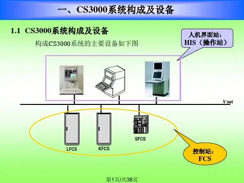
横河DCS操作工手册横河西仪有限公司系统部 - 1 - 神马特品工业丝CS3000系统运行操作说明第1 页共25页神马特品工业丝CS3000 系统应用软件操作说明书横河西仪有限公司系统部出版发行2006/05/01横河西仪有限公司系统部 - 2 - 神马特品工业丝CS3000系统运行操作说明第2 页共25页总目录一、前言-------------------------------------------------------------------------- -3-二、流程图画面总目录 ---------------------------------------------------------- -4-三、软件操作说明 --------------------------------------------------------------- -14-1、画面操作 ----------------------------------------------------------------- -14-1-1 总貌画面 ---------------------------------------------------------- -14-1-2 流程图画面 ------------------------------------------------------- -14-1-3 控制分组画面 ---------------------------------------------------- -15-2、仪表操作 ----------------------------------------------------------------- -16-2-1 开关仪表面板 ---------------------------------------------------- -16-2-2 调节仪表面板 ---------------------------------------------------- -173、报表操作 ----------------------------------------------------------------- -17-四、系统操作说明 --------------------------------------------------------------- -18-1、人机接口 ---------------------------------------------------------------- -18-1-1 人机接口功能 ----------------------------------------------------- -18-1-2 窗口类型 ----------------------------------------------------------- -181-3 窗口操作 ----------------------------------------------------------- -19-1-4 典型的操作监视窗口 -------------------------------------------- -192、系统基本维护 ---------------------------------------------------------- -30-2-1 系统维护窗口 ------------------------------------------------------ -30-2-2 过程报告书 --------------------------------------------------------- -332-3 历史报告书 --------------------------------------------------------- -33-3、操作员键盘---------------------------------------------------------------- -34-五、后记------------------------------------------------------------------------------ -35-横河西仪有限公司系统部 - 3 - 神马特品工业丝CS3000系统运行操作说明第3 页共25页前言神马特品工业丝计算机分散控制系统采用横河西仪有限公司提供的CENTUM-CS3000 控制系统。
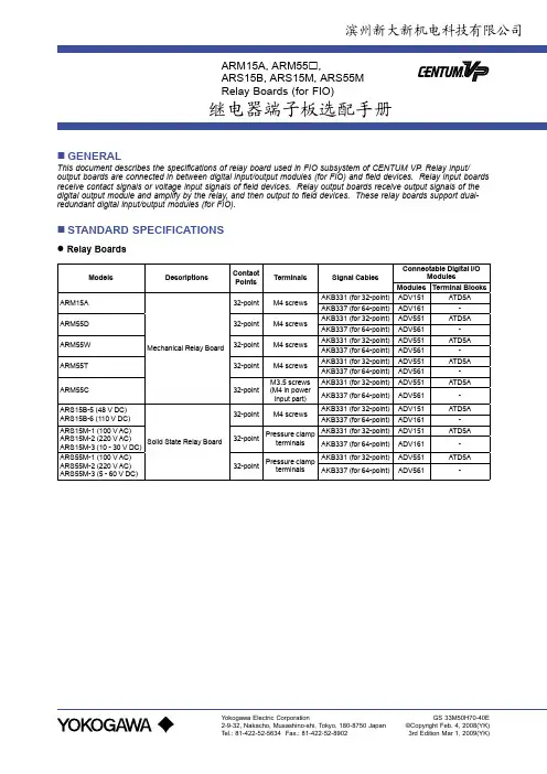
General
Specifications
<<Contents>> <<Index>>
Terminal Block
(for I/O Modules with Built-In Barrier)
GS 33M50H40-40E
⏹ GENERAL
This GS covers the hardware specifications of the Terminal Block that can be used for Modules with Built-In Barrier (FIO) of CENTUM VP .
When installing these apparatuses with intrinsically safe circuit, “Explosion Protection” (TI 33Q01J30-01E) and “Explosion Protection of FIO Products” (IM 33Y06K01-90E) for CENELEC Approval should be referenced together with this GS.
These terminal blocks are compliant with ISA S71.04 class G3. The temperature range of the module is -20 to 70 °C.
⏹ STANDARD SPECIFICATIONS
Variation of Connection
Terminal blocks are used to connect I/O modules with built-in barriers to field devices. The pressure clamp terminal
block is available for I/O modules with Built-In Barrier.
Terminal block
滨州新大新机电科技有限公司
Terminal Block
Model Name Application
Connecting Point Connecting Module Name Weight Specifications
ATSA3S Analog (Single)
8-Point ASI133 0.2 kg Without surge absorber
ATSA3D Analog (Dual-Redundant)
8-Point ASI133 0.3 kg ATST4S Analog Thermocouple/mV (Single)
16-Point AST143 0.2 kg ATST4D Analog Thermocouple/mV (Dual-Redundant) 16-Point AST143 0.3 kg ATSR3S Analog RTD/POT (Single)
8-Point ASR133 0.2 kg ATSR3D Analog RTD/POT (Dual-Redundant) 8-Point ASR133 0.3 kg ATSS3S Analog output
8-Point ASI533 0.2 kg ATSS3D Analog output (Dual-Redundant) 8-Point ASI533 0.3 kg ATSB4S Digital input (Single)
16-Point ASD143 0.2 kg ATSB4D Digital input (Dual-Redundant) 16-Point ASD143 0.3 kg ATSD3S Digital output (Single)
8-Point ASD533 0.2 kg ATSD3D
Digital output (Dual-Redundant)
8-Point
ASD533
0.3 kg
EXTERNAL DIMENSIONS
ATSA3S, ATSS3S, ATST4S, ATSR3S, ATSB4S, ATSD3S
F02E.ai
Unit: mm
ATSA3D, ATSS3D, ATST4D, ATSR3D, ATSB4D, ATSD3D
F05E.ai
Unit: mm
⏹ MODELS AND SUFFIX CODES
Pressure Clamp Terminal Block
Description
Models ATSA3S Pressure Clamp T erminal Block for Analog Input (8-channel) ATSS3S Pressure Clamp T erminal Block for Analog Output (8-channel) ATST4S Pressure Clamp T erminal Block for TC/mV (16-channel) ATSR3S Pressure Clamp T erminal Block for RTD/POT (8-channel) ATSB4S Pressure Clamp T erminal Block for Digital Input (16-channel) ATSD3S Pressure Clamp T erminal Block for Digital Output (8-channel)
Suffix Code -0 Always -0
Dual-Redundant Pressure Clamp Terminal Block
Description
Models ATSA3D Dual-Redundant Pressure Clamp T erminal Block for Analog Input (8-channel) ATSS3D Dual-Redundant Pressure Clamp T erminal Block for Analog Output (8-channel) ATST4D Dual-Redundant Pressure Clamp T erminal Block for TC/mV (16-channel) ATSR3D Dual-Redundant Pressure Clamp T erminal Block for RTD/POT (8-channel) ATSB4D Dual-Redundant Pressure Clamp T erminal Block for Digital Input (16-channel) ATSD3D Dual-Redundant Pressure Clamp T erminal Block for Digital Output (8-channel)
Suffix Code -0 Always -0
⏹ ORDERING INFORMATION
Specify the model and suffix codes.
⏹ TRADEMARK
• CENTUM is a registered trademark of Yokogawa Electric Corporation.
• Other company names and product names in this document are registered trademarks or trademarks of their respective holders.
滨州新大新专利产品
快速接线模块\端子板控制柜装配的全新概念
多
快
好
省
n全系列模块化结构:将控制柜内接线附件设计成模块化结构的系列产品,包括模拟及数字信号输入输出、电源分配等,采用统一标准的安装尺寸,元器件透明化设计,指示一目了然,既美观又快捷。
n简化盘内布线:采用板上跳线的型式解决了设备接线方式的差异化和复杂化问题。
信号传输和供电(直流)巧妙有机的融合在一起,接驳不同类型的仪表和信号只需在板上改变跳线即可,一个短路块就能省去一根线,减少了线路节点,降低了复杂线路对图纸的依赖性,彻底简化了盘内布线过程。
n省略端子排:配备了新型的拔插式或弹簧式快速接线端子,接线迅速快捷并有足够强度。
可直接接驳1~2.5mm2导线,不必再专门配备接线端子排。
内部接线端可采用端子或D-SUB接口,与PLC或DCS连接可采用DB25针接口从板上集中引线。
n不拆线停表,免配电开关,避免误操作:各输入输出回路均配备了拔插方便的保险以提供全方位的安全保障,用户不必再为外部设备单独配备配电开关和保险端子。
特别解决了DCS及PLC系统外围仪表停表的问题,检修、拆除外部设备只要拔下保险而不必拆线,既快捷高效又安全可靠防止错接。
电源回路采用过压、过流、反接保护措施,确保设备安全。
n免万用表,免拆线测电流:电源回路和数字输入输出回路均配备全方位的LED信号指示及保险熔断报警,巧妙特有的不拆线测量信号电流技术,测量信号电流只要将电流表表笔插入测试孔即可,整个测量过程设备不断电、不影响正常测控过程。