第五讲 直流驱动建模与分析
- 格式:ppt
- 大小:1.30 MB
- 文档页数:93
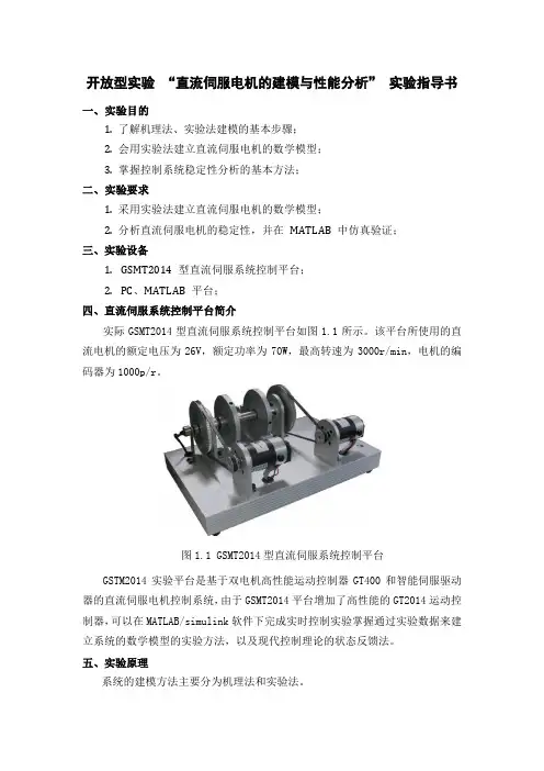
开放型实验“直流伺服电机的建模与性能分析”实验指导书一、实验目的1. 了解机理法、实验法建模的基本步骤;2. 会用实验法建立直流伺服电机的数学模型;3. 掌握控制系统稳定性分析的基本方法;二、实验要求1. 采用实验法建立直流伺服电机的数学模型;2. 分析直流伺服电机的稳定性,并在MATLAB 中仿真验证;三、实验设备1. GSMT2014 型直流伺服系统控制平台;2. PC、MATLAB 平台;四、直流伺服系统控制平台简介实际GSMT2014型直流伺服系统控制平台如图1.1所示。
该平台所使用的直流电机的额定电压为26V,额定功率为70W,最高转速为3000r/min,电机的编码器为1000p/r。
图1.1 GSMT2014型直流伺服系统控制平台GSTM2014实验平台是基于双电机高性能运动控制器GT400和智能伺服驱动器的直流伺服电机控制系统,由于GSMT2014平台增加了高性能的GT2014运动控制器,可以在MATLAB/simulink软件下完成实时控制实验掌握通过实验数据来建立系统的数学模型的实验方法,以及现代控制理论的状态反馈法。
五、实验原理系统的建模方法主要分为机理法和实验法。
1.机理法建立直流伺服电机数学模型采用机理法建立系统模型,需要深入理解系统内部的各个部分之间的关系,可以通过简化模型原理图得出,直流伺服电机的简化模型原理图如图1.2所示。
图1.2 直流电机的等效电路a U ——定义为电枢电压(伏特)b U ——定义为反电动势(伏特)a I ——定义为电枢电流(安倍)a R ——定义为电枢电阻(欧姆)a L ——定义为电枢电感(亨利)m T ——定义为电机产生的转矩(牛顿·米)c T ——定义为系统的干扰力矩(牛顿·米)m J ——定义为负载的等效转动惯量(千克·米²)结合直流伺服机的等效电路模型可以得出:(1)电枢电压方程: dt t di La t i a a )()(R t U -t U a b a +=)()((1-1) (2)电动机的转矩:a m kI T =(1-2) 式中:k ——电动机的转矩常数(3)电动机的反电动势:n b w K =b U(1-3) 式中:b K ——反电动势常数(4)转矩平衡方程: c m T dt d J +=22m T θ(1-4)当改变电动机的电枢电压时,根据(1-1)、(1-2)、(1-3)、(1-4)式可以得出直流电动机的动态微分方程为: c f a c e T K U K t n dtt dn dt t n d -=++)()()(m 22m τττ (1-5) 其中:ετ——电磁时间常数; f K ——机械特性斜率;m τ——机械时间常数; c K ——转速常数;)(t n ——电机转速。
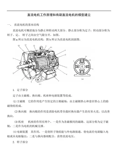
直流电机工作原理和有刷直流电机的模型建立一、直流电机的基本结构直流电机可概括地分为静止和转动两大部分。
静止部分称为定子;转动部分称为转子。
定、转子之间由空气隙分开,如图。
图a所示为直流电机结构,图b所示为直流电机剖面图。
1. 定子部分定子由主磁极、换向极、机座和电刷装置等组成。
(1)主磁极它的作用是产生恒定的主极磁场,由主磁极铁心和套在铁心上的励磁绕组组成。
(2)换向极换向极的作用是消除电机带负载时换向器产生的有害火花,以改善换向。
(3)机座机座的作用有两个,一是作为各磁极间的磁路,这部分称为定子磁轭;二是作为电机的机械支撑。
(4)电刷装置其作用,一是使转子绕组能与外电路接通,使电流经电刷输入电枢或从电枢输出;二是与换向器相配合,获得直流电压。
2. 转子部分转子是直流电机的重要部件。
由于感应电势和电磁转矩都在转子绕组中产生.是机械能与电能相互转换的枢纽,因此称作电枢。
电枢主要包括电枢铁心、电枢绕组、换向器等。
另外转子上还有风扇、转轴和绕组支架等部件。
(1)电枢:铁心电枢铁心的作用有两个,一是作为磁路的一部分,二是将电枢绕组安放在铁心的槽内。
(2)电枢绕组:电枢绕组的作用是产生感应电势和通过电流,使电机实现机电.能量转换它由许多形状完全相同的线圈按一定规律连接而成。
每一线圈的两个边分别嵌在包枢铁心的槽里,线圈的这两个边也称为有效线圈边。
(3)换向器:换向器又称整流子,在直流电动机中,是将电刷上的直流电流转换为绕组内的交变电流,以保证同一磁极下电枢导体的电流方向不变,使产生的电磁转矩恒定;在直流发电机中,是将绕组中的交流感应电势转换为电刷上的直流电势,所以换向器是直流电机中的关键部件。
换向器由许多鸽尾形铜片(换向片)组成。
换向片之间用云母片绝缘,电枢绕组每一个线圈的两端分别接在两个换向片上,换向器的结构如图1-2所示。
直流电机运行时在电刷与换向器之间往往会产生火花。
微弱的火花对电机运行并无危害,若换向不良,火花超过一定程度,电刷和换向器就会烧坏,使电机不能继续运行。
动态系统建模仿真实验报告姓名:学号:联系方式:(Tel)(Email)2010年11月11日目录1直流电动机建模及仿真实验 (1)1.1实验目的 .............................................................................................................. 1 1.2实验设备 .............................................................................................................. 1 1.3实验原理及实验要求 .......................................................................................... 1 1.3.1实验原理 ....................................................................................................... 1 1.3.2实验要求 ....................................................................................................... 2 1.4实验内容及步骤 .................................................................................................. 3 1.4.1求电动机的传递函数模型和频率特性 ....................................................... 3 1.4.2设计Simulink 框图求电机的调速特性 ....................................................... 5 1.4.3设计Simulink 框图求电机的机械特性 ....................................................... 7 1.4.4求电机转速的阶跃响应和机电时间常数 ................................................... 8 1.5实验结果分析 . (10)2考虑结构刚度时的直流电动机-负载建模及仿真实验 (11)2.1实验目的 ............................................................................................................ 11 2.2实验设备 ............................................................................................................ 11 2.3实验原理及实验要求 ........................................................................................ 11 2.3.1实验原理 ..................................................................................................... 11 2.3.2实验要求 ..................................................................................................... 13 2.4实验内容及步骤 ................................................................................................ 13 2.4.1求从a u 到m θ的传递函数模型和频率特性 ................................................ 13 2.4.2求从m θ到L θ的传递函数模型、频率特性和根轨迹 ............................... 15 2.4.3求不同刚度系数对应的从a u 到L θ的电机-负载模型的频率特性 ........... 17 2.5实验结果分析 . (18)1直流电动机建模及仿真实验1.1实验目的(1)了解直流电动机的工作原理; (2)了解直流电动机的技术指标; (3)掌握直流电动机的建模及分析方法;(4)学习计算直流电动机频率特性及时域响应的方法。
直流伺服控制系统的数学模型
直流伺服控制系统的数学模型可以描述为一个单输入单输出的控制系统,其中输出信号为电机角位置或角速度,输入信号为电机的电压。
系统的基本元素为直流电机,功率放大器,编码器和反馈环路。
系统的传递函数可以表示为:
G(s) = \frac{K}{s(JLs + bJ + K^2)}
其中,K为电机增益系数,J为电机惯性矩,L为电机电感,b为电机摩擦系数,K为电机电动势常数。
将输入信号表示为U(s),输出信号表示为\theta(s),则系统的闭环传递函数可以表示为:
\frac{\theta(s)}{U(s)} = \frac{K}{s^2(JLs + bJ + K^2) + K^2}
为了使系统稳定,需要设计合适的控制器增益。
常用的控制方法包括PID控制、模型预测控制等。
总之,直流伺服控制系统的数学模型可以用传递函数表示,通过设计合适的控制器增益实现稳定的控制。
开环直流调速系统的动态建模与仿真学院:电气与控制工程学院班级:学号:姓名:设计题目:开环直流调速系统的动态建模与仿真设计目的:1.掌握开环直流调速系统的建模方法2.熟悉MATLAB/Simulink的使用方法MATLAB的概述:MATLAB是矩阵实验室(Matrix Laboratory)的简称,是美国MathWorks公司出品的商业数学软件,用于算法开发、数据可视化、数据分析以及数值计算的高级技术计算语言和交互式环境,主要包括MATLAB和Simulink两大部分。
MATLAB是由美国mathworks公司发布的主要面对科学计算、可视化以及交互式程序设计的高科技计算环境。
它将数值分析、矩阵计算、科学数据可视化以及非线性动态系统的建模和仿真等诸多强大功能集成在一个易于使用的视窗环境中,为科学研究、工程设计以及必须进行有效数值计算的众多科学领域提供了一种全面的解决方案,并在很大程度上摆脱了传统非交互式程序设计语言(如C、Fortran)的编辑模式,代表了当今国际科学计算软件的先进水平。
MATLAB是目前国际上最流行,应用最广泛的科学与工程计算软件,它由MATLAB语言,MATLAB工作环境,MATLAB图像处理系统,MATLAB数据函数库,MATLAB应用程序接口五大部分组成的集数值计算,图形处理,程序开发为一体的功能强大的系统.它应用于自动控制,数学计算,信号分析,计算机技术,图像信号处理,财务分析,航天工业,汽车工业,生物医学工程,语音处理和雷达工程等各行业,也是国内高校和研究部门进行许多科学研究的重要工具。
MATLAB的基本数据单位是矩阵,它的指令表达式与数学,工程中常用的形式十分相似,故用MATLAB来解算问题要比用C,FORTRAN等语言完相同的事情简捷得多。
MATLAB是以矩阵运算为基础的交互式程序语言,能够满足科学、工程计算和绘图的需求。
与其它计算机语言相比,其特点是简洁和智能化,适应科技专业人员的思维方式和书写习惯,使得编程和调试效率大大提高。
机电传动控制系统的动力学建模与分析1. 引言机电传动控制系统是一种应用广泛的系统,其由机械传动和电气控制组成。
在设计和分析机电传动控制系统时,了解其动力学行为是至关重要的。
本文将介绍机电传动控制系统的动力学建模方法和分析技术。
2. 动力学建模2.1 机械传动系统的动力学建模机械传动系统通常由齿轮、皮带、链条等组件组成。
要建立机械传动系统的动力学模型,首先需要确定各个组件的质量、惯量以及摩擦和弹性等参数。
然后根据牛顿第二定律和欧拉-拉格朗日原理,可以建立机械传动系统的运动方程。
最后,使用数值方法求解运动方程,得到系统的动态响应。
2.2 电气系统的动力学建模电气系统通常由电机、电源、控制电路等组件组成。
要建立电气系统的动力学模型,首先需要确定电机的电感、电阻、电容等参数。
然后根据电气理论中的基本电路方程,可以建立电气系统的动态方程。
最后,使用数值方法求解动态方程,得到系统的响应。
3. 机电传动控制系统的动力学分析3.1 稳态分析稳态分析是指在系统达到平衡后,系统的响应不再随时间变化。
通过解析方法或数值方法,可以得到机电传动控制系统在稳态下的输出特性。
例如,可以计算电机的转速、负载的扭矩等。
3.2 动态分析动态分析是指系统在变化中的响应过程。
通过数值方法,可以计算机电传动控制系统在不同输入信号下的动态响应特性。
例如,可以计算系统的阻尼比、固有频率、过渡过程、稳定性等。
4. 控制系统设计与优化机电传动控制系统的设计和优化是实现系统良好性能的关键。
基于动力学建模和分析的结果,可以优化系统参数,提高系统的稳定性和控制精度。
同时,可以采用先进的控制策略,如PID控制、模糊控制和神经网络控制等,以满足系统的性能要求。
5. 案例分析以一台直流电机驱动的传送带系统为例,通过对机械传动系统和电气系统的动力学建模,可以得到系统的动态特性。
然后,通过动力学分析,可以获得系统的转速响应、负载扭矩等信息。
最后,在控制系统设计和优化的过程中,可以选择适当的控制策略,提高系统的性能和稳定性。
直流电机(direct current machine )是指能将直流电能转换成机械能(直流电动机)或将机械能转换成直流电能(直流发电机)的旋转电机。
它是能实现直流电能和机械能互相转换的电机。
当它作电动机运行时是直流电动机,将电能转换为机械能;作发电机运行时是直流发电机,将机械能转换为电能。
直流电机的基本构成直流电机山定子和转子两部分组成,其间有一定的气隙。
直流电机的定子由机座、主磁极、换向磁极、前后端盖和刷架等部件组成。
其中上磁极是产生直流电机气隙磁场的主要部件,山永磁体或带有直流励磁绕组的叠片铁心构成。
直流电机的转子则山电枢、换向器(乂称整流子)和转轴等部件构成。
其中电枢山电枢铁心和电枢绕组两部分组成。
电枢铁心山硅钢片叠成,在其外圆处均匀分布着齿槽,电枢绕组则嵌置于这些槽中。
换向器是一种机械整流部件。
山换向片叠成圆筒形后,以金属夹件或塑料成型为一个整体。
各换向片间互相绝缘。
换向器质量对运行可靠性有很大影响。
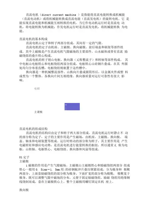
电刷主谡极直流电机的组成结构直流电机的结构应由定子和转子两大部分组成。
直流电机运行时静止不动的部分称为定子,定子的主要作用是产生磁场,由机座、主磁极、换向极、端盖、轴承和电刷装置等组成。
运行时转动的部分称为转子,其主要作用是产生电磁转矩和感应电动势,是直流电机进行能量转换的枢纽,所以通常乂称为电枢,山转轴、电枢铁心、电枢绕组、换向器和风扇等组成。
01定子主磁极i磁极的作用是产生气隙磁场。
主磁极山主磁极铁心和励磁绕组两部分组成铁心一般用0. 5inm〜1. 5mm用:的硅钢板冲片叠压钏紧而成,分为极身和极靴两部分,上面套励磁绕组的部分称为极身,下面扩宽的部分称为极靴,极靴宽于极身,既可以调整气隙中磁场的分布,乂便于固定励磁绕组。
励磁绕组用绝缘铜线绕制而成,套在主磁极铁心上。
整个主磁极用螺钉固定在机座上。
换向极换向极的作用是改善换向,减小电机运行时电刷与换向器之间可能产生的换向火花,一般装在两个相邻主磁极之间,山换向极铁心和换向极绕组组成。
直流电机驱动电路设计的一些知识
1、直流电机驱动电路设计简介
直流电机驱动电路是自动控制系统的主要控制元件,它能够通过改变
输入电压来调节输出功率,从而改变直流电机的转速和输出功率。
直流电
机驱动电路的设计要求全面考虑各种因素,以确保设备的可靠性、安全性
和稳定性。
直流电机驱动电路的设计与组态包括电源栅格设计、控制构成、系统电压控制及系统功率控制四大部分。
2、电源栅格设计
电源栅格设计是设计直流电机驱动电路的基础,是驱动系统的最重要
的部分。
它必须考虑驱动系统的电压等级、负载类型、负载电流大小和驱
动器的输出特性,以确保驱动系统的可靠性、安全性和稳定性。
经典的栅
格设计可以划分为触发部分、稳压部分和过渡部分,其中触发部分的电压
应尽可能高,以充分考虑系统噪声和外部干扰;稳压部分的电压设置由于
系统参数的不确定性,应选取一定的安全倍数;过渡部分应补充补偿改变
负载时产生的不稳定。
3、控制构成
控制构成是改变输入电压来控制直流电机转速和输出功率的核心部分,常用的控制方式有直流分量控制、串级控制、母线控制和反馈控制。
(1)直流分量控制是最基本的控制方式。
他励直流电动机建模及仿真报告人:本人 电力系统及其自动化一、模型描述及仿真要求一台他励直流电动机 T L =2Ω+Ωdtd 励磁电流为常值,试求电枢端点突然加110V 时的速度响应和电流响应。
已知R a =1Ω;La =1±10% H ;G af I f0=10N ·m 。
要求:1、给出直流电动机的数学模型2、画出直流电动机的仿真框图或给出相关程序代码3、给出直流电动机速度响应和电枢电流响应的的曲线及数据二、直流电动机数学模型1、他励直流电动机动态过程中电枢电流i a 、励磁电流i f 、转速Ω可用下列方程描述:⎪⎪⎪⎩⎪⎪⎪⎨⎧+Ω+Ω==+=Ω++=++=ΩLa f af e f ff f f f af a a a a a a a aa a T R dt d J i i G T dt di L R i u i G dtdi L R i e dt di L R i u 相应的上述时域方程在零初始条件下,其拉式变换,即频域数学模型为:⎪⎩⎪⎨⎧+Ω+Ω=+=Ω++=ΩL f af f f f f f f af a a a a a Ts R s Js s Ia s I G s sI L R s I s U s s I G s sI L R s I s U )()()()()()()()()()()()(2、此模型中励磁电流保持常值不变,即梳控。
在此前提下相应的频域数学模型简化为:⎩⎨⎧+Ω+=+Ω+Ω=Ω++=Ω++=ΩΩLL f af f af a a a f af a a a a a T s R Js T s R s Js s Ia I G s I G s I s L R s I G s sI L R s I s U )()()()()()()()()()()()(000 本模型中有:T L =2Ω+Ωdtd 变成频域方程即:)()12()(s S s T L Ω+=3、本模型中参数选取(1)已知R a =1Ω、G af I f0=10N ·m(2)La=1±10% H 此处选取为 La =1H (3)选定上面参数后,电枢回路时间常数Ta=La/Ra=1 ,为保证起动过程中无振荡过程,应使阻尼比ξ>1【1】,相应的即可得出a M T T 4>。
直流无刷电机的建模与仿真1. Introduction- Background and motivation- Objectives of the study- Scope and limitations of the study2. Literature review- Overview of DC brushless motors- Mathematical models of DC brushless motors- Comparison of different modeling approaches- Simulation techniques for DC brushless motors3. Modeling of DC brushless motor- Description of physical components and their interactions - Fundamental equations for the motor operation- Derivation of mathematical model for DC brushless motor - Simplified model for practical applications4. Simulation of DC brushless motor- Software platforms for motor simulation- Model validation using experimental data- Analysis of motor performance under different conditions - Optimization of motor design parameters5. Conclusion and future work- Summary of key findings- Limitations and suggestions for future research- Practical implications of the study for motor design and control.Chapter 1: Introduction1.1 Background and MotivationElectric motors are widely used in various industries and applications, from small appliances to large machines. DC brushless motors, also known as electronically commutated motors, have gained popularity in recent years due to their high efficiency, low maintenance, and improved performance compared to traditional DC brushed motors. DC brushless motors use electronic systems to commutate the stator windings, eliminating the need for brushes and resulting in less mechanical wear and tear.To effectively design and control DC brushless motors, it is important to have an accurate mathematical model that predicts motor behavior under different operating conditions. Such a model can be used to optimize motor design parameters, simulate motor performance, and develop advanced control strategies.1.2 Objectives of the StudyThe objective of this study is to develop a comprehensive mathematical model for DC brushless motors and validate its accuracy through simulation. The study aims to explore various modeling approaches and simulation techniques, and evaluate their effectiveness for predicting motor behavior under different conditions. The study also intends to investigate the practical implications of the model and simulation results for motor design and control.1.3 Scope and Limitations of the StudyThe scope of this study is limited to DC brushless motors operated under steady-state conditions, with a focus on the modeling and simulation of motor performance. The study does not cover the actual physical construction or manufacturing of DC brushless motors. The study is also limited to motors with reasonable power ratings, such as those used in household appliances or small industrial machines, and does not include very large motors used in heavy machinery or transportation.In summary, this study aims to develop an accurate mathematical model for DC brushless motors and validate its effectiveness through simulation. This study is limited to motors operated under steady-state conditions and focuses on motor performance modeling and simulation. The study will contribute to the understanding of DC brushless motor behavior and provide insights for motor design and control optimization.Chapter 2: Literature Review2.1 IntroductionIn this chapter, a review of existing literature on DC brushless motor modeling and simulation will be presented. The review will cover the different approaches and techniques used in previous studies, as well as the advantages and limitations of each approach.2.2 Modeling ApproachesModeling is the process of developing a mathematical description of a system or process based on its physical properties and behavior. There are several approaches to modeling DC brushlessmotors, including analytical, numerical, and empirical models.Analytical models use mathematical equations and principles to describe the behavior of DC brushless motors. These models are based on the physical properties of the motor and its components, such as the magnetic field, stator windings, and rotor position. Analytical models can be relatively simple, such as a simple voltage-current model, or more complex, such as a dynamic model that includes multiple subsystems and feedback loops. Analytical models are useful for understanding the fundamental behavior of DC brushless motors, but may not always capture the full range of motor performance.Numerical models use computational techniques to simulate the behavior of DC brushless motors. Numerical models are based on algorithms and numerical methods, such as finite element analysis or finite difference methods, to solve complex equations and simulate motor performance. Numerical models can be used to simulate complex behavior, such as nonlinear effects and dynamic response, but can be computationally intensive and require significant computational resources.Empirical models are based on experimental data and empirical relationships between motor variables, such as voltage, current, speed, and torque. Empirical models can be useful for predicting motor performance under specific conditions, but may not be as accurate or generalizable as analytical or numerical models.2.3 Simulation TechniquesSimulation is the process of using a model to predict or replicate the behavior of a system or process. Simulation of DC brushless motors can be performed using various techniques, including finite element analysis, simulation software, and hardware-in-the-loop simulation.Finite element analysis involves using numerical methods to discretize the motor into small elements and solve governing equations to predict magnetic field distributions and motor performance. Simulation software, such as MATLAB simulink or LabVIEW, can be used to simulate motor behavior based on a mathematical model. Hardware-in-the-loop simulation involves connecting a real motor with a simulated model to recreate realistic operating conditions and evaluate the performance of the motor.2.4 Advantages and LimitationsAnalytical models provide a fundamental understanding of DC brushless motor behavior and can be useful for designing control strategies and optimizing motor parameters. However, analytical models may not always capture the full range of motor performance and may require significant computational resources. Numerical models can simulate complex behavior and provide accurate predictions of motor performance. However, numerical models can be computationally intensive and require specialized software and hardware.Empirical models can be useful for predicting motor behavior under specific conditions, but may not be as accurate orgeneralizable as analytical or numerical models. Empirical models may also require significant experimental data collection and processing.Simulation techniques, such as finite element analysis, simulation software, and hardware-in-the-loop simulation, can provide a platform for evaluating motor performance under different conditions and developing advanced control strategies. However, simulation techniques may require specialized hardware and software, as well as significant computational resources.In summary, DC brushless motor modeling and simulation has been approached using various methods, including analytical, numerical, and empirical models, as well as different simulation techniques. Each approach has its advantages and limitations, and the choice of approach depends on the specific application and objectives of the study.Chapter 3: DC Brushless Motor Control Strategies3.1 IntroductionDC brushless motors are widely used in various applications, such as electric vehicles, industrial automation, and robotics. To achieve optimal motor performance, efficient and accurate motor control strategies are crucial. In this chapter, various control strategies used for DC brushless motor control will be discussed, including sensor and sensorless control, proportional-integral-derivative (PID) control, and field-oriented control (FOC).3.2 Sensor and Sensorless ControlDC brushless motors can be controlled using either sensor or sensorless control techniques. Sensor control uses position sensors, such as Hall effect sensors or encoders, to provide feedback on the rotor position and velocity. This feedback is used to generate control signals to control the motor. Sensor control provides accurate and reliable position sensing, but requires additional hardware and may be more expensive.Sensorless control techniques use algorithms to estimate the position and velocity of the rotor based on signals from the motor and control inputs. Sensorless control is cost-effective and eliminates the need for additional hardware, but may be less accurate and reliable than sensor control.3.3 Proportional-Integral-Derivative (PID) ControlPID control is a common control technique used for DC brushless motor control. PID control uses feedback from the motor to generate control signals that adjust the motor parameters, such as shaft speed or torque, to achieve the desired performance. PID control uses three parameters: proportional gain, integral gain, and derivative gain, to generate the control signals. The proportional gain determines the immediate response of the motor, the integral gain eliminates steady-state errors, and the derivative gain provides a quick response to changes in motor behavior.PID control is simple, effective, and widely used in various applications. However, PID control may not be suitable for complex systems, such as variable load or non-linear systems thatrequire advanced control techniques.3.4 Field-Oriented Control (FOC)Field-oriented control (FOC) is an advanced control technique used for DC brushless motor control. FOC uses mathematical models to control the magnetic field of the motor, rather than individual currents or voltages. FOC provides faster response, higher efficiency, and better accuracy than PID control. FOC also provides smoother torque and reduces motor noise and vibration.FOC requires advanced computational resources and specialized hardware to implement. FOC may also be more complex and difficult to implement than simpler control techniques.3.5 Comparison of Control StrategiesThe choice of control strategy depends on the application requirements, the complexity of the system, and the available resources. Sensor control provides accurate and reliable position sensing, but requires additional hardware and may be more expensive. Sensorless control is cost-effective and eliminates the need for additional hardware, but may be less accurate and reliable than sensor control.PID control is simple, effective, and widely used in various applications. However, PID control may not be suitable for complex systems that require advanced control techniques. FOC provides faster response, higher efficiency, and better accuracy than PID control, but requires advanced computational resourcesand specialized hardware to implement.In conclusion, DC brushless motor control techniques, including sensor and sensorless control, PID control, and FOC, provide various options for controlling motor performance. Each control strategy has its advantages and limitations, and the choice of approach depends on the specific application requirements and available resources.Chapter 4: Motor Control Hardware and Software4.1 IntroductionThe performance of DC brushless motors depends on the control hardware and software used to convert electrical signals into mechanical movement. This chapter discusses the hardware and software components required for effective DC brushless motor control, including power electronics, microcontrollers, and software algorithms.4.2 Power ElectronicsPower electronics are essential components in DC brushless motor control systems. Power electronics are used to convert the AC or DC input voltage into the pulsed DC signal required to drive the motor. The power electronics also regulate the voltage and current to maintain the desired motor speed or torque.Power electronics consist of four main components: power transistors or MOSFETs, diodes, gate drivers, and capacitors. Power transistors or MOSFETs are used to switch the voltage tothe motor on and off to create the desired pulse signals. Diodes are used to control the back EMF from the motor. Gate drivers provide the necessary voltage and current to switch the power transistors or MOSFETs. Capacitors are used to filter the output voltage to ensure a smooth and stable output.Power electronics influence the performance and efficiency of DC brushless motor control systems. High-quality, reliable power electronics are crucial for achieving optimal motor performance with minimal energy loss.4.3 MicrocontrollersMicrocontrollers are specialized computer chips that control the operation of electrical and mechanical systems. Microcontrollers are the brain of the DC brushless motor control system, providing computational power to perform control algorithms and communicate with external devices.Microcontrollers are responsible for generating and interpreting the signals required to drive the power electronics, receive and process feedback signals from the motor, and calculate the necessary control signals to achieve the desired motor performance. They also communicate with external devices, such as sensors, displays, or communication modules, to receive input signals or provide output signals to external devices.Microcontroller selection depends on the specific motor control requirements, such as operating frequency, computational speed, input and output interfaces, and memory requirements. A widerange of microcontroller models are available, with varying features and capabilities.4.4 Software AlgorithmsSoftware algorithms are used to generate the necessary control signals to drive the motor based on feedback from the motor and control inputs. Control algorithms include simple techniques, such as PID control or complex techniques, such as FOC.The control algorithms determine how the microcontroller processes the input signals and generates the output signals. The algorithms incorporate mathematical models that describe the electrical and mechanical behavior of the motor, such as the motor's inductance, resistance, and magnetic field.Software algorithms also incorporate other features such as speed limits, current limits, overcurrent or over-temperature protection, and feedback filtering, depending on the specific motor control requirements.4.5 Motor Control System IntegrationThe effective integration of power electronics, microcontrollers, and software algorithms is crucial for achieving optimal DC brushless motor performance. The components should be selected to meet the specific motor control requirements, such as power output, motor size, and operating frequency. The components should be appropriately sized, properly installed, and effectively interfaced to ensure reliable and efficient motor operation.Motor control system integration requires specialized expertise in electrical and mechanical engineering, as well as software development. Effective integration also requires careful testing and validation to ensure optimal motor performance and reliability.In conclusion, DC brushless motor control hardware and software are essential components for converting electrical signals into mechanical movement. The components, including power electronics, microcontrollers, and software algorithms, must be appropriately selected and integrated to achieve optimal motor performance. Effective motor control system design requires specialized expertise and careful testing and validation to ensure reliable and efficient motor operation.Chapter 5: Applications of DC Brushless MotorsDC brushless motors have become increasingly popular in recent years due to their high efficiency, reliability, and compact size. They are used in a wide range of applications, from small consumer electronics to industrial machinery. This chapter discusses some common applications of DC brushless motors.5.1 Consumer ElectronicsDC brushless motors are used in many consumer electronics products, including fans, cooling systems, and small appliances. They are ideal for these applications due to their small size, low noise, and high efficiency. Common consumer electronics applications include:- Computer fans and cooling systems- Handheld power tools (e.g., cordless drills, screwdrivers)- Electric shavers- Hair dryers- Vacuum cleaners5.2 Automotive ApplicationsDC brushless motors are becoming increasingly popular in the automotive industry due to their high efficiency and low noise. They are used in a wide range of applications, from small parts to main propulsion systems. Some common automotive applications include:- Electric power steering- Brake systems- Cooling fans- Hybrid and electric vehicle propulsion systems5.3 Aerospace ApplicationsDC brushless motors are also used in aerospace applications due to their high efficiency and low weight. They are used in a wide range of applications, including:- Actuators for control surfaces (e.g., ailerons, flaps)- Landing gear actuation systems- Fuel pump systems- Cabin ventilation systems5.4 Industrial ApplicationsDC brushless motors are commonly used in industrial applications due to their durability and reliability. They are used in a wide range of machinery, from small motors to large heavy-duty motors. Some common industrial applications include:- Conveyor systems- Machine tools (e.g., lathes, mills)- Packaging machinery- Pumps and compressors- Robotics5.5 Medical ApplicationsDC brushless motors are used in many medical applications due to their low noise, high efficiency, and accuracy. They are used in a wide range of equipment, including:- Dental drills- Surgical tools- Prosthetics- Diagnostic equipment (e.g., MRI machines)In conclusion, DC brushless motors have become increasingly popular in many industries due to their high efficiency, reliability, and compact size. They are used in a wide range of applications, from small consumer electronics to industrial machinery, as well as in aerospace and medical applications. DC brushless motors areideal for applications that require high efficiency and low noise, as well as for applications that require durability and reliability.。
直流串励电动机的建模与仿真摘要直流串励电机是需要高转矩/速度之比为机电应用的首选。
本文描述了系统的设计和实现一种开环直流电机的速度控制,这是基于一个微控制器和IGBTs。
不断尝试的设计既昂贵又费时。
这样的问题就解决了这里利用模拟工具,可以预测动态行为系统的机械和电子组件组成的。
沿着纸的模拟显示提供令人满意的协议与实验室的测量结果。
简介直流串励电机牵引通常应用需要高扭矩/速度之比的情况。
这些都是电动轮椅,高尔夫球车、升降机、起重机、致动器的武器等。
[8]。
在一个典型的应用包括人类操作员驾驶一台直流电机通过一个油门踏板或一根杆。
电子系统规范电力输入一部电机按照踏板或杠杆的立场,习惯上被称为速度控制。
这样的一个系统应用在开环或是闭环情况下[8]。
而闭环系统应用要求精度高,有很多情况下的开环系统就够了。
本文是关于后者。
一个典型的直流电机的速度控制往往具有其内在的讯号产生和处理模拟电路和功率驱动阶段MOSFET模块由几个平行[1]。
这个典型的控制,可改善其模拟功能取代或优势互补与数码照片,除此之外,每个平行布置,替代mosfet 与一个单一的IGBT模块[9]。
改进后的控制也因此结果更可靠、低成本和更简单的生产。
一种开环的数字速度控制的基础上,最后提出了一种IGBTs和这里发展起来的。
本文的主要目的,不过是呈现方法论受雇于这些作者为开发出的原型提出工作速度控制。
设计原型通常是实现机电由一个尝试和错误的过程,其中,大部分是非常昂贵又费时。
它提出了在此可以减轻弊端,通过合理结合计算机模拟本质上和实验室测验。
结合模拟的电动马达和它的速度控制做成很简单的模型运用为电机和/或为电子控制模块[第1、8、12]。
这里的工作报告,详细电机模型开发的。
然后,该模型为达到调整好很近的模拟和匹配的实际性能试验台被作为测验电机。
后来,模型的构建提出了速度控制模型的使用厂家提供其组成的电子装置。
最后,合模拟了电机和电机速度控制运用于精炼和调试该控制器设计,甚至在它的建模之前。
1•直流电机 (3)2•状态空间表达式 (6)3•对角标准型及相关分析 (7)4•系统状态空间表达式求解 (8)5•系统能控性和能观性 (8)6•系统输入输出传递函数 (9)7•两种方法判断开环稳定性 (9)8•闭环极点配置 (10)9•全维状态观测器设计 (13)10.带状态观测器的状态反馈控制系统的相关跟踪图 (17)10•带状态观测器的闭环状态反馈系统相关分析 (21)11结束语 (22)现代控制理论基础结课作业选题:直流电机模型姓名:班级:测控1003 学号:201002030313第I条1直流电动机的介绍节1.01 1.1研究的意义直流电机是现今工业上应用最广的电机之一,直流电机具有良好的调速特性、较大的启动转矩、功率大及响应快等优点。
在伺服系统中应用的直流电机称为直流伺服电机,小功率的直流伺服电机往往应用在磁盘驱动器的驱动及打印机等计算机相关的设备中,大功率的伺服电机则往往应用在工业机器人系统和CNC铣床等大型工具上。
[1] 节1.02 1.2直流电动机的基本结构直流电动机具有良好的启动、制动和调速特性,可以方便地在宽范围内实现无级调速,故多采用在对电动机的调速性能要求较高的生产设备中。
直流伺服电机的电枢控制:直流伺服电机一般包含3个组成部分:①磁极:电机的定子部分,由磁极N- S级组成,可以是永久磁铁(此类称为永磁式直流伺服电机),也可以是绕在磁极上的激励线圈构成。
②电枢:电机的转子部分,为表面上绕有线圈的圆形铁芯,线圈与换向片焊接在一起。
③电刷:电机定子的一部分,当电枢转动时,电刷交替地与换向片接触在一起。
直流电动机的启动电动机从静止状态过渡到稳速的过程叫启动过程。
电机的启动性能有以下几点要求:1)启动时电磁转矩要大,以利于克服启动时的阻转矩。
2)启动时电枢电流要尽可能的小。
3)电动机有较小的转动惯量和在加速过程中保持足够大的电磁转矩,以利于缩短启动时间。
直流电动机调速可以有:(1)改变电枢电源电压;(2)在电枢回路中串调节电阻;(3)改变磁通,即改变励磁回路的调节电阻 Rf 以改变励磁电流。