扣压机
- 格式:doc
- 大小:72.00 KB
- 文档页数:4

扣压机的工作原理
扣压机是一种用于连接和固定金属板材的设备。
它的工作原理基于通过施加一定的压力将两个或多个金属板材按照一定的形状和大小进行连接。
具体来说,扣压机主要包括以下几个部件:
1. 液压系统:扣压机通常采用液压系统作为驱动力源。
液压系统由液压泵、液压缸、液压阀等组成,通过控制液压阀调节液压泵的输出压力和流量,进而控制液压缸的工作状态。
2. 工作台:扣压机的工作台用于支撑和固定金属板材,在连接过程中提供必要的支撑和定位。
3. 扣件和模具:扣件是连接金属板材的重要部件,一般由螺栓、螺母、螺柱组成。
扣件与模具配合使用,模具的形状和尺寸决定了连接件的结构形态。
扣压机的工作步骤如下:
1. 调节液压系统:根据所需的连接压力和流量,调节液压泵和液压阀的参数。
2. 定位金属板材:将待连接的金属板材放置在工作台上,并进行精确定位。
3. 安装连接件和模具:在金属板材上安装扣件和与之配合的模
具,确保连接过程中的结构和尺寸要求。
4. 开始连接:通过操作控制系统,在确定好的连接点上使液压系统工作,使液压缸的活塞向下运动,并施加一定的压力到连接件上。
5. 完成连接:当连接压力达到要求后,保持一段时间使连接完全固定。
然后,释放液压压力,打开液压系统,将液压缸的活塞复位。
通过上述步骤,扣压机能够将金属板材进行可靠、牢固的连接。

软管扣压机安全操作规程1综合说明1.1该装置为扣压软管专业之用,只供受过专业培训的专业人员操作,操作人员应了解此装置在运转时的危险性!1.2模具的开度应比软管外径大6mm,以便把软管放入模具内扣压,因此在换模具与扣压装置时必须按操作规程及以下注意事项进行:1.2.1机器运行时严禁将手放入模具内;1.2.2当机器运行时,手应尽量远离扣压处以免伤手;1.2.3正常工作期间不得随意触动任何按钮;1.2.4非专业电气操作人员不得拆开配电盒:高压、危险;1.2.5当用快换工具换模具时,应握住工具,以保证手没有伸到模具中。
2操作控制2.1起动、卸载装置用来起动和停止电机;2.2按下扣压按钮,模具将收缩到预先设置的扣压直径;2.3回缩按钮,当按此按钮时,模具将回缩到最大位置;2.4扣压直径刻度盘,用于调整扣压后的最终尺寸;2.5模具范围表格,每一模具都有一个扣压直径范围的调整值。
3测试装置运动控制3.1起动电机;3.2设置扣压直径刻度到0.0;3.3第一次扣压时,缸体中的气体使模具无规则运动,需使电机运动几分钟后才会达到均匀的运动;3.4为避免事故,应保证模具间无其他杂物;3.5如果模具没有任何方向的移动,电机转向错误,应改换两相电源。
4模具的选择只能使用扣压机所带的原装模具,而且只有符合用户技术参数的装置才适用此扣压直径,每个模具都有自己的扣压直径范围。
只能按正确的模具进行扣压,才能保证尽可能好的扣压效果。
扣压直径标在每个模具上,除标准模具外,还有特殊范围的模具。
我公司所用模具型号及参数见下表(扣压机上有相同表格)模具型号 收拢后内径 模块长度 内径变化范围 备注 14# Ф14 55 Ф14-1616# Ф16 55 Ф16-1919# Ф19 55 Ф19-2323# Ф23 55 Ф23-2727# Ф27 70 Ф27-3131# Ф31 70 Ф31-3636# Ф36 75 Ф36-4141# Ф41 75 Ф41-4747# Ф47 85 Ф47-545模具的安装用一个快换工具能很快的将模具装在主模具内。

移动便携式压管机(修理、小批量型)
Uniflex offers astrong and compentitiive range of crimping machines.Those are easy,safe to use and guarantee exactness and reliability.
uniflex提供一系列性能优异且价格优惠的压管机;它操作简单、安全,同时具有精
确性和可靠性。
SM1 SM2 HM200 HM290ecoline
S6.2 S6.2ecoline S8i/s10i HM220B
◆低摩擦轴承,无须润滑,油摩擦损失比常规低20%。
Slide Bearings, no servce and20% less friction loss. ◆静音接头和内置齿轮泵降低了工作哨声。
NO iseless coupling or int-ernal gear pump to reduce noise levels. ◆控制系统连接拔插简便易行。
Easy plug-in/plug-out Con-trol systems. ◆ 在钟形和扣压爪和模具及扣压爪周围,工作空间实现了最优化设计。
Work space optimized:between front plate and dies and around machine head.
移动便携式压管机(技术参数)
Technical datd/
技术参数 SM1 SM2 HM200 HM290 S6.2 S8i/s10i HM220B。

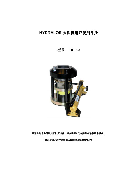
HYDRALOK扣压机用户使用手册型号:HE325承蒙选购本公司的胶管扣压设备,深表感谢!为使您能有效使用本设备,请在使用之前仔细阅读本说明书并妥善保管好!目录CONTENTS页码Page3. 产品质量保证说明Warranty conditions4. 公司声明Declaration of conformity5. 安全操作条款Safety regulations6. 技术数据Technical Data6. 装卸/搬运注意事项Handling/transport6. 预备检测Preliminary checks6. 照明Lighting6. 日常维护Routine maintenance7. 操作指南Operating instructions7. 刻度Calibration11. 刻度表Calibration chart (two piece fittings)12.刻度表Calibration chart (one piece fittings)14. 其他部件Spare parts15.可选用的其他气/液压加压系统Optional Air/Hydraulic power pack (700 Bar)17. 可选用的电动加压系统(220/240-1-50 or 12伏直流电volt DC)Optional Electrical power pack产品质量保证说明WARRANTY CONDITIONS所购机器在发货前均经过严格检测。
Please note that all machines undergo strict testing before shipment.1.购买之日起,所购机器享有12个月的质保期。
本公司保留要求客户出示销售发票副本的权力。
All machines are warranted against any defects for a period of 12 MONTHS starting from the date of delivery to the customer. The company reserves the right to require a copy of the sales invoice.2.该质保声明包括在质保期内享有维修和/或更换任何确实存在缺陷的零部件的权益。

FINN-POWER扣压机一览P 16 HP 手动式◆最大胶管直径1”◆扣压范围至:10-45mm◆用微分尺控制扣压量◆扣压能力:95吨◆适用于无电力的供应场所P 16 AP 气动式◆最大胶管直径1”◆扣压范围至:10-45mm◆扣压力度:95吨◆利用压缩空气操作◆适用于无电力的供应场所P 20 HP 手动式◆最大胶管直径1-1/2”◆扣压范围至10-61 mm◆扣压能力:137吨◆用简单的针尺显示扣压尺寸◆适用于无电力的供应场所P 20 AP 气动式◆最大胶管直径1-1/2”◆扣压能力:137吨◆扣压范围至10-61 mm◆137吨扣压力度◆适用于无电力的供应场所P 20 CS 电瓶式◆最大胶管直径1-1/2”◆扣压范围至10-61mm◆使用MS型操控器◆可采用12或24伏特电瓶◆适用于无电力的供应场所P 32 CS 电瓶式◆最大胶管直径2”◆扣压范围至10-87mm◆扣压力度:200吨◆使用MS型操控器◆可采用12或24伏特电瓶FINN-POWER扣压机一览P 20 手动半自动式◆最大胶管直径1-1/2寸.◆扣压范围至10-61mm◆单项电机亦可提供◆扣压力度:137吨◆芬宝的最新操作和实用设计。
P 21 手动式◆最大胶管直径1-1/2寸.◆扣压范围至10-61mm◆加大的扣压机头和模具扩张◆张度方便扣压弯曲接头P 32 手动半自动式◆最大胶管直径2”寸.◆扣压范围至10-87mm◆扣压力度:200吨◆芬宝最新半自动操作模式◆芬宝的最新操作和实用设计P 51 手动数字液晶式◆最大胶管直径2-1/2寸.(工业管最大4寸)◆扣压范围至10-120mm◆扣压力度:280吨◆最坚固的桌面型扣压机和半自动操作模式◆加大的扣压机头和模具扩张◆张度方便扣压弯曲特殊接头低产量系列扣压机在操作方便、性能和可靠准确效果等方面都获得用户们的赞许。
在同类的机器中被列为坚固和强力的产品;新设计中添加原来双键操作模式;改为半自动单件操控模式。
Copyright 2016 by Lillbacka Powerco Oy. All rights reserved.Translation of the original instructions.No part of this documentation may be reproduced, copied or transmitted in any form, or by any electronic, digital or other means, without permission in writing from Lillbacka Powerco (referred to herein as the “Company”). This includes photocopying and information storage and retrieval systems. The material in this documentation is subject to change without notice.Keep this manual for future needs.The machine has been designed for crimping hose fittings. Lillbacka Powerco shall not be held liable for any product which has been crimped on the machine. The machine has been designed to operate in room temperature, in dry indoor conditions and in sufficient illumination. Using the machine for any other purpose is not allowed without written consent from the factory.CONTENTSCONTENTS (5)GENERAL (6)TRANSPORT (6)STORAGE (6)MOUNTING (6)HELP PROTECT OUR ENVIRONMENT (7)DISPOSAL OF THE PACKING MATERIAL (7)DISPOSAL OF YOUR OLD MACHINE (7)WARNINGS (7)GENERAL (7)DANGER ZONES (8)COMMISSIONING (9)OIL FILL (9)ELECTRICAL CONNECTION (9)RUNNING-IN (10)GREASING (10)QUICK FIX-PACKAGE (10)OPERATION (11)CONTROL IDENTIFICATION (11)TEST RUN (11)SELECTING THE DIE SET, P20 MODEL (12)SELECTING THE DIE SET, P32 MODEL (12)INSTALLING THE DIE SET (13)QUICK CHANGE (13)CHANGE OF A SINGLE DIE (13)SETTING THE CRIMPING DIAMETER (14)CRIMPING (15)FOOT PEDAL (15)IF THE MACHINE DOES NOT WORK (16)PREVENTIVE MAINTENANCE (17)CLEANING (17)GREASING (17)CYLINDER PROTECTION INSERTS (18)OIL CHANGE (18)FILTER CHANGE (18)MASTER DIE SPRING CHANGE (19)PRESSURE PIPES (19)RE-CALIBRATION OF CRIMPING DIAMETER DIAL (19)GUARANTEE (20)TECHNICAL DATA (21)TECHNICAL DATA P20NMS (21)TECHNICAL DATA P32NMS (22)DECLARATION OF CONFORMITY (23)MAINTENANCE HISTORY / HUOLTOHISTORIA (24)GENERALFINN-POWER crimping machines are electrically operated hydraulic crimping machines for hydraulic hose assemblies. Machines are designed for single piece- and low production.The crimping machine comprises a crimping head, a hydraulic unit which serves as machine frame . FINN-POWER crimping machine is normally delivered with a 3-phase electric motor.TRANSPORTThe packed machine is transported on a pallet, which is easy to move and lift by a fork-lift truck. After unpacking, the machine can be lifted using a hoisting belt.Size of package: x = 75, y = 60, z = 78 cm.STORAGEThe manufacturer has protected the machine against corrosion by using the Zerust method. The machined parts have been treated with Axxatec 77C protective agent. A Zerust vapor capsule has been put into the electric box, and the machine has been packed into a bag made of Zerust film.The protection is effective for months if the package is not opened. After opening it, the protection of the wrapping film ceases. If the machine is not yet brought into use, it must bereprotected against corrosion. The machine is to be stored in dry indoor conditions.Remove the protective agent according to the instructions enclosed in the package.MOUNTINGThe adjacent picture shows an appropriate way to lift the machine after it has been unpacked.It is recommended to mount the machine on a Finn-Power table. Before mounting, the table must be screwed on the floor with four M12 wedge anchors. Boreholes in the floor: Ø 12 mm, depth 55 mm.When the machine is mounted on a Finn-Power table, the four shoes under the machine are removed.The table with assembly instructions is packed separately.The crimper may be installed on some other table as well, provided it is sturdy and broad enough or it has been fastened on the floor so that it cannot fall over. Check the machine weight from the type plate. Furthermore, there must be a hole in the table to enable emptying the oil tank through the drain plug.Mount the machine in a location that gives enough working space, 900 mm (3 ft) round the machine. The sufficient lightning in machine surroundings is also needed to ensure safe working.Pakkaus1.epsHELP PROTECT OUR ENVIRONMENT DISPOSAL OF THE PACKING MATERIALThe transport and protective packing is mostly manufactured from the recycled or recyclable materials. Please check local environmental regulations before disposing of packing materials. Rather than throwing these materials away, please take them to your community recycling centre.DISPOSAL OF YOUR OLD MACHINEOld machines contain materials which can be recycled. Please contact your recycling centre of scrap merchant before discarding the appliance. Handle the waste oil and filters according to law.WARNINGSGENERALUse only original Lillbacka Engineered Finn-Power die sets in your Finn-Power crimping machines. Installing and using third party die sets are voiding any warranties, and all liability what so ever nature is rejected. Using third party dies sets will be done solely on users own risk and recourse.Read the instructions thoroughly to secure safe and correct operation of the machine.The machine is intended for professional use. It is to be operated only by a trained operator who has understood the dangers involved in the operation. The machine is designed to operate in room temperature, in dry indoor conditions and in sufficient illumination.Openings between the dies exceed 6 mm, thus being large enough to let fingers go between the dies and get crimped. It is, therefore, ABSOLUTELY necessary to follow operating instructions and warnings indicated by the stickers on the machine when changing dies and crimping fittings.The cover- and protection plates protect the operator from crimping- and other possible hazards.It is recommended to use appropriate protective eyewear, gloves and safety shoes during operation and maintenance.Test the function of the emergency stop push buttons every day!DANGER ZONESWARNING 3 WARNING 4WARNING 5(P32 model)COMMISSIONINGOIL FILLFill the oil tank to centre line of the indicators in the dipstick with hydraulic oil like Shell Tellus T46 or equivalent. Volume of the tank is 27 litres.It is recommended to pump the oil into the tank through a 20 filter, because new oil in drums is not pure. If any oil has run out on the floor, wipe it away.ELECTRICAL CONNECTIONCAUTION! Check that the machine voltage (see type plate) is equal to your supply voltage. For proper installation to local code, consult a licensed contractor.Bring the supply cable through the hole on the rear of the machine and guide it through the hole on the rear of the electric box. Secure the cable with a stress relief plug. The minimum size for the cable:3-phase: Connect the phase conductors to the respective L1, L2 and L3 terminals in the supply disconnecting device. Connect the earth connection to the ground terminal on the fixing plate. Check the connection against the wiring diagram enclosed in the spare parts list.Check that the motor rotation is parallel with the arrow close to the motor. In case the motor rotates in wrong direction, two phase conductors in the supply disconnecting device must be interchanged.1-phase: Connect the phase and the neutral to the respective terminals in the supply disconnecting device. Connect the earth connection to the ground terminal on the fixing plate. Check the connection against the wiring diagram enclosed in the spare parts list.RUNNING-INRecommended running in period for a new machine is 50 000 crimps. It will be enough if the greasing cycle is halved during the running in period. The purpose of frequent greasing is to ensure that there is always grease enough between the sliding surfaces. Due to the surface pressure the grease sinks in to the metal pores ensuring good sliding properties for the machine’s lifetime. During the running in period grease the machine after every 1000 crimps.GREASINGThe master dies of the machine has been greased at the factory after the final testing. However, the grease may have dried during the transportation and storing and therefore the machine should be greased according to the operating instructions before commissioning.Greasing of the master dies is an important maintenance procedure which should be made regularly. The adverse working environment and crimping volume have a special effect on the need for maintenance. Preventive maintenance and proper use help to ensure trouble-free operation of the machine. It is recommended to grease the machine after every 2000 crimps, except during the running in period when the greasing should be done after every 1000 crimps.QUICK FIX-PACKAGEIncluded with the machine, there is a Quick Fix-package which has some basic parts for this machine model.OPERATIONThe crimping machine is switched on by turning the supply disconnecting device. However, the motor won’t run until the crimping- or retraction -push button is pressed. The motor stops automatically and the indicator light starts illuminate, if the machine is not used in 6 seconds. The motor springs to life when the crimping- or retraction -button is repressed.CONTROL IDENTIFICATION1. Supply disconnecting device for starting and stopping the machine. The device is used to separatethe machine from power supply. However, the machine can be made dead only by disconnecting the plug or supply cable from the mains.2. As long as the crimping push-button is depressed, the dies will close until the button is released or thepreset crimping diameter is reached.3. Retraction button. When depressed and held down, the dies will open until the button is released orthe maximum mechanical retraction is reached.4. Crimping diameter dial.5. Emergency stop.6. Die chart with crimping diameter range for each die set and corresponding dial adjustment values isdelivered together with the machine.7. Holder for die change tool.8. Foot pedal(option). Crimping pedal 8.1 and retraction pedal 8.2. See page 15.The main operating area of the machine is in front of the controls.TEST RUN∙Start the machine.∙Set the crimping diameter dial to 0.0.∙During the first crimping cycles air in the cylinders may make the piston/dies move irregularly and at high speed. Cycle the press a few times till the motion becomes even.∙To avoid accidents, make sure that there are no foreign objects between the dies.∙In case the dies do not move in either direction, the motor rotates in wrong direction. Correct by interchanging two phase conductors in the supply disconnecting device.SELECTING THE DIE SET, P20 MODELUse only original Finn-Power die sets in Finn-Power crimping machines .Refer to the fitting manufacturer's specifications for proper crimping diameter for the fitting.Each die set has its own crimping range. Follow it to assure the roundest possible crimping result. The minimum crimping diameter D is marked on each die set.Example: with die set No 18013/10 the minimum crimping diameter is 10 mm.D L Die set No10 55 18013/10 10...12 mm 12 55 18013/12 12...14 mm 14 55 18013/14 14...16 mm 16 55 18013/16 16...19 mm 19 55 18013/19 19...23 mm 23 55 18013/23 23...27 mm 27 70 18013/27 27...31 mm 31 70 18013/31 31...36 mm 36 75 18013/36 36...41 mm 41 75 18013/41 41...47 mm 47 85 18013/47 47...54 mm 54 85 18013/54 54…61 mmSELECTING THE DIE SET, P32 MODELUse only original Finn-Power die sets in Finn-Power crimping machines .Refer to the fitting manufacturer's specifications for proper crimping diameter for the fitting.Each die set has its own crimping range. Follow it to assure the roundest possible crimping result. The minimum crimping diameter D is marked on each die set.Example: with die set No 18506/10 the minimum crimping diameter is 10 mm. D L Die set No Crimping range 10 55 18506/10 10 ... 12 mm 12 55 18506/12 12 ... 14 mm 14 55 18506/14 14 ... 16 mm 16 55 18506/16 16 ... 19 mm 19 55 18506/19 19 ... 22 mm 22 70 18506/22 22 ... 26 mm 26 70 18506/26 26 ... 30 mm 30 70 18506/30 30 ... 34 mm 34 75 18506/34 34 ... 39 mm 39 75 18506/39 39 ... 45 mm 45 90 18506/45 45 ... 51 mm 51 90 18506/51 51 ... 57 mm 57 100 18506/57 57 ... 63 mm 63 110 18506/63 63 ... 69 mm 69 110 18506/69 69 ... 75 mm 74 110 18506/74 74 ... 80 mm 78 110 18506/78 78 ... 87 mmIn addition to the standard dies, a wide range of special dies is available on request.INSTALLING THE DIE SETQUICK CHANGE (OPTION)An optional QC Tool Base enables storing die sets under the machine. The whole die set can be installed into the master dies with a quick change tool at one time.∙ Before installing dies, make sure that the master dies are clean.OPEN THE SUPPLY DISCONNECTING DEVICE PRIOR TO CLEANING DIES.∙ Set the crimping diameter dial at 0.0 and open the dies to the maximum retraction.∙ Insert the pins of the tool into the die set in the die table, turn the tool clockwise and pull the whole set out (Fig. 1, next page). ∙ Hold the handle of the quick change tool as shown in figures 1 and 2, and make sure your hand will not get between the dies. ∙Mount the die set between the master dies (Fig. 2) and start closing the dies.TO AVOID DAMAGING MASTER DIES, MAKE SURE THAT ALL DIE SET PINS HIT IN THEIR HOLES.∙ Close the master dies completely until the pins are locked in their places (Fig. 3). Remove the tool. The dies are now ready for use (Fig. 4). ∙ The die set is removed from the master dies in reverse order: close the dies, insert the tool into the die set, open the master dies and place the set back in to the die table.Fig. 1 Fig. 2 Fig. 3Fig. 4CHANGE OF A SINGLE DIE∙Open the dies to the maximum retraction. Open the supply disconnecting device. CAUTION! SUPPLY DISCONNECTING DEVICE SHALL ALWAYS BE OPENED DURING THE INSTALLATION OF THE DIES.∙ Prior to installing the dies, clean the contact surface of both the die set and master dies properly to avoid damaging the surfaces. ∙ Pull the pull pin in the master die with the tool delivered together with the machine (see figure). ∙ Insert the die with the retaining pin into the master die, die number always towards you. Release the pull pin. ∙ After installing all the dies, make sure they are straight and properly seated in the master dies.QC-homma.epsSETTING THE CRIMPING DIAMETERFrom the crimping diameter chart, delivered together with the machine, you can see the die set numbers and the corresponding crimping ranges. The upper section of the chart shows the corresponding dial position for each crimping diameter in the columns.Crimping diameters in the grey zone of the chart are not recommended to be used with the die set in question.The crimping diameter dial has been calibrated at the factory so that when the dial is set at 0.0, the resulting diameter will be the minimum diameter of the die set installed, i.e. with die set No 20-16 the crimping diameter will be 16 mm, No 20-19 gives a diameter of 19 mm etc. Each full turn clockwise of the adjusting knob of the dial will add 1 mm to the crimping diameter. Each division on the measuring scale corresponds to 1/100 mm.EXAMPLE: Manufacturer has specified a crimping diameter of 20.6 mm for the fitting. Select die set No 20-19 (min crimping diameter 19 mm) according to the die chart. Turn the dial to position 1.60 (upper scale 1, lower 60). This setting will give the crimping diameter 20.6 mm (19 + 1.6 mm).The machine has been calibrated at the factory with 40 bar pressure. This means that when you are crimping a fitting requiring 40 bar pressure, the measuring scale of the crimping diameter dial providesan accuracy of +/- 0.1 mm (possible elastic recovery of the fitting not regarded).When fittings requiring higher pressure are crimped, the crimping diameter may become larger than the value on the scale due to machine deflections. Then the crimping diameter has to be corrected by changing the scale value.The crimping diameter chart P20NMSThe crimping diameter chart 32 PMSCRIMPINGWHEN CRIMPING A FITTING, HOLD THE HOSE FAR ENOUGH TO AVOID CRIMPING YOUR HAND! DO NOT CRIMP THE EDGE OF THE DIE!The machine can be operated manually by using the crimping- and the opening -push buttons or with semi-automatism.1. Adjust the recommended crimping diameter.2. Press the crimping button until the dies hold the fitting lightly.3. Press the crimping button until the dies stop.4. Open the dies and remove the fitting.5. Check the crimping diameter.FOOT PEDAL (OPTION)As an alternative, a foot pedal can be installed in the foot pedal connection, e.g. when large fittings are crimped. The foot pedal enables holding the hose assembly with both hands.NOTE! The foot pedal is double pedal. One pedal for crimping and the other one for opening.1. Remove cover plate and remove the knock out from rear cover plate.2. Connect the foot pedal to the plug in the rear side of the electric box. Install cover plate.3. When the foot pedal is connected, dies will move as long as the foot pedal is pressed or till the set crimping diameter has been reached. The crimping movement can be interrupted by lifting the foot from the pedal. After reaching the crimping diameter dies are opened by using the other pedal. Dies can be also opened by using retraction button.keephose.epsIF THE MACHINE DOES NOT WORK…If the motor doesn’t start up1. To start up the machine, turn the switch completely to the left (0) and then to the uprightposition (I).2. If the problem is not disappearing, contact the service.If the motor starts up but th e dies don’t move1. Check the rotation of the motor.2. Check the oil level.3. Check that the dies are not already in close- or retraction position.If the machine leaks oil1. A new machine might leak a small amount of rust protection oil under the cylinder or under themachine.2. When the machine has been filled up with oil, some oil might have leaked inside the machineand then slowly under the machine.3. If the machine is in continuous use, some oil (0,1dl) might pass the seals and leak under thecylinder when the machine is stopped or when changing the die sets.If the machine’s power is not enough1. The lack of power might be caused by dry sliding surfaces. Grease the machine.2. Check that the coupling or the piece you are crimping is the size that the machine can crimp.The machine’s pressure relief valve opens and the dies stop when the maximum power of themachine has been reached.3. If the dies open up in normal speed but close slower and the machine is lacking crimpingpower, there is dirt in the hydraulic system which causes a leak in the valve. Contact theservice.4. The pressure relief valve of the machine has been adjusted at the factory. Do not open oradjust this valve in any way. If you suspect that the valve is not working properly, contact theseller of the machine.5. Make sure that there is oil enough in the tank.If the above measures do not help or machine with other problems, contact your service representative.If you contact the manufacturer or the distributor about the operating or service-problems, remember to give your crimping machine’s serial number and the type of the control.PREVENTIVE MAINTENANCE∙ The following maintenance operations can be performed by the operator according to the instructions below. However, electrical works and repairs like changing seals or the pump must only be carried outby a qualified specialist. PRIOR TO ANY SERVICING OPERATION, TURN THE SUPPLY DISCONNECTING DEVICETO POSITION '0' AND LOCK THE DEVICE.BEFORE CHANGING THE MOTOR CIRCUIT BREAKER OR UNDERVOLTAGE TRIP, DISCONNECT THE PLUG OR SUPPLY CABLE FROM THE MAINS! ∙ Open the dies to the maximum retraction before servicing.CLEANINGKeep the machine always clean from extra particles. Cleaning the machine ensures nice and safe operation. Wipe the machine with dry cloth or with soft paper. Do not use water, solvents or abrasives. Keep the machine always well-greased.Fig. 1Fig. 2The inner side of the crimping head can be cleaned with a small brush (Fig. 1 and 2.)NEVER USE COMPRESSED AIR FOR CLEANING!GREASING∙ Lubricate the inner surface of the conical flanges daily with FINN-POWER grease: order n:o 019302 ∙ Apply the grease to the conical surfaces at the front and back of the die with a small brush. ∙ Lubricate often with a small amount of grease rather than seldom with much grease. ∙ Do not grease the piston rod.Greas_32.epsCYLINDER PROTECTION INSERTSThe machine has four cylinder protection inserts between the lowest dies in the crimping head. These inserts protect the cylinder from dirt and falling parts.NOTE! Protection inserts have to be installed always between the lowest dies. Because the master dies try to rotate during the operation, the inserts have to be moved into correct places every now and then.Replace the inserts if they lose their resilience or if they don’t stay still in their places or if they don’t fill in their space properly.Purchase numbers: 20 model: 702933 32 model: 702932OIL CHANGE∙ Change hydraulic oil after the first 500 hours of operation and every 1000 hours or once a year thereafter. ∙ Oil tank volume: 27 litres.∙ Recommended oil: Shell Tellus T46 or equivalent.∙ Empty the tank of oil through the draining plug behind the tank. ∙ Handle the waste oil according to law.∙ Fill the tank to centre line of the indicators in the dipstick of the filling cap.∙ It is recommended to pump the oil into the tank through a 20 μ filter, because new oil in drums is not pure. ∙ If any oil has run out on the floor, wipe it away.FILTER CHANGE∙ Filter insert must be changed together with oil. ∙ Open the filter cover, unscrew the filter insert and remove it. ∙ Handle the old filter according to the law. ∙ Lubricate the seal of the new filter insert with hydraulic oil. ∙ Screw the filter insert on. ∙ Install the filter cover. ∙ Purchase number: 710424.32_styrofoams.jpgMASTER DIE SPRING CHANGEMaster die springs are wearing parts and therefore has to be replace after every 200 000 crimps. To replace the springs a special tools and -craftsmanship are needed. In order to get the master die springs replaced contact your Finn-Power representative.Warning:Do not use the machine if there are broken or twist springs in the machine. Broken or twist spring can damage the machine or cause personal injuries.PRESSURE PIPESReturn cylinders on both sides of the crimping head produce the piston movement backwards and simultaneous retraction of dies.Hydraulic pipes to the two cylinders are high-pressure pipes (275 bar). To prevent leakage, be careful not to damage these pipes and their connectors.In case you notice leakage in a connector, make sure it is properly tightened. Leaking pipes must be replaced immediately. DO NOT REPAIR PIPES!RE-CALIBRATION OF CRIMPING DIAMETER DIALNOTE: The crimping diameter dial has been calibrated at the factory during test run.1. Re-calibrate the crimping diameter withferrule (seamless steel tube), Ø 25 mm; wall2 mm, by using the die set No 20-19 (20model) or the die set 32-19 (32 model).2. Set the dial at 1.0, so that the crimpingdiameter will be 20 mm (see the adjacentpicture) and lock the dial. Crimp the ferruleand measure the real diameter.3. Remove the control dial knob (avoid to turnthe dial shaft at the same time).4. Open the dial lock lever and set the realdiameter into it (diameter of ferrule) relock itand install back.5. Turn the dial to right diameter and crimpanother ferrule. Now the machine has beencalibrated and the real diameter should bethe same than the diameter which state onthe dial. If not, repeat from point 2 and bemore careful when handling the dial.6. After the adjustment, the crimping result should be the minimum nominal crimping diameter of each dieset with the dial at 0.0.10-turn uusi.epsGUARANTEEThe machines produced by Lillbacka Powerco Oy are guaranteed against defects in material and manufacture. Within the limits of the guarantee, the defective part will be replaced with a new one, or when possible, repaired free of charge.The guarantee is valid for 12 months after commissioning, yet for a period not exceeding 18 months after delivery ex works Alahärmä, Finland.The guarantee does not compensate for damage due to improper use, overload, neglect, or normal wear. Working and travelling costs as well as freight charges caused by guarantee repairs are not covered by the guarantee.Guarantee repairs shall be carried out at Lillbacka Powerco Oy, Alahärmä, Finland, or by an authorized Finn-Power service. In case guarantee repair is demanded, the customer has to prove that the machine is under guarantee.LILLBACKA POWERCO OY DO NOT WARRANT FOR ANY INCIDENTAL OR CONSEQUENTIAL DAMAGES, OR FOR ANY OTHER LOSS, DAMAGE OR EXPENSE OF ANY KIND, INCLUDING LOSS OF PROFITS.TECHNICAL DATATECHNICAL DATA P20NMS3-phase 1-phaseCapacity in 1½ 1½Crimping diameter range *) Ø (mm) 10...61 10 (61)Max opening mm 25 25Pump l/min 8.6 2.8Max pressure bar 275 275Crimping force kN 1370 1370Theoretical production capacity **) per hour 1000 258Sound pressure level dB(A) 71 71Enclosure class IP 54 IP 54Closing speed of master dies mm/s 2.9 1Frequency 50 HzMotor power kW 3 1.5Voltage V / Current A ☐ 200 / 16 ☐ 230/ 12.6☐ 230 / 11.7 ☐ / /☐ 400 / 6.7☐ / /Frequency 60 HzMotor power kW / hp 3.6 / 4.9 1.5 / 2.0Voltage V / Current A ☐ 210 / 15.6 ☐ 230 / 12.5☐ 230 / 10.8 ☐ / /☐ 400 / 6.2☐ / /*) Special diameters and profiles to customer's specifications.**) 10 mm die travel.Overall dimensions:Weight 140 kg, excluding oil.READ THE INSTRUCTIONS THOROUGHLY TO SECURE SAFE AND CORRECT OPERATION OF THE MACHINE.TECHNICAL DATA P32NMS3-phase 1-phaseCapacity in 2 2Crimping diameter range *) Ø (mm) 10...87 10 (87)Max opening mm 33 33Pump l/min 11.4 2.8Max pressure bar 275 275Crimping force kN 2000 2000Theoretical production capacity **) per hour 850 200Sound pressure level dB(A) 71 71Enclosure class IP 54 IP 54Closing speed of master dies mm/s 2.6 0.6Frequency 50 HzMotor power kW 4 1.5Voltage V / Current A ☐ 200 / 20.5 ☐ 230/12.6☐ 230 / 15.5 ☐ / /☐ 400 / 8.6☐ / /Frequency 60 HzMotor power kW / hp 4.8 / 6.5 1.5 / 2.0Voltage V / Current A ☐ 210 / 20.2 ☐ 230 / 12.5☐ 230 / 15.2 ☐ / /☐ 400 / 8.2☐ / /*) Special diameters and profiles to customer's specifications.**) 10 mm die travel.Overall dimensions:Weight 190 kg, excluding oil.READ THE INSTRUCTIONS THOROUGHLY TO SECURE SAFE AND CORRECT OPERATION OF THE MACHINE.Declaration of conformityMaintenance history / HuoltohistoriaMaintenance history / Huoltohistoria。
胶管扣压机扣压模具维护保养内容先说说,为什么要给模具“保养”一下。
大家都知道,扣压机每天的任务是把胶管跟接头“扣死”,就像咱们穿鞋子一样,鞋带要绑好,才能保证走路不掉。
这个“扣压”工作如果不做对,就会出现各种小问题——漏气、接头松脱,甚至整条胶管报废。
所以呢,模具就是这其中的一个“决定性因素”。
如果模具上有脏东西,或者磨损了,扣压的质量就下滑,甚至可能卡住胶管,影响效率。
所以保养模具,就是为了解决这些潜在问题。
怎么保养呢?这就好比咱们平时要给车子做保养一样,定期检查,按时保养。
每次用完机器后,记得把模具清理干净。
别以为一擦就行,像油污、灰尘这些小东西,如果积得多了,它们就变成了大麻烦。
特别是那些胶水、油渍,时间久了容易粘到模具表面,清洁起来就麻烦了。
所以,清理时,最好用干净的布和专用的清洁剂,千万别用粗糙的东西刮,免得刮坏了表面。
说实话,一开始的细心,省得后面的麻烦。
清洁完,别急着放回去休息。
还得看模具有没有磨损。
看看模具的表面,检查一下是不是有裂痕,特别是使用一段时间后,那些看不见的小裂缝,可能一开始并不起眼,但时间一久,模具就会“罢工”。
一旦发现裂痕,就得赶紧更换或者修复。
模具可是个“敏感”家伙,稍微受点伤,扣压效果就打折扣了。
咱们就不能让它成了“病号”,对吧?然后,还有个关键的环节,就是要给模具“滋润”。
没错,给模具上点润滑油,保持它的流畅性。
像机器运转一样,不加油是会“卡壳”的。
所以,适当给模具上点润滑油,不仅能让它的使用寿命更长,还能提高扣压的精度。
涂抹时要均匀,别一大堆油涂在一个地方,这样反而影响模具的使用效果。
你要是担心漏油,那就小心一点,别多了,也别少了,适量就行。
保养还不止这些,模具的安装也得注意。
每次换模具时,要确保模具和机器之间的接触面是干净的。
说白了,扣压机的“脸”和模具的“脸”要干净才行,才能保持两者之间的良好接触,不然就会影响扣压效果,甚至导致设备故障。
别让模具闲着太久。
型号:YJK-120型:模具套数14:价格USD3000尺寸(长*宽*高)600*480*650扣压范围(内径):Φ6-Φ51(mm)扣压范围(外径):Φ14-Φ120(mm)最大直径120mm标准电压220v-380v 50hz扣压力;450t 系统压力31.5mpa六层胶管扣压尺寸最大51mm,工业软管64mm带电动脚踏板型号:YJK-80型模具数12 价格:usd3000扣压范围(内径):Φ51-Φ180(mm)扣压范围(外径):Φ80-Φ400(mm)六层胶管扣压尺寸最大51mm,工业软管51mm,最大直径80mm尺寸,(长*宽*高)600*480*600;含油重量220kg 扣压力450t, 系统压力31.5mpa标准电压220V-380V 50HZ带电动脚踏板型号:YJK-64Z型模具数11 价格usd6000 扣压范围(内径):Φ6-Φ64(mm)扣压范围(外径):Φ14-Φ120(mm)最大直径120mm六层胶管扣压尺寸最大64mm工业软管最大尺寸76mm尺寸(厚*宽*高)500*700*1450mm 标准电压380v 50hz电功率5.5 kw带电动脚踏板型号:YJK-64S型模具数10;单价扣压范围(内径):Φ6-Φ64(mm)扣压范围(外径):Φ14-Φ120(mm)六层胶管扣压尺寸最大51mm工业软管64mm 最大直径120mm标准电压380V 50hz尺寸,(长*宽*高)700*500*1500mm含油总重380kg型号:YJK-51Z-1型模具数10,单价;usd3000扣压范围(内径):Φ6-Φ51(mm)扣压范围(外径):Φ14-Φ120(mm)标准电压220-380v 50hz尺寸(长*宽*高)800*500*1352mm含油重量310kg。
胶管扣压机1. 简介胶管扣压机是一种专用机械设备,用于固定和压紧胶管扣件,将胶管牢固地连接到其他设备或管道上。
它主要由机架、液压系统、夹具、压力传感器等组成,能够有效地完成胶管扣件的安装工作。
本文将介绍胶管扣压机的工作原理、结构和操作方法,并指导用户正确使用和维护该设备。
2. 工作原理胶管扣压机主要依靠液压系统来实现扣压的功能。
当用户将胶管扣件放置在扣压机的夹具上,并启动设备后,液压系统中的液压泵开始工作,提供所需的压力。
通过液压传动,压力被传递至夹具上的压力传感器,然后将胶管扣件牢固地压紧,完成扣压过程。
3. 设备结构胶管扣压机一般由以下几个部分组成:3.1 机架机架是扣压机的主体部分,通常由钢铁材料制成,具有足够的强度和稳定性。
机架上安装有液压系统、夹具等重要组件。
3.2 液压系统液压系统由液压泵、油箱、压力传感器、控制阀等组成。
液压泵负责产生并输出所需的液压压力,油箱提供液压油作为传递介质。
压力传感器用于实时监测压力变化,控制阀则根据用户的指令,调节液压系统的工作状态。
3.3 夹具夹具是安装胶管扣件的专用工具,通常由高强度合金钢制成,耐磨损且具有良好的刚性。
夹具的设计可以根据不同规格的胶管扣件进行调整,以确保牢固的连接。
3.4 压力传感器压力传感器用于检测和记录胶管扣压的压力值,以确保每次扣压的可靠性。
通过与液压系统相连接,能够实时监测压力变化,并在必要时发送警报或停止机器的运行。
4. 操作方法正确的操作方法是确保胶管扣压机工作安全和高效的关键。
以下是一般的操作步骤:4.1 准备工作•确保胶管扣压机的工作环境安全,通风良好。
•检查液压系统的液压油是否足够,油质是否正常,必要时进行添加或更换。
•检查夹具的状态,确保夹具的位置和调节滑块处于正确的位置。
4.2 安装胶管扣件•将胶管扣件正确安装在夹具上,确保胶管扣件与夹具之间的咬合紧密,不会出现偏移或松动的情况。
4.3 启动设备•打开设备的电源开关,并按照设备操作面板上的指示进行操作。
扣压机(现在市场又称锁管机、压管机、扣管机、缩口机等)广东省粤语喜欢称作:啤喉机。
英文名称通常翻译成:crimping machine 或者crimper。
扣压机是一种用于扣压管件总成的液压设备,其将所配套的金属接头通过扣压机的模具施加收缩力,将金属接头牢固的扣压在所配套的高压油管上。
锁管机适用于各类机械高低压油管、气管、水管、电缆接头、空调管、建筑配件的扣压,广泛用于车辆、工程机械、液压机械、焊割设备等行业。
扣压机技术指导:
1、采用双液压回路运作原理,即活塞的进退及模具的张口和收缩运动都是依靠液压动力源产生的动力。
它不仅移动平稳、回程快速,也不会发生像弹簧回位,使模具张不开而锁死的现象。
而且油缸锁紧系统设计都是前后贯通,易于扣压各种异型接头。
2、液压系统由电机、油泵、电磁阀、调压阀及液压阀组成了具有进退运动的双液压油路,而且在双液压油路中还增加离一个快速泄油阀油路,以达到更加快速回位的目的,且速度可调、噪音和系统压力降低。
3、在电器控制系统方面,控制电路适用集成印刷板电路,它检修电路容易、维修方便、更换简单。
4、扣压模具及模座采用无累计误差式加工工艺,以保证扣压后产品的扣压线条间隔均匀,无大小头现象。
5、为了扣压机永久的机械精度及寿命,在锁紧机构组件上,不仅选择了优质合金钢材料,而且采用独有的热处理工艺。
所以扣压机较长的使用寿命:与选材、热处理、机械加工工艺及结构的合理性是密不可分的!、
产品介绍:
本机吸取了芬兰,德国同类产品的设计思路和技术,在各关键组件上实现了工艺创新,操作简单,扣压精度高,寿命长。
广泛应用于:液压胶管总成,钢缆,电线,塑料和玻璃纤维制品等扣压成型。
根据扣压需求,可以设计定制非标模具!
扣压直径控制方便。
采用游标刻度盘来控制扣压直径,每转一圈相当于扣压直径变化0.5MM,直径调节精度可以达到0.05MM.
技术参数:
模具系列:
Products:
this product made in china, learn from Finland, Germany, similar product design ideas and technology, key components in the realization of a process innovation, s imple operation, the withholding of high precision, long life. Widely used for: hy draulic hose assembly, steel cable, wire, plastic and glass fiber products such as molding withhold.
In diameter to facilitate seizure control. Used to control the cursor withho ld dial diameter, each equivalent to a circle diameter withhold 0.5MM, diameter re gulation accuracy can be achieved 0.05MM.
Technical parameters:。