Robcad基础培训
- 格式:ppt
- 大小:1.52 MB
- 文档页数:18
最基本的操作过程Robcad通常要创建两个文件夹,一个为Library;一个为Project。
Library一般存放固定的、不可更改的文件,比如:机器人,车型,测点,围栏,工装,水泥台等等。
Project一般存放的都是Library里的,在Robcad里可以被更改的文件。
Project里的文件可以更改过后,再放回Library文件里当库文件。
注:两个文件夹(包括两个文件夹)下的所有文件名必须是英文,中文不识别。
还有就是创建一个项目的时候最好是在Simulation文件夹下如:Simulation\jin\project或Simulation\jin\library。
以下是本行业使用Robcad的过程:1:打开软件在Robcad界面下,点击Setup,弹出Setup窗口→点击Project→Define→在Project name:填写项目名称→在Path:项目所在的Project的路径→点击Accept确认。
(这一步叫做“定义路径”)→点击Set library root(创建库的根目录)→删掉Filter,selection两栏中的内容,在Directories栏中找到项目的1Library路径,点击Filter键并确认。
创建好之后,点击Configuration→Store→User Project (保存)。
2:在Robcad界面下,点击Project→找到项目名称并点击进入。
弹出Layout窗口,点击Store as(另存) →在弹出窗口里填写另存名(这个时候Project文件下会出现-另存名的文件夹)。
在Layout窗口下点击Get component(获得组件),然后在Get component找出需要使用的诸如车型,机器人等等的组件。
将不需要的项目去掉,在Robcad界面下点击Setup→弹出Setup窗口→点击Projects→再点击Cancel选择要去掉的项目。
Sensor的安装方法(机器人关联Sensor)1.将传感器安装到机器人上在robcad界面下,点击上方工具栏中按钮Robcad,出现下拉菜单选择Workcell,在右下方出现工具框,选择Motion按钮,出2现Motion对话框,选择setting。

CAD基本操作培训
CAD(计算机辅助设计)是一种使用户能够使用计算机来创建、修改
和分析设计的技术和软件系统。
它可应用于建筑、工程、制造业等各个领域,提高了设计效率和准确性。
本文将介绍CAD的基本操作培训内容。
首先,要熟悉CAD软件的界面和功能。
CAD软件通常由菜单、工具栏、图形窗口、命令行和状态栏等组成。
菜单和工具栏提供了各种功能和命令
的选项;图形窗口显示设计的图形;命令行用于输入命令;状态栏显示有
关当前操作的信息。
其次,要学会创建基本图形。
CAD软件提供了各种绘图工具,如直线、圆、矩形、多边形等。
通过选择绘图工具并在图形窗口中拖动鼠标,可以
创建出相应的基本图形。
也可以通过键盘输入具体的坐标和尺寸来创建图形。
此外,要学会进行尺寸标注和注释。
CAD软件提供了各种尺寸标注和
注释工具,如线性尺寸、径向尺寸、角度尺寸、文本注释等。
通过选择相
应的工具并在图形窗口中选择需要标注或注释的图形,可以将相关的尺寸
和文字添加到图形中。
这有助于更清晰地表达设计意图。
最后,要了解CAD软件其他高级功能和附加工具的使用。
CAD软件通
常具有丰富的功能和工具,如建模、渲染、动画、参数化设计等。
通过学
习这些高级功能和附加工具,可以更加深入地应用CAD进行设计和分析。
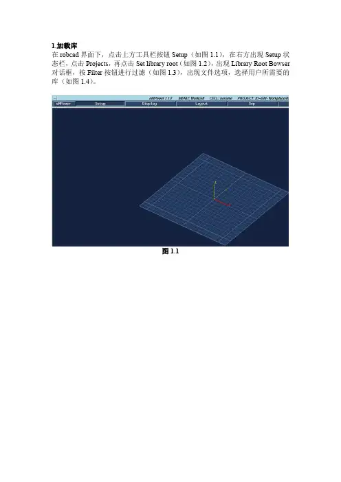
1.加载库在robcad界面下,点击上方工具栏按钮Setup(如图1.1),在右方出现Setup状态栏,点击Projects,再点击Set library root(如图1.2),出现Library Root Bowser 对话框,按Filter按钮进行过滤(如图1.3),出现文件选项,选择用户所需要的库(如图1.4)。
图1.1图1.2图1.3图1.42.加载车模在robcad界面下,点击上方工具栏按钮eMpower,出现下拉菜单选择Workcell (如图2.1)或者点击工具栏中按钮Layout(如图2.2),在右方出现Layout状态栏,点击Load cell(如图2.3),出现Load Cell对话框,选择用户所需要的车模(如图2.4)。
注:有时Cells框中无选项出现,按Thumbnails。
,出现选择对话框,选择用户所需要的车模(如图2.5)。
图2.1图2.2图2.3.图2.4图2.53.在画面中加入机器人在robcad界面下,点击上方工具栏按钮Layout(如图3.1),在右方出现Layou 状态栏,点击Get component(如图3.2),出现Get Component对话框,选择Libraries,选择用户所需要的机器人,Locate At:选择机器人位置,Instance Name:输入机器人名字(如图3.3)。
点击Locate At后的Position,出现Position对话框,点击Values,输入机器人所在位置的数据(如图3.4)。
图3.1图3.2图3.3图3.44.画面操作在robcad界面下,滚动鼠标中键滚轴拉远近视距,按住鼠标右键拖动进行画面的平移,同时按住鼠标中键+右键拖动进行画面的翻转。
5.控制机器人的运动在robcad界面下,点击上方工具栏中按钮eMpower,出现下拉菜单选择Workcell (如图5.1),在右下方出现工具框,选择Motion按钮(如图5.2),出现Motion 对话框(如图5.3),可按不同的坐标对机器人进行运动控制,点击Active mech,出现Mechanisms对话框(如图5.4),可选择机器人,点击编号或直接从界面中选择机器人。
第六章:其他选择主题描述eM-Workplace中的其他重要主题(如CAD集成)将在本章中进行介绍。
本章涵盖的主题。
使用eM-Workplace进行CAD集成简介。
I-DEAS与eM-Workplace集成。
用于CAD界面的独立GUI(翻译)。
数据菜单CAD翻译。
纹理映射。
更多数据命令Windows第1课:CAD集成(CI)能够链接到CADDS5,UG,Pro-E,I-DEAS和CATIA零件CAD集成(CI)是将其他CAD系统的数据导入eM-Workplace的更简洁的方式。
这是因为原来的CAD模型从来没有被翻译成eM-Workplace。
使用CI,将原始CAD模型作为组件读取并显示在eM-Workplace中。
与转换的组件不同,集成组件只是原始CAD数据的阴影。
因此,这个组件的“几何形状”是不能改变的,但是可以添加运动学。
什么是CAD集成答案?- 继续与产品数据相关联- CAD独立的电子制造环境- 访问产品组装树- 多个CAD系统环境- 沟通过程信息反馈- 通知设计问题- 初步设计链接- 快速准确地访问产品数据CAD集成优势- 使用“一流的”CAD和电子制造解决方案- 启用并行工程- 如按需设计审查- 尽早开始流程研究- 没有数据翻译或重复- 降低数据管理成本- 没有精确的损失- 属性,几何和装配链接CAD集成优势摘要- 提供快速和准确的程序- 允许并行工程- 降低数据管理成本EDS UG CI状态平台: HP / SGI / SUN应用:SPOT,DYNAMO,MAN,DRILL,CMM,FIXTURES,LINEUG版本:11,13, 15Dasault CATIA CI状态平台:IBM / HP / SUN / SGI应用:SPOT,DYNAMO,MAN,DRILL,CMM,FIXTURES,LINECATIA版本:4.1.6 - 4.2.0(PTC)CV CADDS CI状态平台:HP / SGI / SUN应用:SPOT,DYNAMO,MAN,DRILL,CMM,FIXTURES,LINE CADDS版本:6,7,8,9SDRC I-DEAS CI状态平台:HP / SGI / SUN / IBM应用:SPOT,DYNAMO,MAN,DRILL,FIXTURES,LINEI-DEAS版本:MS6,MS6a,MS7参数技术PRO-E CI状态平台:HP / SGI / SUN应用:SPOT ,DYNAMO ,MAN ,DRILL ,CMM ,FIXTURES ,LINEPRO-E 版本:18,19,20,2000i工业过程 CAD 集成的概念1基于同步数学的制造业 Level of Computeriz ation, CAEFactory eManufacturing Tools AutomationProduc tion Production Production Desi gn Engineerin gCAD 集成的概念2 CAD SystemEnviron ment Math Data and AtributesRO BCAD Envi ronmentConcurrent Access基于同步数学的制造业CAD 集成与 CAD 翻译的区别CAD 翻译(CAD 界面) +/-可以修改翻译的部分 + 需要较少的CAD 许可证 for Several CAD Sys tems in One CellEDS UG Dasault CATIAROBCAD Environm entCV CADDS5 SDRC I−DEAS- 打破了CAD模型和eM-Workplace模型之间的联系- 可能无法获得CAD模型的100%- 占用比CAD集成更多的磁盘空间CAD集成(CAD链接)+ / - 只读部分- 需要更多的CAD许可证+ 维护CAD模型和eM-Workplace +之间的“实时”链接查看在CAD 系统中查看CAD模型的100%+使用大约60%的磁盘空间(不重复数据)同一单元中的多个CAD集成部件用户现在可以将CADDS5,UG和CATIA,I-DEAS和Pro-E的CAD集成零件放在同一个单元中。
第4章:处理描述现在,我们将利用前三章所获得的知识来设置自己的路径,并使用eM-Workplace 库结构。
本章涵盖的主题· 逆向运动学:eM-Workplace的核心技术。
使用路径。
填充库。
从最少约束到最多约束第1课:逆运动学:e M-Workplace的核心技术原则定义机构/设备具有运动学的组件eM-Workplace Robot 在 运动链的末端创建一个TOOLFRAME 并编译(定义)该机制将使一个简单的运动学设备安装到eM-Workplace 机器人(或CMM )中。
放置编辑器“放”命令放在“源”的方向:将一个对象从源帧放到目标帧。
- >将对象从源框架移动到目标框架 - >对象的方向不受影响(保持源框架的方向) 以“目标”为导向:将一个对象从源框架到目标框架。
- >将对象从源框架移动到目标框架。
- >对象的方向改变为目标框架 Joint Angles Direct Kinematics Position and orientation of theend−effectorInverse KinematicsLink ParamtersLink ParamtersJoint Angles INPUTINPUTOUTPUT直接运动学直接运动学如何工作:1. 给eM-Workplace 一个状态/姿势。
状态/姿态包含机构的每个关节的确切值。
当前位置的 目标姿势J1 = 0 J1 = 10J2 = 10 移动到姿势J2 = 120J3 = 0 J 3 = 100J4 = 15 J4 = 45J5 = 40 J5 = 32J6 = 20 J6 = 462. eM-Workplace 将机制从当前位置移动到目标位置- 易于使用eM-Workplace ,因为eM-Workplace 已经知道联合价值- 直接运动学可用于任何运动装置,如枪支,夹具,机器人等。
逆运动学逆向运动学如何工作:1. 给eM-Workplace 一个位置。


Table of ContentsChapter 1. Introduction to eM-Workplace1.1Basics of Robcad operation 1.2View Control in e-M Workplace 1.3Entity and component conceptChapter 2. Modeling2.1 Setup World2.2 Display tool 2.3 Files2.4 Modeling Basics2.5 Opening and editing of direct models in rob cadChapter 3. Fundamentals of Kinematics3.1 Assigning Kinematics 3.2 Creating Devices3.3 Reading the States Command 3.4 DataChapter 4. Processing4.1 Creation of Library and project,4.2 Project and library setting.4.3 Placement of Robots and tools ( Work cell buildup)4.4 Tool V alidation (Static Collision)4.5 Auto placeChapter 5. Paths generations5.1 Creation of locations5.2 Robot path Creation. (Path editor)5.3 Attribute Assignment 5.4 Robot motions setting 5.5 Tcp settingChapter 6. Simulation6.1 Simulation of motion function: Move Commands 6.2 Path Finalizing and Dynamic collision detection 6.3 Interference checkingChapter 7. eM–Spot Worldw.d oc u -t r a c k.cwo7.1 Generation of weld location7.2 Different options to create weld location 7.3 Creation of weld tcp and remote tcp 7.4 Weld path editor 7.5 Spot setupChapter 8. eM OLP.8.1 Olp editor8.2 assigning attributes and different aux data 8.3 Assigning a simple sequence of operationChapter 9. Other applications9.1 Layer Menu 9.2 Tree Menu 9.3 Mc Rose9.4 View Manager 9.5 Note Editor 9.6 Report Creator 9.7 Program Editorw.d oc u -t r a c k.cwoChapter 1. Introduction to eM-Workplace :The eM-Workplace Workcell product enables the user to arrange graphically the components in a robotic workcell, and to verify the feasibility of the arrangement by simulating the operations which these components are intended to perform in the actual workcell. The user can customize the working environment individually for each robot controller with which the eM-Workplace system is intended to function. In addition, optional, special-purpose applications supplied with the eM-Workplace workstation, are utilized from within Workcell.Workcell facilitates designing a workcell by enabling the user to:Position and orient components in the workcell.Duplicate components.Attach components to each other.Write task files for use in simulations.Execute task files by means of an interpreter, without first compiling them.Move mechanisms or individual joints by motion commands and panels.To verify both the workcell and its tasks, Workcell notifies of:Violations of the limits of joint movements.Violations of speed and acceleration limits.Collisions and near misses.1.1 Basics of Robcad operationRobcad is a simulation software from which we can Create devices, assign kinematics, path creation and design validation, writing program to the robot etc. And mainly used to atomize the manufacturing industry .The basic Robcad window is a GUI, Looks as shown below.This is a main Menu Bar containing eMpower, Setup, Display etc.The above menu bar shows us the version of the Software ,work cell menu,cell name,project rootdirectory and pick instance.1.2: Layout:This is the Main menu of the workcell mode of the Robcad, from these options we can build up the workcell as per the given standard layout. And also this commands which arrange a station or workcell. These commands bring components to the workcell and change their placements. They permit storing modified workcells in the database as desired.The store command is deactivated until load cell is issued to load a workcell.The cell description window allows users to enter textual identifying descriptions for cells, and manually generate a cell preview. By using these options to create a text description and graphic thumbnail, users can then more accurately and quickly identify cells for loading, by viewing the description, graphic preview or using the Thumbnails option to view multiple cells in the directory.1.2.1:Load Cell:Mainly to load ie. to open the cell this option is used. The dialog displays an icon cell preview, if one was created, to enable accurate selection of the desired workcell. The Thumbnails options allows displaying thumbnail graphic previews of all cells in the directory, if previews were created.After selecting a cell, loads and displays a workcell in the database, replacing any previously displayed workcell. Beginning an eM-Workplace operating session opens a new workcell named noname. This command enables replacing that workcell with a specified workcell. If the workcell contains a single robot, that robot is selected as the active mechanism; its parameters appear in the data window. The workcell is loaded with its working frame situated at the origin of the graphics space.1.2.2:Get Cell:This option is used to Merge the no of cells and to make one big cell Merges a workcell with the displayed workcell. Brings to the graphics display the contents of a workcell in the database, constituting it as a group within the currently displayed workcell. The location of the merged workcell is specified as described for the create frame command, and a name for the merged workcell can be specified. This command is intended especially to merge with the existing workcell a component or group of another workcell that had been stored by means of the store as command. Selecting this command displays a browser window for finding the workcell directory: the window displays directories in the left scrollable region,and workcells in the right scrollable region. But the workcell must be located in the currentdirectory: the left scrollable region is deactivatedw.d oc u -t r a c k.cwo1.2.3:Get Component:It is the most commonly used option by which we can retrivethe component from the prescribed library to buildup the work cell.Which Brings from the database a specified component model, and locates it as describedfor the create frame command.w.d oc u -t r a c k.cwoSelecting get component displays a browser window for finding and locating the component:the window displays components in the right scrollable region. Selecting current project displays directories in the left scrollable region, but that region is deactivated to require that the component be taken from the current project. If libraries is selected, the left scrollable region displays libraries : special directories located under the root library directory the name of which the $LIB_ROOT environment variable holds. Each library contains components which many workcells can include, without the need to duplicate the components for each workcell. Any library may be selected: the left scrollable region is activated.1.2.4:Robot Envolope:Generates the work envelope of a robot.Generates and displays the work envelope of a specified robot, as an entity pertaining to the robot. This command produces the work envelope by using only joints 1, 2 and 3 to move the robot TOOLFRAME, where joint 1 is the joint attached to the base link; the base link is the link whose frame has been constituted as the BASEFRAME. The movement ofthese joints remains within their limits. A work envelope is illustrated below.w.d oc u -t r a c k.cwoThe robot must meet five criteria:1.The robot is articulated , having only rotational joints without any prismatic joint.2.The axes of joints 2 and 3 are parallel.3.The axis of joint 1 is perpendicular to the axes of joints 2 and 3.4.The axis of joint 1 lies on the extension of the plane that the TOOLFRAME describes when it is moved by varying only joints 2 and 3.5.The robot does not have “overhead” reach capability, i.e., the limits for joints 2 and 3render the robot incapable of bringing the TOOLFRAME to intersect the extended axis of joint 1.The work envelope is shown in light shading, but its display can be changed like that of any other entity. Except for modifying its display, however, other eM-Workplace commands do not affect the work envelope.The precision of the work envelope depends on a specified tolerance ; a specified clearance permits increasing the size of the computed envelope beyond the actual, maximum reach of the robot. If the system is unable to produce the work envelope itself, it generates and displays a closed curve showing the outline of the work envelope. This curve can be modified by eM-Workplace commands applicable to curves.Apart from these some of the other commands which are used to edit or create the entities in the workcells, which are like delete, create frame,working frame Group and ungroup and attach, detach.1.3:Setup:c ommands that define units and other parameters needed for variouseM-Workplacecommands.Color: Determines the color of eM-Workplace items. Selecting the command displays a color editing window listing the command parameters and showing four color bars. The three leftmost bars determine the values of the red, green and blue components in the resultant color. The numerical value corresponding to the height of each bar is displayed below the bar; the range is 0–255. The rightmost bar shows the resultant color. To modify the color of a eM-Workplacew.d oc u -t r a c k.cwoConfiguration:This is a very important command used in robcad, that facilitate setting many parameters for eM-Workplace workcells and applications. They permit storing the parameters in the database and then applying them to any workcell as desired. The parameters enable presetting most of the commands in the Setup menu, many of the commands in the Display menu, and other parameters. The values are assigned automatically by issuing corresponding eM-Workplace commands, and then by issuing the Configuration/store command.The configuration parameters are stored in a special robcad_config.xml file. When a workcell is loaded, the system searches for a file by that name in five locations, in the order as listed below,and presets the configuration parameters according to the contents of the first file it encounters:1.working_directory/robcad_config_<userLoginName>.xml.2.working_directory /robcad_config.xml. This file permits preparing custom configurations to meet the exigencies of a specific application. To produce this file, prepare a $HOME/robcad_config.xml file as described for 2, below, and then copy it to the working directory by means of the copy command in the Data/File Utilities submenu.3.$HOME/robcad_config.xml, where $HOME represents the home directory of the current user.This file permits each user to prepare a configuration file to meet specific needs or to express personal preferences. To produce this file, prepare the configuration as desired, and issue the store command with the user parameter.4./usr/local/robcad/usr/robcad_config.xml. This file enables establishing a standard for all users of the eM-Workplace workstation. To produce this file, first prepare a $HOME/robcad_config.xml file as described for 2, above, and then copy it to the /usr/local/robcad/usr directory by means of the copy command in the Data/File Utilities submenu.5.$ROOT/dat/robcad_config.xml, where $ROOT is the eM-Workplace installation directory:the default installation directory is /usr/local/robcad. This file is the default supplied with the eM-Workplace system;it should not be modified .In addition to the five robcad_config.xml files listed above, a file having any desired name with a .xml suffix can be placed in the $HOME/ROBCAD directory; the load command can then use this file to modify the configuration of the current workcell as desired. The store command produces both this file and also the file described in 2, above.If the Cell View/store command under the Viewing header in the Display menu has been invoked for a particular workcell, it overrides corresponding configuration parameters.Hot Key viewer:All possible user hot key combinations are organized and displayed in a ers may configure hot key combinations to match those they commonly use in their preferred CAD systems (e.g., display all =Ctrl+A ). The setup file robcad.hotkeys contains the default settings and is stored in the /$ROBCAD/dat directory. Users may not modify hot key shortcuts that use function keys, or that enable viewing controlled by the mouse or keyboard (e.g.,Ctrl+Arrow up for zooming in). The setup file is loaded together with eM-Workplace only once, preventing users from editing the values during a working session in a similar way to the loading of the .robcad file.w.d oc u -t r a c k.cwoThe following table lists the hot key combinations that users can customize:Operation description Blank paths Shift p Blank locations Shift l Blank local locations Shift x Blank global locations Sh Blank local paths Shift v Blank global paths Shift b Toggle display Ctrl a Display all Ctrl t Display paths Ctrl p Display locations Ctrl l Display local locations Ct Display global locations Ctrl gDisplay local paths Ctrl v Display global paths Ctrl b Open Setup menu Alt s Open Display menu Alt d Open Layout menu Alt l Open Sop menu Alt o Open Query menu Alt q Open Data menu Alt a Save cellCtrl s Status window menubar Ctrl mStatus window update Ct Undo Ctrl u w CenterAlt vw.d oc u -t r a c k.cwoThe following table lists the hot key combinations that may not be modified:Operation description Shortcut Graphic window local setup F5Graphic window display mode F10Graphic window full view F3Graphic window global setup F6Graphic window pick intent F11Graphic window pick level F12Keyboard viewing zoom in Alt arrow up Keyboard viewing zoom out Alt arrow down Keyboard viewing pan up Shift arrow up Keyboard viewing pan down Shift arrow down Keyboard viewing pan left Shift arrow left Keyboard viewing pan right Shift arrow right Keyboard viewing rotate up Arrow up Keyboard viewing rotate down Ar Keyboard viewing rotate left Arrow left Keyboard viewing rotate right Arrow rightMouse viewing zoom in Middle button drag left Mouse viewing zoom outMiddle button drag rightMouse viewing zoom window in CtMouse viewing zoom window out Shift&Alt left button Mouse viewing pan Right buttonRotate around viewcenter Middle&right buttons Rotate around viewpoint Ctrl middle&right buttons Online help F1 / Help (on Sun)UI form copy list F7UI form paste list Shift F7 / F8UI form okF9Window output menuF4Apart from these some simple commands are floor, motion, project and units.w.d oc u -t r a c k.cwo1.4:Display:This command is same for all the pages. Mainly used to change thedisplay property of the cell and the entities.And which affect in various ways the display in the graphics windows. If more than one graphics window is open, these commands affect allof them.w.d oc u -t r a c k.cwo1.6:DATA: MENU of submenus containing commands that enhance the flexibility of the eM-Workplace system by providing a means for displaying and manipulating data in the database.The eM-Workplace system uses data comprising workcells, components, and various files not included as part of the workcells and components. A workcell is constituted as a directory containing the various data files needed to describe the workcell; its name has a .ce suffix. A component is similarly constituted as a directory containing the various data files needed to describe the component; its name has a .co suffix. A directory containing workcell and component directories, together with task, connection, simulation and other files as needed for a complete eM-Workplace work session, is designated a project .w.d oc u -t r a c k.cwoThe pack and go is utilized toseparate the cell and its respective library from the main library. And other options are like cad import and cad export and project,& library utilities.Views Control in eM-Workplace.(Mouse Right click Menus.)Chapter: 2 Modeling And Kinematics:In order to use the eM-Workplace system to simulate a workcell, or car-parts station, the workcell must be equipped with components either supplied with eM-Workplace or designed by the user. One example of a component is a fixture unit , a mechanical system that uses force to hold two car parts together. Its objective is to remove all degrees of freedom before welding occurs, and to ensure that movement does not occur during welding.It must be designed to avoid collision with adjacent units and with the welding gun, and to minimize the cost of manufacture. The eM-Fixtures product constitutes components as fixture units.The eM-Workplace Modeling and eM-Fixtures products enable designing units as well as all of the other components that a station may require, and also facilitates modifying existing designs. The components can range from simple production workpieces to functioning mechanisms.Units can be modeled either individually or as part of a station; if the latter, the stationremains displayed as desired throughout the use of the Modeling and eM-Fixtures products.The component being modeled is always an instance of the component prototype that occurs in the database as a directory with a .co suffix appended to its name. A station can contain one or more instances of a component prototype; the component being modeled can be one of these instances, or it can be an instance of an existing component not present in the station, or it can be an instance of a new component.The Modeling and eM-Fixtures products utilize advanced CAD techniques for three basic operations:1.Constructing primitive and composite bodies.2.Producing mechanisms, i.e., kinematic components.3.Utilizing viewing and placement functions.Solid bodies are constructed in four different ways:üSweeping or revolving surfaces into solid entities.üGenerating 3D primitive bodies.üCombining 3D primitive bodies by means of Boolean operations.üCombining 3D primitive bodies by means of assembly operations.üDesigning a mechanism includes defining its joints, specifying for each joint:The type of the joint:rotational or prismatic (linear).The parent (controlling)link and the child (controlled)link .The position and orientation of the axis of each joint.The limits of the motion, speed and acceleration of each joint.Whether or not motion depends on other joints.If the joint is part of a closed loop constituting a four-bar linkage.Apart from this we can also directly open the modeled component and modify etc.w.d oc u -t r a c k.cwo2.1: Files:This initiate, conclude, and otherwise affect the current modeling session. Ifthe open command has initiated a modeling session for a component, the load cell command is deactivated . To activate the load cell command, issue close to terminate the modeling session.Load Cell: Loads and displays a workcell in the database, replacing any previously displayed workcell. Beginning a Modeling operating session opens a new workcell named noname. This command enables replacing that workcell with a specified new or existing workcell.Open: Brings a component to the display and initiates a modeling session.Initiates a modeling session for a component, and loads an instance of a component prototype. The instance can be selected from a component instance present in the currently displayed workcell, or it can be an instance of an existing component prototype, or it can be an instance of a new component that does not yet occur in the database as a prototype. The component instance can be edited either independently or as part of a currently displayed workcell. If it is a new component instance being edited as part of a workcell, its location in the workcell can be specified as described for the create frame command in the Workcell Layout menu. If it is edited independently, the workcell is unloaded.Close: Terminates a modeling session with a component. If the component loaded by the open command has been modified by means of Toolbox commands, either its prototype in the database can be updated accordingly, the same as issuing the save command, or thechanges can be discarded.w.d oc u -t r a c k.cwoGet Subcomponent:Brings from the database a specified component model, andlocates it as described for the Workcell Layout/create frame command. The component is constituted as a subcomponent of the component being modeled.Current Library: Specifies the current library for the component. and used to load the component from the appended library. Specifies either a library or the working directory (“current project”) for use during the current operating session. A library is a special directory located within the library root directory: either the default /usr/Robcad/LIBRARIES directory, or another directory as specified by the Setup/Projects/set library root command.Save as New Component:By this option the entity of a component can be saved separately in a different name. Constitutes as an eM-Workplace prototype component a list of specified entities in the graphics space. The component that results from the operation is placed in the current project, and is independent of the root component (unit) being modeled.The origin frame of the new component is superimposed on the working frame.Apart form these some of the direct modeling tools are explained and shown in tool bar manager.2.2: Features:PIPES: This will generate and edit various and sundry pipes . To generate a pipe, specify first the name of a new or existing pipe, then the cross section of the pipe, and finally the curve that determines the run of the pipe. Duly specifying these parameters activates the accept item; the successfully produced pipe is displayed both in the main graphics window and also in a separate graphics window that opens to display exclusively the pipe.BEAM: This will create beams . To generate a beam, specify first the name of a new or existing beam, and then the cross-sectional profile that is swept to produce the beam.Finally specify either the starting and end points, or else the starting point and the direction and length, to determine the direction and distance to sweep the profile: unlike pipes, beams are always straight. Duly specifying these parameters activates the accept item; selectingaccept generates the beam and displays it in the main graphics window.This menu containing three submenus. The Pipes submenu contains commands for producing various kinds of pipes; the commands in the Beams submenu create beams; the commands in the NC Blocks submenu produce various kinds of numerical-control (NC) blocks.w.d oc u -t r a c k.cwoNCBLOCKS: create and evaluate NC block s . NC blocks are the only parts of a unit that contact the car-part surface; they are positioned at the end of clamps. To prevent possible damage to the car part, the NC blocks should conform to the shape of the car-part surface.To ensure the accuracy of the contact surface of the NC blocks,numerical control (NC)machines fabricate them. Three numerical-control machine manufacturing processes areused to fabricate NC blocks: Five-Axis Milling, Three-Axis Milling, and Electric-Discharge Machine (EDM). eM-Workplace currently supports only Five-Axis Milling and EDM. The Five-Axis Milling process fabricates the NC block by cutting its contact surface in three dimensions. This process is used when the NC block is generated by means of the NC Block/cut command. The EDM process fabricates the NC block by cutting its contact surface in “two and a half”dimensions: a 2D contour is swept along the normal to its plane to produce a 3D NC block. This process is used when the NC block is generated by using the NC Block/sweep or ruled nc block command. It is a less expensive process than Five-Axis Milling, and can be used when the car-part shape varies only in the two dimensions of the contour.Before creating an NC block, perform two steps from within eM-Line:1.Issue the read or assign option of the eM-Line Prepare/Import/PLPs command to create a PLP on the car part at the desired clamping location for each NC block to be created. Assign to the PLPs a function of clamping or resting.w.d oc u -t r a c k.cwow.d o cu-t r a c k.cw o2.3: Tool Box Manager:It is Combination of all tools which includes 2-D,3-D and Surface editing tools.PANEL of icons (toolboxes) that represent commands and submenus, located at the lower-right corner of the eM-Workplace display. This document describes only the toolboxes that constitute part of the Modeling product. The remaining toolboxes are separate applications and are described separately.2.3.1General tool:123 4 5 6This tool is divided in to threesection like EDIT,FRAME andGROUPS, that edit in various waysa unit, component or other entity;that generate frames, move theworking frame, and displayself-origin frames; and create andedit groups and assembliesw.d o cu-t r a ck.cw o2.3.2: 2-D Sketcher:If solid creation specifies polyhedral approximation, these solids are represented as polyhedral approximations with a specified number of sides.These commands can be used with a 2D graphics window as opened by the 2D Window/open command, in order to produce a umerical-control (NC)block for holding a workpiece. The modifications can be effected, however, either in the 2D graphics window or in the main graphics window; the results appear simultaneously in both windows.2.3.3: 3-D Sketcher:This is a command by which we can generate and edit solidentities in the graphics space. They generate various solid primitives, and combine these primitives by means of three Boolean operations. The solid creation command specifies whether the system generates solids that are represented exactly, or as polyhedrons with a specified polyhedral approximation: it specifies the number of sides for the approximation.We can also create the primitive objects like cube, box, wedge, cylinder, cone, sphere, torus and ring commands each generates a solid either with its frame superimposed on a specified frame , or such that the origin of its frame is placed on a point and its Z axis is parallel to a line, with the other two axes of its frame having an arbitrary orientation. The frame can be specified by selecting any individual frame, or by selecting an entity for which to use its frame, or it by picking anywhere in the graphics space. The last option places the origin of the frame of the solid at the projection of the picked point onto the working plane, the X-Y plane of the working frame; and orients the frame parallel to the working frame. The Subtool is shown below.This is a special 2-D tool used to create may geometrical features in the modeling world.The created geometries are used either in the 3-D operation or in the kinematics. And these are the simple 2-d tool options which are created same as in the other engineering tools like Auto cad, CA TIA etc. which generate and edit entities in the graphics space. These entities have fewer than three dimensions; they include points, lines, polylines, arcs, circles,and curves. The Edit commands produce polylines from curves and polygons from polylines; the sweep commands produce solids from curves. If the solid creation command in the 3D Sketcher submenu specifies exact, the solids are exact representations.w.d oc u -t r a c k.cwo3-D Sketcher.2.3.4: Surface:which generate and edit surfaces in the graphics space. All of thesesurfaces are true surfaces, but no planar surfaces are displayed as faceted.The frame of the surface that the revolution, ruled through curves, surface by border, sweep along direction and offset surface commands produce, is superimposed on the origin frame of the component being modeled. The frame of the surfaces that the rectangle by diagonal,polygon, polygon by points, and polygon from curve commands produce, is located at the center of the surface with the Z axis normal to the surface and the X axis pointing to a system-determined first vertex .2.3.5: Query:This command is used to know the information of the component,measurethe entity,and to know the unit etc,,like wise to enquire regarding the entity mainly this command is applicable.And the Placement editor is extensively used to move place or put and many moreoptions, is explained seperatly in the other chapterw.d oc u -t r a c k.cwo。
Pattern Design 8.0Professional Edition目录第一章系统认识---------------------------------------------------------------------------7 1-1 软件安装7 1-2 软件卸载9 1-3 开机步骤11 1-4 关机步骤11 1-5 认识Gerber LauchPad 12 1-6 输入输出PDS用户设置14第二章放码及读图----------------------------------------------------------------------- 15 2-1尺码放缩152-2-1 如何在AccuMark系统中进行放缩15 2-2-2 样片放缩范例152-2-3 衬衫前片放缩分析16 2-2 放缩表17 2-2-1建立放缩表17 2-2-2 放缩规则182-2-3 放缩方式19 2-3 剪口参数表20 2-4 读图21 2-4-1 读图工具212-4-2 读图前的样片准备23 样片记录表24放缩记录表25 2-5 读图步骤26 2-6 核对样片30 2-6-1 通过AccuMark资源管理核对样片30 2-6-2 通过PDS核对样片31 2-7 修改读图资料32 2-8 点的属性35 2-9 读图状况与排除36 2-10读取特殊的样片372-10-1 读入多条布纹线372-10-2 读入圆形内部线382-10-3 读入定位分割线382-10-4 读入大片392-10-5 读网状图(直接读取尺码)41第三章排版资料及产生排版图-------------------------------------------------------- 42 3-1 产生排版图的流程42 3-2 排版档案43 3-2-1 注解档案433-2-2 排版放置限制档案453-2-3 款式档案473-2-4 版边版距档案493-2-5 排版规范档案503-2-6 活动讯息记录533-2-7 产生排版图53第四章排版系统------------------------------------------------------------------------54 4-1 排版界面54 4-2 排版图资料54 4-3 工具盒55 4-4 键盘功能62 4-5 菜单功能63 4-6 自定义工具列76 4-7 自动排版76 第五章绘图与裁割-----------------------------------------------------------------------79 5-1 绘图参数表79 5-2 绘图81 5-3 绘图相关设定835-3-1 如何设定绘图机835-3-2 如何设定媒介86 5-4 绘图管理87 5-5 产生绘图档案(*.GEN或*.PLT)88 5-6 Winplot输出绘图档案89 5-7 执行裁割文件905-7-1 执行裁割文件参数表905-7-2 产生裁割资料94第六章Accumark资源管理器---------------------------------------------------------- 99 6-1 储存区99 6-2 资料管理100 6-3 文件的汇入与汇出101 6-4 备份资料102 第七章对花对格----------------------------------------------------------------------------106 7-1 对花对格原理106 7-2 对花对格设定109 7-3 对花对格相关内容113 7-4 利用内部线和标记设定对花对格114第八章变更和尺码代号-------------------------------------------------------------------115 8-1 变更的工作流程115 8-2 变更种类116 8-3 样片分析1178-4 制作变更档案123 8-5 尺码代号124 8-6 单量单裁的排版规范设定126 8-7 产生变更样片127 8-8 绘制变更样片128第九章文件转换----------------------------------------------------------------------------129 9-1 AAMA文件转换129 9-2 Lectra文件转换136 9-3 DXF文件转换143第十章Accumark打版系统------------------------------------------------------------- 146 10-1 界面的认识146 10-2 菜单149 10-2-1 档案功能149 10-2-2 编辑功能154 10-2-3 检视158 10-2-4 点的处理167 10-2-5 剪口181 10-2-6 线段处理186 10-2-7 样片处理205 10-2-8 放缩功能254 10-2-9 量度功能281 快捷键一览表286 第十一章打版实务-------------------------------------------------------------------------288 11-1 A字裙288 11-2 男直筒裤292 11-3 插肩袖茄克297培训大纲第一天:读图放码1.放缩记录表、样片记录表的填写2.将放缩记录表输入电脑中(放缩表编辑)3.读图(包括内部资料)4.提取、修改读图资料5.涉及资料管理、硬件设置、系统设置6.练习及测试第二天:资料编辑1.款式档案2.注解档案3.放置限制档案4.剪口5.版边版距档案6.对花对格档案7.排版规范档案8.产生排版图(执行排版规范)9.自动排版10.涉及资料管理、硬件设置、系统设置11.练习及测试第三天:排版、绘图1.排版系统(菜单、工具栏)2.绘图参数表(样片绘制参数表及排版图绘制参数表)3.绘图(绘制样片、绘制排版图)4.绘图机的操作5.涉及资料管理、硬件设置、系统设置6.练习及测试第四天:样片设计(PDS)1.档案2.编辑3.检视4.点的处理5.线段处理6.练习及测试第五天:样片设计(PDS)1.样片处理2.放缩3.量度4.练习及测试5.综合练习及常见问题讲解6.问题解答引言集团历史1968年,格柏科学有限公司成立其子公司格柏科技有限公司,为以耗时的手工劳动为特征的劳动密集型工业开发自动化产品,预示着全球纺织品制造业将迎来一个新时代。