离型涂布方式
- 格式:pdf
- 大小:286.27 KB
- 文档页数:10
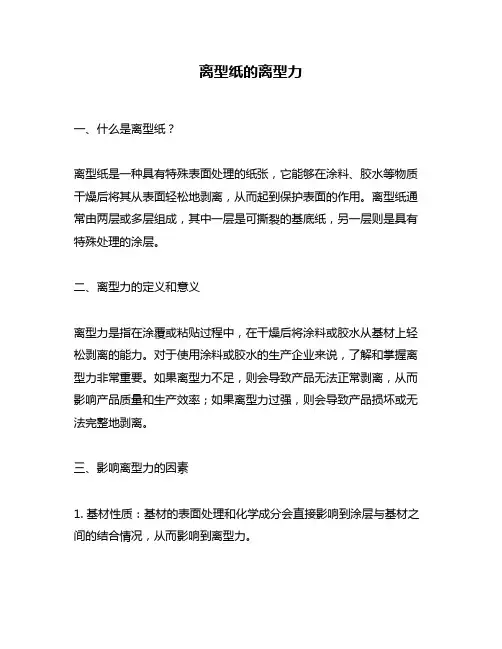
离型纸的离型力一、什么是离型纸?离型纸是一种具有特殊表面处理的纸张,它能够在涂料、胶水等物质干燥后将其从表面轻松地剥离,从而起到保护表面的作用。
离型纸通常由两层或多层组成,其中一层是可撕裂的基底纸,另一层则是具有特殊处理的涂层。
二、离型力的定义和意义离型力是指在涂覆或粘贴过程中,在干燥后将涂料或胶水从基材上轻松剥离的能力。
对于使用涂料或胶水的生产企业来说,了解和掌握离型力非常重要。
如果离型力不足,则会导致产品无法正常剥离,从而影响产品质量和生产效率;如果离型力过强,则会导致产品损坏或无法完整地剥离。
三、影响离型力的因素1. 基材性质:基材的表面处理和化学成分会直接影响到涂层与基材之间的结合情况,从而影响到离型力。
2. 涂料或胶水性质:涂料或胶水的成分、浓度、粘度等性质会影响到其与基材的结合情况和干燥时间,从而影响到离型力。
3. 涂布方式和条件:涂布方式和条件包括涂布厚度、温度、湿度等因素,它们会影响到涂料或胶水的干燥速度和结构形态,从而影响到离型力。
4. 储存环境:储存环境中的温度、湿度等因素会直接影响到离型纸的性能,从而影响到离型力。
四、提高离型力的方法1. 优化涂层配方:通过调整涂料或胶水的成分和浓度,以及优化涂布方式和条件等方法来提高离型力。
2. 选择适合的基材:选择适合自己产品的基材,并对其进行表面处理,以提高涂层与基材之间的结合情况。
3. 控制储存环境:在储存离型纸时,控制好温度、湿度等因素,避免出现过高或过低的情况。
4. 加强质量管理:加强对生产过程中各项参数和指标的检测和监控,及时发现问题并进行调整,以提高离型力。
五、离型纸的应用领域离型纸广泛应用于电子、印刷、塑料、建材等行业中。
例如,在电子行业中,离型纸主要用于保护印刷电路板;在印刷行业中,离型纸主要用于保护印刷品表面;在塑料行业中,离型纸主要用于模具表面防粘剂。
六、总结离型力是影响离型纸性能的重要因素之一。
了解和掌握离型力对于生产企业来说非常重要。
氟素离型膜生产工艺
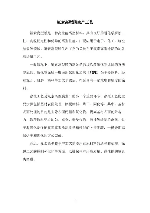
氟素离型膜是一种高性能离型材料,具有良好的耐化学腐蚀性、高温稳定性和优异的离型性能,广泛应用于电子、化工、航空航天等领域。
氟素离型膜生产工艺的关键在于氟素离型涂层的制备和涂覆工艺。
一般情况下,氟素离型膜的制备是通过涂覆氟化物涂层的方法完成的。
氟化物涂层一般采用聚四氟乙烯(PTFE)为主要原料,经过混合、研磨、稀释等工艺步骤后,得到具有一定浓度和粘度的涂料。
涂覆工艺是氟素离型膜生产的另一个重要环节。
涂覆工艺的主要步骤包括基材表面处理、涂覆涂料、烘干、固化等。
其中,基材表面处理的目的是去除表面污垢和氧化物,提高基材表面的附着力;涂覆涂料要求均匀、充分,避免气泡、流挂等缺陷的出现;烘干和固化是保证氟素离型涂层质量和性能的关键步骤,一般采用高温烘干和固化的方式完成。
总之,氟素离型膜生产工艺需要注意原材料的选择和处理、涂覆工艺的控制和优化等方面,以确保生产出高质量、高性能的氟素离型膜。
- 1 -。
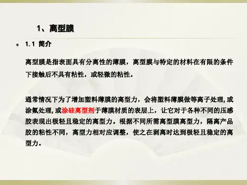
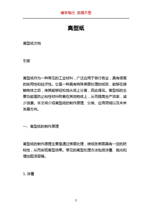
离型纸离型纸文档引言离型纸作为一种常见的工业材料,广泛应用于各行各业,具有很高的实用性和经济性。
它是一种具有特殊表面处理的纸张,能够在接触物体之后,使其能够轻松地从纸上分离,因此得名。
离型纸的主要功能是防止粘性材料附着在其他物体上,从而提高生产效率,减少浪费。
本文将介绍离型纸的制作原理、分类、应用领域以及未来发展方向。
一、离型纸的制作原理离型纸的制作原理主要是通过表面处理,使纸张表面具有一定的防粘性,从而实现离型效果。
常见的离型处理方法包括涂覆、抛光和增加阻滞层等。
1. 涂覆涂覆是一种常用的离型处理方法,通常使用聚合物涂料进行涂覆。
涂覆过程中,将聚合物涂料均匀地涂布在纸张表面,形成一层均匀的涂层。
这个涂层能够在接触物体的时候,形成一种隔离层,防止物体与纸张黏连在一起。
2. 抛光抛光是通过对纸张表面进行抛光处理,使其表面更加光滑,从而降低物体附着的可能性。
抛光处理通常使用抛光剂和抛光机械完成。
3. 增加阻滞层增加阻滞层是一种特殊的离型处理方法,通过在纸张表面加工一层阻滞层,使物体与纸张之间形成一层隔离层。
这种阻滞层可以是特殊的化学涂料或添加剂。
二、离型纸的分类离型纸可以根据其应用领域和制作材料进行分类。
根据应用领域,离型纸主要可以分为工业离型纸和食品级离型纸。
1. 工业离型纸工业离型纸主要应用于工业制造过程中,用于防止粘性材料黏附在设备、工具和模具上。
工业离型纸通常使用较粗的纸张和持久的涂层,以确保其在高温、高压和严苛的环境下具有良好的离型效果。
2. 食品级离型纸食品级离型纸主要应用于食品加工和包装行业,用于防止食物粘附在容器和包装材料上。
食品级离型纸通常采用无毒、无味的材料制作,以确保对食品的安全性。
根据制作材料,离型纸可以分为硅油离型纸、石墨离型纸和蜡离型纸等。
三、离型纸的应用领域离型纸在各行各业都有广泛的应用,下面将介绍离型纸在几个主要领域的应用情况。
1. 粘合剂制造离型纸在粘合剂制造过程中起到了重要的作用。
离型膜涂布工艺与关键指标介绍!离型膜涂布方式概述涂布方式大致分为:1、光辊涂布2、网纹涂布3、刮刀式涂布4、喷雾涂布和帘式涂布根据不同产品,涂料特性不同而采用不同涂布方式。
各涂布方式的特点(一)光辊涂布这种涂布采用两辊或多辊转移涂布方式,调整各辊之间的间隙和转速比列,就可以调整涂布量的大小。
整涂布头的结构比较复杂,要求上胶辊、涂布辊、牵引辊及刮刀的加工精度和装配精度要求较高,成本较高。
由于这种涂布机采用高精度光棍进行涂布上胶,涂布效果好,涂布量大小除了通过上胶辊和涂布辊之间的间隙来调整,还可以通过涂布刮刀微动调节来灵活控制,涂布精度高。
(二)网辊涂布这种涂布设备主要采用网纹(凹眼)涂布棍进行上胶,其涂不均匀性较好,而且涂布量准确,但缺点是涂布量难调节。
用网纹辊涂布时,涂不量与网纹辊的凹眼深度和胶水自身的特系(黏度、固含量)有关。
(三)刮刀式涂布刮刀式涂布往往回出现上胶不均匀,主要与刮刀的加工精度、刮刀安装方法涂布时刮到于背胶轮的角度以及涂料的黏度有很大关系。
刮刀的平整度精度要求高,就是指刮刀不翘曲变形或缺口,否则涂布量误差大。
在涂布时,刮刀与上胶轮的觫点切线间的角度一般在15o~30o之间,如果太大,其刮到几乎顶着背胶轮,背胶轮高速运转时刮刀容易引起震动,引起涂布不均匀,涂布量差异大。
另外,还会引起涂布的膜面不平整、有刮痕,同时还易引起刮刀刀刃损伤。
(四)喷雾涂布和帘式涂布喷雾涂布和帘式涂布新型涂布方式,预示着美好的发展前景。
上述的发展不可能一帆风顺,必须面临许多技术上的挑战。
高固含量刮刀涂布会产生诸如刮刀痕、刮刀压力大、刮刀上涂料析出(俗称翻料)和刮刀磨损快等运转性问题。
计量施胶压榨涂布涂布必须要面对高速、高固含量和高涂布量涂布所带来的诸多难题,包括涂布辊压区出口的雾溅、涂布面的橘皮纹纸病等。
新型涂布方式也要解决常规涂布中不曾遇到的新问题。
干燥工艺基础1、涂布和干燥的相互关系:干燥过程和涂面布过程各自独立,又相互联系:涂层的性质影响到干燥工艺的设计和操作;涂布速度,涂层的厚度决定干燥长度;干燥过程中涂层有流平过程,因此一台涂布机在设计过程中能否准确地运用最佳期的涂布、干燥工艺,平衡两者的关系,最终影响到涂布机的综合技术性能。
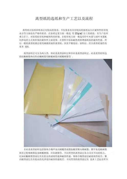
离型纸的选纸和生产工艺以及流程离型纸对原纸即纸基层有较高的要求,不仅要求其具有较高的强度而且在耐热性松厚度水分等方面也有严格的要求。
在原纸定量方面一般选用125g/m2以上的纸张,其生产技术难点在于,对原纸松厚度和耐热性的控制。
在松厚度方面一般选用针叶木浆与阔叶木浆配比抄造的方式来控制在耐热性方面需要,在浆料中添加耐热剂来增强纸张的耐热性能。
所以一般的离型纸都会使用淋膜纸制作离型纸,因其平整度好,韧性好,符合离型纸制作的基本要求。
离型涂料层可分为两大类,即硅系离型涂料层和非硅系离型涂料层。
硅系离型材料包括硅酮树脂和改性硅酮树脂用醇酸树脂丙烯酸树脂等。
非硅系离型材料包括铬络合物甲基丙烯酸型或脂肪酸型聚丙烯树脂,聚甲基戊烯树脂和其它特殊树脂氨基醇酸树脂,环氧树脂等。
不同类型的离型涂层各自具有不同的特点,比如硅酮树脂型涂层具有优良的剥离性能和耐热性能,铬络合物型涂层耐溶剂性较差,聚丙烯型涂层具有较高的光泽度但耐热性能较差。
不同类型的离型涂层其技术工艺也有所不同,硅系离型涂料一般采用辊式或刮刀式的涂布方法,且要求所用的原纸要先进行一层底涂。
底涂的主要目的是为了提高平滑度和抗硅系涂料渗透的能力。
聚丙烯树脂和聚甲基戊烯树脂型涂层主要通过挤压涂布的方式,它所用原纸可以不进行底涂,其涂层中的其它添加成分通过挤压涂布机的进料槽进料,这些离型涂层技术工艺都涉及到涂层剥离强度的控制,这也是其技术难点所在。
因为这又涉及到剥离力控制剂的选择及其对离型涂层其他性能的影响。
离型纸的生产工流程分为四大类:第一道工序:带有印刷的离型纸,淋膜纸,硅油纸必须先印刷,才能做后道工序:淋膜和涂硅。
第二道工序:P E淋膜(涂塑),PE淋膜机又称涂塑机,将热熔的PE塑料膜均匀地涂布在纸张表面,形成淋膜纸,也称涂塑纸或塑纸。
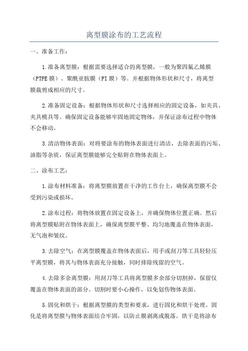
离型膜涂布的工艺流程一、准备工作:1.准备离型膜:根据需要选择适合的离型膜,一般为聚四氟乙烯膜(PTFE膜)、聚酰亚胺膜(PI膜)等。
并根据物体形状和尺寸,将离型膜裁剪成相应的尺寸。
2.准备固定设备:根据物体形状和尺寸选择相应的固定设备,如夹具、夹具模具等。
确保固定设备能够牢固地固定物体,并保证涂布过程中物体不会移动。
3.清洁物体表面:对将要涂布的物体表面进行清洁,去除表面的污垢、油脂等杂质,保证离型膜能够完全贴附在物体表面上。
二、涂布工艺:1.涂布材料准备:将离型膜放置在干净的工作台上,确保离型膜不会受到污染或损坏。
2.涂布过程:将物体放置在固定设备上,并确保物体位置正确。
然后将离型膜贴附在物体表面上,确保离型膜平整、均匀地覆盖在物体表面,无气泡和皱纹。
3.去除空气:在离型膜覆盖在物体表面后,用手或刮刀等工具轻轻压平离型膜,将其与物体表面充分接触,同时排除残留的空气。
4.去除多余离型膜:用刮刀等工具将离型膜多余部分切割掉,保留仅覆盖在物体表面的部分。
切割时要小心操作,以免划伤物体表面。
5.固化和烘干:根据离型膜的类型和要求,进行固化和烘干处理。
固化是将离型膜与物体表面结合牢固,以防止膜剥离或脱落。
烘干是将涂布后的物体放置在恒温烘箱或使用其他设备进行加热,加速涂布材料的固化和干燥。
三、检测和质量控制:1.视觉检测:对涂布后的物体进行视觉检测,检查离型膜是否平整、无气泡、无缺陷和污染等。
2.膜厚和附着力测试:使用膜厚计对涂布后的物体进行测试,确保膜厚符合要求;同时使用附着力测试仪对离型膜与物体表面的附着力进行测试,确保附着力达到标准。
3.包装和储存:对合格的涂布后物体进行包装,确保离型膜不受外界污染和损坏。
存放在干燥、阴凉的地方,避免日光直射,以延长离型膜的寿命。
以上就是离型膜涂布的工艺流程,涂布离型膜是一种常见且重要的工艺,能够有效地保护物体表面,提高物体的使用寿命和性能。
在实际操作中,还需根据具体情况做出调整,以确保涂布效果的质量和稳定性。
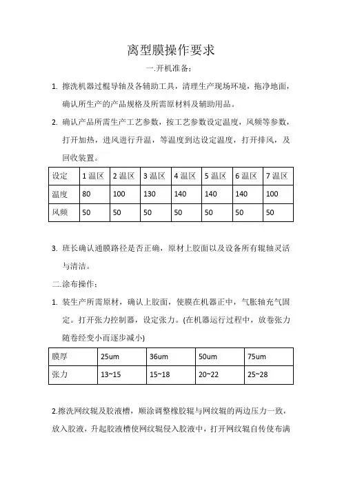
离型膜操作要求一.开机准备;1.擦洗机器过棍导轴及各辅助工具,清理生产现场环境,拖净地面,确认所生产的产品规格及所需原材料及辅助用品。
2.确认产品所需生产工艺参数,按工艺参数设定温度,风频等参数,打开加热,进风进行升温,等温度到达设定温度,打开排风,及回收装置。
3.班长确认通膜路径是否正确,原材上胶面以及设备所有辊轴灵活与清洁。
二.涂布操作;1.装生产所需原材,确认上胶面,使膜在机器正中,气胀轴充气固定。
打开张力控制器,设定张力。
(在机器运行过程中,放卷张力随卷经变小而逐步减小)2.擦洗网纹辊及胶液槽,顺涂调整橡胶辊与网纹辊的两边压力一致,放入胶液,升起胶液槽使网纹辊侵入胶液中,打开网纹辊自传使布满胶液,顺涂调整刮棒角度使刮棒与膜平行接触。
3.确认设备达到生产条件,开机按警铃通知收卷,等待对方回铃开机,先底速运行压下橡胶辊并用色笔在膜背面做上胶记号,观察膜面确认膜面上胶正常生速。
4.因离型硅油中溶剂易挥发,胶液桶要加盖好,胶液槽中胶液要少加勤添,不得有脱液,脱涂。
三.收卷操作;1.确认温度,风频等参数及生产所需辅助材料领用。
2.在收卷轴装产品所需宽幅管芯,气胀冲气。
确认通膜路径。
3.打开纠偏开关,在纠偏控制盒按下自动。
打开相应收卷轴张力,按收生产原材厚度设定相应张力。
(张力在开机过程中要根据卷经变大而逐步增加)。
4.听涂布开机铃声后,回铃按下相应收卷轴启动,打开相应张力开关和同步启动,升速由涂布人员升速,待到涂布上胶记号到达收卷处按下计米器归零。
5.用手电侧照膜面观察膜面有无划伤,次点,彩虹纹。
如有划伤要到涂布和烘箱确认查找。
要每500米观察一次膜面,记录一次工艺参数。
6.记录原材料货源记录,规格,填写产品记录。
四.包装操作;1.产品完成在机器上先用缠绕膜缠绕,再用泡棉包好缠绕膜缠绕。
2.用两块木板夹两块泡棉用打包带固定打包,放在托盘固定再用打包带固定后用缠绕膜缠绕。
贴上产品标签。
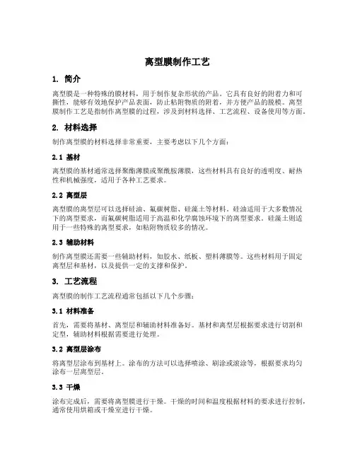
离型膜制作工艺1. 简介离型膜是一种特殊的膜材料,用于制作复杂形状的产品。
它具有良好的附着力和可撕性,能够有效地保护产品表面,防止粘附物质的附着,并方便产品的脱模。
离型膜制作工艺是指制作离型膜的过程,涉及到材料选择、工艺流程、设备使用等方面。
2. 材料选择制作离型膜的材料选择非常重要,主要考虑以下几个方面:2.1 基材离型膜的基材通常选择聚酯薄膜或聚酰胺薄膜,这些材料具有良好的透明度、耐热性和机械强度,适用于各种工艺要求。
2.2 离型层离型膜的离型层可以选择硅油、氟碳树脂、硅藻土等材料。
硅油适用于大多数情况下的离型要求,而氟碳树脂适用于高温和化学腐蚀环境下的离型要求。
硅藻土则适用于一些特殊的离型要求,如粘附物质较多的情况。
2.3 辅助材料制作离型膜还需要一些辅助材料,如胶水、纸板、塑料薄膜等。
这些材料用于固定离型层和基材,以及提供一定的支撑和保护。
3. 工艺流程离型膜的制作工艺流程通常包括以下几个步骤:3.1 材料准备首先,需要将基材、离型层和辅助材料准备好。
基材和离型层根据要求进行切割和定型,辅助材料根据需要进行处理。
3.2 离型层涂布将离型层涂布到基材上。
涂布的方法可以选择喷涂、刷涂或滚涂等,根据要求均匀涂布一层离型层。
3.3 干燥涂布完成后,需要将离型膜进行干燥。
干燥的时间和温度根据材料的要求进行控制,通常使用烘箱或干燥室进行干燥。
3.4 固定将干燥后的离型膜固定在产品表面。
可以使用胶水、纸板或塑料薄膜等材料进行固定,确保离型膜与产品表面贴合紧密。
3.5 压力处理对固定好的离型膜施加一定的压力,使其与产品表面更加紧密结合。
可以使用压力机、压力辊等设备进行压力处理。
3.6 脱模经过一定时间的压力处理后,离型膜与产品表面的粘附物质会被完全隔离,此时可以进行脱模。
脱模的过程需要小心操作,以免损坏产品表面。
4. 设备使用离型膜制作工艺中需要使用一些设备,主要包括:•切割机:用于将基材和离型层切割成所需形状和尺寸。
离型纸的正确使用方法
离型纸是一种常见的办公用品,它可以帮助我们在复印、打印、绘画等过程中,将图案或文字从纸上转移到其他材料上,起到保护原稿的作用。
但是,很多人在使用离型纸时并不是很熟练,容易出现一些问题。
下面,我们就来了解一下离型纸的正确使用方法。
选择合适的离型纸。
离型纸的种类很多,有单面涂布的、双面涂布的、透明的、不透明的等等。
我们需要根据自己的需要选择合适的离型纸。
比如,如果要复印或打印文字,可以选择透明的单面涂布离型纸;如果要绘画,可以选择不透明的双面涂布离型纸。
正确使用离型纸。
在使用离型纸时,我们需要将它放在原稿上面,然后用铅笔或者圆珠笔在离型纸上描绘出需要转移的图案或文字。
描绘时,要用适当的力度,不要过于用力,否则会损坏原稿。
描绘完成后,将离型纸翻转过来,将涂布面贴在需要转移的材料上,然后用铅笔或者其他硬笔头在离型纸上轻轻地涂抹,使图案或文字转移到材料上。
涂抹时,要注意力度,不要过于用力,否则会使图案或文字模糊不清。
注意保存离型纸。
使用完离型纸后,要将它保存在干燥、阴凉的地方,避免阳光直射或潮湿。
如果离型纸被弄湿了,可以用吹风机将其吹干,但要注意不要吹得太热,否则会使离型纸变形。
离型纸是一种非常实用的办公用品,正确使用它可以帮助我们更好
地完成工作。
希望大家在使用离型纸时,能够注意以上几点,避免出现不必要的问题。
离型膜都有哪些作法?
PET离型膜是热转印常用到的一种材料,底材是PET,经过涂布硅油而成所以也叫硅油膜。
常规厚度从12um至100um。
有冷热撕和光哑面之分,经过防静电和防划伤处理,产品具有很好的吸附性和贴合性。
PET离型膜:又称热转印膜、剥离膜、隔离膜、打滑膜、天那纸、硅油膜、防粘膜、硅油离型纸、硅油纸、掩孔膜、PET离型膜也叫PET转移膜,这种转移膜的特点是拉伸强度高,热稳定性好、热收缩率低,表面平整光洁、剥离性好,可多次反复使用。
它主要用做真空镀铝的载体,就是将PET膜置于真空镀铝机镀铝后,涂胶与纸复合,然后将PET膜剥离,铝分子层通过胶粘作用便转移到纸板表面上,形成所谓的镀铝卡纸。
镀铝卡纸的生产流程是:PET基膜→离型层→色层→镀铝层→涂胶层→转移到卡纸。
厚信PET离型膜性能:
1、没有迁移现象,消除了硅树脂离型膜转移到其所紧贴的材料上去的危险;
2、离型膜单面或双面涂层单位面积重量的允差非常小;
3、基膜具有优异的机械强度和化学性能;
4、在极端条件天气下有很高的稳定性,在较长时间内耐高温性可以达到130℃左右,在1个小时内可以达到180℃左右;
5、较长的保存限期;
6、背胶类离型PET以硅的移动性和加热后的剥离力的变化分为轻剥离型、中剥离型、重剥离性,并可根据要求控制离型力,耐热性能良好。
高岭土涂布离型纸流程1.引言高岭土涂布离型纸是一种常用的工业材料,用于各种涂布行业的生产和制造过程中。
本文将介绍高岭土涂布离型纸的流程和重要步骤。
2.材料准备在进行高岭土涂布离型纸的制作前,需要准备以下材料:-高岭土粉末-纤维素纸张-粘合剂-涂布机3.离型纸制作流程3.1准备工作首先,将高岭土粉末与粘合剂混合,在一个干燥的容器中搅拌均匀,确保高岭土与粘合剂充分融合。
3.2纤维素纸张处理将纤维素纸张剪裁成所需的尺寸,并进行预处理。
预处理包括清洁和烘干,以确保纸张表面干净无尘,并增强纸张的吸附性能。
3.3涂布过程-将纤维素纸张放置在涂布机上。
-使用涂布机将准备好的高岭土混合物均匀地涂布在纸张表面上。
涂布机确保涂料均匀分布,使得纸张上的高岭土层厚度一致。
-待涂布完成后,立即将涂布纸通过烘干设备进行干燥,以确保高岭土与纤维素纸张的牢固结合。
3.4加工处理经过涂布和干燥后的高岭土涂布离型纸需要进行一系列的加工处理,以增强其性能和质量。
-将涂布纸进行热压,以确保高岭土与纤维素纸张之间的结合更加牢固。
-定型处理:通过对高岭土涂布离型纸进行定型处理,以提高其耐热性和尺寸稳定性。
4.应用领域高岭土涂布离型纸在各种领域得到广泛应用,主要包括:-建筑材料领域:用于建筑隔热材料、地板等的制作。
-化工行业:用于涂料和胶粘剂的分离和保护。
-电子行业:用于电子产品的保护和隔离。
-包装行业:用于冷冻食品、糕点等的包装,并保持产品的新鲜度和质量。
5.结论高岭土涂布离型纸的制作流程包括准备工作、纤维素纸张处理、涂布过程和加工处理等步骤。
通过以上流程,可以制作出质量稳定、性能优良的高岭土涂布离型纸,在各个应用领域发挥重要作用。
希望本文对读者理解高岭土涂布离型纸的制作流程有所帮助。
参考文献-S m it h,J.D.(2018).A pp li ca ti on so fka o li ni nc oa ti ng san d in ki nd us t ri es fo rs us ta ina b le de ve lo pm en t.C o at in gs,8(2),50.。
THE YASUI SEIKI "Micro Gravure™" COATING METHODYasui Seiki Co., (USA) 2333 Industrial Drive, Suite 24A3 Bloomington, IN 47404 Tel: 812-331-0700 Fax: 812-331-2800Web Site: E-mail: Coating@601 S Liberty DriveBloomington, IN 47403 TEL: 812-331-0700 FAX: 812-331-1119Table of ContentIntroduction (3)What is the Micro Gravure™ Method? (3)Micro Gravure™ vs. other methods (4)Operation of Micro Gravure™ (6)Advantages of Micro Gravure™ (8)Summary (9)Figures & TableFigure 1 (3)Figure 2 (4)Figure 3 (5)Figure 4 (5)Figure 5 (7)Table 1 (10)INTRODUCTIONMany different types of coating systems are available, and in use today. Direct or reverse gravure, reverse roll, die coaters, wire bar, knife or blade coaters and many more are known and are widely used. All these techniques and more are offered by many machine manufacturers including Yasui Seiki Company.However, many converters have reported disappointing results with techniques such as the wire bar and reverse roll. Many streaks with a wire bar and ‘orange peel’ with reverse roll, or creases caused by the backing roll of a gravure coater, troublesome changes of gravure roll and backingroll, and many other quality problems or difficulties are often reported.The Micro Gravure™ coating method wasdeveloped in response to the need for a smooth and uniform thin layer coatingtechnique offering simplicity, reliability andreproducibility of coating . The MicroGravure™ method uses a gravure roll. TheMicro Gravure™ roll surface is engraved with a patternor cells which provide a specific coating volume, just asin standard gravure. The Micro Gravure™ roll is mounted in bearings and rotates partially submerged in a coating pan. Rotation of the roll picks up the coating, which is doctored (pre-metered) by a flexible steel blade as the roll rotates toward the contact point with the web. (Fig.1)WHAT IS THE “Micro Gravure™” METHOD?Generically described, this Micro Gravure™ is a reverse, kiss gravure coating method. Standard gravure can be segregated into several types; direct and reverse are the two of greatest interest to this discussion. (Fig. 2) Typically, both of these types use a backing roll, usually rubber covered, and about the same diameter as the engraved roll. The web is trapped, or nipped, between the engraved roll and the backing roll. In addition to the obvious and frequently encountered problems of web creases or breaks, a nip point introduces a number of mechanical, hydraulic and other stresses which impact coating quality. Micro Gravure™ is a kiss coatingmethod. “Kiss” implies the absence of a backing roll, which would trap the web against the engraved roll. Since Micro Gravure™is a kiss method, and does not use a nip, a number of these potentially deleterious stresses (and safety issues) are eliminated.Micro Gravure™is a reverse process. That is to say that the rotational direction of the engraved cylinder is opposite to the travel direction of the web. The coating is thus applied to the web in a shearing manner, or the liquid coating is experiencing shear. If the web direction and the cylinder rotation are the same, the coating would be split apart; some would tend to go to the web, some would tend to stay on thecylinder. This condition is oftendescribed as “film splitting”.Depending on the strength ofthe internal forces in the coatingitself, film splitting can be verydisruptive. On the other hand, “shear”application is generally acknowledged toproduce somewhat smoother coatings than“film splitting”. Figure 2The Surface of the roll used in MicroGravure™ coating has a number of regularlyspaced "cells" which determine a finite volumeof internal capacity. The geometry, number andspacing, depth or other features of the cell can be varied to produce a range of total volume to accomplish coating weight (thickness) control. This logic is, of course, the same as in standard gravure. So, Micro Gravure™ is a kind of gravure coating method.“Micro Gravure™”vs. OTHER METHODSTherefore, what is the difference between this Micro Gravure™system and conventional ordinary direct or reverse gravure systems? There is, of course, a great difference between them.The “Micro “reference is in regard to the small physical diameter of the engraved roll. In the case of conventional gravure coating methods, standard gravure roll diameters are typically in the range of 125 to 250mm. On the other hand, Micro Gravure™ diameters are from 20mm to 50mm, determined by the coated width required. Micro Gravure™ rolls are 20mm diameter for 300mm width and increase to 50mm diameter for coating widths of 1600mm. The small diameter produces a much smaller line of contact on the web at the point the web touches Micro Gravure™ roll. This is easily visualized by two concentric circles with a pair of rays drawn from the center of each (Fig. 3). The arc on the circumference of the larger circle is obviously much greater than on the small circle. The total contact area of web andwet gravure roll has a certain criticality. In general, a largercontact area may exhibit coating problems to a much greaterdegree than a smaller contact area. The total area is a product ofdimension in the transport direction and in the cross webdirection. It is really the transport direction (the length of thecontact) that is the critical factor. For a given set of conditions, alarger diameter roll will produce a longer line of contact than asmaller diameter. When a backing roll is introduced, this region ofcontact is increased even more.In the case of standard gravure, operating in the direct mode, the amount of the coating in the cells is divided. Some is transferred to the web and some part remains in the cell after the contact point has passed. Typically, there is established a reservoir of coating at both the entry point and the departure point of the nip. Within these two beads of coating, a pattern of turbulentre-circulation will occur. The large diameter rolls used in standard gravure can produce very large turbulent beads,which in turn create aberrations in the coating. (Fig. 4)When nip roll pressure, skewness of rolls, or othermechanical factors are present, the situation is evenmore critical.In standard reverse gravure, particularly with abacking roll, much of the above holds true. In somecases a very large reservoir of coating at the web exit point can be generated. This is seriously influenced by abnormal or faulty condition of the backing roll. The absence of a backing rollwith Micro Gravure™ reduces or eliminates many of the nip induced coating defects associated with other methods. The turbulent bead problem is also minimized because of the small diameter rolls used. The volume of the bead present on the entry and exit point is very small and stable.Like any “gravure” or “engraved roll” system the Micro Gravure™ system also requires two basic processes; introduction of coating to the roll surface, and a means of evenly and accurately metering the coating on the roll surface. A common method of coating application to the roll is a “pan” in which the roll rotates partially submerged. Since the amount of coating on the roll surface is largely dependent on viscosity, some metering means must be used. A blade, or knife is used to remove excess coating solution. Without this, the cell volume could not be the major factor in determining thickness or weight of the wet coating on the substrate. However, the blade used in Micro Gravure™is quite different from blades used in most gravure processes. The major departure relates to stiffness and the angle of attack of the blade to the roll surface. Micro Gravure™ blades are quite thin and flexible in comparison to those typically used in gravure processes. The pressure of the blade against the roll is rather light. The angle of attack of a standard gravure blade is steep. The line of the blade extension typically passes close to the roll center. The thin, flexible Micro Gravure™ blade lays on the roll, nearly tangent to the surface. The comparison here is a scraping action versus smoothing or metering. Standard Doctor metering can cause considerable wearing of blade and roll surface because of this scraping action. The life of both blade and roll is extended because of the more gentle contact inherent in the Micro Gravure™ process.OPERATION of “Micro Gravure™”As already mentioned, the Micro Gravure™ roll is made with surface cells designed to produce a specific coating volume, just as in a standard gravure system. A wide range of patterns and cell volumes is available. The roll is mounted in bearings and is rotated by a small motor through a coupling. Direction of rotation is opposing that of web travel. As the roll rotates, it picks up coating in the ink pan. Continuing rotation takes the coating to the blade where a small excess amount is removed prior to the contact point with the web. The distance from coating impingement on the roll surface to web transfer point is less than a 90degree arc. The circumferential distance is about 30mm or less even for a 40mm diameter roll. (Fig.1)The ratio of the web speed to circumferential speed of the engraved roll is critical in establishing coating thickness. (Fig. 5)At a given web speed with the cylinder stationary, no coating is transferred to the web. As rotational speed is increased, coating will start. Additional rotational speed increases the coating weight until flooding, or instability, and a decrease in coating weight occurs. Coating weight plotted against speed ratio will generally show a “hump back” or bell-shaped curve. The behavior of a “typical” coating will follow the pattern: 60% - coating starts, 100 to 130% - a smooth and uniform coating, 130 to 200% - weight increase, 200% or more – weight decrease and instability. If the web speed is 30m per minute and the cylinder’s surface speed is also 30m per minute, it is 100% or 1 to 1, and if the roll speed is 60m per minute for 30m per minute web speed, then it is 200% or 2 to 1 ratio. Although the cell volume is the major control of coating weight, a “window” will exist on the linear portion of the curve, usually between 100% and 130%, which will allow coating weight or thickness control, while maintaining a uniform appearance. In a very practical way, weight changes of perhaps +/-10% or more, can be made for each cylinder pattern. This can result in economy through requiring a fewer number of rolls to obtain particular weights. From the list of rolls shown in Table 1, it can be seen that it is possible to overlap adjacent rolls via the ratio change. In this way almost continuous changes in weight can be made. For critical applications a curve should be developed for each cell pattern and rheological combination.A 1 to 1 ratio is a good starting point for examination of a new coating. Some 100% solids formulations have been seen to exhibit rather strange behavior relative to the “typical coating” with a 1 to 1 ratio, although it is really not surprising, to see a departure from a typical 30-40% solids solution chemistry. The Micro Gravure™ system can easily respond via manipulation of the ratio. On occasion, a ratio of 2 to 1 or 3 to 1 has produced good coatings with 100% solids UV or radiation curables.ADVANTAGES of “Micro Gravure™”Micro Gravure™can put down thinner coatings on thinner webs, than any other system. This is accomplished primarily because of the very small “footprint” of the web on the roll and because no backing roll is used. A nip point can cause breakage, wrinkles or folds in the web. As Table 1 shows, a 250 mesh (250 cells per linear inch) gravure roll can produce a 1 micron thick wet coated layer. If the coating’s solid content is 5%, then the applied film is 0.05 micron thick after drying.Since there is no backing roll, coating can be applied close to the film edge without concern for transfer to the backside of the film or to the backing roll. Film widths can be changed without having to change the backing roll, as would be required in standard gravure. A wide variety of thin films, papers, fabrics and foils can be easily accommodated. But, this does not mean that the Micro Gravure™ system is only suitable for thin films, i.e. 2 micron PET. This system is also used for coating on 8 mil (200 micron) thick steel foil.Wear of the doctor blade and of the engraved cylinder is minimized because of the light contact of blade and roll. The action is pre-metering rather than scraping.The cost of the small diameter rolls is relatively low, so that many can be on hand without economic penalty. Because of the small size, quick changes of rolls can be made to change coating thickness. Speed ratio manipulation, as previously discussed, makes thickness changes possible as well.Reverse or shearing application normally produces smooth coatings without the need for a post smoothing system. The small diameter also allows more volatile solvents to be used without danger of cell plugging. There is considerable flexibility in formulating for the system;experience indicates a viable range of viscosity from 1 cps to 1000 cps and in some cases even to 2000 cps.SUMMARYVery simply,regardless of whether for production use or for laboratory use a coating machine must satisfy such requirements as ‘Reliability’, ‘Reproducibility of coating’ and ‘Simplicity of operation’. The physical comparisons of Micro Gravure™ to other roll coating processes show simplicity versus complexity. Machine construction is such that vibration, drive inconsistency, tension variation or similar problems do not arise to adversely effect coating quality. Particular attention is given to component selection such as: drive couplings, motors, tension controls and the like. Structural members are selected with regard to influence on the most sensitive coating methods. Sensible design and quality assembly of top grade components assures reliability and reproducibility. Simplicity of the Micro Gravure™ system fosters simplicity of operation.In the past 20 years, over 300 Yasui production coating lines, laboratory use coaters, and over 100 Micro Gravure™production coating stations have been sold all over the world to companies, such as Eastman Kodak, DuPont, 3M, JVC, Hitachi, Toshiba, Panasonic, Mitsubishi Chemical, Teijin, SKC, and many other leading companies in various industrial fields. Virtually all of our customers who replaced or supplemented their production system or laboratory use system with Micro Gravure™coaters produced better results than with their other production systems or research coaters. Especially when a smooth, uniform and very thin layer such as several or a few microns or even a few hundred angstroms is required, this Micro Gravure™system exhibits its capability.Yasui Seiki Company does not wish to give the impression that the Micro Gravure™system can do anything and everything. Our experience indicates that in many cases improved coating quality can result from use of this technology for solvent and emulsion coatings or UV curables. We also do not imply that all other coating methods are categorically inferior to Micro Gravure™. We are certainly well aware that quality coatings are being made every day using a wide range of coating techniques….Table 1Micro Gravure™ Wet Coat weight ChartMesh Lines/inchWet CoatThickness µ*MeshLines/inchWet CoatThickness µ*25 50 - 80 85 13 - 22 30 30 - 45 90 8 - 16 36 28 - 43 95 7 - 15 38 25 - 40 100 6 - 14 45 28 - 43 110 6 - 13 50 25 - 35 120 5 - 11 55 20 - 30 150 4 - 9 60 21 - 31 180 3 - 8 65 13 - 22 200 2 - 5 70 16 - 30 230 1.5 - 3.5 75 20 - 30 250 0.8 - 2 80 12 - 20Notes: *Coat weight is controlled by speed ratio of Gravure speed ÷ web speed, in ranges shown。
离型剂的涂覆方法离型剂是一种涂覆在模具表面上的物质,用于在模具与制品之间形成一层分离膜,以便于取出制品并保护模具。
在制造行业中,离型剂的使用非常广泛,包括塑料、橡胶、玻璃钢、混凝土等多种材料的制品生产中。
离型剂的涂覆方法对于制品质量和生产效率都有着重要的影响。
以下将详细介绍离型剂的涂覆方法,希望对相关行业的从业者有所帮助。
一、选择适当的离型剂在进行离型剂的涂覆之前,首先需要选择适当的离型剂。
离型剂的种类繁多,根据所要制造的制品材料不同,具体的涂覆方法也会有所不同。
一般而言,离型剂可以分为溶剂型和水性型两种,而且每种类型又有不同的配方和特性。
在选择离型剂时,需要根据制品的材料特性、表面要求以及生产工艺等因素进行综合考虑,选用适合的离型剂。
二、表面处理在涂覆离型剂之前,需要对模具表面进行一定的处理。
要确保模具表面是干净的,没有杂质和油脂等污垢,以免影响离型剂的附着力。
对于一些特殊材料的模具,可能需要进行打磨、抛光或其他特殊的表面处理,以保证离型剂的均匀涂布和制品的表面质量。
三、涂覆方法1. 喷涂喷涂是一种常见的离型剂涂覆方法,可以采用手动或自动喷涂设备进行。
在进行喷涂涂覆时,应当注意控制喷涂压力和涂覆速度,以确保离型剂均匀地覆盖在模具表面上。
在喷涂过程中,需要注意避免出现涂层厚度不均、漏涂或者堆积等现象,以免影响制品的表面质量。
2. 刷涂刷涂是另一种常用的离型剂涂覆方法,适用于模具表面较为复杂的情况。
选择合适的刷子,利用均匀的力道和速度进行涂覆,保证涂层的均匀性和连续性。
刷涂时要注意避免刷痕和流纹等缺陷的产生,以保证涂层的质量。
3. 涂刮涂刮是一种在模具表面涂覆离型剂的方法,也可以在特定情况下使用。
通过涂刮,可以使离型剂在模具表面形成均匀的涂层,提高制品的离型效果。
在涂刮过程中,需要选择合适的刮涂工具,并控制涂刮的力度和速度,避免产生涂层不均和起泡等质量问题。
四、干燥和固化在进行离型剂的涂覆后,需要对其进行适当的干燥和固化,以保证离型剂能够充分发挥作用。
THE YASUI SEIKI "Micro Gravure™" COATING METHODYasui Seiki Co., (USA) 2333 Industrial Drive, Suite 24A3 Bloomington, IN 47404 Tel: 812-331-0700 Fax: 812-331-2800Web Site: E-mail: Coating@601 S Liberty DriveBloomington, IN 47403 TEL: 812-331-0700 FAX: 812-331-1119Table of ContentIntroduction (3)What is the Micro Gravure™ Method? (3)Micro Gravure™ vs. other methods (4)Operation of Micro Gravure™ (6)Advantages of Micro Gravure™ (8)Summary (9)Figures & TableFigure 1 (3)Figure 2 (4)Figure 3 (5)Figure 4 (5)Figure 5 (7)Table 1 (10)INTRODUCTIONMany different types of coating systems are available, and in use today. Direct or reverse gravure, reverse roll, die coaters, wire bar, knife or blade coaters and many more are known and are widely used. All these techniques and more are offered by many machine manufacturers including Yasui Seiki Company.However, many converters have reported disappointing results with techniques such as the wire bar and reverse roll. Many streaks with a wire bar and ‘orange peel’ with reverse roll, or creases caused by the backing roll of a gravure coater, troublesome changes of gravure roll and backingroll, and many other quality problems or difficulties are often reported.The Micro Gravure™ coating method wasdeveloped in response to the need for a smooth and uniform thin layer coatingtechnique offering simplicity, reliability andreproducibility of coating . The MicroGravure™ method uses a gravure roll. TheMicro Gravure™ roll surface is engraved with a patternor cells which provide a specific coating volume, just asin standard gravure. The Micro Gravure™ roll is mounted in bearings and rotates partially submerged in a coating pan. Rotation of the roll picks up the coating, which is doctored (pre-metered) by a flexible steel blade as the roll rotates toward the contact point with the web. (Fig.1)WHAT IS THE “Micro Gravure™” METHOD?Generically described, this Micro Gravure™ is a reverse, kiss gravure coating method. Standard gravure can be segregated into several types; direct and reverse are the two of greatest interest to this discussion. (Fig. 2) Typically, both of these types use a backing roll, usually rubber covered, and about the same diameter as the engraved roll. The web is trapped, or nipped, between the engraved roll and the backing roll. In addition to the obvious and frequently encountered problems of web creases or breaks, a nip point introduces a number of mechanical, hydraulic and other stresses which impact coating quality. Micro Gravure™ is a kiss coatingmethod. “Kiss” implies the absence of a backing roll, which would trap the web against the engraved roll. Since Micro Gravure™is a kiss method, and does not use a nip, a number of these potentially deleterious stresses (and safety issues) are eliminated.Micro Gravure™is a reverse process. That is to say that the rotational direction of the engraved cylinder is opposite to the travel direction of the web. The coating is thus applied to the web in a shearing manner, or the liquid coating is experiencing shear. If the web direction and the cylinder rotation are the same, the coating would be split apart; some would tend to go to the web, some would tend to stay on thecylinder. This condition is oftendescribed as “film splitting”.Depending on the strength ofthe internal forces in the coatingitself, film splitting can be verydisruptive. On the other hand, “shear”application is generally acknowledged toproduce somewhat smoother coatings than“film splitting”. Figure 2The Surface of the roll used in MicroGravure™ coating has a number of regularlyspaced "cells" which determine a finite volumeof internal capacity. The geometry, number andspacing, depth or other features of the cell can be varied to produce a range of total volume to accomplish coating weight (thickness) control. This logic is, of course, the same as in standard gravure. So, Micro Gravure™ is a kind of gravure coating method.“Micro Gravure™”vs. OTHER METHODSTherefore, what is the difference between this Micro Gravure™system and conventional ordinary direct or reverse gravure systems? There is, of course, a great difference between them.The “Micro “reference is in regard to the small physical diameter of the engraved roll. In the case of conventional gravure coating methods, standard gravure roll diameters are typically in the range of 125 to 250mm. On the other hand, Micro Gravure™ diameters are from 20mm to 50mm, determined by the coated width required. Micro Gravure™ rolls are 20mm diameter for 300mm width and increase to 50mm diameter for coating widths of 1600mm. The small diameter produces a much smaller line of contact on the web at the point the web touches Micro Gravure™ roll. This is easily visualized by two concentric circles with a pair of rays drawn from the center of each (Fig. 3). The arc on the circumference of the larger circle is obviously much greater than on the small circle. The total contact area of web andwet gravure roll has a certain criticality. In general, a largercontact area may exhibit coating problems to a much greaterdegree than a smaller contact area. The total area is a product ofdimension in the transport direction and in the cross webdirection. It is really the transport direction (the length of thecontact) that is the critical factor. For a given set of conditions, alarger diameter roll will produce a longer line of contact than asmaller diameter. When a backing roll is introduced, this region ofcontact is increased even more.In the case of standard gravure, operating in the direct mode, the amount of the coating in the cells is divided. Some is transferred to the web and some part remains in the cell after the contact point has passed. Typically, there is established a reservoir of coating at both the entry point and the departure point of the nip. Within these two beads of coating, a pattern of turbulentre-circulation will occur. The large diameter rolls used in standard gravure can produce very large turbulent beads,which in turn create aberrations in the coating. (Fig. 4)When nip roll pressure, skewness of rolls, or othermechanical factors are present, the situation is evenmore critical.In standard reverse gravure, particularly with abacking roll, much of the above holds true. In somecases a very large reservoir of coating at the web exit point can be generated. This is seriously influenced by abnormal or faulty condition of the backing roll. The absence of a backing rollwith Micro Gravure™ reduces or eliminates many of the nip induced coating defects associated with other methods. The turbulent bead problem is also minimized because of the small diameter rolls used. The volume of the bead present on the entry and exit point is very small and stable.Like any “gravure” or “engraved roll” system the Micro Gravure™ system also requires two basic processes; introduction of coating to the roll surface, and a means of evenly and accurately metering the coating on the roll surface. A common method of coating application to the roll is a “pan” in which the roll rotates partially submerged. Since the amount of coating on the roll surface is largely dependent on viscosity, some metering means must be used. A blade, or knife is used to remove excess coating solution. Without this, the cell volume could not be the major factor in determining thickness or weight of the wet coating on the substrate. However, the blade used in Micro Gravure™is quite different from blades used in most gravure processes. The major departure relates to stiffness and the angle of attack of the blade to the roll surface. Micro Gravure™ blades are quite thin and flexible in comparison to those typically used in gravure processes. The pressure of the blade against the roll is rather light. The angle of attack of a standard gravure blade is steep. The line of the blade extension typically passes close to the roll center. The thin, flexible Micro Gravure™ blade lays on the roll, nearly tangent to the surface. The comparison here is a scraping action versus smoothing or metering. Standard Doctor metering can cause considerable wearing of blade and roll surface because of this scraping action. The life of both blade and roll is extended because of the more gentle contact inherent in the Micro Gravure™ process.OPERATION of “Micro Gravure™”As already mentioned, the Micro Gravure™ roll is made with surface cells designed to produce a specific coating volume, just as in a standard gravure system. A wide range of patterns and cell volumes is available. The roll is mounted in bearings and is rotated by a small motor through a coupling. Direction of rotation is opposing that of web travel. As the roll rotates, it picks up coating in the ink pan. Continuing rotation takes the coating to the blade where a small excess amount is removed prior to the contact point with the web. The distance from coating impingement on the roll surface to web transfer point is less than a 90degree arc. The circumferential distance is about 30mm or less even for a 40mm diameter roll. (Fig.1)The ratio of the web speed to circumferential speed of the engraved roll is critical in establishing coating thickness. (Fig. 5)At a given web speed with the cylinder stationary, no coating is transferred to the web. As rotational speed is increased, coating will start. Additional rotational speed increases the coating weight until flooding, or instability, and a decrease in coating weight occurs. Coating weight plotted against speed ratio will generally show a “hump back” or bell-shaped curve. The behavior of a “typical” coating will follow the pattern: 60% - coating starts, 100 to 130% - a smooth and uniform coating, 130 to 200% - weight increase, 200% or more – weight decrease and instability. If the web speed is 30m per minute and the cylinder’s surface speed is also 30m per minute, it is 100% or 1 to 1, and if the roll speed is 60m per minute for 30m per minute web speed, then it is 200% or 2 to 1 ratio. Although the cell volume is the major control of coating weight, a “window” will exist on the linear portion of the curve, usually between 100% and 130%, which will allow coating weight or thickness control, while maintaining a uniform appearance. In a very practical way, weight changes of perhaps +/-10% or more, can be made for each cylinder pattern. This can result in economy through requiring a fewer number of rolls to obtain particular weights. From the list of rolls shown in Table 1, it can be seen that it is possible to overlap adjacent rolls via the ratio change. In this way almost continuous changes in weight can be made. For critical applications a curve should be developed for each cell pattern and rheological combination.A 1 to 1 ratio is a good starting point for examination of a new coating. Some 100% solids formulations have been seen to exhibit rather strange behavior relative to the “typical coating” with a 1 to 1 ratio, although it is really not surprising, to see a departure from a typical 30-40% solids solution chemistry. The Micro Gravure™ system can easily respond via manipulation of the ratio. On occasion, a ratio of 2 to 1 or 3 to 1 has produced good coatings with 100% solids UV or radiation curables.ADVANTAGES of “Micro Gravure™”Micro Gravure™can put down thinner coatings on thinner webs, than any other system. This is accomplished primarily because of the very small “footprint” of the web on the roll and because no backing roll is used. A nip point can cause breakage, wrinkles or folds in the web. As Table 1 shows, a 250 mesh (250 cells per linear inch) gravure roll can produce a 1 micron thick wet coated layer. If the coating’s solid content is 5%, then the applied film is 0.05 micron thick after drying.Since there is no backing roll, coating can be applied close to the film edge without concern for transfer to the backside of the film or to the backing roll. Film widths can be changed without having to change the backing roll, as would be required in standard gravure. A wide variety of thin films, papers, fabrics and foils can be easily accommodated. But, this does not mean that the Micro Gravure™ system is only suitable for thin films, i.e. 2 micron PET. This system is also used for coating on 8 mil (200 micron) thick steel foil.Wear of the doctor blade and of the engraved cylinder is minimized because of the light contact of blade and roll. The action is pre-metering rather than scraping.The cost of the small diameter rolls is relatively low, so that many can be on hand without economic penalty. Because of the small size, quick changes of rolls can be made to change coating thickness. Speed ratio manipulation, as previously discussed, makes thickness changes possible as well.Reverse or shearing application normally produces smooth coatings without the need for a post smoothing system. The small diameter also allows more volatile solvents to be used without danger of cell plugging. There is considerable flexibility in formulating for the system;experience indicates a viable range of viscosity from 1 cps to 1000 cps and in some cases even to 2000 cps.SUMMARYVery simply,regardless of whether for production use or for laboratory use a coating machine must satisfy such requirements as ‘Reliability’, ‘Reproducibility of coating’ and ‘Simplicity of operation’. The physical comparisons of Micro Gravure™ to other roll coating processes show simplicity versus complexity. Machine construction is such that vibration, drive inconsistency, tension variation or similar problems do not arise to adversely effect coating quality. Particular attention is given to component selection such as: drive couplings, motors, tension controls and the like. Structural members are selected with regard to influence on the most sensitive coating methods. Sensible design and quality assembly of top grade components assures reliability and reproducibility. Simplicity of the Micro Gravure™ system fosters simplicity of operation.In the past 20 years, over 300 Yasui production coating lines, laboratory use coaters, and over 100 Micro Gravure™production coating stations have been sold all over the world to companies, such as Eastman Kodak, DuPont, 3M, JVC, Hitachi, Toshiba, Panasonic, Mitsubishi Chemical, Teijin, SKC, and many other leading companies in various industrial fields. Virtually all of our customers who replaced or supplemented their production system or laboratory use system with Micro Gravure™coaters produced better results than with their other production systems or research coaters. Especially when a smooth, uniform and very thin layer such as several or a few microns or even a few hundred angstroms is required, this Micro Gravure™system exhibits its capability.Yasui Seiki Company does not wish to give the impression that the Micro Gravure™system can do anything and everything. Our experience indicates that in many cases improved coating quality can result from use of this technology for solvent and emulsion coatings or UV curables. We also do not imply that all other coating methods are categorically inferior to Micro Gravure™. We are certainly well aware that quality coatings are being made every day using a wide range of coating techniques….Table 1Micro Gravure™ Wet Coat weight ChartMesh Lines/inchWet CoatThickness µ*MeshLines/inchWet CoatThickness µ*25 50 - 80 85 13 - 22 30 30 - 45 90 8 - 16 36 28 - 43 95 7 - 15 38 25 - 40 100 6 - 14 45 28 - 43 110 6 - 13 50 25 - 35 120 5 - 11 55 20 - 30 150 4 - 9 60 21 - 31 180 3 - 8 65 13 - 22 200 2 - 5 70 16 - 30 230 1.5 - 3.5 75 20 - 30 250 0.8 - 2 80 12 - 20Notes: *Coat weight is controlled by speed ratio of Gravure speed ÷ web speed, in ranges shown。