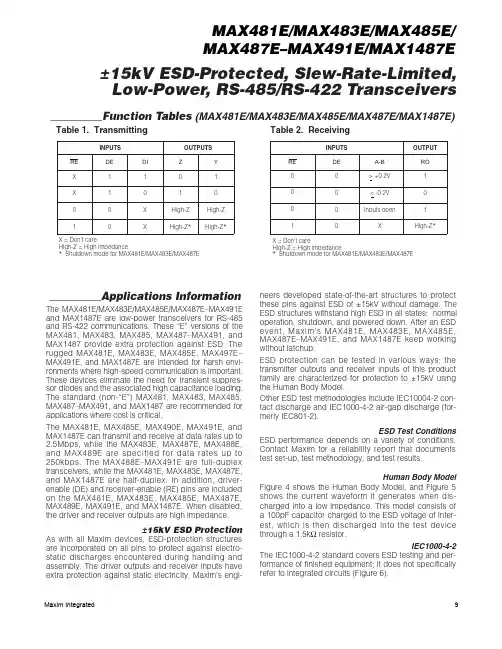
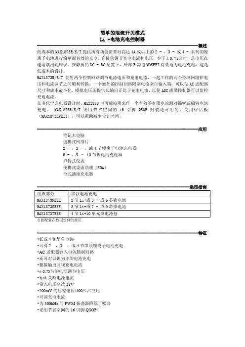
MAX4837EUT28BD1-T中文资料
- 格式:pdf
- 大小:356.52 KB
- 文档页数:12
General DescriptionThe MAX4836/MAX4837 family of low-dropout (LDO)linear regulators feature an accurate current-limiting switch with an integrated FLAG or RESET function. These devices operate from 2.5V to 5.5V and deliver up to 500mA of load current at a preset output voltage. Preset output voltage levels are 1.8V/2.5V/2.8V/3.0V/3.3V.The MAX4836/MAX4837 offer a programmable soft-start control function to eliminate false reset during startup. The MAX4836 provides a FLAG function to noti-fy the system when the load current exceeds the limit.The MAX4837 provides a RESET function to notify the system when the output drops below the threshold.Additionally, reverse-current protection prevents cur-rent flowing from the output to the input. Other features include a low 90µA quiescent current, a 0.1µA shut-down current.The MAX4836/MAX4837 are available in space-saving 6-pin SOT23 and TDFN packages. Each device is speci-fied over the -40°C to +85°C extended temperature range. Contact factory for other programmed output volt-age versions from 1.5V to 3.3V in 100mV increments.For pin-compatible 100mA versions of this device, refer to the MAX4832/MAX4833. For pin-compatible 250mA versions of this device, refer to the MAX4834/MAX4835.ApplicationsSDIO Ports and Devices Notebook Computers USB Ports and Devices Cell Phones PDAs and Palmtop DevicesGPS SystemsFeatures♦Guaranteed Minimum 500mA Load Current♦Accurate Current Limit♦Preset Output Voltages: 1.8V/2.5V/2.8V/3.0V/3.3V ♦2.5V to 5.5V Supply Voltage Range ♦Adjustable Soft-Start ♦Low Dropout Voltage ♦Thermal Shutdown♦Reverse-Current Protection♦Shutdown Output Discharge (MAX4837)♦Low 90µA Supply Current♦Ultra-Low 0.1µA Shutdown Current ♦FLAG and Latch Off (MAX4836) or RESET (MAX4837)♦Tiny SOT23 and TDFN (3mm x 3mm) PackagesMAX4836/MAX4837500mA LDO Linear Regulators withCurrent-Limiting Switch________________________________________________________________Maxim Integrated Products1Ordering Information19-3374; Rev 0; 7/04For pricing, delivery, and ordering information,please contact Maxim/Dallas Direct!at 1-888-629-4642, or visit Maxim’s website at .Note:“xy” are placeholders for the output voltage levels of the devices. Insert the values found in Table 1 at the end of this doc-ument in the place of “xy”. The “_” is a placeholder for either the RESET or the FLAG feature. Insert “B” in the place of “_” for RESET and “C” for FLAG . “dd” is a placeholder for the reset timeout period. Insert the values found in Table 2 in the place of “dd.” For example, MAX4837EUT18BD2 has a 1.8V output volt-age, RESET feature, and a 30ms reset timeout period. Note that “dd” applies only to the devices with RESET option and does not apply to the devices with FLAG option. For devices with the FLAG option, leave dd blank. Standard versions require a mini-mum order increment of 2.5k units. Nonstandard versions must be ordered in 10k unit increments. Contact factory for availability.*Future product—contact factory for availability.Pin ConfigurationsTables 1 and 2 and Selector Gui de appear at end of data sheet.M A X 4836/M A X 4837500mA LDO Linear Regulators with Current-Limiting SwitchABSOLUTE MAXIMUM RATINGSELECTRICAL CHARACTERISTICSStresses beyond those listed under “Absolute Maximum Ratings” may cause permanent damage to the device. These are stress ratings only, and functional operation of the device at these or any other conditions beyond those indicated in the operational sections of the specifications is not implied. Exposure to absolute maximum rating conditions for extended periods may affect device reliability.IN, SHDN , FLAG , OUT to GND ................................-0.3V to +6V RESET to GND .........................................-0.3V to (V OUT + 0.3V)SS to GND ...................................................-0.3V to (V IN + 0.3V)IN to OUT...............................................................................±6V OUT Short Circuit to GND..........................................Continuous All Pins ESD Handling (Human Body Model).........................2kVContinuous Power Dissipation (T A = +70°C)6-Pin SOT23 (derate 9.1mW/°C above +70°C)................727mW 6-Pin TDFN (derate 24.4mW/°C above +70°C)..........1951.2mW Operating Temperature Range ...........................-40°C to +85°C Operating Junction Temperature Range...........-40°C to +125°C Storage Temperature Range.............................-65°C to +150°C Lead Temperature (soldering, 10s).................................+300°CMAX4836/MAX4837500mA LDO Linear Regulators withCurrent-Limiting Switch_______________________________________________________________________________________3Note 2:The dropout voltage is measured from V IN to V OUT when V OUT is 2% below its nominal value. The nominal output voltage ismeasured from V OUT to GND when V IN is 1V greater than V OUT . Defined only for V OUT ≥2.5V.Note 3:Soft-start time is defined as the time required for the output to rise from 10% of its nominal value to 90% of its nominal value.Note 4:For V OUT < 2V, V IN must be above 2.5V.Note 5:This is the maximum time OUT can be out of tolerance before a reset is issued. It is implemented to ensure that momentaryoutput glitches do not trigger a reset condition.Note 6:In startup mode, the blanking time counter is not started until the soft-start time has elapsed. The total time from startup toFLAG issued is t SS + t BLANK .ELECTRICAL CHARACTERISTICS (continued)M A X 4836/M A X 4837500mA LDO Linear Regulators with Current-Limiting Switch 4_______________________________________________________________________________________Typical Operating Characteristics(V IN = V OUT + 1V, SHDN = IN, C OUT = 3.3µF, T A = +25°C, unless otherwise noted.)QUIESCENT CURRENT vs. INPUT VOLTAGE(NO LOAD)V IN (V)I Q (µA )5432120406080100120006QUIESCENT CURRENT vs. INPUT VOLTAGE(500mA LOAD)V IN (V)I Q (µA )5432161002003004005006007008000MAXIMUM TRANSIENT DURATION vs. RESET THRESHOLD OVERDRIVERESET THRESHOLD OVERDRIVE (mV)P U L S E D U R A T I O N (µs )1015304560759001100DROPOUT VOLTAGE vs. LOAD CURRENTLOAD CURRENT (mA)D R O P O U T V O L T A GE (m V )40030020010030609012015018000500POWER-SUPPLY REJECTION RATIOvs. FREQUENCYFREQUENCY (kHz)P S R R (d B )1010.1-70-60-50-40-30-20-100-800.01100REGION OF STABLE C OUT ESRvs. LOAD CURRENTLOAD CURRENT (mA)C O U T E S R (Ω)1234567450400350300250200150100500500OUTPUT NOISE vs. FREQUENCYFREQUENCY (Hz)O U T P U T N O I S E (µV R M S )10k1k 1001020304050010100kSOFT-START RESPONSE (C SS = FLOATING)V SS 1V/divV OUT 2V/div V IN 2V/div2ms/divt SS_______________________________________________________________________________________5MAX4836/MAX4837500mA LDO Linear Regulators withCurrent-Limiting SwitchSOFT-START RESPONSE(C SS = 0.01µF)V SS 1V/divV OUT 2V/divV IN 2V/div2ms/divt SSSOFT-START RESPONSE(C SS = 0.1µF)V IN 2V/divV SS 1V/divV OUT 2V/div20ms/divt SSLOAD-TRANSIENT RESPONSEV OUT 50mV/div AC-COUPLED100µs/divV IN = 4.3V V OUT = 3.3V C IN = 0.1µF C OUT = 3.3µFI LOAD : STEP FROM 10mA TO 100mA BACK TO 10mALOAD-TRANSIENT RESPONSENEAR DROPOUTV OUT 50mV/div AC-COUPLED100µs/divV IN = 3.4V V OUT = 3.3V C IN = 0.1µF C OUT = 3.3µFI LOAD : STEP FROM 10mA TO 100mA BACK TO 10mALINE-TRANSIENT RESPONSEV OUT 50mV/div AC-COUPLED100µs/divC IN = 0.1µF C OUT = 3.3µF V OUT = 3.3V I LOAD = 10mA5V V IN500mV/div 4.5V RESET RESPONSE TO V INV RESET 2V/divV OUT 2V/divV IN 2V/div40ms/divt RESETC SS = FLOATINGRESET RESPONSE TO V OUTV RESET 1V/divV OUT 1V/div40ms/div t RESETV IN = 3.5V, C SS = FLOATINGRESET RESPONSE TO SHUTDOWNV RESET 2V/divV OUT 2V/divV SHDN 2V/div40ms/divt RESETV IN = 3.5V, C SS = FLOATINGTypical Operating Characteristics (continued)(V IN = V OUT + 1V, SHDN = IN, C OUT = 3.3µF, T A = +25°C, unless otherwise noted.)M A X 4836/M A X 4837500mA LDO Linear Regulators with Current-Limiting Switch 6_______________________________________________________________________________________Typical Operating Characteristics (continued)(V IN = V OUT + 1V, SHDN = IN, C OUT = 3.3µF, T A = +25°C, unless otherwise noted.)FLAG RESPONSE WHEN OUT IS SHORTED TO GND < BLANKING TIMEMAX4836 toc17V OUT 2V/div1ms/divI OUT200mA/divV FLAG 5V/divFLAG RESPONSE WHEN OUT IS SHORTED TO GND > BLANKING TIME(IN IS TOGGLED)V OUT 1V/div 10ms/divV IN 2V/divV 2V/divFLAG CONNECTED TO LOGIC SUPPLYt BLANKSTARTUP IN AN OVERLOAD CONDITION(C SS NOT CONNECTED)V SS 1V/divV 2V/div V OUT 2V/div2ms/divt BLANKV IN 2V/divt SSV OUT = 2.5VI LOAD = I LIMIT MAXIMUMFLAG CONNECTED TO LOGIC SUPPLYSTARTUP IN AN OVERLOAD CONDITION(C SS = 0.01µF)V SS 1V/divV 2V/divV OUT 2V/div4ms/divt BLANKV IN 2V/divt SSV OUT = 2.5VI LOAD = I LIMIT MAXIMUMFLAG CONNECTED TO LOGIC SUPPLYNORMALIZED OUTPUT VOLTAGEvs. TEMPERATURETEMPERATURE (°C)N O R M A L I Z E D O U T P U T V O L T A G E 603510-150.9960.9981.0001.0021.0040.994-4085FLAG RESPONSE WHEN OUT IS SHORTED TO GND > BLANKING TIME(SHDN IS TOGGLED)V OUT 1V/div 10ms/divV 2V/divV 2V/divFLAG CONNECTED TO LOGIC SUPPLYt BLANKDetailed Description The MAX4836/MAX4837 are ultra-low quiescent current, low-dropout linear regulators with an integrated current limiter. These devices guarantee up to 500mA drive capabilities and regulate the preset output voltage.The MAX4836 has a flag output that asserts low when the load current exceeds the current limit for more than the blanking time (t BLANK). The MAX4837 has a reset output that asserts low when the regulator output volt-age is below the reset threshold voltage (V RESET). V RESET is 87.5% of the nominal output voltage. Figure 1 shows the simplified functional diagram and Figure 2 shows the typical application circuits.FLAG Output (MAX4836) The open-drain FLAG output goes low and the LDO’s pass transistor is latched off when the current in the pass transistor is at its output current limit for more than the blanking time (t BLANK). Cycling IN or SHDN(high to low to high) brings the device out of its latched-off state and back into normal operation.RESET Output (MAX4837)The RESET output asserts when one of the following conditions occurs:•The input voltage (V IN) is below the input undervolt-age lockout threshold (V UVLO).•The output voltage (V OUT) is below the reset thresh-old (V RESET).•SHDN is pulled low.•The device is in thermal shutdown.•When V OUT> V IN.RESET remains low for the reset timeout period (t RESET)after reset conditions are terminated. There are four RESET timeout periods available as shown in the Electrical Characteristics table. RESET is available in apush-pull configuration as shown in the Selector Guide.ShutdownPull SHDN low to shut down the LDO and reduce the quiescent current consumption of the device from 90µAto 0.1µA. In shutdown mode, the pass transistor, con-trol circuit, and reference circuit are turned off. Connect SHDN to a supply voltage greater than V IH to turn onthe LDO.MAX4836/MAX4837500mA LDO Linear Regulators withCurrent-Limiting Switch _______________________________________________________________________________________7M A X 4836/M A X 4837500mA LDO Linear Regulators with Current-Limiting Switch 8_______________________________________________________________________________________Figure 2. Typical Application CircuitsShutdown Discharge (MAX4837) OUT discharges through a 900Ωinternal resistor during shutdown mode.Reverse OUT to IN Current When the output voltage is greater than the input volt-age, the internal pass transistor turns off. To avoid reverse-charging the input source, the current at IN is guaranteed to be below 3µA when V OUT≥V IN.Current Limit The MAX4836/MAX4837 include an accurate internal current-limiting circuit. OUT can be shorted to ground indefinitely without damaging the part.The MAX4836 latches off if the load current exceeds the current limit for more than the blanking time (see the FLAG Output section). During soft-start, the device does not latch off to an overload condition. During an overload condition, the MAX4837 holds the current at current limit until the thermal limit is reached. Once the junction tem-perature reaches +165°C, thermal shutdown occurs.Thermal Shutdown When the junction temperature (T J) exceeds +165°C, the LDO’s pass transistor turns off allowing the junction to cool. The LDO’s pass transistor turns on again after the IC’s junction temperature cools by 15°C, resulting in a pulsed output during continuous thermal-overload conditions.Soft-Start During power-up, the soft-start ensures that the output ramps up slowly reducing inrush current peaks. See the soft-start response time plots in the Typical Operating Characteristics. The soft-start time (t SS) is given by the following equation:t SS= C SS(ms)where C SS is in nF.A soft-start capacitor (C SS) of 10nF gives a 10ms t SS. A 1ms minimum soft-start time is fixed internally to ensure that the output rises slowly even without any external capacitor at SS pin to ground. The device is in soft-start mode when either the voltage at IN or SHDN is cycled high to low to high.Applications InformationCapacitor Selection and RegulatorStabilityFor stable operation over the full temperature range andwith load currents up to 500mA, use a 3.3µF (min) ceramic output capacitor with an ESR <0.2Ω. To reducenoise and improve load transient response, stability, and power-supply rejection, use larger output capacitor values such as 10µF (note that some ceramic capacitors exhibit large capacitance and ESR variation with temper-ature). X7R capacitors provide good performance overthe -40°C to +85°C operating temperature range.To improve power-supply rejection and transient response, use a 0.1µF capacitor between IN and GND.The MAX4836/MAX4837 remain stable with purely resistive loads or current loads up to 500mA.15kV Operational ESD ProtectionA 3.3µF or higher value ceramic capacitor from OUT toGND provides a 15kV (Human Body Model) protectionat OUT. The ESR value of the capacitor should be lessthan 0.2Ω.Reset Transient ImmunityThe reset circuit is relatively immune to short duration,falling V OUT transients. The Typical Operating Characteristics show a graph of the Maximum Transient Duration vs. Reset Threshold Overdrive for which reset isnot asserted. The graph was produced using falling V OUT transients starting at V OUT and ending below the reset threshold by the magnitude indicated (reset threshold overdrive). The graph shows the maximum pulse widththat a falling V OUT transient can typically have without triggering the reset pulse. As the amplitude of the tran-sient increases (i.e., goes further below the reset thresh-old), the maximum allowable pulse width decreases. Typically, a V OUT transient that goes only 10mV below thereset threshold and lasts up to 54µs does not trigger areset pulse.LayoutWhen using the TDFN package, connect its exposed paddle to G ND to provide a low thermal resistancepath for heat transfer from the IC junction to the printedcircuit board.MAX4836/MAX4837500mA LDO Linear Regulators withCurrent-Limiting Switch _______________________________________________________________________________________9M A X 4836/M A X 4837500mA LDO Linear Regulators with Current-Limiting Switch 10______________________________________________________________________________________Table 1. Standard Output Voltage Suffix 100mV increments. Contact factory for availability.Table 2. R E S E T Timeout Period SuffixPin Configurations (continued)Chip InformationTRANSISTOR COUNT: 1575PROCESS: BiCMOSTDFN Exposed Pad: Connected to GNDMAX4836/MAX4837500mA LDO Linear Regulators withCurrent-Limiting SwitchPackage Information(The package drawing(s) in this data sheet may not reflect the most current specifications. For the latest package outline information go to /packages .)M A X 4836/M A X 4837500mA LDO Linear Regulators with Current-Limiting Switchimplied. Maxim reserves the right to change the circuitry and specifications without notice at any time.12____________________Maxim Integrated Products, 120 San Gabriel Drive, Sunnyvale, CA 94086 408-737-7600©2004 Maxim Integrated ProductsPrinted USAis a registered trademark of Maxim Integrated Products.Package Information (continued)(The package drawing(s) in this data sheet may not reflect the most current specifications. For the latest package outline information go to /packages .)。