DeviceNet的故障排除
- 格式:docx
- 大小:56.67 KB
- 文档页数:15
DveicNet网络故障诊断指导¾DeviceNet介绍¾DeviceNet故障诊断方式¾常规检测检查清单¾电气检查清单¾分割网络诊断DeviceNet是一种5芯数字通讯网络。
在V+和V-之间有24V网络电源,CAN_H和CAN_L两根电缆用于信号通讯,第五根电缆是屏蔽电缆,在和V-连接后设置网络上的唯一接地点。
(续)DeviceNet网络是一种主干/分支的拓扑结构,设备(或节点)通过T接头或分路器连接到主干网的不同节点上,在网络(主干)两端必须有终端电阻。
2. DeviceNet故障诊断方式大部分网络故障可以用两种工具(数字万用表和网络检测仪)来进行检测。
通常的网络故障是硬件故障可以通过常规进程进行诊断。
1.遇到网络故障可以从常规检测的检查清单开始。
单独的节点问题通常通过更换节点上的设备或和设备关联的元器件(T接头,分支电缆)来解决。
2.若故障依旧或间歇存在,可以用网络诊断仪检测根本原因。
这个仪器可以检测bus故障和其他边界条件的网络故障。
另外,网络诊断仪可以不中断网络运行连接到网络(可监测)中。
3.Bus-off的问题通常可以通过“分割网络”方式进行排故,用网络诊断仪进行检测可以获得更多的信息。
4.对于间歇或持久故障,上述方式仍然没有检测到根本原因,用电气测试的方式可以解决网络的常规故障(接线,接地等)。
提醒:1.若Scanner有bus off(代号91)报警,对DeviceNet Scanner进行重新上电可以清楚这个故障。
小贴士:通常的做法是将Scanner在机架上拔下再安装。
2.切断主干网或终端电阻会导致网络bus off报警。
当按照“分割网络”的步骤进行时必须在每一步后重置网络。
3.对PLC槽架的重上电可以复位Scanner但不能复位网络上的其他设备。
小贴士:重置整个网络,必须重置网络电源,这个电源通常在MCP柜中。
4. RSNetworxs for DeviceNet这个软件对bus off的故障排除不是一个有用的工具。


DeviceNet模块手册一、概述DeviceNet是一种用于工业自动化领域的网络通信协议,它基于CAN总线技术,专为工业设备之间的数据交换而设计。
通过使用DeviceNet模块,可以实现设备之间的快速、可靠的数据传输,支持多种通信速率和传输介质。
二、DeviceNet模块特点1、支持多种通信速率:DeviceNet模块支持多种通信速率,可以根据实际需求选择合适的通信速率,以满足不同设备的通信需求。
2、支持多种传输介质:DeviceNet模块支持多种传输介质,如双绞线、光纤等,可以根据实际应用场景选择合适的传输介质,以确保数据传输的稳定性和可靠性。
3、高效的数据传输:DeviceNet模块采用高效的通信协议,支持实时数据传输和广播通信,可以实现设备之间的快速数据交换。
4、灵活的连接方式:DeviceNet模块采用即插即用的连接方式,可以方便地连接各种工业设备,如传感器、执行器、控制器等。
5、可靠的故障检测机制:DeviceNet模块具有可靠的故障检测机制,可以实时检测通信故障,并及时进行故障隔离和恢复,以确保数据传输的可靠性和稳定性。
三、DeviceNet模块应用场景DeviceNet模块广泛应用于各种工业自动化领域,如智能制造、机器人、电力、石油、化工等。
在这些领域中,DeviceNet模块可以用于实现设备之间的数据传输和控制,提高生产效率和管理水平。
四、DeviceNet模块使用注意事项1、确保传输介质的质量:在选择和使用传输介质时,要确保其质量可靠,以满足数据传输的需求。
同时,要注意对传输介质的维护和保养,定期检查其状态。
2、合理配置通信参数:在使用DeviceNet模块时,要根据实际需求合理配置通信参数,如通信速率、数据位长度、停止位长度等。
同时,要注意参数配置的一致性,以确保设备之间的正常通信。
3、避免电磁干扰:在工业环境中,电磁干扰是常见的问题之一。
在使用DeviceNet模块时,要注意避免电磁干扰的影响,采取措施降低干扰的影响,如使用屏蔽线、加装滤波器等。

DeviceNet will not function correctly if design rules are not followed.Even a Network previously thought to be functioning correctly may beginto exhibit abnormal or anomalous operation due to incorrect system design.The following are tips to help locate and correct these abnormalities.For specific DeviceNet system installation information.Please refer the "DeviceNet Planning and Installation Manual".Manuals can be ordered via the Internet at /Verify that all devices on the network have been certified by ODVA andcarry the DeviceNet Conformance check on their name plate.Termination Resistors:A termination resistor equal to 121 Ohms 1% , 1/4W must be attached at each end of the Trunk cable. The resistors must be connected across the Blue & White wires of the DeviceNet cable.Resistor connection can be verified by disconnecting DeviceNet power and measuring the resistance across the Can_H & Can_L lines (Blue & White Wire). This can be measured with an Ohm meter. The reading should be approximately60 Ohms.Very Important:The DeviceNet network will not operate correctly without terminating resistors. Termination resistors can be ordered from your local Allen-Bradley Distributor using the part number 1485A-C2.Network Grounding:The DeviceNet cable must by grounded at only one location. This should be done closest to the center of the network. Connect the network Shield and Drain wire to an earth ground using #8 AWG wire up to a maximum 3m ( 10Ft ) in length.Also connect the V- conductor ( Black Wire) of the network trunk cable and the DC ground of the power supply to this ground connection.DeviceNet requires 24VDC. Use a power supply rated 24VDC (+/- 1% ). Make sure the power supply has it's own current limit protection. Provide fuse protection for each segment of the cable system. DeviceNet requires a power supply to have a rise time of less then 250mS to within 5% of its rated output voltage. The power supply must be sized correctly to provide each device with its required power.1. The thin wire trunk line can only handle 3 amps and the thick wire trunk line can physically handle 8 amps. However, in North America the current is limited to 4 amps. Multiple power supplies can be installed on a DeviceNet network, but no section of cable should have more current flowing than the appropriate rating. An important note is that when putting multiple power supplies on a network; break the Red V+ wire between the power supplies. This effectively isolates the power supplies from each other.2. Common mode voltage can sometimes be an issue on DeviceNet networks which have trunk lines that are extra long and/or have devices on them, drawing large currents at longer distances. If the voltage on the Black V- wire ever gets more than 4.65 volts different from one point of the network to another, then communication problems could occur. On an existing network, if the voltage between the Red V+ wire and the Black V- wire ever gets below 15 volts, then common mode voltage could be adversely affecting network communications. Adding an additional power supply or moving an existing power supply closer to the heavier current loads will normally cure common mode voltage problems.It is recommended that the DeviceNet power supply should be used to power the DeviceNet network only. When multiple power supplies are required, verify that the V+ connection is broken between the supplies. Please refer to the " DeviceNet Planning and Installation Manual " for more specific installation procedures.Verify Network VoltagesIt needs to be understood that DeviceNet is actually a three wire Differential Voltage network communication is accomplished by switching the CAN-H (White wire) and CAN-L (Blue wire) signals relative to the V- line ( Black Wire ). The CAN-H swings between 2.5 VDC (Recessive State) and 4.0 VDC (Dominant State) while the CAN-L swings between 1.5 VDC (Dominant State) and 2.5 VDC (Recessive State)Without a network master connected to the DeviceNet, the CAN-H and CAN-L lines should read between 2.5 VDC and 3.0 VDC relative to V- and the voltages should be identical. (Recessive State). Measure these voltages right at the SDN scanner. Use a voltmeter in DC mode.With a network master connectedwill be around +3.2 VDC. The CAN-L to V- voltage will be around 2.4 VDC. The reason these values appear a little different than the ranges shown on the scope trace, is that the signals are switching, which slightly affects the DC value being read by the VOM.If Can-H to V- and Can_L to V- are too low; less than 2.5 V dc and 2.0 V dc respectively the issue is probably a bad transceiver or bad wiring. To find a bad transceiver remove one node at a time measuring Can-H and Can-L to V- each time a device is removed.To check a transceiver (rough test) with everything removed from a device use an ohm meter to measure resistance between V+ and Can-H V+ and Can-L V- and Can-H V- and Can-L. These impedances should all be greater than 1 M ohm.Examine the System Design of the InstallationWalk the network if possible to determine the actual layout. ( Make a sketch of the network )Check number of nodesCheck cumulative drop lengthCheck individual drop lengthsCheck branched drop lengthCheck total trunk length, including long drop near the endsCheck the termination location and measure the terminatorsCheck the power supply cable length and gaugeCheck for one, and only one, earth ground of the V- and shieldBreak the combination shield/V- connection to frame ground and verify >1.0 Mohm to frame groundCheck for one and only one V- to shield connectionBreak the shield/V- connection at the power supply and verify >1.0 Mohm shield to V- with 24VDC offCheck for shorts of CAN- and/or CAN+ to shield or V- verify with an OHM meterCheck the length and gauge of the earth ground connectionCheck total power load and its distribution pointsCheck trunk and drop current limitsCheck type (size and length) of cable bringing power into the trunkMeasure the 24V supply at the middle and ends of the networkConsider spot checking the power for noise with an oscilloscopeIt is recommended but not required that the 24 VDC Network Power for DeviceNet should be used for the DeviceNet network only to aid in eliminating noise issues.Check the WiringCheck lead dress in junction boxesCheck that connectors are screwed together tightlyCheck that glands are screwed tightlyCheck for foreign material (electrical tape, RTV, etc.) in glandsCheck that nodes are not touching extremely hot or cold surfacesCheck that cables are kept a few inches away from power wiringCheck that cables are not draped on electric motors, relays, contactors or solenoids Check that cables are not constrained so as to place excessive tension on connectors Wiggle connectors to provoke intermittent failuresCheck the Scanner ConfigurationVerify the scanlistBaud RateNode AddressSeries/Revision of the 1747/1771-SDN scannerRefer to Knowbase for documents on factory defaulting DeviceNet Scanners Check the NodesCycle power to the 24V supply, this will reset the scanner to initialize the network Examine the scanner display codes to identify problem nodes.( Reference the SDN manual for a description of these codes )At problem nodesBlinking GREEN means the node is not being allocated by the scannerCheck that the node is in the scan listCheck that the scanner is not bus offCheck if connection is timing outBlinking RED means no communicationCheck for missing power on all nodesCheck if all other nodes are disconnectedCheck node baud rate ( Bad baud rate does not always cause buss off )Check scanner, if a code 91 is displayed then the communications connection with the node has timed out. Recycle 24V supply and then reset scanner.If scanner goes bus off again, The problem is some combination of Defective node•••••••••••Node baud rate Bad topologyBad connections Bad scannerBad powerBad grounding Bad electrical noiseA Solid RED light at power-up means two nodes have the same address.A Solid RED after allocation means bus off Check baud rate.If the problems persist:Replace T-TapCheck topologyCheck power for noise with oscilloscope or power disturbance analyzer Finally if the problem remains after all else has been tried replace the node.( Be sure to set the node address and baud rate on the replacement node, if applicable )Points to RememberPressing the reset button on the scanner does not reset the network •••••••••Cycling the rack power does not reset the networkWhen using a DeviceLink a bus off (solid RED) condition can only be cleared by cycling the 24V powerCycling power on the network will cause the scanner to go bus offDeviceNet 9000 bus off (solid RED) condition can be cleared by cycling the 24V power or by pressing the program button for several secondsExtreme care must be given to the task of setting initial addresses and baud rates because one incorrect node address or incorrect baud rate will cause other nodes to appear to be bad (solid RED).If the scanner is bus off (code 91), nodes will not re-allocate (flashing GREEN or RED) even if they are functioning correctlyRSNetworx for DeviceNet and a 1770-KFD/1784-PCD can be used to identify the functioning nodes on the network.If a node goes bus off (solid RED for DeviceLink), and is replaced and still goes bus off, the problem is not the node but rather the setting of the address or baud rate or a network wide problem related to topology, grounding, electrical noise or an intermittent node•••Try to distinguish, as soon as possible, a device problem from a media problem.Try to reduce the system to the smallest size, which still exhibits the problem. This can be done by removing nodes, drops, taps, or lengths of trunk can do this.Use substitution where possible to rule things out, but be careful!Product A works with Product B and not with Product C.We conclude that the problem is with Product C -- WRONG!!The problem was with product A., Product C was operating correctly, But just happened to be Susceptible to the fault in the product A.Always remember do not assume too much!If you suspect a media problem, inspection is always a good first step.Verify lengths, topology, and proper termination ( VERY IMPORTANT ).Always. Always, ALWAYS!!........... Check all Connections.Opens or shorts may be the biggest problem. On an idle bus (without traffic) voltages can indicate problems. CAN_L and CAN_H should be about 2.5 to 3.0 volts relative to V-. If there is traffic, CAN_L will be a little lower, CAN_H a little higher.Use an OHM meter to check resistance between CAN_H and CAN_L when idle. This should be about 60 ohms (two 120 ohm terminators in parallel). This value may be as low as 50 ohms if there are many nodes attached. Make sure all wires are well attached to the right places. The V+ level, relative to V-, should always be between 11 to 25 volts.One common problem people run across is incorrect setting of baud rates and node addresses. Always verify the nodes address and baud rate before installing it on a network. And try not to change a nodes baud rate while on the network. Do all baud changes on a point-to-point only connection.Ground LoopsBefore trying this make sure the shield is grounded in only one place.Use the oscilloscope to determine if there are ground loops in your system. You should NOT see 60 Hz or Harmonics in your signal. Assuming you use DC coupling on the oscilloscope you should see....2.8 VDC offset on both Can_High & Can_Low NO Sinusoidal signal; ie 60 Hz components.COMBLACK Common --CAN_L--BLUE-- SignalLowSHIELD--UninsulatedShield--CAN_HHighWHITE Signal--VDC+SupplyRED PowerGROUNDEARTHGREEN ChassisGround --DeviceNet QD ConnectorsExamining the connector with the keyway pointing down. Number the pins starting at the pin right most to the keyway (1) and continue counter clockwise until you reach pin (5).PIN 1 SHIELD GREEN ( or Bare wire )VDC+ RED2PINBLACKCOMPIN3WHITECAN_HIGHPIN4PIN 5 CAN_LOW BLUEMicro QD Cable Mini QD CableBlack * Blue * Shield * White * RedRecommended for daisy-chain network connectionsDeviceNet Flat MediaFlat media connectors are available in Micro/Mini Quick Disconnect and Open Style. Flat Media helps speed up network installation as well eliminating wiring mistakes.DeviceNet Scanner Status / Error CodesThe bicolor (GREEN/RED) module status indicator displays device status. It indicates whether the device has power and is functioning properly.Indicator is Then Take this action------------------|---------------------------------------------|-----------------------| Off | There is no power applied to the device. | Apply power.| |Green | The device is operating in normal condition.| Do nothing.| |Flashing Green | The device needs configuring. | Configure the device.| |Flashing Red | There is an invalid configuration. | Verify dip switch| | settings.| | Check configuration| | setup.| |Red | The device has an unrecoverable fault. | Replace the module.------------------|---------------------------------------------|-----------------------|The network status indicator is a bicolor (GREEN/RED) LED. The following table provides troubleshooting information about communication links.Indicator is Then Which Indicates Take this action-------------|-----------------------------|--------------------|-----------------------| Off | The device has no power or | The channel is |Power-up the scanner,| the channel is disabled for | disabled for |provide network power| communication due to bus off| DeviceNet |to channel, and make| condition, loss of network | communication |sure channel is| power, or has been | |enabled in both the| intentionally disabled. | |scanner configuration| | |table and module command | | |word.-------------|-----------------------------|--------------------|-----------------------| Flashing |The two-digit numeric display| The channel is |Configure scan list Green |for the channel indicates an | enabled but no |table for channel|error code that provides more| communication is |to add devices|information about the | occurring ||condition of the channel | |-------------|-----------------------------|--------------------|-----------------------| Solid Green | There's normal operation |All slave devices in|| |the scan list table || |are communicating | Do Nothing| |normally with the || |scanner |-------------|-----------------------------|--------------------|-----------------------|Solid Red |The communications channel |The scanner may be |Reset module. If|has failed.The two digit |defective. |failures continue,|numeric display for the | |replace module.|channel displays an error | ||code that provides more | ||information about the | ||condition of the channel | |-------------|-----------------------------|--------------------|-----------------------| Flashing Red |The two-digit numeric display|At least one of the |Examine the failed|for the channel display an |slave devices in the|device and check the|error code that provides more|scanner's scan list |scan list table|information about the |table has failed to |for accuracy.|condition of the channel. |communicate with the|| |scanner.The network || |has faulted. |-------------|-----------------------------|--------------------|-----------------------|Your 1747/1771-SDN Scanner Module has a node address/status indicator that uses numeric displays to indicate diagnostic information about your module. The display flashes at approximately 1 second intervals, depending on network traffic. The following table summarizes the meanings of the numeric codes.Numeric Code Description Take this action---------------|-----------------------------------------|------------------------------| Network Address|Normal operation. The numeric display | Do nothingDisplays |matches the scanner's node address on the|0 - 63 |DeviceNet network |---------------|-----------------------------------------|------------------------------| |Scanner failed Duplicate Node Address |Change the scanner channel70 |check |address to another available| |one. The node address you| |selected is already in use on | |that channel.---------------|-----------------------------------------|------------------------------| |Illegal data in scan list table |Reconfigure scan list table71 |(node number alternately flashes). |and remove any illegal data.| |---------------|-----------------------------------------|------------------------------| |Slave device stopped communicating |Inspect the field devices and72 |(node number alternately flashes). |verify connections.| |---------------|-----------------------------------------|------------------------------| |Device's identity information does not |Verify that the correct device73 |match electronic key in scan list table |is at this node number.|entry (node number alternately flashes). |Make sure that the device at| |the flashing node address| |matches the desired electronic | |key (vendor, product code,| |product type).---------------|-----------------------------------------|------------------------------|| |Modify your configuration and74 |Data overrun on port detected. |check for invalid data.| |Check network communication| |traffic.---------------|-----------------------------------------|------------------------------| |No network traffic at all has been |Verify connections.75 |detected. || |---------------|-----------------------------------------|------------------------------| |No direct network traffic for scanner |None. The scanner hears other76 |detected. |network communication.| |---------------|-----------------------------------------|------------------------------| |Data size expected by the device does |Reconfigure your module for77 |not match scan list entry |the correct transmit and|(node number alternately flashes). |receive data sizes.---------------|-----------------------------------------|------------------------------| |Slave device in scan list table does not |Add the device to the network,78 |exist (node number alternately flashes). |or delete the scan list entry | |for that device.---------------|-----------------------------------------|------------------------------| |Scanners duplicate node check |Make sure that your module is79 |was not acknowledged or module failed to |connected to a valid network.|transmit a message. |Check for disconnected cables. | |Verify baud rate.---------------|-----------------------------------------|------------------------------| | |Enable RUN bit in SDN module80 |Scanner is in IDLE mode. |command register.| |Put PLC/SLC in RUN mode.---------------|-----------------------------------------|------------------------------| |Scanner is in FAULT mode. |Check ladder program for81 | |fault bits being set in SDN.---------------|-----------------------------------------|------------------------------| |Error detected in sequence of fragmented |Check scan list table entry for82 |I/O messages from device |slave device to make sure that |(node number alternately flashes). |input and output data lengths| |are correct. Check slave| |device configuration.---------------|-----------------------------------------|------------------------------| |Slave device is returning error responses|Check accuracy of scan list83 |when scanner attempts to communicate with|table entry. Check slave device |it (node number alternately flashes). |configuration. Slave device may | |be in another master's scan| |list. Reboot slave device.---------------|-----------------------------------------|------------------------------| |Scanner is initializing the DeviceNet |None. This code clears itself84 |channel. |once scanner attempts to| |initialize all slave devices| |on the channel.---------------|-----------------------------------------|------------------------------||Data size larger than 255 bytes |Configure the device for a85 | |smaller data size. OR the|OR a run time data size error received. |slave has a variable| |connection size which AB| |scanners do not support.---------------|-----------------------------------------|------------------------------| |Device is producing zero length data |Check device configuration86 |(idle state) while channel is in |and slave node status.|Run Mode. |---------------|-----------------------------------------|------------------------------|88 |Shared inputs error also appears at |Check connection of master to |power-up and reset, the module displays |slave that is configured for|all 14 segments of the node address and |shared inputs - it may be|status display LEDs. |powered down or disconnected.---------------|-----------------------------------------|------------------------------|89 |This is an ADR error. The Device does |Check configuration or disable |not support the Auto-Device Recovery |the ADR function for this|or is not configured properly. |device.---------------|-----------------------------------------|------------------------------| |User has disabled communication port |Reconfigure your module.90 | |Check Module Command Register. | |---------------|-----------------------------------------|------------------------------| |Bus-off condition detected on comm port. |Check DeviceNet connections and91 |Scanner is detecting communication errors|physical media integrity.Check | |system for failed slave devices | |or other possible sources of| |network interference.---------------|-----------------------------------------|------------------------------| |No network power detected on comm port. |Provide network power.92 | |Make sure that scanner drop| |cable is providing network| |power to scanner comm port.---------------|-----------------------------------------|------------------------------| |Application FLASH update in progress. |None. Do not disconnect the95 | |module while application FLASH | |is in progress. You will lose| |any existing data in the| |scanner's memory.---------------|-----------------------------------------|------------------------------| |Scanner halted by user command. |Check ladder program for cause97 | |of fault bits.| |---------------|-----------------------------------------|------------------------------| |Unrecoverable firmware failure. |Service or replace your module98 | || |---------------|-----------------------------------------|------------------------------| |Unrecoverable hardware failure. |Service or replace your module.99 | || |----------------------------------------------------------------------------------------|| |E2 | RAM Test Failure | Return/Replace module| |----------------------------------------------------------------------------------------| | |E4 | Lost Power During FLASH Upgrade | Return/Replace module| |----------------------------------------------------------------------------------------| | |E5 | No Boot or Main Code | Return/Replace module| |----------------------------------------------------------------------------------------| | |E9 | The 1747-SDN scanner has been flushed | Cycle Power on SDN to recover | From the command register. || |----------------------------------------------------------------------------------------|80%-90% of all network problems stem from miswiring, loose connections, opens or shorts during thewiring installation phase.Rockwell Automation now offers the....MediaCheckerProduct Features•Tests your installed network cable for Shorts•Tests your installed network cable for Opens•Displays distance to cable short•Displays distance to cable open•Determines if there are split pairs in twisted cables•Identifies miswiring at connector end•Displays conductors that are miswired•Measures overall network cable length•Measures network termination value (resistance)•Multi language support•DeviceNet - Thick, Thin & KwikLink Flat Media•ControlNet- RG6 Coax cable, DS3/4 cable (Tap)•Ehternet- STP, UTP•Data Highway +•Remote I/OTo order your own MediaCheckercontact your local Rockwell Automation / Allen-Bradleydistributor or sales office and requestCatalog Number 1788-MCHKR。
Devicenet现场总线的普及知识终端电阻在通信中的作用终端电阻是为了消除在通信电缆中的信号反射在通信过程中,有两种信号因导致信号反射:阻抗不连续和阻抗不匹配。
阻抗不连续,信号在传输线末端突然遇到电缆阻抗很小甚至没有,信号在这个地方就会引起反射。
这种信号反射的原理,与光从一种媒质进入另一种媒质要引起反射是相似的。
消除这种反射的方法,就必须在电缆的末端跨接一个与电缆的特性阻抗同样大小的终端电阻,使电缆的阻抗连续。
由于信号在电缆上的传输是双向的,因此,在通讯电缆的另一端可跨接一个同样大小的终端电阻。
引起信号反射的另个原因是数据收发器与传输电缆之间的阻抗不匹配。
这种原因引起的反射,主要表现在通讯线路处在空闲方式时,整个网络数据混乱。
要减弱反射信号对通讯线路的影响,通常采用噪声抑制和加偏置电阻的方法。
在实际应用中,对于比较小的反射信号,为简单方便,经常采用加偏置电阻的方法DeviceNet 网络的使用体会。
(1)DeviceNet现场总线可以节省大量费用。
从安装阶段来看,只通过一根通讯缆,就实现了对整个网上各站点供电及通讯,相对于点对点的控制方式,节省大量的电缆,桥架等。
不但缩短了安装时间,而且降低了安装费用。
从控制上来看:利用网络通讯及“软”I/O方式,也节约了I/O模块和大笔资金。
如对变频器工作站,启动/停止,加速/减速等命令;电压、电流、温度等参数,都可从DeviceNet网络通讯实现,节约了I/O模块,尤其是模拟I/O模块,费用相当昂贵。
(2)设备故障率大大降低,且诊断方便,排除迅速。
DeviceNet由于仅用一条通讯电缆控制整个设备网络,使设备故障率大大降低;各站点通讯端子支持带电热插拔,若某一站点出现问题及故障排除,不影响网上其他站点正常工作。
采用数据通讯方式来控制各站,不但极大减少了传统点对点方式的电缆数量,也使故障环节大大减少,系统稳定性进一步提高。
通过设备网使MCC的集中控制的形式十分有效,极大方便了设备故障的诊断。
DeviceNet网络故障大多都是硬件或网线故障,除了利用仪器帮助检测,还可以根据现象去判断或根据模块面板助记符提示,找到故障原因。
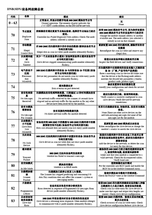
1常见问题:(1)共模电压引起的问题现象:●正常操作时电源末端附近的点不能通信●只有减少站点和主干线电缆长度才能通信●扫描器探测不到正确的适配器设备解决:●检查网络末端设备的通信连接有无问题●查看共模电压是否低于15V●拆除超载部分的设备●缩短超长部分的网络电缆●将电源朝超载部分的方向移动●拆除耗用网络电源的设备●增加第二个电源●将网络分为两个(2)总线故障现象:●站点操作时断时续(支线突然关闭)●LED或其他显示指示输出Bus off解决:●检查波特率的设置,只要有一个设备设置不对,就会影响到其他站点●替换怀疑有问题的设备,重检查波特率●检查操作时断时续的站点,电缆或连接头是否松动、弯曲或扭曲,并重检查波特率(3)总线信息流问题现象:●站点停止通信●设备出现超时解决:●检查扫描器组态,确定扫描速率是正确的内扫描时间太短会引起设备超时内扫描时间太长降低了带宽利用率●检查COS设备是否过多地占用带宽●对设备的运行时间进行约束,或把设备改成Poll Cyclic或Storbe通信形式●检查带宽过多或比平均值高出很多的设站点(4)总线电源问题现象:●正常操作时电源末端的设备不通信●只有减少站点或主干线长度时网络才能通信解决:●检查站点上的网络电源电压●检查站点上的共模电压●检查去用网络电源的输出设备●检查网络电缆通路靠近电压或射频信号而引起的冲突●用示波器检查电源波形●检查操作时断时续的站点、电缆或连接头是否松动、弯曲或扭曲,并检查峰值电压(5)屏蔽线电压问题现象:●操作时断时续的站点●扫描器探测不到正确组态的适配器设备解决:●检查屏蔽电压●检查V-端的漂移电压或屏蔽线的连接●检查是否连接松散●确认只要屏蔽线和V-一起连接到接地端2故障代码和LED状态(1)扫描器故障代码扫描器的屏幕显示的工作状态和故障代码,如果扫描器与摸个从设备的故障,则在故障代码之后给出从设备的站号(2)从设备LED状态从设备的LED状态表达了设备的状态。
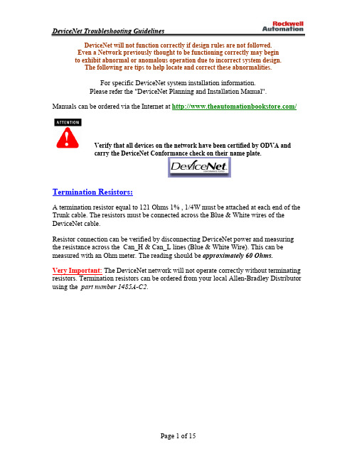
DeviceNet的故障排除DeviceNet的将无法正常工作,如果不遵循的设计规则。
即使是以前认为的网络要正确运作可能会开始表现出异常的运作不正常或因不正确的系统设计。
下面的提示,以帮助查找和纠正这些异常。
对于特定的DeviceNet系统的安装信息。
请参见出版物的DN - 6.7.2题为“DeviceNet的规划和安装手册”。
手册可以下令在互联网上通过自动化书店““或您当地的Allen - Bradley分销商或销售办事处。
终端电阻:终止121欧姆的电阻等于1%,碳膜必须附加在每个月底的干线电缆。
The 电阻必须跨接电线的DeviceNet电缆的蓝与白。
电阻连接可以验证DeviceNet电源断开,并通过测量电阻在Can_H&Can_L线(蓝与白线)。
该读数应大约60欧姆。
重要事项:在DeviceNet网络不会正确操作电阻不终止。
终止电阻可从网上订购当地的Allen - Bradley经销商使用零件编号1485A -C2的。
网络接地:在DeviceNet电缆必须接地的位置只有一个。
这应该是做最接近的中心网络。
连接网络屏蔽和排水管线到接地使用#8 AWG导线多达最大3米)在length.Also(10英尺连接的V -导体的网络干线电缆(黑线)和直流接地的接地连接的电源这一点。
电源:DeviceNet的需要24V直流。
使用额定24V直流电源(+ / - 1%)。
确保电力供应它自己的电流限制保护。
熔断器保护提供电缆系统为每个段。
DeviceNet的需要一个电源输出电压范围内有5%上升到其额定一时间小于250毫秒。
The 电源必须正确地提供各种大小的动力装置,其所需。
重要事项:应使用电源供电DeviceNet网络only.When多个电源供应需要,验证了V +连接用品打破之间。
请参阅“DeviceNet的规划和安装程序手册“的更具体的安装。
检查安装系统的设计漫步在网络如果能够确定实际的布局。
(使网络示意图)检查节点数检查长度累计下降检查个体长度下降检查支下降的长度检查总干线长度,包括附近的长长的跌落完检查终止位置,测量的终结检查电源线的长度和压力表检查一,且只有一个地球地面的V -和盾牌打破框架组合shield/V-连接到地面,并验证> 1.0兆欧到帧地检查一个且只有一个V型屏蔽连接打破连接电源shield/V-在和验证> 1.0兆欧盾至V与24V直流关闭检查的CAN短裤的CAN和/或+来屏蔽或V -验证与一欧姆表检查的长度和规范的接地连接检查总用电负荷及分布点检查电源检查干线和降电流限制检查类型和长度)的电缆(主干力量的大小将进入测量中的24V电源和网络两端考虑抽查示波器噪声功率为一24伏直流电源用于DeviceNet网络必须为DeviceNet网络而已。
检查接线检查接线盒穿着铅检查接口是否拧紧在一起检查腺体拧紧检查是否有异物磁带,广播电视大学等),腺(电检查节点不接触极热或极冷的表面检查电缆是否远离电源线几英寸检查电缆没有披上电磁铁电动马达,继电器,接触器或检查电缆没有约束,以连接器上的过度紧张的地方威格尔连接挑起间歇性故障检查扫描仪配置验证扫描列表波特率节点地址系列/修改的1747/1771-SDN扫描仪检查节点降24V电源,重新启动并复位初始化网络扫描仪检查扫描仪显示的代码,以确定问题的节点。
(参考手册中的这些化学需氧量供需为一个描述胚胎干)在有问题的节点闪烁绿色表示该节点没有被分配的扫描仪检查节点在扫描列表检查扫描仪是不是总线关闭检查连接超时闪烁的红色表示没有沟通检查所有节点的电源失踪检查所有其他节点都断开检查节点波特率(波特率错误并不总是导致巴斯关闭)检查扫描仪,如果是节点总线关闭(代码91)的通讯连接,然后与已超时。
回收24V电源,然后重新扫描仪。
如果扫描仪云巴士再次起飞,但问题是一些组合有缺陷的节点节点波特率坏的拓扑结构接触不良坏扫描仪坏电源接地不良坏电噪声在红色上固体光功率是指两个节点具有相同的地址分配方式固红继率总线关闭检查波特-如果问题仍然存在,替换节点(一定要设置地址和更换节点波特率上)若症状持续取代T -塔检查的拓扑结构检查电源分析仪与示波器或电源噪声干扰你需要记住的按复位按钮,扫描仪不重置网络骑自行车机架功率不重置网络当使用DeviceLink条件总线关闭(纯红色)只能清除循环的24V电源骑自行车网络接通会导致扫描仪去总线关闭9000的DeviceNet总线关闭(纯红色)条件可用于清除循环的24V电源或按程序按钮几秒钟必须特别小心给予利率任务设置初始地址和波特率,因为一个不正确或不正确的节点地址波特率将导致其他节点似乎是坏的(纯红色)。
如果扫描仪是总线关闭(代码91),节点将不会重新分配(闪烁的绿色或红色),即使它们运行正常DeviceNet的经理和1770 -科威特消防局可用于识别网络上的运作节点。
如果一个节点出现)巴士优惠(纯红色 DeviceLink,而被替换,但是她总线关闭,问题是不是节点,而是拓扑结构设置的地址或波特率或网络范围内的问题有关,接地,电气噪音或一间歇性的节点更多疑难排解提示试图分辨,尽快,媒体问题的设备问题从。
尽量减少系统的最小尺寸仍然展品的问题。
这可通过删除节点,滴,水龙头,或树干长度的。
使用替代排除在可能的事情了,但要小心!真实个案:产品A的工程与产品B和C不与产品我们的结论是,问题C是与产品-错误!问题是与产品A,产品C是运行正常,但正好是容易受故障该产品A不要以为到了!如果您怀疑媒体的问题,检查始终是一个良好的开端。
验证长度,拓扑结构,正确的终止(非常重要)。
最重要的是检查连接。
打开或短裤可能是最大的问题。
在总线空闲(没有交通)电压可以显示的问题。
CAN_L andCAN_H应约2.5至3.0伏特相对于V -。
如果有交通,CAN_L会有点低,CAN_H 高一点。
使用欧姆表检查之间的电阻CAN_H and空闲时CAN_L。
这应该是60欧姆(二120并联欧姆终端)。
此值可低至50欧姆如果有很多附加的节点。
确保所有电线有良好附着在适当的地方。
采用V +水平,相对于V -时,应始终在11到25伏。
一个常见的问题是人遇到过的节点地址设置不正确的波特率和。
始终验证节点地址和波特率网络上,然后再安装上。
并尽量不要改变一个节点的波特率,而在网络上。
做波特在一个地方所有的变化只连接点。
接地回路尝试此之前只有一个盾牌,确保一方的接地。
使用示波器,以确定是否有接地回路中的谐波在system.You不应该看到60 Hz 或你的信号。
假设你使用直流耦合应该看到在示波器上你....2.8 VDC信号抵消都Can_High及Can_Low无正弦,即60赫兹的组件。
DeviceNet电缆黑色通用- COM的蓝-信号低- CAN_L无绝缘盾白信号高- CAN_H红电源-直流+绿色机箱接地-接地DeviceNet连接器检查向下连接器与键槽指点。
引脚数起在最右边的脚键槽(1),继续逆时针旋转,直到你达到引脚(5)。
PIN码1盾构绿色引脚2伏+红引脚3COM的黑色引脚4CAN_HIGH白密码5CAN_LOW蓝DeviceNet扫描仪状态/错误代码在双色(绿色 / 红色)模块的状态指示灯显示设备状态。
这表明该设备是否有电并且运作正常。
指示灯然后采取这一行动------------------|---------------------------------------------|-----------------------|关|存在的设备没有通电。
|接通电源。
| |绿|该设备在正常运行条件。
|什么都不做。
| |闪烁绿色|该设备需要配置。
|配置设备。
闪烁的红色|有一个无效的配置。
|验证DIP开关| |设置。
| |检查组态| |设置。
| |红|该器件具有一个不可恢复的故障。
|更换模块。
------------------|---------------------------------------------|-----------------------|该网络是一个双色状态指示灯(绿色/红色)领导。
下表提供故障排除链接信息沟通。
指标是则表明采取这项行动-------------|-----------------------------|--------------------|-----------------------|关|设备没有权力或|该频道|电扫描仪,|通道已禁用|为残疾|提供网络力量|通讯由于关闭巴士| DeviceNet的|频道,并|条件,网络损失|通信|肯定通道|电源,或已| |启用中|故意禁用。
| |扫描仪配置| | |表和模块命令| | |字。
-------------|-----------------------------|--------------------|-----------------------|闪烁|两位数的数字显示|该频道|配置扫描列表绿|频道的指示|启用,但尚未|频道表|错误代码,提供更多|通信|添加设备|信息关于|发生||条件的通道| |-------------|-----------------------------|--------------------|-----------------------|纯绿色 |有正常的操作|从器件在所有|| |扫描列表表|| |是沟通|无为| |通常使用|| |扫描仪|-------------|-----------------------------|--------------------|-----------------------|纯红色|通信通道|扫描仪可能会|复位模块。
如果|有failed.The两位数|缺陷。
|失败继续下去,|用于数字显示器| |更换模块。
|频道显示错误| ||代码,提供更多| ||资讯的| ||条件的通道| |-------------|-----------------------------|--------------------|-----------------------|闪烁的红色 |两位数的数字显示|一体的,至少|检查失败|为通道显示|在从设备|设备和检查|错误代码,提供更多|扫描仪的扫描列表|扫描列表表|的信息|表格未能|的准确性。
|条件的通道。
|沟通与|| | scanner.The网络|| |出现了故障。
|-------------|-----------------------------|--------------------|-----------------------|您1747/1771-SDN扫描器模块都有一个节点的地址/状态指示灯,使用数字显示以表明您的模块的诊断信息。