4500系列交换机白皮书
- 格式:pdf
- 大小:372.93 KB
- 文档页数:4
数据中心交换机 buffer 需求分析白皮书目录1引言 (3)1.1DC 的网络性能要求 (3)1.2国内OTT 厂商对设备Buffer 的困惑 (4)1.3白皮书的目标 (4)2Buffer 需求的经典理论 (5)2.11BDP 理论 (5)2.2Nick Mckeown 理论 (6)2.3经典理论的适用性 (6)3基于尾丢弃的buffer 需求 (9)3.1丢包的影响 (9)3.1.2丢包对带宽利用率的影响 (9)3.1.3丢包对FCT 的影响 (12)3.2大buffer 的作用 (13)3.2.1吸收突发,减少丢包,保护吞吐 (13)3.2.2带宽分配均匀 (14)3.2.3优化FCT (15)3.3DC 内哪需要大buffer (15)3.4需要多大buffer (17)3.5带宽升级后,buffer 需求的变化 (19)3.6 小结 (19)4基于ECN 的buffer 需求 (21)4.1ECN 的作用 (21)4.2ECN 水线设置 (23)4.3基于ECN 的buffer 需要多大 (24)5基于大小流区分调度的buffer 需求 (27)5.1大小流差异化调度 (27)5.2大小流差异化调度如何实现大buffer 相当甚至更优的性能 (27)5.3基于大小流差异化调度的buffer 需要多大 (28)6 总结 (28)7 缩略语 (29)1 引言1.1DC 的网络性能要求近几年,大数据、云计算、社交网络、物联网等应用和服务高速发展,DC 已经成为承载这些服务的重要基础设施。
随着信息化水平的提高,移动互联网产业快速发展,尤其是视频、网络直播、游戏等行业的爆发式增长,用户对访问体验提出了更高的要求;云计算技术的广泛应用带动数据存储规模、计算能力以及网络流量的大幅增加;此外,物联网、智慧城市以及人工智能的发展也都对DC提出了更多的诉求。
为了满足不断增长的网络需求,DC 内的网络性能要求主要体现在:•低时延。

思科6500与4500区别思科Catalyst 6500交换机是针对大型企业核心网络/数据中心建设所需要的高端口密度、高转发性能、高级智能特性而开发的,其机箱、电源、内部交换架构均是依据大型企业核心网络和数据中心的应用特点而特别优化设计的。
而思科Catalyst 4500系列产品则不同,它通常用作中小型企业(SMB)的核心设备或大型网络的汇聚层设备。
6500与4500的具体区别主要体现在如下几个方面:1、性能:6500系列交换机的交换能力可达到720Gbps(每槽位40G),IPV4数据包吞吐量450Mpps (基于硬件);而且MAC地址表的容量能够达到64K,IPV4路由表最大达到1M;而4500交换机即使采用思科最新推出的Supervisor Engine 6-E 引擎,其交换能力最大也只能达到320Gbps(每槽位最大24G),IPV4包转发率也只能达到250Mpps,其整体性能与6500E相比相差甚远。
2、硬件架构:6500E的交换架构为无阻塞的交换矩阵架构(Switch Fabric),通过交换矩阵架构,交换机各插槽的板卡能够实现点到点的分布式转发,数据交换效率大大提高;而4500E采用的仍然是传统的总线架构(Classic BUS),交换机各插槽板卡间的通信需要经过一条共享带宽的总线,由交换机控制引擎进行统一调度,它的缺点在于整个交换机的路由性能受限于总线带宽和控制引擎,数据交换能力低下,而且加重了交换机控制引擎的负担。
这种传统的总线架构正逐步被先进的交换矩阵架构所取代。
此外,4500E系列交换机中仅有4507R-E和4510R-E支持双引擎,而6500E系列交换机中的所有型号均支持冗余的双引擎。
3、数据中心应用关键特性VSS:为了强化交换网络中的核心层设备,Cisco推出了VSS技术(虚拟交换技术),VSS的功能是将多台交换机虚拟成单台交换机,在配置VSS之后,不仅可以提高核心交换机的易操作性,同时还能实现核心层的故障恢复率,从而提供不间断通信能力。

C H A P T E R54-1Software Configuration Guide—Release IOS XE 3.3.0SG and IOS 15.1(1)SGOL-25340-0154Configuring Storm ControlThis chapter describes how to configure port-based traffic control on the Catalyst 4500 series switch.This chapter consists of these sections:•About Storm Control, page 54-1•Enabling Broadcast Storm Control, page 54-3•Enabling Multicast Storm Control, page 54-4•Disabling Broadcast Storm Control, page 54-5•Disabling Multicast Storm Control, page 54-5•Displaying Storm Control, page 54-6NoteFor complete syntax and usage information for the switch commands used in this chapter, first look at the Cisco Catalyst 4500 Series Switch Command Reference and related publications at this location:/en/US/products//hw/switches/ps4324/index.htmlIf the command is not found in the Catalyst 4500 Series Switch Command Reference, it will be found in the larger Cisco IOS library. Refer to the Cisco IOS Command Reference and related publications at this location:/en/US/products/ps6350/index.htmlAbout Storm ControlThis section contains the following subsections:•Hardware-Based Storm Control Implementation, page 54-2•Software-Based Storm Control Implementation, page 54-2Storm control prevents LAN interfaces from being disrupted by a broadcast storm. A broadcast storm occurs when broadcast packets flood the subnet, creating excessive traffic and degrading network performance. Errors in the protocol-stack implementation or in the network configuration can cause a broadcast storm.54-2Software Configuration Guide—Release IOS XE 3.3.0SG and IOS 15.1(1)SGOL-25340-01Chapter 54 Configuring Storm ControlAbout Storm ControlSoftware Configuration Guide—Release IOS XE 3.3.0SG and IOS 15.1(1)SGOL-25340-01Chapter 54 Configuring Storm ControlEnabling Broadcast Storm ControlEnabling Broadcast Storm ControlTo enable storm control, perform this task:The following example shows how to enable storm control on interface:Switch# configure terminalEnter configuration commands, one per line. End with CNTL/Z.Switch(config)# interface fa3/1Switch(config-if)# storm-control broadcast level 50Switch(config-if)# endSwitch# show storm-controlInterface Filter State Broadcast Multicast Level --------- ------------- --------- --------- -----Fi3/1 Forwarding Enabled Disabled 50.00% Switch# show int fa2/1 capabilities FastEthernet2/1Model: WS-X4148-RJ45V-RJ-45 Type: 10/100BaseTX Speed: 10,100,autoCommandPurposeStep 1Switch# configure terminalEnters global configuration mode.Step 2Switch(config)# interface interface-id Enters interface configuration mode and enter the port to configure.Step 3Switch(config-if)# storm-control broadcast level [high level ]Configures broadcast storm control.Specifies the upper threshold levels for broadcast traffic. The storm control action occurs when traffic utilization reaches this level.(Optional) Specifies the falling threshold level. The normaltransmission restarts (if the action is filtering) when traffic drops below this level for interfaces that support software-based suppression.NoteFor ports that perform hardware-based suppression, the lower threshold is ignored.NoteFor the Catalyst 4500-X Series Switch, on ports operating at 1Gigabit, thresholds less than 0.02% are not supported.Step 4Switch(config-if)# storm-control action {shutdown | trap }Specifies the action to be taken when a storm is detected.The default is to filter out the broadcast traffic and not to send out traps.The shutdown keyword sets the port to error-disable state during a storm. If the recover interval is not set, the port remains in shutdown state.Step 5Switch(config-if)# exit Returns to configuration mode.Step 6Switch(config)# endReturns to privileged EXEC mode.Step 7Switch# show storm-control [interface ] broadcastDisplays the number of packets suppressed.Step 8Switch# copy running-config startup-config(Optional) Saves your entries in the configuration file.Software Configuration Guide—Release IOS XE 3.3.0SG and IOS 15.1(1)SGOL-25340-01Chapter 54 Configuring Storm ControlEnabling Multicast Storm ControlDuplex: half,full,auto Auto-MDIX: noTrunk encap. type: 802.1QTrunk mode: on,off,desirable,nonegotiate Channel: yesBroadcast suppression: percentage(0-100), hw Multicast suppression: percentage(0-100), hw Flowcontrol: rx-(none),tx-(none) VLAN Membership: static, dynamic Fast Start: yes CoS rewrite: yes ToS rewrite: yesInline power: yes (Cisco Voice Protocol) SPAN: source/destination UDLD: yes Link Debounce: no Link Debounce Time: no Port Security: yes Dot1x: yesMaximum MTU: 1552 bytes (Baby Giants) Multiple Media Types: no Diagnostic Monitoring: N/AEnabling Multicast Storm ControlCatalyst 4900M, Catalyst 4948E, Supervisor Engine 6-E, Supervisor Engine 6L-E, Supervisor Engine 7-E, and Supervisor Engine 7L-E support per-interface multicast suppression, which allows you to subject incoming multicast and broadcast traffic to interface-level suppression.NoteMulticast and broadcast suppression share a common threshold per interface. Multicast suppression takes effect only if broadcast suppression is enabled. Disabling broadcast suppression on an interface also disables multicast suppression.To enable multicast suppression, perform this task:The following example shows how to enable multicast suppression on ports that have broadcast suppression already enabled:Switch# configure terminalEnter configuration commands, one per line. End with CNTL/Z.Switch(config)# int fa3/1Switch(config-if)# storm-control broadcast include multicastCommandPurposeStep 1Switch# configure terminalEnters global configuration mode.Step 2Switch(config)# interface interface-id Enters interface configuration mode and enter the port to configure.Step 3Switch(config-if)# storm-control broadcast include multicast Enables multicast suppression.Step 4Switch(config-if)# exit Returns to configuration mode.Step 5Switch(config)# endReturns to privileged EXEC mode.Step 6Switch# show storm-controlVerifies the configuration.Software Configuration Guide—Release IOS XE 3.3.0SG and IOS 15.1(1)SGOL-25340-01Chapter 54 Configuring Storm ControlDisabling Broadcast Storm ControlSwitch(config-if)# end Switch#Switch# show storm-controlInterface Filter State Broadcast Multicast Level --------- ------------- --------- --------- -----Fi3/1 Forwarding Enabled Enabled 50.00%Disabling Broadcast Storm ControlTo disable storm control, perform this task:The following example shows how to disable storm control on interface.Switch# configure terminalEnter configuration commands, one per line. End with CNTL/Z.Switch(config)# int fa3/1Switch(config-if)# no storm-control broadcast level Switch(config-if)# endSwitch# show storm-controlInterface Filter State Broadcast Multicast Level --------- ------------- --------- --------- -----Switch#Disabling Multicast Storm ControlTo disable multicast suppression, perform this task:CommandPurposeStep 1Switch# configure terminalEnters global configuration mode.Step 2Switch(config)# interface interface-id Enters interface configuration mode and enter the port to configure.Step 3Switch(config-if)# no storm-control broadcast levelDisables port storm control.Step 4Switch(config-if)# no storm-control action {shutdown | trap }Disables the specified storm control action and returns to default filter action.Step 5Switch(config-if)# exit Returns to configuration mode.Step 6Switch(config)# endReturns to privileged EXEC mode.Step 7Switch# show storm-control broadcast Verifies your entries.Step 8Switch# copy running-config startup-config(Optional) Saves your entries in the configuration file.CommandPurposeStep 1Switch# configure terminalEnters global configuration mode.Step 2Switch(config)# [no ] storm-control broadcast include multicastEnables and disables multicast suppression.Step 3Switch(config-if)# no storm-control broadcast levelDisables port storm control (broadcast and multicast).Chapter54 Configuring Storm Control Displaying Storm ControlCommand PurposeStep4Switch(config-if)# end Returns to configuration mode.Step5Switch(config)# end Returns to privileged EXEC mode.Displaying Storm ControlNote Use the show interface capabilities command to determine the mode in which storm control is supported on an interface.The following example shows an interface that supports broadcast suppression in software (sw):Switch# show int fa2/1 capabilitiesFastEthernet2/1Model: WS-X4148-RJ45V-RJ-45Type: 10/100BaseTXSpeed: 10,100,autoDuplex: half,full,autoAuto-MDIX: noTrunk encap. type: 802.1QTrunk mode: on,off,desirable,nonegotiateChannel: yesBroadcast suppression: percentage(0-100), hwMulticast suppression: percentage(0-100), hwFlowcontrol: rx-(none),tx-(none)VLAN Membership: static, dynamicFast Start: yesCoS rewrite: yesToS rewrite: yesInline power: yes (Cisco Voice Protocol)SPAN: source/destinationUDLD: yesLink Debounce: noLink Debounce Time: noPort Security: yesDot1x: yesMaximum MTU: 1552 bytes (Baby Giants)Multiple Media Types: noDiagnostic Monitoring: N/ANote Use the show interfaces counters storm-control command to display a count of discarded packets.Switch# show interfaces counters storm-controlPort Broadcast Multicast Level TotalSuppressedPacketsFa2/1 Enabled Disabled 10.00% 46516510Gi3/1 Enabled Enabled 50.00% 0Switch# show storm-controlInterface Filter State Broadcast Multicast Level--------- ------------- --------- --------- -----Fa2/1 Blocking Enabled Disabled 10.00%Gi3/1 Link Down Enabled Enabled 50.00%Software Configuration Guide—Release IOS XE 3.3.0SG and IOS 15.1(1)SGOL-25340-01。

华为全系列数据通信产品白皮书第一部分:引言(200字)数据通信产品在现代社会中扮演着至关重要的角色,它们是连接世界的桥梁,促进了信息的传递和交流。
华为作为全球领先的通信技术解决方案提供商,为满足客户需求,推出了一系列高质量的数据通信产品。
本白皮书旨在介绍华为全系列数据通信产品的技术特点、应用场景和优势,帮助用户更好地了解和选择适合自己的产品。
第二部分:产品概述(200字)华为全系列数据通信产品包括路由器、交换机、光纤传输设备等多个种类。
这些产品具备高度的稳定性、可靠性和安全性,能够保证数据传输的质量和效率。
华为路由器是业界领先的产品之一,支持高速连接,稳定运行和智能优化。
交换机则提供灵活的网络管理和控制功能,适用于各种不同规模和需求的环境。
光纤传输设备则可以实现高容量和长距离的数据传送,特别适用于电信、金融和大型企业等行业。
第三部分:技术特点(300字)华为全系列数据通信产品具备一系列重要的技术特点。
首先,这些产品都采用了先进的硬件和软件技术,能够实现高效的数据处理和传输。
其次,华为产品支持灵活的网络配置和管理,可以根据实际需求进行定制和扩展。
同时,华为产品还具备高度的安全性,采用了先进的加密和认证技术,保障了数据的机密性和完整性。
此外,华为产品还支持智能化的运维和管理,通过数据分析和优化,提高了网络的性能和稳定性。
第四部分:应用场景(300字)华为全系列数据通信产品广泛应用于各个领域。
它们可以满足不同规模和需求的数据通信需求,适用于运营商、企业和个人用户等不同类型的客户。
在运营商领域,华为产品可以构建高速、稳定和安全的通信网络,支撑运营商的业务和服务。
在企业领域,华为产品可以实现灵活的网络管理和控制,提供高效的数据传输和存储解决方案。
对于个人用户来说,华为产品可以提供高速的网络连接和智能的家庭网络管理,满足各种娱乐和生活需求。
第五部分:产品优势(200字)华为全系列数据通信产品具备多个优势。
首先,它们拥有领先的技术和创新能力,能够满足不断变化的市场需求。
Junos Pulse Secure Access Service Getting Started Guide for SA Series2500,4500 and6500SSL VPN AppliancesRelease7.2Published:2012-03-20Part Number:,Revision1Juniper Networks,Inc.1194North Mathilda AvenueSunnyvale,California94089USA408-745-2000This product includes the Envoy SNMP Engine,developed by Epilogue T echnology,an Integrated Systems Company.Copyright©1986-1997, Epilogue T echnology Corporation.All rights reserved.This program and its documentation were developed at private expense,and no part of them is in the public domain.This product includes memory allocation software developed by Mark Moraes,copyright©1988,1989,1993,University of T oronto.This product includes FreeBSD software developed by the University of California,Berkeley,and its contributors.All of the documentation and software included in the4.4BSD and4.4BSD-Lite Releases is copyrighted by the Regents of the University of California.Copyright©1979,1980,1983,1986,1988,1989,1991,1992,1993,1994.The Regents of the University of California.All rights reserved.GateD software copyright©1995,the Regents of the University.All rights reserved.Gate Daemon was originated and developed through release3.0by Cornell University and its collaborators.Gated is based on Kirton’s EGP,UC Berkeley’s routing daemon(routed),and DCN’s HELLO routing protocol.Development of Gated has been supported in part by the National Science Foundation.Portions of the GateD software copyright©1988,Regents of the University of California.All rights reserved.Portions of the GateD software copyright©1991,D. L.S.Associates.This product includes software developed by Maker Communications,Inc.,copyright©1996,1997,Maker Communications,Inc.Juniper Networks,Junos,Steel-Belted Radius,NetScreen,and ScreenOS are registered trademarks of Juniper Networks,Inc.in the United States and other countries.The Juniper Networks Logo,the Junos logo,and JunosE are trademarks of Juniper Networks,Inc.All other trademarks,service marks,registered trademarks,or registered service marks are the property of their respective owners.Juniper Networks assumes no responsibility for any inaccuracies in this document.Juniper Networks reserves the right to change,modify, transfer,or otherwise revise this publication without notice.Products made or sold by Juniper Networks or components thereof might be covered by one or more of the following patents that are owned by or licensed to Juniper Networks:U.S.Patent Nos.5,473,599,5,905,725,5,909,440,6,192,051,6,333,650,6,359,479,6,406,312, 6,429,706,6,459,579,6,493,347,6,538,518,6,538,899,6,552,918,6,567,902,6,578,186,and6,590,785.Junos Pulse Secure Access Service Getting Started Guide for SA Series2500,4500and6500SSL VPN AppliancesRevision History2010—Revised for SA release7.0.The information in this document is current as of the date on the title page.END USER LICENSE AGREEMENTThe Juniper Networks product that is the subject of this technical documentation consists of(or is intended for use with)Juniper Networks e of such software is subject to the terms and conditions of the End User License Agreement(“EULA”)posted at/support/eula.html.By downloading,installing or using such software,you agree to the terms and conditions of that EULA.Abbreviated T able of ContentsAbout This Guide (ix)Part1Installation and Start-Up Procedures for SA Series2500,4500and6500AppliancesChapter1Getting Started With the SA Series2500,4500and6500SSL VPNAppliances (3)Part2IndexIndex (11)Getting Started Guide for SA Series2500,4500and6500AppliancesT able of ContentsAbout This Guide (ix)Related Documentation (ix)Document Conventions (ix)Requesting T echnical Support (x)Self-Help Online T ools and Resources (x)Opening a Case with JTAC (x)Part1Installation and Start-Up Procedures for SA Series2500,4500and6500AppliancesChapter1Getting Started With the SA Series2500,4500and6500SSL VPNAppliances (3)Step1:Installing the Hardware (3)Device Status LED Behavior (4)Ethernet Port LED Behavior (5)Bonding Ports (5)Step2:Performing Basic Setup (5)Step3:Licensing and Configuring Your Secure Access (7)Part2IndexIndex (11)Getting Started Guide for SA Series2500,4500and6500AppliancesList of T ablesAbout This Guide (ix)T able1:Notice Icons (ix)Part1Installation and Start-Up Procedures for SA Series2500,4500and6500AppliancesChapter1Getting Started With the SA Series2500,4500and6500SSL VPNAppliances (3)T able2:Device Status LEDs (4)T able3:4-Port Copper Gigabit Ethernet LEDs(available on SA4500and SA6500) (5)Getting Started Guide for SA Series2500,4500and6500AppliancesAbout This Guide•Related Documentation on page ix•Document Conventions on page ix•Requesting T echnical Support on page xRelated Documentation•T o download a PDF version of the Secure Access Administration Guide,go to the SecureAccess/SSL VPN Product Documentation page of the Juniper Networks CustomerSupport Center.•For information about the changes that Secure Access clients make to client computers, including installed files and registry changes,and for information about the rightsrequired to install and run Secure Access clients,refer to the Client-side Changes Guide.•For information on how to personalize the look-and-feel of the pre-authentication,password management,and Secure Meeting pages that Secure Access displays toend-users and administrators,refer to the Custom Sign-In Pages Solution Guide. Document ConventionsT able1on page ix defines notice icons used in this guide.Table1:Notice IconsInformational noteIndicates important features or instructions.WarningAlerts you to the risk of personal injury or death.Getting Started Guide for SA Series2500,4500and6500AppliancesRequesting Technical SupportT echnical product support is available through the Juniper Networks T echnical AssistanceCenter(JTAC).If you are a customer with an active J-Care or JNASC support contract,or are covered under warranty,and need post-sales technical support,you can accessour tools and resources online or open a case with JTAC.•JTAC policies—For a complete understanding of our JTAC procedures and policies,review the JTAC User Guide located at/us/en/local/pdf/resource-guides/7100059-en.pdf.•Product warranties—For product warranty information,visit/support/warranty/.•JTAC hours of operation—The JTAC centers have resources available24hours a day,7days a week,365days a year.Self-Help Online Tools and ResourcesFor quick and easy problem resolution,Juniper Networks has designed an onlineself-service portal called the Customer Support Center(CSC)that provides you with thefollowing features:•Find CSC offerings:/customers/support/•Search for known bugs:/kb/•Find product documentation:/techpubs/•Find solutions and answer questions using our Knowledge Base:/•Download the latest versions of software and review release notes:/customers/csc/software/•Search technical bulletins for relevant hardware and software notifications:https:///alerts/•Join and participate in the Juniper Networks Community Forum:/company/communities/•Open a case online in the CSC Case Management tool:/cm/T o verify service entitlement by product serial number,use our Serial Number Entitlement(SNE)T ool:https:///SerialNumberEntitlementSearch/Opening a Case with JTACYou can open a case with JTAC on the Web or by telephone.•Use the Case Management tool in the CSC at /cm/.•Call1-888-314-JTAC(1-888-314-5822toll-free in the USA,Canada,and Mexico).For international or direct-dial options in countries without toll-free numbers,see/support/requesting-support.html.PART1Installation and Start-Up Procedures for SA Series2500,4500and6500 Appliances•Getting Started With the SA Series2500,4500and6500SSL VPNAppliances on page3Getting Started Guide for SA Series2500,4500and6500AppliancesCHAPTER1Getting Started With the SA Series2500, 4500and6500SSL VPN AppliancesThank you for choosing the Juniper Networks SA Series SSL VPN appliance.You caninstall Secure Access and start configuring your system using the following easy steps:NOTE:After installing and setting up your Secure Access,refer to the InitialConfiguration task guide in the administrator Web console to install the mostcurrent Secure Access OS service package,license your Secure Accessappliance,and create a test user to verify user accessibility.To test initialset-up and continue configuring your Secure Access,refer to the“Gettingstarted”section of the Juniper Networks Secure Access Administration Guide.We recommend that you install the Secure Access appliance on your LAN to ensure thatit can communicate with the appropriate resources,like authentication servers,DNSservers,internal Web servers via HTTP/HTTPS,external Web sites via HTTP/HTTPS(optional),Windows file servers(optional),NFS file servers(optional),and client/serverapplications(optional).NOTE:If you decide to install your Secure Access appliance in your DMZ,ensure that the Secure Access appliance can connect to these internalresources.•Step1:Installing the Hardware on page3•Step2:Performing Basic Setup on page5•Step3:Licensing and Configuring Your Secure Access on page7Step1:Installing the HardwareThe Secure Access2500,4500and6500ship with mounting ears and mid-mounts.The Secure Access6500includes rear mounting rails for use in a four-post mountingrack.We recommend you use the rear mounting rails when installing the Secure Access6500in a rack.If you require an additional mounting kit,contact Juniper Networks.Getting Started Guide for SA Series2500,4500and6500AppliancesNext,connect the included cables and power on the Secure Access appliance followingthese steps:1.On the front panel:a.Connect an Ethernet cable from one of the Ethernet ports on the device to a Gigabitswitch port set to1000BaseTX.DO NOT use autoselect on either port.Once you apply power to the Secure Access device,the port uses two LEDs toindicate the connection status,which is described in“Ethernet Port LED Behavior”on page5.b.Plug the serial cable into the console port.2.On the rear panel,plug the power cord into the AC receptacle.There is no on/offswitch on Secure Access.Once you plug the power cord into the AC receptacle,SecureAccess powers up.Hardware installation is complete after you rack-mount the appliance and connect thepower,network,and serial cables.The next step is to connect to the appliance’s serialconsole as described in“Bonding Ports”on page5.Device Status LED BehaviorStartup takes approximately one minute to complete.If you want to turn the device offand on again,we recommend you wait a few seconds between shutting it down andpowering it back up.There are three device status LEDs located on the left-side of the front panel:•Power•Hard disk access•FaultT able2on page4lists the name,color,status,and description of each device statusLED.Table2:Device Status LEDsPOWERGreenDevice is not receiving powerOffOn SteadyDevice is receiving powerHARD DISK ACCESSYellowHard disk is idleOffBlinkingHard disk is being accessedFAULTRedDevice is operating normallyOffSlowPower supply faultblinkingChapter1:Getting Started With the SA Series2500,4500and6500SSL VPN Appliances Table2:Device Status LEDs(continued)Fast blinkingFan failureSolidThermal failureEthernet Port LED BehaviorThe Ethernet port LEDs show the status of each Ethernet port.Table3:4-Port Copper Gigabit Ethernet LEDs(available on SA4500andSA6500)Link/ActivityLinkGreenActivityBlinking greenLink SpeedOff10MbpsGreen100Mbps1GbpsYellowBonding PortsBy default,on the SA6500only,Secure Access uses bonding of the multiple ports toprovide failover protection.Bonding describes a technology for aggregating two physicalports into one logical group.Bonding two ports on Secure Access increases the failovercapabilities by automatically shifting traffic to the secondary port when the primary portfails.The SA6500appliance bonds ports as follows:•Internal port=Port0+Port1•External port=Port2+Port3Secure Access indicates in a message on the System>Network>Overview page whetheror not the failover functionality is enabled.Step2:Performing Basic SetupWhen you boot an unconfigured Secure Access appliance,you need to enter basic networkand machine information through the serial console to make the appliance accessibleto the network.After entering these settings,you can continue configuring the appliancethrough the administrator Web console.This section describes the required serial consolesetup and the tasks you need to perform when connecting to your Secure Accessappliance for the first time.T o perform basic setup:1.Configure a console terminal or terminal emulation utility running on a computer,suchas HyperT erminal,to use these serial connection parameters:•9600bits per second•8-bit No Parity(8N1)•1Stop Bit•No flow control2.Connect the terminal or laptop to the serial cable plugged in to the appliance’s consoleport and press Enter until you are prompted by the initialization script.3.Enter y to proceed and then y to accept the license terms(or r to read the licensefirst).4.Follow the directions in the serial console and enter the machine information for whichyou are prompted,including the:•IP address of the internal port(you configure the external port through the administrator Web console after initial configuration)•Network mask•Default gateway address•Primary DNS server address•Secondary DNS server address(optional)•Default DNS domain name(for example,)•WINS server name or address(optional)•Administrator username•Administrator password•Common machine name(for example,)•Organization name(for example,Acme Gizmo,Inc.)NOTE:Secure Access uses the common machine and organizationnames to create a self-signed digital certificate for use during productevaluation and initial setup.We strongly recommend that you import a signed digital certificate froma trusted certificate authority(CA)before deploying Secure Access forproduction use.For more information,refer to the“Certificates”chapter in the JuniperNetworks Secure Access Administration Guide.Getting Started Guide for SA Series2500,4500and6500AppliancesChapter1:Getting Started With the SA Series2500,4500and6500SSL VPN Appliances5.(FIPS only)The Secure Access FIPS appliances utilize FIPS140-2certified HardwareSecurity Modules(HSM)and require the following pieces of information to initializethe HSM and manage the HSM protected storage:•When prompted by the serial console,enter the security officer name and password.Save these credentials as they are required for creating new restore passwords andfor changing the security officer password.•Enter the key store restore or HSM master key backup password.•Enter the username and password for the HSM private key storage.Security officer names,usernames and key store names must adhere to the followingrequirements.RequirementDescriptionMinimum lengthAt least one character.Maximum length63characters for security officer names and user names.32characters forkeystore names.Alphanumeric,underscore(_),dash(-)and period(.)Valid charactersFirst characterMust be alphabetic.Passwords must be at least six characters.Three characters must be alphabetic andone character must be non-alphabetic.6.In a browser,enter the machine’s URL followed by“/admin”to access the administratorsign-in page.The URL is in the format:https://a.b.c.d/admin,where a.b.c.d is themachine IP address you entered in step4.When prompted with the security alert toproceed without a signed certificate,click Yes.When the administrator sign-in pageappears,you have successfully connected your Secure Access appliance to thenetwork.7.On the sign-in page,enter the administrator user name and password you created instep4and then click Sign In.The administrator Web console opens to theSystem>Status>Overview page.Step3:Licensing and Configuring Your Secure AccessAfter you install Secure Access and perform basic setup,you are ready to install the mostcurrent Secure Access OS service package,license Secure Access,verify accessibility,and complete the configuration process:•T o install the most current Secure Access OS service package,license your SecureAccess and create a test user to verify user accessibility,follow the task guide embeddedin the administrator Web console.•T o test initial set-up and continue configuring your Secure Access,refer to the“GettingStarted”section of the Juniper Networks Secure Access Administration Guide.Getting Started Guide for SA Series2500,4500and6500AppliancesPART2Index•Index on page11Getting Started Guide for SA Series2500,4500and6500AppliancesIndexCcustomer support (x)contacting JTAC (x)Ssupport,technical See technical supportTtechnical supportcontacting JTAC (x)Getting Started Guide for SA Series2500,4500and6500Appliances。
产品简介快速以太网和千兆位以太网线卡Cisco ® Catalyst ® 4500系列可扩展、模块化、高密度交换机提供了性能出众的第二、三、四层交换及智能服务,实现了网络控制和永续性。
这些交换机提供了多种快速以太网和千兆位以太网线卡,包括针对企业与商用交换解决方案的桌面、分支机构骨干和服务器,以及服务供应商城域以太网而优化的光纤及铜缆接口。
千兆位以太网线卡包括经济有效的高性能1000BASE-X 千兆位接口转换器(GBIC)、小型可插拔(SFP)千兆位以太网线卡和高密度10/100/1000BASE-T 三速自动检测、自动协商千兆位以太网线卡。
快速以太网线卡包括各种线速10/100、100-FX 、100BASE-LX10和100BASE-BX-D 密度。
以太网电源线卡Cisco Catalyst 4500系列提供了部署和运营标准以太网电源(PoE )网络互联所需的线卡、电源和附件。
当将一个符合IEEE 802.3af 标准或思科预标准上电设备连接到PoE 线卡时,PoE 在长达100米的标准第5类非屏蔽双绞线(UTP )电缆上提供了–48 VDC 电源。
IP 电话、无线基站、摄像机和其他符合IEEE 标准的端口连接设备无需墙壁电源,可使用Cisco Catalyst 4500系列PoE 线卡提供的电源。
此功能使网络管理员能集中控制电源,不必在天花板和其他可能安装上电设备的地方安装插座。
尽管所有如“PoE”、 “馈线电源”和“话音”电源及线卡等说法都是同义词,仍存在两个版本:思科预标准和IEEE 802.3af 标准版本。
每个Cisco Catalyst 4500系列机箱和PoE 电源都支持IEEE 802.3af 标准,而思科预标准电源实施则确保与现有思科上电设备向后兼容。
所有符合IEEE 802.3af 标准的线卡都可区分IEEE 或思科预标准上电设备和未上电网络接口卡(NIC);确保只在连接了适当设备时供电。
Migrating from Cisco Catalyst4500E to 9400 SeriesSwitchesGuide Cisco publicContentsIntroduction 3 Purpose of this guide 3 Why migrate? 3 Migration overview 4 Chassis hardware 4 Supervisor hardware 4 System default behaviors 5 Power redundancy 5 ROMMON and config-register 7 Operations 9 Software features 10 Cisco Catalyst 4500E Series platform-specific commands 12 Conclusion 12 Appendix A. IPDT/SISF 13IntroductionThe new Cisco® Catalyst® 9000 switching platform is the next generation in the legendary Cisco Catalyst family of enterprise LAN access, aggregation, and core switches. Within the Cisco Catalyst 9000 switching family, the 9400 Series switches are Cisco’s leading modular enterpris e switching access platform, built for security, Internet of Things (IoT), and cloud.Purpose of this guideThis document is intended to help network planners and engineers who are familiar with the Cisco Catalyst 4500E Series in deploying Cisco Catalyst 9400 Series Switches in the enterprise networking environment (Figure 1).Figure 1.Cisco Catalyst 4500E Series to Cisco Catalyst 9400 SeriesWhy migrate?The Cisco Catalyst 9400 Series Switches are Cisco’s leading modular enterprise switching access platform, built for security, IoT, and cloud. These switches form the foundational building block for Software-Defined Access (SD-Access) –Cisco’s leading enterprise architecture. The platform provides unparalleled investment protection with a chassis architecture that can support up to 9 Tbps of system bandwidth and unmatched power delivery for high-density IEEE 802.3BT (60W and 90W Power over Ethernet [PoE]). Redundancy is now the norm across the portfolio. The 9400 Series delivers state-of-the-art High Availability with capabilities such as uplink resiliency and N+1/N+N redundancy for power supplies. The platform is enterprise optimized with an innovative dual-serviceable fan tray design and side-to-side airflow and is closet friendly with ~16-inch depth.A single system can scale up to 384 access ports with your choice of 10G, 5G, and 2.5G multigigabit copper, 1G copper, Cisco UPOE+, Cisco UPOE and PoE+ options and up to 384 ports of 10G Fiber and 1G Fiber options. The platform also supports advanced routing and infrastructure services, SD-Access capabilities, and network system virtualization. These features enable optional placement of the platform in the core and aggregation layers of small to medium-sized campus environments.The Cisco Catalyst 9400 Series offers an industry-leading supervisor engine built for secure networks, IoT applications, next-generation mobility, and cloud adoption. Supervisor Engines are built with the latest Cisco Unified Access® Data Plane ASICs (UADP 3.0 on Supervisor 2/2XL and UADP 2.0XL on Supervisor 1/XL/XL-Y) future-proofed for next-generation technologies with its programmable pipeline, micro engine capabilities, and template-based configurable allocation of Layer 2, Layer 3, forwarding, Access Control Lists (ACLs), and Quality of Service (QoS) entries.Migration overviewThe Cisco Catalyst 9400 Series Switches retain the same centralized architecture as the 4500E Series, but with many new capabilities. This guide lists the different considerations when migrating from the 4500E Series to the 9400 Series.Chassis hardwareTable pares the chassis available on the Cisco Catalyst 4500E and 9400 Series.Supervisor hardwareThe Cisco Catalyst 9400 Supervisor Engines are based on Cisco’s UADP ASIC architecture an x86 CPU architecture. Supervisor Engines also provide options for additional internal and external storage, which enables the device to host containers and run third-party applications and scripts natively within the switch. Table 2 compares the hardware of the 4500E and 9400 Series.Table 2.Hardware comparisonSystem default behaviorsThe system default behaviors on the Cisco Catalyst 9400 Series are very similar to those of the 4500E Series. For example, interfaces are default in Layer 2 switch port mode, IP routing is enabled, the management interface is in a dedicated Virtual Routing and Forwarding (VRF) instance, and so on. However, there are also some differences.Control Plane Policing (CoPP): CoPP is enabled on the Cisco Catalyst 9400 Series, with default policing rates for different classes of traffic. These policing rates are optimized for a typical campus environment. The policing rates can be changed or disabled to meet the requirements of different application environments. On the Cisco Catalyst 4500E, CoPP is not enabled by default, but the system provides a macro to create the different classes, and the user can specify the policing rate for different classes.Link-status logging: The logging for link-status changes is on by default with the Cisco Catalyst 9400 Series, and the behavior can be changed per interface in the configuration. On the 4500E Series, the logging for link-status changes is off by default and can be changed globally. See Table 3.Table 3.Hardware comparisonPower redundancyThe Cisco Catalyst 9400 Series provides eight slots for the power supply in the 9407R and 9410R models, compared to two slots in the 4500E Series. Those eight power supply slots can be operated in the following three modes:1. Combined mode: This is the default mode. All power supply modules in the system are active andsharing power.2. N+1 redundant mode: N is the number of active power supply modules, and there is one powersupply module in standby mode. If any one of the active power supply modules fails, the standbypower supply becomes active.3. N+N redundant mode: In this mode, the system is configured with an equal number of active andstandby power supply modules.Table 4 compares the power capabilities of the Cisco Catalyst 4500E Series with those of the 9400 Series. Table 4.Power comparisonFor more details on power redundancy, please see the Environmental Monitoring and Power Management chapter of the System Management Configuration Guide.ROMMON and config-registerThe Cisco Catalyst 9400 Series uses the x86 CPU architecture to enable hosting containers and third-party applications. With this change, there are also changes in the ROMMON.Prompts and file systemIn ROMMON, the prompt on the Cisco Catalyst 9400 Series is “switch:” and the “flash:” is the memory partition for local storage. On the Cisco Catalyst 4500E Series, the prompt is “rommon>” and the “bootflash:” is the memory partition for local storage. Table 5 shows outputs in ROMMON from the 4500E and 9400 Series. Table 5.ROMMON outputsThe Cisco Catalyst 4500E Series uses the traditional “config-register” command in both Cisco IOS and ROMMON to control the booting behavior. The Cisco Catalyst 9400 Series uses a parallel set of commands in Cisco IOS XE Software, which creates the equivalent ROMMON variables. See Table 6.Table 6.Boot variablesBaud rateTable 7.Setting the baud rate“Break” processingAt the beginning of the bootup process, the user can use Ctrl+C to break out of the booting process and drop the system back into ROMMON if the break sequence is enabled. See Table 8.Table 8.“Break” processingTable 9.Ignoring the startup configurationOperationsInterface referenceThe Cisco Catalyst 4500E Series has two level of interface numbering:interface <Type><Slot#>/<Port#>The 9400 Series has three levels:interface <Type><Slot#>/<Bay#>/<Port#>As of release 16.6.2, the bay number is unused and is always 0. For example, Gigabit Ethernet port 1 on slot 1 is referenced as gi1/1 with the 4500E Series and as gi1/0/1 with the 9400 Series. See Table 10.Table 10.Interface numberingManagement interfaceThe management interface on the Cisco Catalyst 9400 Series is Gigabit Ethernet, which is much more capable than the Fast Ethernet on the 4500E Series. The management port on both platforms has its own VRF for separation of management traffic from normal data traffic. However, the name of the VRF for the management port is different between the 9400 Series and 4500E Series. Note also that the names of the VRFs are case sensitive. Table 11 lists the management port differences between the two platforms.Table 11.Management interface and VRFSoftware featuresFor details on the software features supported on the Cisco Catalyst 9400 Series, please use the feature navigator on . Some of the features behave differently on the 9400 Series compared to the 4500E Series. Following are some of these differences.System MTUOn the Cisco Catalyst 9400 Series, the global command “system mtu <1500-9216>” changes the MTU on all the interfaces within the system. On the Cisco Catalyst 4500E Series, the global command “system mtu <1500-1552>” sets the global baby gian t MTU for all interfaces. Both C9400 and 4500E Series also support per-interface MTU. The per-interface MTU command takes precedence. See Table 12.Table 12.Setting the system MTUHost tracking featureThe Cisco Catalyst 4500E Series supports IP Device Tracking (IPDT) for keeping track of connected hosts (association of MAC and IP addresses). In the Cisco Catalyst 9400 Series with the latest Cisco IOS XE release, the new Switch Integrated Security Features (SISF)-based IP device-tracking feature acts as a container policy that enables snooping and device-tracking features available with First Hop Security (FHS) in both IPv4 and IPv6, using IP-agnostic CLI commands. See Appendix A for more information on migrating from the IPDT CLI configuration to the new SISF-based device-tracking CLI configuration.Flexible NetFlowBoth the Cisco Catalyst 9400 Series and the Cisco Catalyst 4500E Series support Flexible NetFlow. Beside the scalability differences, there are a few configuration differences. They are listed in Table 13.Table 13.Flexible NetFlow differencesQuality of Service (QoS)The ASICs that power the Cisco Catalyst 4500E and 9400 Series are different, so there are some differences in QoS behaviors, as described below.Per-port per-VLAN QoS policyThe Cisco Catalyst 4500E Series provides the ability to configure service policy per VLAN under the trunk interface. The Cisco Catalyst 9400 Series supports this with the use of Hierarchical QoS. In this case, the parent policy consists of two different VLAN policies. Table 14 contains the per-port per- VLAN QoS configuration for both the 4500E and 9400 Series.Table 14.Per-port per-VLAN configurationCongestion avoidanceThe Cisco Catalyst 4500E Series supports Dynamic Buffer Limiting (DBL), and there are no user-configurable parameters. The Cisco Catalyst 9400 Series uses Weighted Random Early Detection (WRED), which randomly discards packets at specified queue thresholds. WRED gives the network operator much more control over the drop behavior. The following is an example of WRED configuration on the 9400 Series.policy-map 2P6Q3Tclass PRIORITY-QUEUEpriority level 1class VIDEO-PRIORITY-QUEUEpriority level 2 class DATA-QUEUEbandwidth remaining percent <number> queue-buffers ratio <number> random-detect dscp-basedrandom-detect dscp 10 percent 60 80Table 15 lists other QoS differences between Supervisor Engine 9E on the Cisco Catalyst 4500E Series and Supervisor Engine-1/1XL on the Cisco Catalyst 9400 Series.Table 15.QoS differencesCisco Catalyst 4500E Series platform-specific commandsTable 16 lists commands that are specific to the Cisco Catalyst 4500E Series and are not available on the 9400 Series.Table 16.Cisco Catalyst 4500E Series platform-specific commandsConclusionThe Cisco Catalyst 9400 Series Switches are Cisco’s leading modular enterprise switching access platforms. They are the new generation of the access platform and provide many additional capabilities, making them well suited for enterprises looking to migrate from their existing Cisco Catalyst 4500E Series deployment.Appendix A. IPDT/SISFIf your device has no legacy IP device tracking or IPv6 snooping configurations, you can use only the new SISF-based device-tracking commands for all your future configurations. The legacy IPDT commands and IPv6 snooping commands are not available.IPDT, IPv6 snooping, and device-tracking CLI compatibilityTable 17 displays the new SISF-based device-tracking commands and the corresponding IPDT and IPv6 snooping commands. For details on SISF configuration, please refer to the configuration guide.Table 17.Device-tracking and corresponding IPDT and IPv6 snooping commandsPrinted in USA C07-740087-01 01/23。

思科交换机4500系列交换机完整配置手册目录CISCO CATALYST 4500系列交换机功能应用与安全解决方案 (4)一、CISCO CATALYST 4500系列交换机概述 (4)1、功能概述 (4)2、技术融合 (4)3、最优控制 (4)4、集成永续性 (4)5、高级QOS (5)6、可预测性能 (5)7、高级安全性能 (5)8、全面的管理 (5)9、可扩展架构 (5)10、延长了增加投资的时间。
(5)11、CISCO CATALYST 4500系列产品线 (5)12、设备通用架构 (6)13、CISCO CATALYST 4500系列交换机的特点 (6)(1)性能 (6)(2)端口密度 (6)(3)交换管理引擎冗余性 (6)(4)以太网电源 (POE) (7)(5)高级安全特性 (7)(6)CISCO IOS软件网络服务 (7)(7)投资保护 (7)(8)功能透明的线卡 (7)(9)到桌面的千兆位连接 (8)(10)基于硬件的组播 (8)(11)CISCO NETFLOW服务 (8)(12)到桌面的光纤连接 (8)14、CISCO CATALYST 4500系列的主要特性 (8)15、CISCO CATALYST 4500系列交换机的优点 (10)16、CISCO CATALYST 4500系列的应用 (10)(1)采用以太网骨干的多层交换企业网络 (10)(2)中型企业和企业分支机构应用 (10)二、CISCO CATALYST 4500系列交换机的解决方案 (11)1、DHCP的解决方案: (11)(1)不用交换机的DHCP功能而是利用PC的DHCP功能 (11)(2)利用三层交换机自带的DHCP功能实现多VLAN的IP地址自动分配 (11)(3)三层交换机上实现跨VLAN 的DHCP配置(路由器+三层交换机) (12)(4)相关的DHCP调试命令: (13)(5)DHCP故障排错 (13)2、ARP防护的解决方案 (14)(1)基于端口的MAC地址绑定 (14)(2)基于MAC地址的扩展访问列表 (14)(3)基于IP地址的MAC地址绑定 (15)(4)CISCO的DAI技术 (15)3、VLAN技术的解决方案 (17)(1)虚拟局域网络(VIRTUAL LANS)简介 (17)(2)虚拟网络的特性 (17)(3)发展虚拟网络技术的主要动能有四个: (18)(4)VLAN划分的6种策略: (18)(5)使用VLAN具有以下优点: (19)(6)CATALYST 4500系列交换机虚拟子网VLAN的配置: (19)(7)CATALYST 4500交换机动态VLAN与VMPS的配置 (20)7.1.VMPS的介绍: (20)7.2.VMPS客户机的介绍: (21)7.3.VMPS客户机的配置: (22)7.4.VMPS数据库配置文件模板: (23)4、CATALYST 4500系列交换机NAT配置: (24)4.1 4500系列交换机NAT的支持 (24)4.2、NAT概述 (24)4.3、NAT原理及配置 (24)5、三层交换机的访问控制列表 (26)5.1利用标准ACL控制网络访问 (26)5.2利用扩展ACL控制网络访问 (26)5.3基于端口和VLAN的ACL访问控制 (27)6. VTP 技术 (27)7、CISCO 交换机的端口镜像的配置: (30)7.1 CISCO 4507R 端口镜像配置方法 (30)7.2、CISCO 4506交换机镜像端口配置方法 (32)8、CISCO CATALYST交换机端口监听配置 (32)9、CISCO 4500交换机的负载均衡技术 (32)10.双机热备HSRP (34)三、CATALYST 4500系列交换机的安全策略 (36)(一) 三层交换机网络服务的安全策略 (36)(二)三层交换机访问控制的安全策略 (38)(三)三层交换机其他安全配置 (38)(1)及时的升级和修补IOS软件。
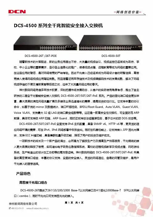
DCS-4500系列全千兆智能安全接入交换机DCS-4500-26T /26T-POE DCS-4500-50T 随着新技术的大军挺进,新的业务应用层出不穷,大流量的视频会议、视频监控已逐渐成为政府、学校、中小企业等的重要需求,各行各业信息化的推广,使得视频点播、远程教育等成为网络的重要应用。
在这些应用的背后,是对网络带宽的严峻考验。
因此千兆接入已经逐渐成为网络设计者的明智选择,高带宽接入使得网络视频应用驾轻就熟。
而且随着近两年存储技术及视频编解码技术的发展成熟,解决了网络视频存储的不便及清晰度差等后顾之忧,迎来了大流量网络应用的春天。
神州数码网络凭借多年技术积累,深刻把握市场发展动态,从客户的实际使用角度考虑,推出了自主研发的二层全千兆智能安全接入交换机DCS-4500-26T/50T/26T-PoE系列。
产品的固化端口组合更加丰富,最大限度的满足网络流量扩展及多媒体业务迅速增长的需要,提高投资的性价比。
它支持丰富的协议命令,如基于流的mirror及数据统计、端口环路检测、BPDU/Root Guard、Auto VLAN、Guest VLAN、Voice VLAN、支持最大32组LAG的端口聚合组数等等。
这还是一款高安全性交换机,可全面防范ARP 欺骗,具体可支持防ARP扫描、ARP Guard,同时还支持非法组播源检测,基于芯片的防DOS攻击等。
DCS-4500-26T/50T/26T-PoE全面支持IPv6主机配置,具备SNMP v6、HTTP v6等,更灵活的适应网络环境的需要,可在IPv4、IPv6网络部署中收放自如。
同时在机器性能上,它支持接入SFP百兆光模块,支持ECC纠错功能,具备集群批量升级功能,降低了用户的投资及维护成本。
一项新技术的成长及一个新产品的涌出,必然是为了解放生产力及提高生产效率服务,千兆铜缆的接入更大限度的释放了带宽,实现诸如电子政务应急指挥系统、高校的远程视频教学及视频点播、网吧游戏系统、生产制造业的设计加工协助等的高效率运转。
CloudEngine 12800 系列交换机V100R006C00NQA技术白皮书文档版本02发布日期2016-06-21版权所有 © 华为技术有限公司 2016。
保留一切权利。
非经本公司书面许可,任何单位和个人不得擅自摘抄、复制本文档内容的部分或全部,并不得以任何形式传播。
商标声明和其他华为商标均为华为技术有限公司的商标。
本文档提及的其他所有商标或注册商标,由各自的所有人拥有。
注意您购买的产品、服务或特性等应受华为公司商业合同和条款的约束,本文档中描述的全部或部分产品、服务或特性可能不在您的购买或使用范围之内。
除非合同另有约定,华为公司对本文档内容不做任何明示或默示的声明或保证。
由于产品版本升级或其他原因,本文档内容会不定期进行更新。
除非另有约定,本文档仅作为使用指导,本文档中的所有陈述、信息和建议不构成任何明示或暗示的担保。
华为技术有限公司地址:深圳市龙岗区坂田华为总部办公楼邮编:518129网址:目录1 NQA简介 (1)2 原理描述 (2)3 测试机制 (3)3.1 ICMP Jitter测试 (4)3.2 ICMP测试 (4)3.3 TCP测试 (5)3.4 Trace测试 (5)3.5 UDP Jitter测试 (6)3.6 LSP Ping测试 (7)3.7 LSP Trace测试 (7)4 NQA联动机制 (9)5 应用场景 (10)6 配置任务概览 (12)7 配置注意事项 (13)8 配置NQA测试例 (14)8.1 配置ICMP测试 (15)8.2 配置ICMP Jitter测试 (16)8.3 配置TCP测试 (18)8.4 配置Trace测试 (19)8.5 配置UDP Jitter测试 (20)8.6 配置LSP Ping测试 (22)8.7 配置LSP Trace测试 (23)8.8 查看配置结果 (25)9 配置NQA传输延迟阈值及阈值告警 (26)9.1 配置NQA双向传输延迟阈值 (27)9.2 配置NQA单向传输延迟阈值 (27)10 配置NQA测试的Trap开关 (28)10.1 使能NQA告警 (30)10.2 配置测试失败发送Trap (30)10.3 配置探测失败发送Trap (30)10.4 配置探测成功发送Trap (31)10.5 配置超过阈值发送Trap (31)10.6 检查配置结果 (32)11 调度NQA测试例 (33)11.1 启动NQA测试例 (34)11.2 (可选)终止NQA测试例 (35)11.3 查看测试结果 (35)12 维护NQA (37)12.1 清除统计信息 (38)13 配置举例 (39)13.1 配置ICMP测试示例 (40)13.2 配置ICMP Jitter测试示例 (42)13.3 配置TCP测试示例 (44)13.4 配置Trace测试示例 (47)13.5 配置UDP Jitter测试示例 (49)13.6 配置普通LSP隧道LSP Ping测试示例 (52)13.7 配置普通LSP隧道LSP Trace测试示例 (55)14 参考信息 (60)NQA技术白皮书 1 NQA简介1 NQA简介定义网络质量分析NQA(Network Quality Analysis)是一种实时的网络性能探测和统计技术,可以对响应时间、网络抖动、丢包率等网络信息进行统计。
首先,介绍下Cisco4系列和6系列交换机的种类。
Cisco Catalyst 4500 系列包括四种机箱:Cisco Catalyst 4510R-E(10个插槽)、Cisco Catalyst4507R-E(7个插槽)、Cisco Catalyst 4506-E(6个插槽)和 Cisco Catalyst 4503-E(3个插槽)。
Cisco Catalyst 6500系列也提供3插槽、6插槽、9插槽、13插槽的机箱,以及多种集成式模块。
下面对比Cisco Catalyst 4506和Cisco Catalyst6509两款交换机。
Cisco Catalyst 4500 系列和 Cisco Catalyst 4500 E 系列Cisco Catalyst 4500 系列包括“典型”管理引擎和线路卡,以及新开发的“E系列”管理引擎和线路卡。
典型管理引擎和线路卡的每个线路卡插槽提供6千兆交换容量,转发性能为102Mpps。
新开发的E 系列管理引擎和线路卡提供很多增强特性,包括每个线路卡插槽24千兆交换容量,以及250Mpps的总转发性能。
线路卡的向后兼容性:为增强功能而升级到新管理引擎之后,客户可以灵活地重用原有线路卡,也可以升级到更高性能的线路卡,而不需要改动整个系统,从而延缓了资本投入的时间。
顺利的技术迁移:客户可以根据自己的进度顺利迁移到线速 IPv6 或 10 千兆以太网。
对任意数量的IPv6 路径同时部署 IPv4 和 IPv6 不会影响整个系统的线速路由能力。
E系列管理引擎支持的 TwinGig转换器和 X2 模块以及万兆E 系列线路卡,使客户不需要执行管理引擎或线路卡升级,就能够使网络性能从千兆以太网增加到10 千兆以太网。
为未来特性留出余量:Cisco Catalyst 4500 系列架构配备了大量硬件资源,以支持未来特性,满足用户的未来网络需求。
只需对Cisco IOS Software作简单的升级,就可以在不执行整个系统升级的情况下发挥很多硬件特性的优势。
网吧网络解决方案第一部分相关介绍 (1)1.1 友讯公司简介 (1)第二部分网吧的常见问题 (3)2.1网吧常见问题 (3)2.2网吧行业建网问题原因 (5)第三部分网吧行业整体解决方案 (5)3.1D-Link 网吧典型网络解决方案 (5)3.1.1 D-Link 100台PC以下网吧网络解决方案 (9)3.1.2 D-Link 100-300台PC网吧网络解决方案 (10)3.1.3 D-Link 300-500台PC网吧网络解决方案 (12)3.1.4 D-Link 500台PC以上网吧网络解决方案 (15)3.1.5网络灾难援助解决方案 (16)第四部分网吧成功案例 (22)第一部分相关介绍1.1 友讯公司简介国际著名网络设备和解决方案提供商、全球无线网络领导品牌——D-Link(友讯网络)成立于1986年,并于1994年10月在中国台湾证券交易所挂牌上市,为中国台湾第一家成功上市的网络通讯设备厂商,在全球90多个国家设立办事处,以自创品牌“D-Link”秉承企业口号“Building Networks for People”行销电脑网络产品遍及全世界170多个国家。
作为网络通讯设备行业全球领导品牌,D-Link致力于局域网、宽带网、无线网、语音网、网络安全、网络存储、网络监控及相关网络设备的研发、生产和行销;在美国、中国大陆、中国台湾及印度设有研究发展中心,产品遍及全球,并拥有众多美国、日本、俄罗斯等国的世界级客户;2006年全球营业额为12.66亿美元,增长幅度高达15%,并获得全球消费类网络产品销量第一、全球SOHO宽带路由器销量第一、全球传统交换机销量第一及全球千兆传统交换机销量第一的桂冠,并再度入选美国《商业周刊》IT百强,核心竞争力“快速、创新、成本”得到充分体现。
1994年,D-Link进入中国大陆市场,自主主导D-Link在中国大陆的品牌经营。
在广东东莞设有制造工厂,在成都、北京设立了研发中心,设在东莞的工厂现在正在为D-Link全球市场供应着80%的产品。
数据中心交换机 buffer 需求分析白皮书目录1引言 (3)1.1DC 的网络性能要求 (3)1.2国内OTT 厂商对设备Buffer 的困惑 (4)1.3白皮书的目标 (4)2Buffer 需求的经典理论 (5)2.11BDP 理论 (5)2.2Nick Mckeown 理论 (6)2.3经典理论的适用性 (6)3基于尾丢弃的buffer 需求 (9)3.1丢包的影响 (9)3.1.2丢包对带宽利用率的影响 (9)3.1.3丢包对FCT 的影响 (12)3.2大buffer 的作用 (13)3.2.1吸收突发,减少丢包,保护吞吐 (13)3.2.2带宽分配均匀 (14)3.2.3优化FCT (15)3.3DC 内哪需要大buffer (15)3.4需要多大buffer (17)3.5带宽升级后,buffer 需求的变化 (19)3.6 小结 (19)4基于ECN 的buffer 需求 (21)4.1ECN 的作用 (21)4.2ECN 水线设置 (23)4.3基于ECN 的buffer 需要多大 (24)5基于大小流区分调度的buffer 需求 (27)5.1大小流差异化调度 (27)5.2大小流差异化调度如何实现大buffer 相当甚至更优的性能 (27)5.3基于大小流差异化调度的buffer 需要多大 (28)6 总结 (28)7 缩略语 (29)1 引言1.1DC 的网络性能要求近几年,大数据、云计算、社交网络、物联网等应用和服务高速发展,DC 已经成为承载这些服务的重要基础设施。
随着信息化水平的提高,移动互联网产业快速发展,尤其是视频、网络直播、游戏等行业的爆发式增长,用户对访问体验提出了更高的要求;云计算技术的广泛应用带动数据存储规模、计算能力以及网络流量的大幅增加;此外,物联网、智慧城市以及人工智能的发展也都对DC提出了更多的诉求。
为了满足不断增长的网络需求,DC 内的网络性能要求主要体现在:•低时延。
产品手册Cisco Catalyst 4500-X 系列万兆以太网固定配置交换机概述Cisco® Catalyst® 4500-X 系列交换机(图 1)属于固定配置交换机,它针对空间受限的园区环境,提供同类产品中最佳的可扩展性、简化的网络虚拟化和集成的网络服务。
此系列交换机具有前所未有的可扩展性,支持一对多(思科简易虚拟网络[EVN])和多对一(虚拟交换系统i[VSS])虚拟网络以简化网络虚拟化,并集成了很多网络服务以支持各种新兴应用,因此,完全能够满足业务增长的需要。
Cisco Catalyst 4500-X 系列融入了多项核心创新,其中包括:● 平台可扩展性:交换容量高达 800 Gbps,通过 VSS i技术可扩展到 1.6 Tbps。
模块化的上行链路和万兆位以太网与千兆位以太网端口自动检测功能,经得起未来考验。
● 高畅通性:此系列交换机具有包括 VSS i和 EVN 在内的全面高畅通性,能够为业务关键型企业应用提供所需的网络畅通性。
此外还有多项创新,例如具有多达五个冗余热插拔风扇;拥有交流到直流与直流到交流的供电故障切换功能以消除网络中的单点故障。
● 应用监控:通过 Flexible Netflow 和八个线速双向交换端口分析器 (SPAN)/远程交换端口分析器 (RSPAN),增强了应用监控能力。
此外 Cisco IOS® XE 软件提供托管第三方应用的功能。
●安全性:支持 Cisco TrustSec™技术和强大的控制平面策略 (CoPP) 功能,可防止拒绝服务攻击。
图 1. Cisco Catalyst 4500-X 系列交换机Cisco Catalyst 4500-X 系列交换机Cisco Catalyst 4500-X 系列提供可扩展的固定配置解决方案,适用于园区网络中空间有限的环境。
此解决方案通过两个版本的基础交换机以及可选的上行链路模块,可灵活地配置所需的端口密度。