Lattice XP2-8E-FT256引脚定义
- 格式:xls
- 大小:19.00 KB
- 文档页数:2
renesase2 引脚定义Renesas E2引脚定义Renesas E2引脚定义是指Renesas电子公司的E2型号芯片的引脚功能及其定义。
Renesas是一家全球领先的半导体制造商,其产品广泛应用于汽车、工业控制、消费电子等领域。
E2芯片是Renesas 的一款重要产品,它具有多种功能和特性,引脚定义是使用该芯片时必须了解的重要信息。
E2芯片的引脚定义如下:1. VDD:电源引脚,连接正极电源。
2. VSS:地引脚,连接负极电源。
3. XTAL1:晶体振荡器输入引脚,用于连接外部晶体振荡器。
4. XTAL2:晶体振荡器输出引脚,用于连接外部晶体振荡器。
5. RESET:复位引脚,用于对芯片进行复位操作。
6. P00-P07:通用输入/输出引脚,可用于连接外部设备或进行数据输入输出。
7. P10-P17:通用输入/输出引脚,具有与P00-P07相同的功能。
8. A0-A7:地址引脚,用于连接外部存储器或其他外部设备。
9. RD:读使能引脚,控制数据的读取操作。
10. WR:写使能引脚,控制数据的写入操作。
11. CE:片选引脚,用于选择芯片与外部设备之间的通信。
12. INT:中断引脚,用于传递中断信号。
通过以上引脚定义,可以看出E2芯片具有丰富的功能和灵活的扩展性。
其中,VDD和VSS引脚提供电源支持,XTAL1和XTAL2引脚用于外部振荡器的连接,RESET引脚用于复位操作,P00-P17引脚可用于输入输出和通信,A0-A7引脚用于地址传输,RD和WR引脚用于控制读写操作,CE引脚用于片选,INT引脚用于中断信号传递。
在实际应用中,根据具体需求,可以根据引脚定义连接外部设备,实现芯片与其他硬件的通信和控制。
例如,将P00-P07引脚连接到LED灯,可以实现LED的控制;将A0-A7引脚连接到存储器,可以实现数据的读写操作;通过RD和WR引脚,可以控制读写操作的时序;通过INT引脚,可以实现中断功能等。
IC卡基础知识(引脚,特点及读写时序图)--------------------------------------------------------------------------------IC卡基础知识(引脚,特点及读写时序图)自从80年代中期出现IC电话卡后,基本已取代了原来流行的电话磁卡,磁卡存在存在严重的安全问题,已逐步淘汰。
即使IC电话卡,也不能算很安全,卡内所有数据只要有简单的读写装置并按时序操作都能读取,事实上电话卡和信用卡一样内部没有什么秘密信息,仅仅是带串行输出的128位EPROM而已(对二类卡是256位PROM),不要以为弄懂了它是怎么工作你就有办法重新对卡内数据重新填充,其开始的64位是带写保护的,在出厂时其熔丝位已被编程,你已无法对其更改,其后的40位计数单元受内部逻辑控制在写时只能减少不能增加直至到0为止,因此你想用一般的IC电话卡打免费电话是不可能的,除非你能用微控制器(单片机)仿真它(如果你能读懂本文介绍的所有内容)。
IC电话卡是一种一次性使用的计数卡,以一次性的计数方式,从写满的计数器中减“1”,直至存储单元减为空为止。
卡片每次消费计数的“单位价值”根据各种应用系统的实际需要而定。
例如:对于中国IC 电话卡,如30元卡对应内部计数值为300,每单位值对应0.1元,IC 卡电话机每分钟产生一次扣费信号,扣费值由当地IC电话管理系统设定,一般是价值0.5元或1元,卡片被计数5次和10次。
对于其它国家属于第一类IC电话卡而言也是如此,只是内部初始计数值不同,每次扣除额度不一样罢了。
其他对于公用加油卡,IC卡计费加油机每一公升(或一加仑)产生一次扣费操作,卡片被操作一次扣2.5元等等,均属于等同原理。
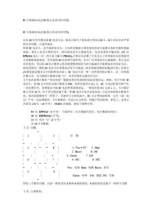
事实上,这类卡内部为128位(16字节)NMOS存储器,按如下规律分布:64 位EPPOM(8字节)写保护区(芯片数据代码区、发行数据代码区)40 位EEPROM(5字节)24 位为全“1”(3字节)共16字节数据。
TF卡引脚定义,SD卡引脚定义TF卡引脚定义micro sd引脚定义类别:网文精粹阅读:1363TF卡全名(TransFLash),这是Motorola与SanDisk共同推出的最新一代的记忆卡规格,它采用了最新的封装技术,并配合SanDisk最新NAND MLC技术及控制器技术。
大小(11mm x 15mm x1mm),约等于半张SIM卡,Trans-Flash Card为SD Card产品成员的一员,附有SD转接器,可兼容任何SD读卡器,TF卡可经SD卡转换器后,当SD卡使用。
T-Flash卡是市面上最小的闪存卡,适用于多项多媒体应用.TF卡产品采用SD架构设计而成,SD协会于2004年年底正式将其更名为Micro SD,已成为SD产品中的一员。
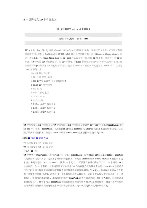
SD卡引脚定义如下:针脚名称类型描述1 CD DAT3 I/O/PP 卡监测数据位32 CMD PP 命令/回复3 Vss S 地4 Vcc S 供电电压5 CLK I 时钟6 Css2 S 地7 DAT0 I/O/PP 数据位08 DAT1 I/O/PP 数据位19 DAT2 I/O/PP 数据位2TAG:IT培训IT认证考试TF卡引脚定义,SD卡引脚定义TF卡引脚定义/SD卡引脚定义什么叫TF卡:TF卡全名(TransFLash),又称T-Flash卡,全名:TransFLash,又名:Micro SD,这是Motorola与SanDisk 共同推出的记忆卡规格,它采用了最新的封装技术,并配合SanDisk最新NAND MLC技术及控制器技术.是一种超小型卡(11*15*1MM),约为SD卡的1/4,可以算目前最小的储存卡了。
TF卡可经SD卡转换器后,当SD卡使用。
利用适配器可以在使用SD作为存储介质的设备上使用。
TransFlash主要是为照相手机拍摄大幅图像以及能够下载较大的视频片段而开发研制的。
TransFlash卡可以用来储存个人数据,例如数字照片、MP3、游戏及用于手机的应用和个人数据等,还内设置版权保护管理系统,让下载的音乐、影像及游戏受保护;未来推出的新型TransFlash还备有加密功能,保护个人数据、财政纪录及健康医疗文件。
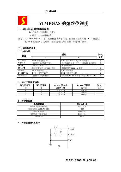
February 2008Preliminary Data Sheet DS1009© 2008 Lattice Semiconductor Corp. All Lattice trademarks, registered trademarks, patents, and disclaimers are as listed at /legal. All other brand Features■ flexiFLASH™ Architecture•Instant-on•Infinitely reconfigurable •Single chip•FlashBAK™ technology •Serial T AG memory •Design security■ Live Update Technology•T ransFR™ technology•Secure updates with 128 bit AES encryption •Dual-boot with external SPI■ sysDSP™ Block•Three to eight blocks for high performance Multiply and Accumulate •12 to 32 18x18 multipliers•Each block supports one 36x36 multiplier or four 18x18 or eight 9x9 multipliers ■ Embedded and Distributed Memory •Up to 885 Kbits sysMEM™ EBR •Up to 83 Kbits Distributed RAM■ sysCLOCK™ PLLs•Up to four analog PLLs per device•Clock multiply, divide and phase shifting■ Flexible I/O Buffer•sysIO™ buffer supports:–LVCMOS 33/25/18/15/12; LVTTL –SSTL 33/25/18 class I, II–HSTL15 class I; HSTL18 class I, II –PCI–LVDS, Bus-LVDS, MLVDS, LVPECL, RSDS ■ Pre-engineered Source SynchronousInterfaces•DDR / DDR2 interfaces up to 200 MHz•7:1 LVDS interfaces support display applications •XGMII■ Density And Package Options•5k to 40k LUT4s, 86 to 540 I/Os •csBGA, TQFP , PQFP , ftBGA and fpBGA packages •Density migration supported■ Flexible Device Configuration•SPI (master and slave) Boot Flash Interface •Dual Boot Image supported•Soft Error Detect (SED) macro embedded■ System Level Support•IEEE 1149.1 and IEEE 1532 Compliant•On-chip oscillator for initialization & general use •Devices operate with 1.2V power supplyTable 1-1. LatticeXP2 Family Selection GuideDevice XP2-5XP2-8XP2-17XP2-30XP2-40 LUTs (K)58172940Distributed RAM (KBits)1018355683EBR SRAM (KBits)166221276387885EBR SRAM Blocks 912152148sysDSP Blocks 3457818 x 18 Multipliers 1216202832V CC Voltage 1.2 1.2 1.2 1.2 1.2GPLL22444Max Available I/O172201358472540Packages and I/O Combinations132-Ball csBGA (8 x 8 mm) 8686 144-Pin TQFP (20 x 20 mm) 100100 208-Pin PQFP (28 x 28 mm) 146146146 256-Ball ftBGA (17 x17 mm) 172201201201 484-Ball fpBGA (23 x 23 mm) 358363363672-Ball fpBGA (27 x 27 mm)472540LatticeXP2 Family Data SheetIntroductionIntroduction Lattice Semiconductor LatticeXP2 Family Data Sheet IntroductionLatticeXP2 devices combine a Look-up T able (LUT) based FPGA fabric with non-volatile Flash cells in an architec-ture referred to as flexiFLASH.The flexiFLASH approach provides benefits including instant-on, infinite reconfigurability, on chip storage with FlashBAK embedded block memory and Serial T AG memory and design security. The parts also support Live Update technology with T ransFR, 128-bit AES Encryption and Dual-boot technologies.The LatticeXP2 FPGA fabric was optimized for the new technology from the outset with high performance and low cost in mind. LatticeXP2 devices include LUT-based logic, distributed and embedded memory, Phase Locked Loops (PLLs), pre-engineered source synchronous I/O support and enhanced sysDSP blocks.The ispLEVER® design tool from Lattice allows large and complex designs to be efficiently implemented using the LatticeXP2 family of FPGA devices. Synthesis library support for LatticeXP2 is available for popular logic synthesis tools. The ispLEVER tool uses the synthesis tool output along with the constraints from its floor planning tools to place and route the design in the LatticeXP2 device. The ispLEVER tool extracts the timing from the routing and back-annotates it into the design for timing verification.Lattice provides many pre-designed Intellectual Property (IP) ispLeverCORE™ modules for the LatticeXP2 family. By using these IPs as standardized blocks, designers are free to concentrate on the unique aspects of their design, increasing their productivity.February 2008Preliminary Data Sheet DS1009© 2008 Lattice Semiconductor Corp. All Lattice trademarks, registered trademarks, patents, and disclaimers are as listed at /legal. All other brand Architecture OverviewEach LatticeXP2 device contains an array of logic blocks surrounded by Programmable I/O Cells (PIC). Inter-spersed between the rows of logic blocks are rows of sysMEM™ Embedded Block RAM (EBR) and a row of sys-DSP™ Digital Signal Processing blocks as shown in Figure 2-1.On the left and right sides of the Programmable Functional Unit (PFU) array, there are Non-volatile Memory Blocks.In configuration mode the nonvolatile memory is programmed via the IEEE 1149.1 T AP port or the sysCONFIG™peripheral port. On power up, the configuration data is transferred from the Non-volatile Memory Blocks to the con-figuration SRAM. With this technology, expensive external configuration memory is not required, and designs are secured from unauthorized read-back. This transfer of data from non-volatile memory to configuration SRAM via wide busses happens in microseconds, providing an “instant-on” capability that allows easy interfacing in many applications. LatticeXP2 devices can also transfer data from the sysMEM EBR blocks to the Non-volatile Memory Blocks at user request.There are two kinds of logic blocks, the PFU and the PFU without RAM (PFF). The PFU contains the building blocks for logic, arithmetic, RAM and ROM functions. The PFF block contains building blocks for logic, arithmetic and ROM functions. Both PFU and PFF blocks are optimized for flexibility allowing complex designs to be imple-mented quickly and efficiently. Logic Blocks are arranged in a two-dimensional array. Only one type of block is used per row.LatticeXP2 devices contain one or more rows of sysMEM EBR blocks. sysMEM EBRs are large dedicated 18Kbit memory blocks. Each sysMEM block can be configured in a variety of depths and widths of RAM or ROM. In addi-tion, LatticeXP2 devices contain up to two rows of DSP Blocks. Each DSP block has multipliers and adder/accumu-lators, which are the building blocks for complex signal processing capabilities.Each PIC block encompasses two PIOs (PIO pairs) with their respective sysIO buffers. The sysIO buffers of the LatticeXP2 devices are arranged into eight banks, allowing the implementation of a wide variety of I/O standards. In addition, a separate I/O bank is provided for programming interfaces. PIO pairs on the left and right edges of the device can be configured as LVDS transmit/receive pairs. The PIC logic also includes pre-engineered support to aid in the implementation of high speed source synchronous standards such as 7:1 LVDS interfaces, found in many display applications, and memory interfaces including DDR and DDR2.Other blocks provided include PLLs and configuration functions. The LatticeXP2 architecture provides up to four General Purpose PLLs (GPLL) per device. The GPLL blocks are located in the corners of the device.The configuration block that supports features such as configuration bit-stream de-encryption, transparent updates and dual boot support is located between banks two and three. Every device in the LatticeXP2 family supports a sysCONFIG port, muxed with bank seven I/Os, which supports serial device configuration. A JT AG port is provided between banks two and three.This family also provides an on-chip oscillator and Soft Error Detect (SED) capability. LatticeXP2 devices use 1.2V as their core voltage.LatticeXP2 Family Data SheetArchitectureArchitecture Lattice Semiconductor LatticeXP2 Family Data Sheet Figure 2-1. Simplified Block Diagram, LatticeXP2-17 Device (Top Level)PFU BlocksThe core of the LatticeXP2 device is made up of logic blocks in two forms, PFUs and PFFs. PFUs can be pro-grammed to perform logic, arithmetic, distributed RAM and distributed ROM functions. PFF blocks can be pro-grammed to perform logic, arithmetic and ROM functions. Except where necessary, the remainder of this data sheet will use the term PFU to refer to both PFU and PFF blocks.Each PFU block consists of four interconnected slices, numbered Slice 0 through Slice 3, as shown in Figure 2-2. All the interconnections to and from PFU blocks are from routing. There are 50 inputs and 23 outputs associated with each PFU block.ArchitectureLattice SemiconductorLatticeXP2 Family Data SheetFigure 2-2. PFU DiagramSliceSlice 0 through Slice 2 contain two 4-input combinatorial Look-Up T ables (LUT4), which feed two registers. Slice 3contains two LUT4s and no registers. For PFUs, Slice 0 and Slice 2 can also be configured as distributed memory,a capability not available in PFF blocks. T able 2-1 shows the capability of the slices in both PFF and PFU blocks along with the operation modes they enable. In addition, each PFU contains logic that allows the LUTs to be com-bined to perform functions such as LUT5, LUT6, LUT7 and LUT8. There is control logic to perform set/reset func-tions (programmable as synchronous/asynchronous), clock select, chip-select and wider RAM/ROM functions.Figure 2-3 shows an overview of the internal logic of the slice. The registers in the slice can be configured as posi-tive/negative edge triggered or level sensitive clocks. Table 2-1. Resources and Modes Available per SliceSlice 0 through Slice 2 have 14 input signals: 13 signals from routing and one from the carry-chain (from the adja-cent slice or PFU). There are seven outputs: six to routing and one to carry-chain (to the adjacent PFU). Slice 3 has 13 input signals from routing and four signals to routing. T able 2-2 lists the signals associated with Slice 0 to Slice 2.Slice PFU BLockPFF BlockResources Modes Resources ModesSlice 0 2 LUT4s and 2 Registers Logic, Ripple, RAM, ROM 2 LUT4s and 2 Registers Logic, Ripple, ROM Slice 1 2 LUT4s and 2 RegistersLogic, Ripple, ROM2 LUT4s and 2 RegistersLogic, Ripple, ROM Slice 2 2 LUT4s and 2 Registers Logic, Ripple, RAM, ROM 2 LUT4s and 2 RegistersLogic, Ripple, ROMSlice 32 LUT4sLogic, ROM2 LUT4sLogic, ROMArchitecture Lattice Semiconductor LatticeXP2 Family Data Sheet Figure 2-3. Slice DiagramTable 2-2. Slice Signal DescriptionsFunction Type SignalNames Description Input Data signal A0, B0, C0, D0 Inputs to LUT4Input Data signal A1, B1, C1, D1 Inputs to LUT4Input Multi-purpose M0 MultipurposeInputInput Multi-purpose M1 MultipurposeInputInput Control signal CE Clock EnableInput Control signal LSR Local Set/ResetInput Control signal CLK System ClockInput Inter-PFU signal FCI Fast Carry-In1Input Inter-slice signal FXA Intermediate signal to generate LUT6 and LUT7Input Inter-slice signal FXB Intermediate signal to generate LUT6 and LUT7Output Data signals F0, F1 LUT4 output register bypass signalsOutput Data signals Q0, Q1 Register outputsOutput Data signals OFX0 Output of a LUT5 MUXOutput Data signals OFX1 Output of a LUT6, LUT7, LUT82 MUX depending on the sliceOutput Inter-PFU signal FCO Slice 2 of each PFU is the fast carry chain output11.See Figure 2-3 for connection details.2.Requires two PFUs.Architecture Lattice Semiconductor LatticeXP2 Family Data Sheet Modes of OperationEach slice has up to four potential modes of operation: Logic, Ripple, RAM and ROM.Logic ModeIn this mode, the LUTs in each slice are configured as LUT4s. A LUT4 has 16 possible input combinations. Four-input logic functions are generated by programming the LUT4. Since there are two LUT4s per slice, a LUT5 can be constructed within one slice. Larger LUTs such as LUT6, LUT7 and LUT8, can be constructed by concatenating two or more slices. Note that a LUT8 requires more than four slices.Ripple ModeRipple mode allows efficient implementation of small arithmetic functions. In ripple mode, the following functions can be implemented by each slice:•Addition 2-bit•Subtraction 2-bit•Add/Subtract 2-bit using dynamic control•Up counter 2-bit•Down counter 2-bit•Up/Down counter with async clear•Up/Down counter with preload (sync)•Ripple mode multiplier building block•Multiplier support•Comparator functions of A and B inputs–A greater-than-or-equal-to B–A not-equal-to B–A less-than-or-equal-to BT wo carry signals, FCI and FCO, are generated per slice in this mode, allowing fast arithmetic functions to be con-structed by concatenating slices.RAM ModeIn this mode, a 16x4-bit distributed Single Port RAM (SPR) can be constructed using each LUT block in Slice 0 and Slice 2 as a 16x1-bit memory. Slice 1 is used to provide memory address and control signals. A 16x2-bit Pseudo Dual Port RAM (PDPR) memory is created by using one slice as the read-write port and the other companion slice as the read-only port.The Lattice design tools support the creation of a variety of different size memories. Where appropriate, the soft-ware will construct these using distributed memory primitives that represent the capabilities of the PFU. T able 2-3 shows the number of slices required to implement different distributed RAM primitives. For more information on using RAM in LatticeXP2 devices, please see TN1137, LatticeXP2 Memory Usage Guide.Table 2-3. Number of Slices Required For Implementing Distributed RAMSPR 16X4PDPR 16X4 Number of slices33Note: SPR = Single Port RAM, PDPR = Pseudo Dual Port RAMROM ModeROM mode uses the LUT logic; hence, Slices 0 through 3 can be used in the ROM mode. Preloading is accom-plished through the programming interface during PFU configuration.Architecture Lattice Semiconductor LatticeXP2 Family Data Sheet RoutingThere are many resources provided in the LatticeXP2 devices to route signals individually or as busses with related control signals. The routing resources consist of switching circuitry, buffers and metal interconnect (routing) seg-ments.The inter-PFU connections are made with x1 (spans two PFU), x2 (spans three PFU) or x6 (spans seven PFU) connections. The x1 and x2 connections provide fast and efficient connections in horizontal and vertical directions. The x2 and x6 resources are buffered to allow both short and long connections routing between PFUs.The LatticeXP2 family has an enhanced routing architecture to produce a compact design. The ispLEVER design tool takes the output of the synthesis tool and places and routes the design. Generally, the place and route tool is completely automatic, although an interactive routing editor is available to optimize the design.sysCLOCK Phase Locked Loops (PLL)The sysCLOCK PLLs provide the ability to synthesize clock frequencies. The LatticeXP2 family supports between two and four full featured General Purpose PLLs (GPLL). The architecture of the GPLL is shown in Figure 2-4.CLKI, the PLL reference frequency, is provided either from the pin or from routing; it feeds into the Input Clock Divider block. CLKFB, the feedback signal, is generated from CLKOP (the primary clock output) or from a user clock pin/logic. CLKFB feeds into the Feedback Divider and is used to multiply the reference frequency.Both the input path and feedback signals enter the Voltage Controlled Oscillator (VCO) block. The phase and fre-quency of the VCO are determined from the input path and feedback signals. A LOCK signal is generated by the VCO to indicate that the VCO is locked with the input clock signal.The output of the VCO feeds into the CLKOP Divider, a post-scalar divider. The duty cycle of the CLKOP Divider output can be fine tuned using the Duty T rim block, which creates the CLKOP signal. By allowing the VCO to oper-ate at higher frequencies than CLKOP, the frequency range of the GPLL is expanded. The output of the CLKOP D ivider is passed through the CLKOK D ivider, a secondary clock divider, to generate lower frequencies for the CLKOK output. For applications that require even lower frequencies, the CLKOP signal is passed through a divide-by-three divider to produce the CLKOK2 output. The CLKOK2 output is provided for applications that use source synchronous logic. The Phase/Duty Cycle/Duty T rim block is used to adjust the phase and duty cycle of the CLKOP Divider output to generate the CLKOS signal. The phase/duty cycle setting can be pre-programmed or dynamically adjusted.The clock outputs from the GPLL; CLKOP, CLKOK, CLKOK2 and CLKOS, are fed to the clock distribution network.For further information on the GPLL please see TN1126, LatticeXP2 sysCLOCK PLL Design and Usage Guide.ArchitectureLattice SemiconductorLatticeXP2 Family Data SheetFigure 2-4. General Purpose PLL (GPLL) DiagramT able 2-4 provides a description of the signals in the GPLL blocks. Table 2-4. GPLL Block Signal DescriptionsClock DividersLatticeXP2 devices have two clock dividers, one on the left side and one on the right side of the device. These are intended to generate a slower-speed system clock from a high-speed edge clock. The block operates in a ÷2, ÷4 or ÷8 mode and maintains a known phase relationship between the divided down clock and the high-speed clock based on the release of its reset signal. The clock dividers can be fed from the CLKOP output from the GPLLs or from the Edge Clocks (ECLK). The clock divider outputs serve as primary clock sources and feed into the clock dis-tribution network. The Reset (RST) control signal resets the input and forces all outputs to low. The RELEASE sig-nal releases outputs to the input clock. For further information on clock dividers, please see TN1126, sysCLOCK PLL Design and Usage Guide. Figure 2-5 shows the clock divider connections.Signal I/O DescriptionCLKIIClock input from external pin or routingCLKFB IPLL feedback input from CLKOP (PLL internal), from clock net (CLKOP) or from a user clock(PIN or logic) RST I “1” to reset PLL counters, VCO, charge pumps and M-dividers RSTK I “1” to reset K-divider DPHASE [3:0]I DP A Phase Adjust input DDDUTY [3:0]I DP A Duty Cycle Select input WRDEL I DP A Fine Delay Adjust inputCLKOS O PLL output clock to clock tree (phase shifted/duty cycle changed) CLKOP O PLL output clock to clock tree (no phase shift)CLKOK O PLL output to clock tree through secondary clock divider CLKOK2O PLL output to clock tree (CLKOP divided by 3)LOCKO“1” indicates PLL LOCK to CLKIArchitecture Lattice Semiconductor LatticeXP2 Family Data Sheet Figure 2-5. Clock Divider ConnectionsClock Distribution NetworkLatticeXP2 devices have eight quadrant-based primary clocks and between six and eight flexible region-based sec-ondary clocks/control signals. T wo high performance edge clocks are available on each edge of the device to sup-port high speed interfaces. The clock inputs are selected from external I/Os, the sysCLOCK PLLs, or routing. Clock inputs are fed throughout the chip via the primary, secondary and edge clock networks.Primary Clock SourcesLatticeXP2 devices derive primary clocks from four sources: PLL outputs, CLKDIV outputs, dedicated clock inputs and routing. LatticeXP2 devices have two to four sysCLOCK PLLs, located in the four corners of the device. There are eight dedicated clock inputs, two on each side of the device. Figure 2-6 shows the primary clock sources.Figure 2-6. Primary Clock Sources for XP2-17Secondary Clock/Control SourcesLatticeXP2 devices derive secondary clocks (SC0 through SC7) from eight dedicated clock input pads and the rest from routing. Figure 2-7 shows the secondary clock sources.Figure 2-7. Secondary Clock SourcesEdge Clock SourcesEdge clock resources can be driven from a variety of sources at the same edge. Edge clock resources can be driven from adjacent edge clock PIOs, primary clock PIOs, PLLs and clock dividers as shown in Figure 2-8. Figure 2-8. Edge Clock SourcesArchitecture Lattice Semiconductor LatticeXP2 Family Data Sheet Primary Clock RoutingThe clock routing structure in LatticeXP2 devices consists of a network of eight primary clock lines (CLK0 through CLK7) per quadrant. The primary clocks of each quadrant are generated from muxes located in the center of the device. All the clock sources are connected to these muxes. Figure 2-9 shows the clock routing for one quadrant. Each quadrant mux is identical. If desired, any clock can be routed globally.Figure 2-9. Per Quadrant Primary Clock SelectionDynamic Clock Select (DCS)The DCS is a smart multiplexer function available in the primary clock routing. It switches between two independent input clock sources without any glitches or runt pulses. This is achieved irrespective of when the select signal is toggled. There are two DCS blocks per quadrant; in total, eight DCS blocks per device. The inputs to the DCS block come from the center muxes. The output of the DCS is connected to primary clocks CLK6 and CLK7 (see Figure 2-9).Figure 2-10 shows the timing waveforms of the default DCS operating mode. The DCS block can be programmed to other modes. For more information on the DCS, please see TN1126, LatticeXP2 sysCLOCK PLL Design and Usage Guide.Figure 2-10. DCS WaveformsSecondary Clock/Control RoutingSecondary clocks in the LatticeXP2 devices are region-based resources. EBR rows, DSP rows and a special verti-cal routing channel bound the secondary clock regions. This special vertical routing channel aligns with either the left edge of the center DSP block in the DSP row or the center of the DSP row. Figure 2-11 shows this special ver-tical routing channel and the eight secondary clock regions for the LatticeXP2-40. LatticeXP2-30 and smallerArchitecture Lattice Semiconductor LatticeXP2 Family Data Sheet devices have six secondary clock regions. All devices in the LatticeXP2 family have eight secondary clock resources per region (SC0 to SC7).The secondary clock muxes are located in the center of the device. Figure 2-12 shows the mux structure of the secondary clock routing. Secondary clocks SC0 to SC3 are used for high fan-out control and SC4 to SC7 are used for clock signals.Figure 2-11. Secondary Clock Regions XP2-40Figure 2-12. Per Region Secondary Clock SelectionArchitecture Lattice Semiconductor LatticeXP2 Family Data Sheet Slice Clock SelectionFigure 2-13 shows the clock selections and Figure 2-14 shows the control selections for Slice0 through Slice2. All the primary clocks and the four secondary clocks are routed to this clock selection mux. Other signals, via routing, can be used as clock inputs to the slices. Slice controls are generated from the secondary clocks or other signals connected via routing.If none of the signals are selected for both clock and control, then the default value of the mux output is 1. Slice 3 does not have any registers; therefore it does not have the clock or control muxes.Figure 2-13. Slice0 through Slice2 Clock SelectionFigure 2-14. Slice0 through Slice2 Control SelectionEdge Clock RoutingLatticeXP2 devices have eight high-speed edge clocks that are intended for use with the PIOs in the implementa-tion of high-speed interfaces. Each device has two edge clocks per edge. Figure 2-15 shows the selection muxes for these clocks.Architecture Lattice Semiconductor LatticeXP2 Family Data Sheet Figure 2-15. Edge Clock Mux ConnectionssysMEM MemoryLatticeXP2 devices contains a number of sysMEM Embedded Block RAM (EBR). The EBR consists of 18 Kbit RAM with dedicated input and output registers.sysMEM Memory BlockThe sysMEM block can implement single port, dual port or pseudo dual port memories. Each block can be used in a variety of depths and widths as shown in T able 2-5. FIFOs can be implemented in sysMEM EBR blocks by using support logic with PFUs. The EBR block supports an optional parity bit for each data byte to facilitate parity check-ing. EBR blocks provide byte-enable support for configurations with18-bit and 36-bit data widths.ArchitectureLattice SemiconductorLatticeXP2 Family Data SheetTable 2-5. sysMEM Block ConfigurationsBus Size MatchingAll of the multi-port memory modes support different widths on each of the ports. The RAM bits are mapped LSB word 0 to MSB word 0, LSB word 1 to MSB word 1, and so on. Although the word size and number of words for each port varies, this mapping scheme applies to each port.FlashBAK EBR Content StorageAll the EBR memory in the LatticeXP2 is shadowed by Flash memory. Optionally, initialization values for the mem-ory blocks can be defined using the Lattice ispLEVER tools. The initialization values are loaded into the Flash memory during device programming and into the SRAM at power up or whenever the device is reconfigured. This feature is ideal for the storage of a variety of information such as look-up tables and microprocessor code. It is also possible to write the current contents of the EBR memory back to Flash memory. This capability is useful for the storage of data such as error codes and calibration information. For additional information on the FlashBAK capa-bility see TN1141, LatticeXP2 sysCONFIG Usage Guide. Figure 2-16. FlashBAK TechnologyMemory CascadingLarger and deeper blocks of RAMs can be created using EBR sysMEM Blocks. T ypically, the Lattice design tools cascade memory transparently, based on specific design inputs.Single, Dual and Pseudo-Dual Port ModesIn all the sysMEM RAM modes the input data and address for the ports are registered at the input of the memory array. The output data of the memory is optionally registered at the output.Memory ModeConfigurationsSingle Port16,384 x 18,192 x 24,096 x 42,048 x 91,024 x 18512 x 36T rue Dual Port16,384 x 18,192 x 24,096 x 42,048 x 91,024 x 18Pseudo Dual Port16,384 x 18,192 x 24,096 x 42,048 x 91,024 x 18512 x 36Architecture Lattice Semiconductor LatticeXP2 Family Data Sheet EBR memory supports three forms of write behavior for single port or dual port operation:1.Normal – Data on the output appears only during a read cycle. During a write cycle, the data (at the currentaddress) does not appear on the output. This mode is supported for all data widths.2.Write Through – A copy of the input data appears at the output of the same port during a write cycle. This modeis supported for all data widths.3.Read-Before-Write – When new data is being written, the old content of the address appears at the output.This mode is supported for x9, x18 and x36 data widths.Memory Core ResetThe memory array in the EBR utilizes latches at the A and B output ports. These latches can be reset asynchro-nously or synchronously. RST A and RSTB are local signals, which reset the output latches associated with Port A and Port B respectively. GSRN, the global reset signal, resets both ports. The output data latches and associated resets for both ports are as shown in Figure 2-17.Figure 2-17. Memory Core ResetFor further information on the sysMEM EBR block, please see TN1137, LatticeXP2 Memory Usage Guide.EBR Asynchronous ResetEBR asynchronous reset or GSR (if used) can only be applied if all clock enables are low for a clock cycle before the reset is applied and released a clock cycle after the low-to-high transition of the reset signal, as shown in Figure 2-18. The GSR input to the EBR is always asynchronous.Figure 2-18. EBR Asynchronous Reset (Including GSR) Timing DiagramArchitecture Lattice Semiconductor LatticeXP2 Family Data Sheet If all clock enables remain enabled, the EBR asynchronous reset or GSR may only be applied and released after the EBR read and write clock inputs are in a steady state condition for a minimum of 1/f MAX (EBR clock). The reset release must adhere to the EBR synchronous reset setup time before the next active read or write clock edge.If an EBR is pre-loaded during configuration, the GSR input must be disabled or the release of the GSR during device Wake Up must occur before the release of the device I/Os becoming active.These instructions apply to all EBR RAM and ROM implementations.Note that there are no reset restrictions if the EBR synchronous reset is used and the EBR GSR input is disabled. sysDSP™ BlockThe LatticeXP2 family provides a sysDSP block making it ideally suited for low cost, high performance Digital Sig-nal Processing (DSP) applications. T ypical functions used in these applications include Bit Correlators, Fast Fourier T ransform (FFT) functions, Finite Impulse Response (FIR) Filter, Reed-Solomon Encoder/Decoder, T urbo Encoder/ D ecoder and Convolutional Encoder/D ecoder. These complex signal processing functions use similar building blocks such as multiply-adders and multiply-accumulators.sysDSP Block Approach Compare to General DSPConventional general-purpose DSP chips typically contain one to four (Multiply and Accumulate) MAC units with fixed data-width multipliers; this leads to limited parallelism and limited throughput. Their throughput is increased by higher clock speeds. The LatticeXP2 family, on the other hand, has many DSP blocks that support different data-widths. This allows the designer to use highly parallel implementations of DSP functions. The designer can opti-mize the DSP performance vs. area by choosing appropriate levels of parallelism. Figure 2-19 compares the fully serial and the mixed parallel and serial implementations.Figure 2-19. Comparison of General DSP and LatticeXP2 ApproachessysDSP Block CapabilitiesThe sysD SP block in the LatticeXP2 family supports four functional elements in three 9, 18 and 36 data path widths. The user selects a function element for a DSP block and then selects the width and type (signed/unsigned) of its operands. The operands in the LatticeXP2 family sysDSP Blocks can be either signed or unsigned but not。

1.下载口。
JTAG下载接口,对应下载的文件是SOF文件,速度快,JTAG 将程序直接下载到FPGA中,但是掉电程序丢失,平时学习推荐使用JTAG方式,最后固化程序的时候再通过AS方式将程序下载到配置芯片中即可;AS下载接口,对应下载的是POF文件,速度相对较慢,需要重新上电并且拔掉下载线,才能工作,操作相对麻烦,不推荐学习的时候使用。
2.FPGA引脚作用:(1)VCCINT:这些都是内部逻辑阵列电源电压引脚。
VCCINT还可以给输入缓冲区供电,用于LVPECL,LVDS(常规I / O和CLK引脚),差分HSTL,差分SSTL I/ O标准。
Connect all VCCINT pins to 1.2 V. Decoupling depends on the design decoupling requirementsof the specific board.所有VCCINT引脚连接至1.2 V,去耦依赖于设计脱钩的要求的具体电路板。
(2)VCCIO[1…8]: 这些I / O电源电压引脚银行1至8。
每个组可以支持不同的电压水平。
VCCIO供电到输出缓冲区,所有的I / O标准。
VCCIO供电输入缓冲区用于LVTTL,LVCMOS,1.5-V,1.8 V,2.5 V,3.3 V PCI,和3.3-V PCI-X,差分SSTL。
差分HSTL。
和LVDS lrecular我/ OL I / O标准。
验证VCCIO电压等级连接是与QuartusII软件的引脚连接一致。
去耦取决于设计去耦的具体要求的具体电路板。
(3)VREFB[1..8]N[0..3]: 为每个I / O组的输入参考电压。
这些引脚被用来作电压参考引脚。
如果没有被用,就作为普通的I/O引脚。
(4)VCCA PLL[1..4]: 模拟电源锁相环[1 ..4].将这些引脚连接到1.2 V,即使不使用PLL。
更好的,使用一个孤立的线性电源钳工性能。

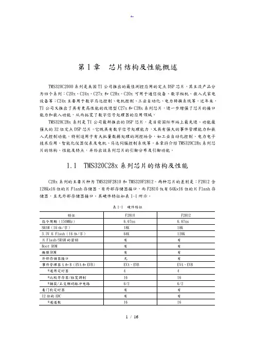
第1章芯片结构及性能概述TMS320C2000系列是美国TI公司推出的最佳测控应用的定点DSP芯片,其主流产品分为四个系列:C20x、C24x、C27x和C28x。
C20x可用于通信设备、数字相机、嵌入式家电设备等;C24x主要用于数字马达控制、电机控制、工业自动化、电力转换系统等。
近年来,TI公司又推出了具有更高性能的改进型C27x和C28x系列芯片,进一步增强了芯片的接口能力和嵌入功能,从而拓宽了数字信号处理器的应用领域。
TMS320C28x系列是TI公司最新推出的DSP芯片,是目前国际市场上最先进、功能最强大的32位定点DSP芯片。
它既具有数字信号处理能力,又具有强大的事件管理能力和嵌入式控制功能,特别适用于有大批量数据处理的测控场合,如工业自动化控制、电力电子技术应用、智能化仪器仪表及电机、马达伺服控制系统等。
本章将介绍TMS320C28x系列芯片的结构、性能及特点,并给出该系列芯片的引脚分布及引脚功能。
1.1 TMS320C28x系列芯片的结构及性能C28x系列的主要片种为TMS320F2810和TMS320F2812。
两种芯片的差别是:F2812含128K×16位的片Flash存储器,有外部存储器接口,而F2810仅有64K×16位的片Flash存储器,且无外部存储器接口。
其硬件特征如表1-1所示。
表1-1 硬件特征1 / 16注:‡“S”是温度选择(-40℃ ~ +125℃)的特征化数据,仅对TMS是适用的。
‡‡产品预览(PP):在开发阶段的形成和设计中与产品有关的信息,特征数据和其他规格是设计的目标。
TI保留了正确的东西,更换或者终止了一些没有注意到的产品。
高级信息(AI):在开发阶段的取样和试制中与新产品有关的信息,特征数据和其他规格用以改变那些没有注意到的东西。
产品数据(PD):是当前公布的数据信息,产品遵守TI的每项标准保修规格,但产品加工不包括对所有参数的测试。

Xilinx-FPGA-引脚功能详细介绍XilinxFPGA引脚功能详细介绍注:技术交流用,希望对大家有所帮助。
IO_LXXY_# 用户IO引脚XX代表某个Bank内唯一的一对引脚,Y=[P|N]代表对上升沿还是下降沿敏感,#代表bank号2.IO_LXXY_ZZZ_# 多功能引脚ZZZ代表在用户IO的根本上添加一个或多个以下功能。
Dn:I/O〔在readback期间〕,在selectMAP 或者BPI模式下,D[15:0]配置为数据口。
在从SelectMAP读反应期间,如果RDWR_B=1,那么这些引脚变成输出口。
配置完成后,这些引脚又作为普通用户引脚。
D0_DIN_MISO_MISO1:I,在并口模式〔SelectMAP/BPI〕下,D0是数据的最低位,在Bit-serial模式下,DIN是信号数据的输入;在SPI模式下,MISO是主输入或者从输出;在SPI*2或者SPI*4模式下,MISO1是SPI总线的第二位。
D1_MISO2,D2_MISO3:I,在并口模式下,D1和D2是数据总线的低位;在SPI*4模式下,MISO2和MISO3是SPI总线的MSBs。
An:O,A[25:0]为BPI模式的地址位。
配置完成后,变为用户I/O口。
AWAKE:O,电源保存挂起模式的状态输出引脚。
SUSPEND是一个专用引脚,AWAKE是一个多功能引脚。
除非SUSPEND模式被使能,AWAKE被用作用户I/O。
MOSI_CSI_B_MISO0:I/O,在SPI模式下,主输出或者从输入;在SelectMAP模式下,CSI_B是一个低电平有效的片选信号;在SPI*2或者SPI*4的模式下,MISO0是SPI总线的第一位数据。
FCS_B:O,BPI flash 的片选信号。
FOE_B:O,BPI flash的输出使能信号FWE_B:O,BPI flash 的写使用信号LDC:O,BPI模式配置期间为低电平HDC:O,BPI模式配置期间为高电平CSO_B:O,在并口模式下,工具链片选信号。
p i c f引脚以及功能介绍 Company number【1089WT-1898YT-1W8CB-9UUT-92108】PIC12F18228引脚8 位闪存单片机产品简介高性能RISC CPU:只需学习49 条指令工作速度:- DC——时钟输入为32 MHz- DC——指令周期为125 ns带自动现场保护的中断功能带可选上溢/ 下溢复位的16 级深硬件堆栈直接、间接和相对寻址模式:- 两个完整的16 位文件选择寄存器(FileSelect Register, FSR)- FSR可读程序和数据寄存器单片机特性:高精度内部振荡器:- 出厂时校准为% (典型值)- 软件可选择频率范围为32 MHz 至31 kHz31kHz低功耗内部振荡器外部振荡器电路,具有:- 4种晶振/ 谐振器模式,频率最高为32 MHz,采用 4x PLL- 3种外部时钟模式,频率最高为32 MHz4倍频锁相环(Phase Locked Loop, PLL)故障保护时钟监视器双速启动节能的休眠模式上电复位(Power-on Reset,POR)上电延时定时器(Power-up Timer, PWRT)振荡器启动定时器(Oscillator Start-Up Timer,OST)带可选择跳变点的欠压复位(Brown-out Reset,BOR)扩展型看门狗定时器(Watchdog Timer, WDT)通过两个引脚进行在线串行编程(In-CircuitSerial ProgrammingTM ,ICSPTM)通过两个引脚进行的在线调试(In-CircuitDebug, ICD)增强型低电压编程(Low-Voltage Programming,LVP)工作电压范围:- 1.8V至3.6V (PIC1XLF182X)- 1.8V至5.5V (PIC1XF182X)可编程代码保护可在软件控制下自编程低功耗特性:待机电流(PIC1XLF182X):- 1.8V时,典型值为30 nA工作电流(PIC1XLF182X):- 1MHz, 1.8V 时,典型值为75 mA 低功耗看狗定时器电流(PIC1XLF182X):- 1.8V时,典型值为500 nA 外设特性:最多17 个I/O 引脚和1 个仅用作输入的引脚:- 高拉/ 灌电流可直接驱动LED- 独立的可编程电平变化中断引脚- 独立的可编程弱上拉Timer0:带8 位可编程预分频器的8 位定时器/ 计数器增强型Timer1:- 带预分频器的16 位定时器/ 计数器- 外部门控输入模式- 专用的低功耗32 kHz 振荡器驱动器3个Timer2 模块(Timer2、4 和6):带8 位周期寄存器、预分频器和后分频器的8 位定时器/ 计数器2个增强型捕捉/ 比较/PWM (EnhancedCapture/Compare/PWM, ECCP)模块:- 可由软件选择的时基- 自动关断和自动重启- PWM转向控制2个捕捉/ 比较/PWM(Capture/Compare/PWM, CCP)模块:- 可由软件选择的时基2个带SPI 和I2CTM 的主同步串行端口(Master Synchronous Serial Port,MSSP),具有:- 7位地址掩码- 兼容SMBus/PMBusTM增强型通用同步异步收发器(EnhancedUniversal Synchronous Asynchronous Receiver Transmitter, EUSART):- 兼容RS-232、RS-485 和LIN- 自动波特率检测- 遇到启动位时自动唤醒SR锁存器(集成555 定时器):- 多个置1/ 复位输入选项模数转换器(Analog-to-Digital Converter,ADC):- 10位分辨率- 12路通道2个比较器:- 轨对轨输入/ 输出- 电压模式控制- 软件可控的滞回电压参考电压模块:- 固定参考电压(Fixed Voltage Reference,FVR),具有1.024V、2.048V 和4.096V 的输出电压- 可选正负参考电压的5 位轨对轨阻式DAC电容触摸振荡器模块:- 12 路通道数据信号调制器:- 从不同的模块输出选择调制器和载波源。
LCMXO2-1200ZE-P1-EVNPRODUCT SELECTOR GUIDE2012FPGA • CPLD • MIXED SIGNAL • INTELLECTUAL PROPERTY • DEVELOPMENT KITS • DESIGN TOOLSCONTENTS■A dvanced Packaging (4)■F PGA Products (6)■C PLD Products (8)■M ixed Signal Products (8)■Intellectual Property and Reference Designs (10)■D evelopment Kits and Evaluation Boards (14)■P rogramming Hardware (18)■FPGA and CPLD Design Software (19)■P AC-Designer® Design Software (19)Page 2Affordable InnovationLattice Semiconductor is committed to delivering value through innovative low cost, low powersolutions. We’re innovating every day to drive down costs and deliver greater value. Fromcost sensitive consumer electronics to leading edge communications equipment, designersare using Lattice products in a growing number of applications. We’ve shipped over a billiondevices to customers worldwide and we understand that we must deliver cost effectivesolutions and excellent service in order to succeed.FPGA, PLD and Mixed Signal ProductsLattice FPGA (Field Programmable Gate Array) solutions offer unique features, low power,and excellent value for FPGA designs. We are also the leading supplier of low-density CMOSPLDs, and our CPLD and SPLD solutions deliver an optimal fit for a variety of PLD designchallenges.Our Platform Manager™, Power Manager II and ispClock™ mixed signal product familiesfeature a combination of programmable logic and programmable analog circuitry that allowssystem designers to reduce system cost and design time. These innovative products provide afast and easy solution for integrating a wide range of power and clock management functionswithin a single integrated circuit. These products can replace numerous discrete components,reducing cost and conserving board space, while providing users with additional designflexibility and time-to-market benefits.Software and Intellectual PropertyOur Lattice Diamond® development tool suite, iCEcube2™ design software, PAC-Designersoftware, and IP core program allow design engineers to easily customize our devices for theirunique system requirements.Lattice Diamond software tools enable users to synthesize a design, perform analysis, debug,and download a logic configuration to our FPGA devices, while iCEcube2 software supportsour iCE40 family of FGPAs. PAC-Designer software is used in the design of our mixed signalproducts.Our IP core program, LatticeCORE™, provides pre-tested, reusable functions, allowingdesigners to focus on their unique system architectures. These IP cores provide industry-standard functions including PCI Express, DDR, Ethernet, CPRI, Serial RapidIO 2.1, SPI4,and embedded microprocessors. In addition, a number of independent IP providers haveteamed with Lattice to offer additional high quality, reusable IP cores. Partners are selected fortheir industry leadership, high development standards, and commitment to customer support.Page 3Page 4Organic Flip Chip BGAFine Pitch BGA1704-BallOrganic fcBGA 42.5 x 42.5 mm 3.25 mm height 1.00 mm pitch1152-BallOrganic fcBGA 35 x 35 mm 3.50 mm height 1.00 mm pitch1020-BallOrganic fcBGA Revision 233 x 33 mm 3.25 mm height 1.00 mm pitch1152-Ball fpBGA 1156-Ball fpBGA 35 x 35 mm 2.60 mm height 1.00 mm pitc h868-Ball fpBGA 900-Ball fpBGA 31 x 31 mm 2.60 mm height 1.00 mm pitch648-Ball fpBGA 672-Ball fpBGA 27 x 27 mm 2.60 mm height 1.00 mm pitch484-Ball fpBGA 23 x 23 mm 2.60 mm height 1.00 mm pitch324-Ball ftBGA 19 x 19 mm 1.70 mm height 1.00 mm pitch256-Ball ftBGA 17 x 17 mmOption 1: 1.55 mm height Option 2: 2.10 mm height Option 3: 1.70 mm height 1.00 mm pitch 256-Ball caBGA 14 x 14 mm 1.70 mm height 0.80 mm pitch332-Ball caBGA 17 x 17 mm 2.00 mm height 0.80 mm pitch208-Ball ftBGA 17 x 17 mm 1.55 mm height 1.00 mm pitch256-Ball fpBGA 17 x 17 mm 2.10 mm height1.00 mm pitchFine Pitch BGAChip Array BGANote: Packages shown actual size. Height specification is max.Page 5208-Pin PQFP 28 x 28 mm (body)4.10 mm height 0.50 mm pitch176-Pin TQFP 24 x 24 mm (body)1.60 mm height 0.50 mm pitch144-Pin TQFP 20 x 20 mm (body)1.60 mm height 0.50 mm pitch100-Pin TQFP 128-Pin TQFP 14 x 14 mm (body)1.6 mm height0.50 mm pitch (100 TQFP)0.40 mm pitch (128 TQFP )44-Pin TQFP10 x 10 mm (body)1.20 mm height 1.60 mm height 0.80 mm pitch 48-Pin TQFP 7 x 7 mm (body)1.20 mm height 1.60 mm height0.50 mm pitchTQFP/PQFP64-Pin QFNS 9 x 9 mm1.00 mm height 0.50 mm pitch 100-Ball csBGA 132-Ball csBG A 8 x 8 mm1.35 mm height 0.50 mm pitch 284-Ball csBGA 12 x 12 mm 1.00 mm height 0.50 mm pitch 328-Ball csBGA 10 x 10 mm 1.50 mm height 0.50 mm pitch 132-Ball ucBGA 6 x 6 mm1.00 mm height 0.40 mm pitch 25-Ball WLCSP2.5 x 2.5 mm 0.62 mm height 0.40 mm pitch84-Pin QFNS 7 x 7 mm1.00 mm height 0.50 mm pitch 48-Pin QFNS 7 x 7 mm1.00 mm height 0.50 mm pitch144-Ball csBGA 7 x 7 mm1.10 mm height 0.50 mm pitch64-Ball ucBGA 4 x 4 mm1.00 mm height 0.40 mm pitch 32-Pin QFNS 5 x 5 mm1.00 mm height 0.50 mm pitch 32-Pin QFN 5 x 5 mm0.60 mm height 0.50 mm pitch 56-Ball csBGA 6 x 6 mm1.35 mm height 0.50 mm pitch 81-Ball csBGA 5 x 5 mm1.00 mm height 0.50 mm pitch 225-Ball ucBGA 7 x 7 mm1.00 mm height 0.40 mm pitch 24-Pin QFNS 4 x 4 mm1.00 mm height 0.50 mm pitch64-Ball csBGA 5 x 5 mm1.10 mm height 0.50 mm pitch121-Ball csBGA 6 x 6 mm1.00 mm height 0.50 mm pitch 121-Ball ucBGA 5 x 5 mm1.00 mm height 0.40 mm pitch 81-Ball ucBGA 4 x 4 mm1.00 mm height 0.40 mm pitch 49-Ball ucBGA 3 x 3 mm1.00 mm height 0.40 mm pitch 36-Ball ucBGA2.5 x 2.5 mm 1.00 mm height0.40 mm pitchQFNS / QFNChip Scale BGAUltra Chip Scale BGAWafer Level Chip ScaleNote: Packages shown actual size. Height specification is max.NEWiCE40™Page 6Page 71) Pb-free only.ispClock ProductsPage 8Platform Manager and Power Manager II Device Selector Guide* ispPAC-POWR1014A OnlyPage 9LatticeCORE IP CoresFor a complete listing of IP cores from Lattice and its 3rd party partners, please go to /ip.1. LatticeSCM™ MACO®-based IP cores are not included in this table.Page 10IP SuitesLattice IP Suites provide many of the functions required to develop a total solution for common FPGA applications. In addition, multipleLattice FPGA families are supported with each IP Suite, so designers can develop solutions across multiple Lattice families, taking advantage of the best features of each. The following table summarizes which IP cores are included in each IP Suite, and which FPGA families are supported.Page 11Page 12Page 14Features- Power connections and power sources - ispVM™ programming support- On-board and external reference clock sources• Available on Windows and Linux platforms • Software and IP with a 60-day license (Windows or Linux)• Variety of demos • USB download cable• Comprehensive Image Processing IP Library • On-board Broadcom ® Broadreach™ PHY Enables IP over Coax• On-board FTDI Chip provides easy programming via low cost USB cable- Gigabit Ethernet MAC Demo using Mico32- DDR3 Memory Controller Demo• Available on Windows and Linux platforms • USB A to USB B (Mini) Cable for FPGA Programming via a PC• 12V AC Power Adapter and International Plug Adapters•QuickSTART GuideFeaturesFeaturesFeaturesLatticeECP3 Versa Development KitHDR-60 Video Camera Development KitLatticeECP3 PCI Express Development KitLatticeXP2 Brevia2 Development Kit• LatticeECP3 PCI Express x1/x4 Solutions Board- PCI Express x1 and x4 edge connector interfaces- On-board Boot Flash- Both Serial SPI Flash and Parallel Flash via MachXO programming bridge - Shows interoperation with a highperformance DDR2 memory component - Switches, LEDs, displays for demo purposes- Input connection for lab-power supply• FPGA-based Image Signal Processing• Fully Production-Ready HDR Camera Design • 1080p Capable @ 60 frames per second• Supports up to 16 Megapixel Sensors • Supports up to two sensors simultaneously • Full 60fps in streaming mode needs no external frame buffer• Fast Auto Exposure Instantly Adjust to Changing Light• Greater than 120 dB High Dynamic Range (HDR) Performance• Direct HDMI/DVI output from FPGA • Extremely Low-Latency• The LatticeECP3 Versa Evaluation Board:- PCI Express 1.1 x1 Edge Connector Interface- Two Gigabit Ethernet Ports (RJ45)- 4 SMA Connectors for SERDES Access - USB Mini for FPGA Programming- LatticeECP3 FPGA: LFE3-35EA-FF484- 64 Mbit Serial Flash memory - 1 Gbit DDR3 Memory- 14-segment alpha-numeric display - Switches and LEDs for demos - SERDES Eye Quality Demo - 4 PCI Express Demos• LatticeXP2 FPGA: LFXP2-5E-6TN144C • 2 Mbit SPI Flash Memory • 1 Mbit SRAM• Programmed via included mini-USB Cable • 2x20 and 2x5 Expansion Headers• Push buttons for General Purpose I/O and Reset• 4-bit DIP Switch for user-defined inputs • 8 Status LEDs for user-defined outputsDevelop PCIe-based platforms using a low-cost, low-power SERDES-basedFPGA with proprietary and Lattice provided designs.A fully production ready High Dynamic Range (HDR) camera, designed to fit into commercially available camera housings. Supports full 1080p resolution at 60 frames per second in streaming mode through the FPGA, without the need for an external frame buffer.Industry’s lowest cost platform for design-ing PCI Express and Gigabit Ethernet based systems. The kit includes free demos and reference designs.Easy-to-use, low-cost platform for evaluat-ing and designing with LatticeXP2 FPGAs.2011. Standard list price: $299.Page 15FeaturesFeaturesFeaturesispMACH 4000ZE Pico Development KitiCEblink40 Evaluation KitMachXO2 Pico Development KitMachXO2 Control Development Kit• Pre-programmed Pico Power Demo • ispMACH 4000ZE device (LC4256ZE-5MN144C)• Power Manager II device(ispPAC-POWR6AT6-01SN32I)• LCD panel• USB mini jack socket for power, JTAG programming, and I 2C interface• 2X15 header landing for off-board expansion provides access to LC4256ZE GPIOs, POWR6AT6 VMON inputs, I 2C, and JTAG chain• Push-button for global reset• 4-bit DIP switch to user-defined inputs • 3.3V and 2.5V supply rails• Two versions:- High Performance: iCE40HX1K-VQ100 - Low Power: iCE40LP1K-QN84• Powered by USB input• 1Mbit SPI PROM (enough for two iCE40HX1K images using WarmBoot)• Four capacitive-touch buttons (requires FPGA logic)• Four user LEDs• MachXO2 LCMXO2-1200ZE• 4-character 16-segment LCD display • 4 capacitive touch sense buttons • 1 Mbit SPI Flash• I 2C temperature sensor• Current and voltage sensor circuits • Expansion header for JTAG, I 2C• Standard USB cable for device programming and I 2C communication• RS-232/USB & JTAG/USB interface • RoHS-compliant packaging and process• MachXO2 LCMXO2-1200HC• Power Manager II ispPAC-POWR1014A • 128Mbit LPDDR memory, 4Mbit SPI Flash • Current and voltage sensor circuits • SD memory card socket • Microphone• Audio Amplifier and Delta-Sigma ADC• Up to two DVI sources and one DVI output.• Up to two Display Inputs (7:1 LVDS) and one Display Output (7:1 LVDS)• Audio output channel• Expansion header for JTAG, SPI, I 2C and PLD I/Os.• Current and voltage sensor circuits • Battery or USB power source• RoHS-compliant packaging and process • Marked for CE, China RoHS Environmental-Friendly Use Period (EFUP) and WasteElectrical and Electronic Equipment (WEEE) Directives• One USB connector cable • QuickSTART Guide• Dual PMOD header compatible with Digilent PMOD boards (6x2 header)• 3.33 MHz oscillator (can be modified to support 33.33 MHz or 333 kHz)• 1.2V and 3.3V power supplies• All iCE40HX1K I/O available on headers or 0.1” through-holes• Watch battery• QuickSTART Guide• LEDs & switches• Standard USB cable for device programming • RS-232/USB & JTAG/USB interface• RoHS-compliant packaging and process • AC adapter (international plugs)• QuickSTART GuideBattery-powered, low-cost platform to accelerate the evaluation of ispMACH 4000ZE CPLDs.Page 16FeaturesFeaturesMachXO Control Development Kit FeaturesFeaturesMachXO Pico Dev. Kit & MachXO Control Dev. KitPower Manager II Hercules Development KitProcessorPM Development KitPlatform Manager Development Kit• Preloaded Control SoC Demo• MachXO LCMXO2280• Power Manager II ispPAC-POWR1014A• 2Mbit SPI Flash & 1Mbit SRAM• I2C temperature sensor• Current and voltage sensor circuits• On-board fan• Interface to 16 x 2 LCD panel*• SD memory and CompactFlash memory card sockets*• Audio output channel• Expansion header for SPI & I2C• LEDs & switches• Standard USB cable for deviceprogramming and I2C communication• RS-232/USB & JTAG/USB interface• 3” x 1” prototyping area• RoHS-compliant packaging and process* LCD panel and SD/CompactFlash memory not included in thedevelopment kit• The Standard Edition Hercules DevelopmentKit features the following:- Preloaded Board Digital ManagementDemo- Hercules Standard Edition eval board- Power Manager II ispPAC-POWR1220AT8 and MachXOLCMXO2280 PLD• The Advanced Edition Hercules DevelopmentKit features the following:- Preloaded Board Digital ManagementDemo- Hercules Advanced Edition evaluationboard with CompactPCI headers- Power Manager II ispPAC-POWR1220AT8 and MachXOLCMXO2280 PLD- Backplane accessory evaluation boardand power supply for live hot-swap• AC adapter (international plugs)• USB Connector Cable• RoHS-compliant packaging and process• Pre-configured Processor Support Demo• ProcessorPM-POWR605• Power Manager II POWR6AT6• 3.3V, 2.5V, and 1.8V supply rails• LEDs• Slide potentiometer• 2x14 expansion header• USB mini jack socket (program/power)• 2 Push-Buttons• Preloaded Power Management Demo• LPTM10-12107, Platform Manager, 208-ballftBGA package• 35mm slide pots to emulate supply railvariations• Pads for user I/O, LED, and switches• JTAG and I2C interface headers• USB Cable• 4-Bit DIP Switch• JTAG and I2C Header Landings• RoHS-compliant packaging and process• USB connector cable• QuickSTART Guide• AC adapter with international plugs• Programmable with ispVM System software• QuickSTART GuideVersatile, ready to use hardware platformsfor evaluating and designing with PowerManager II devices. A Standard and Ad-vanced Edition of each kit is available.Versatile, ready-to-use hardware platformfor evaluating and designing with Proces-sorPM power management devices.A versatile, ready-to-use hardware plat-form for evaluating and designing withPlatform Manager devices.Features:Breakout Board Evaluation Kits•Preprogrammed with hardware test programLCMXO2-1200ZE-1TG144C PLD (MachXO2Breakout Board), LCMXO2280C-FTN256CPLD (MachXO2280 Breakout Board),POWR1014A-02TN48I (POWR1014ABreakout Board), or LC4256ZE-TN144C CPLD(ispMACH 4256ZE Breakout Board)• LEDs•Expansion Header LandingsBreakout Board Evaluation Kits for selectMachXO2, MachXO, ispMACH 4000ZE,Power Manager II devices offer convenienthardware evaluations by providing easyhand-access to PLD I/Os.•Prototyping Area•USB Mini Jack Socket (Program/Power)•JTAG Header Landing•RoHS-compliant packaging and process•USB connector cableMachXO Mini Development Kit Features• MachXO PLD: LCMXO2280C-4TN144C• 2 Mbit SPI Flash memory• 1 Mbit SRAM• I2C temperature sensor• USB mini jack sockets for power, JTAG programming, and RS-232 debugging• 2X16 header for off-board expansion provides access to top and right side MachXO banks • Push-buttons for sleep mode and reset• 4-bit DIP switch to user-defined inputs• ADC/DAC circuit• Sleep circuit• 8 LEDs for user-defined outputs• RoHS-compliant packaging and process• Two USB connector cables • QuickSTART GuidePage 17Programming HardwarePage 18PAC-Designer — Mixed-Signal Design SoftwarePage 19Technical SupportUSA & Canada: 1-800-LATTICE (528-8423)For other locations: +1-503-268-8001PLDTechnicalandSoftware:***************************MixedSignal:***********************Additionally, customers can receive technical support for Lattice’s Programmable Logic Products from our Asia based applications group, by contacting Lattice Asia applications during the hours of 8:30 a.m. to 5:30 p.m. Beijing Time (CST) +0800 UTC (Chinese and English language only).Asia: +86-21-52989090********************************Corporate HeadquartersLattice Semiconductor Corporation 5555 Northeast Moore CourtHillsboro, Oregon 97124-6421 USA Telephone: +1-503-268-8000Facsimile: +1-503-268-8347Web: Software LicensingEmail:************************Web: /licensing/index.cfmCopyright © 2012 Lattice Semiconductor Corporation. All brand names or product names are trademarks or registered trademarks of their respective holders. Lattice Semiconductor Corporation, L Lattice Semiconductor Corporation (logo), L (stylized), L (design), Lattice (design), Lattice Diamond, LSC, E 2CMOS, FlashBAK, flexiFLASH, flexiMAC, flexiPCS, FreedomChip, GAL, GDX, Generic Array Logic, HDL Explorer, iCE40, iCEblink, iCEcube2, IPexpress, ISP , ispATE, ispClock, ispDOWNLOAD, ispGAL, ispGDS, ispGDX, ispGDXV, ispGDX2, ispGENERATOR, ispJTAG, ispLeverCORE, ispLSI, ispMACH, ispPAC, ispTURBO, ispVIRTUAL MACHINE, ispVM, ispXP , ispXPGA, ispXPLD, LatticeCORE, LatticeECP3, LatticeECP2, LatticeECP2M, LatticeECP , LatticeECP-DSP , LatticeMico, LatticeMico8, LatticeMico32, LatticeSC, LatticeSCM, LatticeXP , LatticeXP2, MACH, MachXO, MachXO2, MACO, ORCA, PAC, PAC-Designer, PAL, Performance Analyst, Platform Manager, ProcessorPM, PURESPEED, Reveal, Silicon Forest, Speedlocked, Speed Locking, sysCLOCK, sysCONFIG, sysDSP , sysHSI, sysI/O, sysMEM, The Simple Machine for Complex Design, TransFR, UltraMOS, and specific product designations are either registered trademarks or trademarks of Lattice Semiconductor Corporation or its subsidiaries in the United States and/or other countries. ISP is a service mark of Lattice Semiconductor Corporation.August 2012 • Order #: I0211HLCMXO2-1200ZE-P1-EVN。
Configuration OverviewConfiguration Modes and PinsVirtex®-5 devices are configured by loading application-specific configuration data—thebitstream—into internal memory. Because Xilinx FPGA configuration memory is volatile,it must be configured each time it is powered-up. The bitstream is loaded into the devicethrough special configuration pins. These configuration pins serve as the interface for anumber of different configuration modes:∙Master-serial configuration mode∙Slave-serial configuration mode∙Master SelectMAP (parallel) configuration mode (x8 and x16 only)∙Slave SelectMAP (parallel) configuration mode (x8, x16, and x32)∙JTAG/Boundary-Scan configuration mode∙Master Serial Peripheral Interface (SPI) Flash configuration mode∙Master Byte Peripheral Interface Up (BPI-Up) Flash configuration mode(x8 and x16 only)∙Master Byte Peripheral Interface Down (BPI-Down) Flash configuration mode(x8 and x16 only)The configuration modes are explained in detail in Chapter2, “Configuration Interfaces.”The specific configuration mode is selected by setting the appropriate level on thededicated Mode input pins M[2:0]. The M2, M1, and M0 mode pins should be set at aconstant DC voltage level, either through pull-up or pull-down resistors, or tied directly toground or V CC_CONFIG. The mode pins should not be toggled during and afterconfiguration. See Table2-1, page37 for the mode pin setting options.The terms Master and Slave refer to the direction of the configuration clock (CCLK):∙In Master configuration modes, the Virtex-5 device drives CCLK from an internaloscillator. To get the desired frequency, BitGen -g ConfigRate is used. The“BitGen” section of the Development System Reference Guide provides moreinformation. After configuration, the CCLK is turned off unless the persist optionis selected or SEU detection is used. The CCLK pin is 3-stated with a weak pull-up.∙In Slave configuration modes, CCLK is an input.The JTAG/Boundary-Scan configuration interface is always available, regardless of theMode pin settings. The JTAG/Boundary-Scan configuration mode disables all otherconfiguration modes to prevent conflicts between configuration interfaces.Certain pins are dedicated to configuration (Table1-1), while others are dual-purpose(Table1-2). Dual-purpose pins serve both as configuration pins and as user I/O afterconfiguration. Dedicated configuration pins retain their function after configuration.7.On some Xilinx PROMs, the reset polarity is programmable. Reset should beconfigured as active Low when using this setup.8.The Xilinx PROM must be set for parallel mode. This mode is not available for alldevices.9.When configuring a Virtex-5 device in SelectMAP mode from a Xilinx configurationPROM, the RDWR_B and CS_B signals can be tied Low (see “SelectMAP DataLoading”).10.The CCLK net requires Thevenin parallel termination. See “Board Layout forConfiguration Clock (CCLK),” page73.11.Ganged SelectMap configuration is specific to the Platform Flash XCFS and XCFPPROM only.If one device is designated as the Master, the DONE pins of all devices must be connectedwith the active DONE drivers disabled. An external pull-up resistor is required on thecommon DONE signal. Designers must carefully focus on signal integrity due to theincreased fanout of the outputs from the PROM. Signal integrity simulation isrecommended.Readback is not possible if the CS_B signals are tied together, because all devicessimultaneously attempt to drive the D signals.SelectMAP Data LoadingThe SelectMAP interface allows for either continuous or non-continuous data loading.Data loading is controlled by the CS_B, RDWR_B, CCLK, and BUSY signals.CS_BThe Chip Select input (CS_B) enables the SelectMAP bus. When CS_B is High, the Virtex-5device ignores the SelectMAP interface, neither registering any inputs nor driving anyoutputs. D and BUSY are placed in a High-Z state, and RDWR_B is ignored.∙If CS_B = 0, the device's SelectMAP interface is enabled.∙If CS_B = 1, the device's SelectMAP interface is disabled.For a multiple device SelectMAP configuration, refer to Figure2-12.If only one device is being configure through the SelectMAP and readback is not required,or if ganged SelectMAP configuration is used, the CS_B signal can be tied to ground, asillustrated in Figure2-9 and Figure2-13.RDWR_BRDWR_B is an input to the Virtex-5 device that controls whether the data pins are inputs oroutputs:∙If RDWR_B = 0, the data pins are inputs (writing to the FPGA).∙If RDWR_B = 1, the data pins are outputs (reading from the FPGA).For configuration, RDWR_B must be set for write control (RDWR_B=0). For readback,RDWR_B must be set for read control (RDWR_B=1) while CS_B is deasserted. (Fordetails, refer to Chapter7, “Readback and Configuration Verification.”)Changing the value of RDWR_B while CS_B is asserted triggers an ABORT if the devicegets a rising CCLK edge (see “SelectMAP ABORT”). If readback is not needed, RDWR_Bcan be tied to ground or used for debugging with SelectMAP ABORT.SPI Configuration InterfaceByte Peripheral Interface Parallel Flash ModePower-On Sequence PrecautionsAt power-on, the FPGA automatically starts its configuration procedure. When the FPGAis in a Master-BPI configuration mode, the FPGA asserts FCS_B Low and drives a sequenceof addresses to read the bitstream from a BPI Flash. The BPI Flash must be ready forasynchronous reads before the FPGA drives FCS_B Low and outputs the first address toensure the BPI Flash can output the stored bitstream.Because different power rails can supply the FPGA and BPI Flash or because the FPGA andBPI flash can respond at different times along the ramp of a shared power supply, specialattention to the FPGA and BPI Flash power-on sequence or power-on ramps is essential.The power-on sequence or power supply ramps can cause the FPGA to awake before theBPI Flash or vice versa. For many systems with near-simultaneous power supply ramps,the FPGA power-on reset time (TPOR) can sufficiently delay the start of the FPGAconfiguration procedure such that the BPI Flash becomes ready before the start of theFPGA configuration procedure. In general, the system design must consider the effect ofthe power sequence, the power ramps, FPGA power-on reset time, and BPI Flashpower-on reset time on the timing relation between the start of FPGA configuration andthe readiness of the BPI Flash for asynchronous reads. Check DS202, Virtex-5 FPGA DataSheet: DC and Switching Characteristics data sheet for Virtex-5 FPGA power supplyrequirements and timing. Check DS617, Platform Flash XL High-Density Configuration andStorage Device data sheet for the BPI Flash power supply requirements and timing.One of the following system design approaches can ensure that the BPI Flash is ready forasynchronous reads before the FPGA starts its configuration procedure:∙Control the sequence of the power supplies such that the BPI Flash is certain to be powered and ready for asynchronous reads before the FPGA begins its configurationprocedure.∙Hold the FPGA PROGRAM_B pin Low from power-up to delay the start of the FPGA configuration procedure and release the PROGRAM_B pin to High after the BPI flashis fully powered and is able to perform asynchronous reads.∙Hold the FPGA INIT_B pin Low from power-up to delay the start of the FPGA configuration procedure and release the INIT_B pin to High after the BPI flashbecomes ready for asynchronous reads.See the Power-On Precautions if 3.3V Supply is Last in Sequence subsection of the Master BPIMode section in UG332, Spartan-3 Generation Configuration User Guide, for reference. Page Mode SupportMany NOR Flash devices support asynchronous page reads. The first access to a pageusually takes the longest time (~100ns), subsequent accesses to the same page take lesstime (~25ns). The following parameters are bitstream programmable in Virtex-5 devices totake advantage of page reads and maximize the CCLK frequency:∙Page sizes of 1 (default), 4, or 8.If the actual Flash page size is larger then 8, the value of 8 should be used to maximizethe efficiency.∙First access CCLK cycles of 1 (default), 2, 3, or 4. CCLK cycles must be 1 if the page size is 1.∙CCLK frequencyThe sequence of page-mode operation is controlled by the Virtex-5 bitstream (seeTable6-15). After an FPGA reset, the default page size is 1, the first access CCLK is 1, and。