ge 射线机说明书手册
- 格式:docx
- 大小:36.87 KB
- 文档页数:2
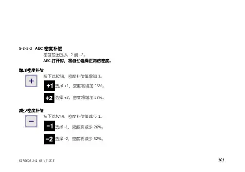
5-2-5-2 AEC密度补偿密度范围是从-2到+2。
AEC打开时,将自动选择正常的密度。
增加密度补偿按下此按钮,密度补偿值增加1。
选择+1,密度将增加26%。
选择+2,密度将增加52%。
减少密度补偿按下此按钮,密度补偿值减少1。
选择-1,密度将减少26%。
选择-2,密度将减少52%。
5-2-6 APR操作5-2-6-1 介绍操作员可以使用APR功能,进行放射应用参数的编制。
参见插图5-5,可以为一项特定的检查将来所有的放射参数以协议的形式纪录下来。
APR特征如下:°§ kV, mAs, mA, mSec· 体位(PA前后,LAT侧面,OBL倾斜)· 接收器· 身体类型(小,中,大)· 焦点(大,小)· 电离室区域· 黑化度玲龙 XR 6000系统上总共可以编制270个协议。
出厂设置会给出主要的APR协议,其余APR协议为0kV,0mA,0mSec,无AEC和大焦点。
如果用户选择0值APR,则系统显示错误代码,且系统抑止指示灯闪烁。
如果用户调节0值技术参数,则系统自动跳至此技术参数的最低值,并从此点开始调节。
如果用户改变任何默认值(如kV,mA,mSec,或电离室区域),LCD显示器上的曝光部位图标将闪烁,这意味着用户将应用自定义的非APR协议进行曝光。
5-2-6-2 APR选择插图5-5APR选择体位体型曝光部位选择体位按此按钮共有3个体位可供选择,并按照AP/PA、侧面、倾斜顺序循环选择。
AP按钮用于AP或PA。
LAT按钮用于侧面。
OBL按钮用于倾斜。
身体类型按此按钮共有3种体型可供选择,并按照偏胖或大个子患者、中等身材患者、偏瘦或小个子患者的顺序循环选择。
此按钮为偏胖或大个子患者。
此按钮为中等身材患者。
此按钮为偏瘦或小个子患者。
身体曝光部位选择共有10个身体曝光部位可供用户选择。
每一个按钮都可以编制到具有不同的预先设置协议上。
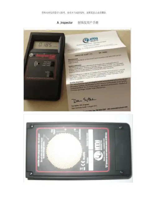
A ,Inspector 射线仪用户手册一、导言”Inspector”射线仪是用于健康和安全方面的仪器, 测量低水平的辐射。
它测量α、β、γ和x射线。
应用领域包括:1、探测和测量表面污染2、在接近放射性核素的地方, 监测可能的辐射量3、评估环境污染4、探测稀有气体和其它低能量放射性核素Inspector alert 具体参数Inspector Alert多功能射线检测仪技术参数1、探测器: 卤素淬灭剂GM管, 有效直径45mm, 云母窗密度1.5-2.0 mg/cm32、测量范围: mR/hr(毫伦/小时): 0.001—110.0,CPM( 每分钟计数) : 0—300,000μSv/hr(微希伏/小时): 0.01—1,100,CPS( 每秒钟计数) : 0—5,000,总计数: 1—9,999,0003、效率: Sr-90(546kev,2.3MeV βmax)约75%C-14(156kev βmax)约11%Bi-210(1.2MeV βmax)约64%Am-241(5.5MeV α)约36%4、灵敏度: 3500CPM/ mR/hr( 对于Cs-137)5、精度: ±15%6、温度范围: -10℃---+50℃7、电源: 1节9V碱性电池, 电池寿命 200小时8、尺寸重量: 150×80×30mm 350克( 含电池)二、”Inspector”如何测量辐射”Inspector”用一支盖革管-弥勒计数管来探测辐射。
每次当辐射经过盖革管时, 盖革管产生一个脉冲电流并引起电离。
这样每一次脉冲都被电路探测到且记为一个计数。
”Inspector”按照您选择的模式来显示读数。
由于放射性的随机性, 仪器检测到的计数每分钟都在变化。
取一段时间内的平均值更加精确, 时间越长越精确。
参见第三章”总量/加权操作模式”的细节。
预防措施要使仪器保持良好状态, 请小心使用和阅读下面内容:1、不要将仪器接触放射性表面或材料, 这样才不会污染”Inspector”。

慈星GE机型全电脑横机使用说明书警告:在操作前请仔细阅读宁波慈星股份有限公司前言首先,感谢您选择了我公司生产的全电脑横编织机,为了让您安全、有效地使用全电脑横编织机,特编写此手册,以供参考。
此操作说明书说明机器的概要,每一个控制指令,保养维修的注意事项;在安装、操作、维护和检查之前请仔细阅读机器制造商的操作说明书和其他辅助文件,只有在您完全理解这一系统并熟悉操作步骤以后才能操作机器。
请保留此说明书以便随时查阅,它将帮助您解决每一个您在操作时可能遇到的问题。
因产品升级、改良等而有可能产生本手册的记载内容与产品相异的情况;另外,本手册的记载内容有时也可能在未经预先通知的情况下更改,恕不另行通知。
最后由于编者水平有限,在本手册的编写过成中难免有错误和疏漏之处,敬请见谅!目录操作篇一安全使用机器说明1 关于机器安装注意事项 (4)2 关于安全操作的注意事项 (6)3 警告标语 (8)4 机器名牌 (10)二机器基本性能描述1 机器外观图 (11)2 机器规格 (12)3 机器噪音 (12)4 机器主要组成部分 (13)5各动作三角的功能与图解 (14)6 A、H、B位置图解 (16)7 选针器与选针脚对应图解 (22)8 针在针床中的排列 (23)9 卷布系统 (23)10 机头移出 (24)11毛刷 (25)12 纱嘴 (26)三、机器的基本操作1 设定花版的起始针 (27)2 穿纱引线 (27)3 夹线 (27)四、各页面操作使用说明A 文件管理 (28)B 花型管理 (33)I 运行 (37)K 连续织造 (48)维护篇一、各画面操作使用说明C 系统参数 (48)D 工作参数 (60)E 机头测试 (65)F 机器测试 (67)G 系统升级 (73)H 帮助 (73)J 关闭电脑 (73)二、维修保养 (75)三、横机电器部分 (84)一安全使用机器说明1 机器安装时的注意事项环境要求:为使机器处于良好的运作状态,请依据下列指示环境安置机台。

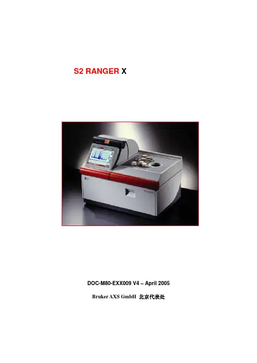
S2 RANGER X射线荧光光谱仪用户手册DOC-M80-EXX009 V4 – April 2005Bruker AXS GmbH 北京代表处S2 RANGER X 射线荧光光谱仪目录1 介绍 (4)S2 RANGER X射线荧光光谱仪 (4)EDXRF 能量色散X射线荧光光谱仪的基本原理 (4)2 启动 (5)S2 RANGER 开机 (5)S2 RANGER 关机........................................................................................................ ..7 S2 RANGER 触摸屏 .. (8)用户基本界面 ................................................................................................................ ..9 首次登录......... (10)3 触摸屏界面-总览 (11)进样器屏幕-介绍 (11)进样器屏幕- 一位进样器 (12)进样器屏幕- 28位自动进样器 (13)结果屏幕 (14)图形屏幕 (15)状态屏幕 (16)工具屏幕 (17)4 测量样品 (18)样品环 (18)一位进样器 (18)28位自动进样 (19)选择测量程序 (20)编辑样品编号 (21)开始测量-1位进样器 (22)开始测量-28位自动进样器 (24)测量错误 (25)5 结果数据库 (26)介绍 (26)高级查询 (28)6 深入分析 (29)图形屏幕 (29)对选定范围放大 (31)增加元素谱线 (32)EQUA-ALL 重新评估样品 (32)7 当前状态 (34)8 额外工具 (36)选项页 (36)用户编辑器页 (36)修改密码 (37)增加新用户 (39)修改用户权限.................................................................................... . (39)系统工具 (40)Bruker AXS (41)9 维护 (42)清洁光谱仪系统 (42)真空泵油 (42)打印机换纸 (43)空气过滤器....................................................................................................................... ..4410 故障查找 (45)开始测量 ................................................................................................................... ..45 与样品有关 (46)启动问题 (46)显示和触摸屏 (47)打印机........................................................................................................................... ..47 样品室门....................................................................................................................... ..47 进样 (47)计算机和外围设备 (49)软件问题 (49)与真空有关的问题......................................................................................................... ..50 不能获取数据.. (50)进样器屏幕的错误信息 (51)1 介绍S2 RANGER X射线荧光光谱仪S2 RANGER X射线荧光光谱仪是能量色散型X射线荧光光谱仪(EDXRF)。
INTRODUCTIONThese magnetic resonance (MR) protocols were developed by an expert consensus panel for use on General Electric (GE) MR imaging machines, and were developed for high-end platform scanners with multichannel phased array coils and parallel reconstruction capabilities. The protocols are divided into 3 sections:•Body MR imaging•Body MR angiography•Central nervous system (CNS) MR imagingThe protocol parameters can generally be adapted to work with other software platforms or releases and hardware configurations but may require small modifications that can be made by a knowledgeable and experienced MR technologist. Scan times may increase in some circumstances.These protocols provide field strength–specific parameters for 1.5T and 3T. Attention has also been given to patient preparation, streamlining the exam, and making the best use of contrast material, whether it is a standard gadolinium-based extracellular fluid agent, a high-relaxivity gadolinium-based contrast agent (GBCA), such as MultiHance® (gadobenate dimeglumine [Gd-BOPTA]), or agents with hepatobiliary uptake such as Eovist®(gadoxetic acid) and MultiHance®.Each protocol contains a brief description of patient preparation, special notes on coil choice and placement, suggestions for contrast dose and administration rate, and suggestions concerning timing of fluoroscopic triggering, if appropriate.The consensus panel consisted of the following experts in radiology:Thomas Grist, MD University of Wisconsin School of Medicine and Public Health, Madison, Wisconsin Mark C. DeLano, MD ̶ Michigan State University, Advanced Radiology Services, PC, Grand Rapids, Michigan Scott B. Reeder, MD, PhD ̶ University of Wisconsin School of Medicine and Public Health, Madison, Wisconsin Howard A. Rowley, MD ̶ University of Wisconsin School of Medicine and Public Health, Madison, Wisconsin Steffen Sammet, MD, PhD, DABR, DABMRS, FAMP ̶ The University of Chicago Medical Center, Chicago, Illinois Megan E. Vadnais, BSRT, (R)(MR) ̶ University of Wisconsin School of Medicine and Public Health, Madison, WisconsinDisclaimerThe content and views presented in this educational activity are those of the authors and do not necessarily reflect those of Medical Education Resources, ABC Medical Education, and/or Bracco Diagnostics Inc. The authors have disclosed if there is any discussion of published and/or investigational uses of agents that are not indicated by the US Food and Drug Administration (FDA) in their presentations. The protocols presented here were developed for pediatric and adult patients of average weight.Before prescribing any medicine, primary references and the full prescribing information for each product should be consulted. Any procedures, medications, or other courses of diagnosis or treatment discussed or suggested in this activity should not be used by clinicians without evaluation of their patient’s conditions and possible contraindications or dangers in use, review of any applicable manufacturer’s product information, and comparison with recommendations of other authorities. The information presented in this activity is not meant to serve as a guideline for patient management.Off-Label StatementThis educational activity contains discussion of published and/or investigational uses of agents that are not on-label by the FDA. The opinions expressed in the educational activity are those of the faculty. Please refer to the official prescribing information for each product for discussion of approved indications, contraindications, and warnings. Further, participants should critically appraise the information presented and are encouraged to consult appropriate resources for any product or device mentioned in this activity.MR Protocols for Body MR ImagingContrast timing is extremely important for abdominal MR imaging, particularly for high-quality liver imaging. We recommend the use of fluoro-triggering or “SmartPrep” methods rather than the use of a timing bolus.All body MR imaging protocols presented here were developed by Scott B. Reeder, MD, PhD, Steffen Sammet, MD, PhD, DABR, DABMRS, FAMP, and Megan E. Vadnais, BSRT, (R)(MR) for 1.5T and 3T systems. Specific protocols include:•Abdomen‒ Generic Abdomen Pelvis 1.5T and 3T‒ Appendicitis Noncontrast 1.5T and 3T‒ MR Enterography 1.5T and 3T•Liver‒ Liver/Pancreas Extracellular Agent 1.5T and 3T‒ Liver/Pancreas Hepatobiliary Agent 1.5T and 3T‒ Magnetic Resonance Cholangiopancreatography (MRCP) Noncontrast 1.5T and 3T‒ Diffuse Liver Disease 1.5T and 3T•Pelvis‒ Generic Pelvis 1.5T and 3T‒ Female Pelvis Malignant 1.5T and 3T‒ Female Pelvis Benign 1.5T and 3T‒ Uterine Anomaly 1.5T and 3T‒ Rectal Cancer 1.5T and 3T‒ Perianal Fistula 1.5T and 3T‒ Prostate 1.5T and 3T•Adrenal and Renal‒ Adrenal 1.5T and 3T‒ Renal 1.5T and 3TGeneral Notes•Intravenous access should be obtained with an 18- to 22-gauge needle•We suggest the use of a contrast injector and a saline flush of a minimum of 20 to 30 mL at the same injection rate as the contrast injection (1.5-2.0 mL/sec)•Breath-holding is essential for good image quality for thoracic or abdominal MR imaging. Precontrast scans should be used to ensure that the patient can both breath-hold adequately and understand the instructions. We recommend breath-holding at end-expiration (end tidal volume)•When parallel imaging is used, care must be taken to increase the field of view sufficiently to avoid residual aliasing artifact. This is generally more often a problem for coronal imaging, which may require placing the arms over the head or elevating the arms by the patient’s side•In patients with renal failure, consider using a half-dose (0.05 mmol/kg) of a high-relaxivity Group II contrast agent such as MultiHance® (gadobenate dimeglumine), particularly at 3TMR Protocols for Body MR AngiographyAll protocols should use Fluoro-Triggered (FT) magnetic resonance (MR) angiography fluoroscopic imaging for bolus detection. MR imaging protocols for MR angiography presented here include 1.5T and 3T systems, and were developed by Thomas Grist, MD, and Megan E. Vadnais, BSRT, (R)(MR) for the following procedures:•Cardiac MRA–Cardiac Basic Anatomy and Function 1.5T and 3T–Pulmonary Artery 1.5T and 3T–Pulmonary Vein Mapping 1.5T and 3T•Thoracic MRA–Thoracic Aorta MRA 1.5T and 3T–Gated Thoracic Aorta 1.5T and 3T•Abdominal MRA–Contrast-enhanced MRA Abdomen 1.5T and 3T–Noncontrast-enhanced MRA Abdomen 1.5T and 3T–Thoracoabdominal Aortic Aneurysm MRA 1.5T and 3T•Peripheral MRA–Lower Extremity Contrast-enhanced MR Venography (CE MRV) 1.5T and 3T–Runoff Abdomen to Lower Extremity MRA 1.5T and 3T–Peripheral Runoff Noncontrast 1.5T and 3T–Arteriovenous Malformation (AVM) Evaluation 1.5T and 3TThe rationale for the patient preparation for contrast-enhanced MR angiography is based on a hypothetical generic patient. Individual protocols may include important variations and will be delineated in the specific protocol. General Notes•Intravenous access should be obtained with an 18- to 22-gauge needle, inserted preferably in the antecubital fossa. Right side is preferred (when possible) for thoracic or carotid MR angiography•Use respiratory bellows – gating parameters:–R-R intervals = 2-3–Trigger point = 40%–Trigger window = 30%–Delay = minimum•The basic sequences recommended are intended to achieve both anatomic localization and high-quality anatomic imaging to complement the angiographic sequences that are performed. These include:–3-plane localizer–Coronal single-shot fast spin-echo (FSE)–Axial T2 FSE (respiratory triggered)–3D (three-dimensional) contrast-enhanced MR angiography FT (precontrast-practice breath-hold)–3D contrast-enhanced MR angiography FT (postcontrast)–3D contrast-enhanced MR angiography FT (2nd postcontrast)–Axial fast spoiled gradient-echo postcontrast fat-saturated•A power injector is highly recommended with a minimum of 20- to 30-mL saline flush delivered at the same injection rate as the contrast injection•Breath-holding is critical to good image quality for thoracic or abdominal MR angiography. Precontrast or practice scans help ensure that the patient can both breath-hold adequately and understand the instructions•When parallel imaging is used, care must be taken to not have wraparound artifact on the vascular structures. This generally requires prescribing a large field of view beyond the body wall, and for abdominal imaging, it requires placing the arms over the head or elevating the arms at the patient’s side. When performing the calibration scan, overprescribe by one-fourth the area of interest in the superior and inferior directions to reduce scan cutoff. Calibration scans are performed in the axial plane MR Protocols for Central Nervous System (CNS) MR Imaging Newer hardware and software platforms at both 1.5T and 3T allow efficient protocol options for a wide range of CNS indications. This section suggests multiple consensus methods for optimizing examination of patients undergoing MR imaging in the CNS. Core sequences in each protocol are identified, and their aggregate use constitutes a complete examination for each protocol. Alternative sequences of interest are included for emerging technologies, specific target anatomy, or subspecialty preference.1.5T and 3T CNS MR imaging protocols presented here were developed by Howard A. Rowley, MD, Mark C. DeLano, MD, and Megan E. Vadnais, BSRT, (R)(MR) for the following procedures:•Brain–Routine Adult Brain 1.5T and 3T–Brain Neck Magnetic Resonance Angiography (MRA)/Magnetic Resonance Venography (MRV) 1.5T and 3T –Motion Brain 1.5T and 3T–Routine Stroke Fast 1.5T and 3T–Hyperacute Stroke Brain 1.5T and 3T–Tumor Brain 1.5T and 3T–Multiple Sclerosis Brain 1.5T and 3T–Pediatric Brain 1.5T and 3T–Epilepsy Brain 1.5T and 3T•Specialty Brain–Hydrocephalus Brain 1.5T and 3T–Cerebrospinal Fluid Flow 1.5T and 3T–Pituitary 1.5T and 3T–Cranial Nerves/Internal Auditory Canals 1.5T and 3T–Vessel Wall 1.5T and 3T•Head and Neck–Orbits 1.5T and 3T–Soft Tissue Neck 1.5T and 3T–Sinuses/Face 1.5T and 3T•Spine–Cervical Spine 1.5T and 3T–Lumbar Spine 1.5T and 3T–Thoracic Spine 1.5T and 3T–Routine Total Spine 1.5T and 3T–Focused Total Spine 1.5T and 3T–Specialty Spine 1.5T and 3T–Brachial Plexus 1.5T and 3T–Lumbar Plexus 1.5T and 3TGeneral CNS Protocol Notes•Standard brain. There are multiple approaches to obtain various tissue parameter weightings at both1.5T and 3T, such that “standard” imaging refers more to the general-purpose nature of the protocolrather than the core sequence choices. The core preferences of our consensus panel are indicated within each protocol•T1.Six techniques for obtaining T1-weighting are included: spin echo (SE), fast spin echo (FSE), T1 fluid-attenuated inversion recovery (T1-FLAIR), 3D IR-prepared FSPGR (BRAVO), 3D T1 CUBE, and magnetization transfer (MT)–SE is the T1 reference standard for image contrast at 1.5T, although the other sequences have unique advantages and are included as options. Due to T1 prolongation at 3T and associated loss of gray-white contrast there is no consensus standard for T1-weighting, and many sites use inversion recovery preparation to restore tissue contrast–FSE with its intrinsic magnetization transfer effects results in decreased gray-white contrast but may depict contrast enhancement to better advantage–T1-FLAIR and BRAVO are inversion prepared, facilitating excellent gray-white differentiation but with the potential disadvantage of inconspicuous contrast enhancement due to the marked precontrast hypointensity of many lesions and subsequent isointensity to surrounding brain postcontrast –BRAVO, as a standard 3D sequence, has the key advantage of multiplanar reconstruction capability of the isotropic data sets, and excellent gray-white contrast desirable for most applications –T1 CUBE. This T1-weighted FSE-based volumetric sequence can be performed either before or after contrast. Beyond the usual 3D attributes (such as high resolution and multiplanar reconstructions), it has particular advantages postcontrast, where it provides black blood imaging, supports fat saturation, and shows outstanding tissue contrast for enhancing lesions. T1 CUBE is suitable for routine brain imaging and also orbital, cranial nerve, and vessel wall imaging exams. Many sites now use T1 CUBE as a supplement to postcontrast T1 BRAVO and other sequences–MT is an optional feature that can be added to increase contrast enhancement conspicuity on SE imaging, but at the cost of increased SAR and decreased gray-white distinction•T2. Most sites use FSE sequences rather than SE. PROPELLER is effective for dealing with patient motion, and is the primary FSE sequence used at many sites. Some users add fat saturation to T2 imaging as an option•T2-FLAIR.Improves lesion detection particularly at the brain-CSF interface. When done as the first sequence postinjection, postcontrast T2-FLAIR imaging effectively inserts a time delay for subsequent T1-weighted scans, which improves lesion detection on subsequent T1 imaging. The T2-FLAIR images also have some intrinsic T1 contrast that allows visualization of both edema and enhancement on one sequence for many lesions. Both 2D and 3D T2-FLAIR sequences are commonly performed, with the advantage of multiplanar reconstruction capability and fewer CSF pulsation artifacts of the 3D CUBE •Susceptibility. Due to the reduced susceptibility weighting of FSE methods, a T2*-GRE sequence can be added as an option to detect blood products and calcium. The SWAN sequence has been shown to more sensitively detect subtle areas of blood and calcium and has become a common protocol choice•Diffusion. Most brain protocols include a diffusion-weighted imaging sequence that is useful for stroke, infection, and tumor imaging. Apparent diffusion coefficient maps should be included to assess T2 shine-through. In areas near the skull base or orbits, PROPELLER DWI can be a good option to reduce signal pile-up and geometric distortion artifacts•Perfusion. Dynamic susceptibility contrast, perfusion-weighted imaging is becoming increasingly important and can provide clinically significant information regarding blood volume and/or transit time for both stroke and tumor imaging. Arterial spin labeling is also an option for assessing cerebral blood flow at 3T, but must be obtained precontrast•Contrast. The protocols presented here do not list separate imaging sequences for postcontrast imaging; rather, the T1-weighted sequence of choice is typically repeated after contrast agent administration. Most neurologic sequences with contrast are acquired with at least a 3- to 5-minute delay after injection to optimize visualization of disorders of the blood-brain barrier. Some protocols use more than one sequence “family” postcontrast, such as T2-FLAIR, T1-BRAVO, and T1-CUBE Fat Sat due to their complementary information. Many centers prefer routinely acquiring such volumetric series postcontrast to facilitate retrospective multiplanar reconstructions, treatment planning, and neuronavigation applications. T2-FLAIR is an excellent complement to T1 series, and may be done first postcontrast to intentionally provide a time delay before the T1 series are acquired. The method of injection is not important in these cases, and manual injection is typically used. However, power injectors are needed for contrast-enhanced MR angiography and perfusion imaging. Rates of injection vary, but 4 to 5 mL/sec is standard for perfusion, and 1.5 to 2 mL/sec is used for MR angiography. Dosing is weight based and at 0.1 mmol/kg for most protocols aimed at standard extracellular fluid distribution. The dose for an individual injection may be lower for first-pass MRA or perfusion exams, where a split-dose protocol can often be used, keeping overall dose within the standard 0.1 mmol/kg guideline. The ACR has recommended that the lowest dose feasible be used for diagnostic purposes. Because standard dosing recommendations are mostly influenced by lean body mass, and ECF volume in fatty tissues is low, some sites cap the upper limit of contrast for heavier adults at 20 mL total, especially when a high-relaxivity agent is being used.A useful contrast dose calculator (“GadCalc”) is available at https:///contrastCorner/ gadcalc.php and is also available for free download at the Apple and Droid App Stores.。
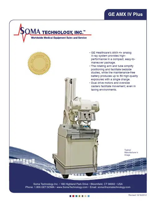
,★S L A R AO RN T ★M T EO GY I N★★Y★★Soma Technology Inc. • 166 Highland Park Drive • Bloomfield, CT 06002 • USATypicalManufacturer’s Imagepositioning and facilitate bedside studies, while the maintenance-free battery produces up to 50 high-quality exposures with a single charge.• D ual drive motors and oversizecasters facilitate movement; even in taxing environments.GE AMX IV PlusSpecificationsDimensions• H eight: 70 inches (1778 mm) for Models 2169360−6, 2236420−6, and 2275938−6, −12,−13, −14, −15; all others 76 inches (1930 mm).• W idth: 25−3/16 inches (640 mm)• Length: 45−3/8 inches (1153 mm)• Weight: 1080 pounds (490 kg) Environmental Limits1. Operating temperature range: 59 to 100 Degrees Fahrenheit (15 to 38 Degrees Celsius) at 80% non−condensing humidity.2. Storage temperature range −40 to +140 Degrees Fahrenheit (−40 to +60 Degrees Celsius)3. Maximum operating altitude: 8,000 feet (2440 meters).Battery Specifications• N ine 12.9 volt batteries connected in series provide approximately 116 volts at full charge. Battery CapacityThe AMX−4+ battery capacity can be measured by one of the following five methods. All capacities are measured after the AMX−4+ has been charged to the “CHARGE COMPLETE” state. Available capacity as stated applies only to new battery sets free of defective cells. Capacity may decrease as the battery nears the end of its useful life. Method 1: ExamsThe AMX−4+ batteries will provide capacity for more than 20 typical EXAMs. An “EXAM” is defined as:− Two 70 kVp, 10 mAs X−ray exposures including: > 7 seconds of prep (rotor and filament drive)> 25 seconds of field light− 5 minutes of drive time− 9 minutes of idle timeThe formula in the “VARIED USAGE” section can be used to determine the number of total EXAMs available for usage regimes different from this typical case.Method 2: X−ray ExposuresThe AMX−4+ batteries will provide enough capacity for 165 or more 100 kVp, 100 mAs X−ray exposures. Each exposure includes 4 seconds of prep (rotor and filament drive) time and 30 seconds of idle time for battery recovery. This number may be reduced by additional idle time required for X−ray tube cooling.Method 3: Drive TimeThe AMX−4+ batteries will provide enough capacity for 140 minutes of continuous drive time. This time is typically independent of driving conditions, however, it may be reduced if a significant portion of the drive is on carpeting or up ramps.Method 4: Idle TimeThe AMX−4+ batteries will provide capacity for 23.3 hours of continuous idle time. “Idle” is the time when the AMX−4+ is ON but not being used.Method 5: Varied UsageFor varied usage, the AMX−4+ batteries will provide capacity according to the following formula:{ (idle time in minutes ) _ 3} +{ (drive time in minutes ) _ 30} +{ ( field light time in minutes ) _ 25 } +{ ( prep time in minutes ) _ 30} +{ ( exposure energy* ) _ 2.17} = 4200*exposure energy = cumulative { ( kVp _ mAs ) _ 1000 }EXAMPLE: Assume one desires to estimate the number exams available from an AMX−4+ used in a particular pediatric ward. It is determined that a typical exam for this case is comprised of:− Two 70 kVp, 0.8 mAs X−ray exposures including: > 3 seconds of prep> 15 seconds of field light− 1 minute of drive− 5 minutes of idleUsing the above formula we can estimate the number of exams as follows:each EXAM uses { (5 idle minutes ) _ 3} + { (1 drive minutes ) _ 30} +2 x [ { (15 _ 60 field light minutes ) _ 25} + { (3 _ 60 prep minutes ) _ 30} +{ ( (70 kVp _ 0.8 mAs ) _ 1000 ) _ 2.17} ] = 60.7 therefore the total number of typical EXAMs available is: 4200 _ 60.7 = 69Movements• T ube vertical movement measured at the focal spot (arm extended):a. R ange at least 46.5 inches (1181 mm)for Models 2169360−6, 2236420−6 and2275938−6, −12, −13, −14, −15; all others atleast 52.5 inches (1334 mm).b. L owest position 26.1 inches (663 mm) max.from floor.c. H ighest position 72.6 inches (1844 mm) min.from floor for Models 2169360−6, 2236420−6and 2275938−6, −12, −13, −14, −15; allothers 78.6 inches (1996 mm) min. from floor.• T he horizontal movement measured at the focal spot relative to column face is 24 inches (610 mm) minimum, to 40 inches (1016 mm) maximum.• T ube Column rotation measured from horizontal arm latch is +/−270 degrees.• T ube and yoke rotation around Horizontal Arm measured from tube port down position:a. Range 360 degrees;b. D etent locations0, +/−90, and +/−180degrees.• T ube Trunnion rotation measured from tube port down position:a. Range 120 degrees;b. Forward 110 degrees;c. Backward 10 degrees;d. Detent 0 degrees, and 90 degrees.• C ollimator Rotation measured from the front of the collimator with the tube port facing down:a. Range 180 degrees;b. Right 90 degrees;c. Left 90 degrees;d. Detent 0 and 90 degrees.Moving Efforts• M oving efforts with locks mechanically off (that is, energized electrically):a. V ertical tube motion: 12 pounds (53 Newtons)maximum, measured going up or down; 15pounds (67 Newtons), measured over last 4inches (102 mm) of travel.b. H orizontal tube motion: 14 pounds (62.3Newtons) maximum, measured going in orout.c. T ube Column rotation: 15 pound−feet (20.3Newton−meters) maximum. d. T ube and yoke angulation around horizontalArm: 10 to 20 pound−feet (14 to 27 Newton−meters) to disengage from detent, 6 to 18pound−feet (8 to 24 Newton−meters) to rotatebetween detents.e. T ube rotation in yoke: 7 to 30 pound−feet(9.5 to 41 Newton−meters) to disengage fromdetent, 4 to 20 pound−feet (5 to 27 Newton−meters) to rotate between detents.• M oving efforts with locks mechanically on (that is, not energized electrically):a. V ertical tube motion: 15 pounds (67 Newtons)minimum, 32 pounds (142 Newtons)maximum; measured going up or down.b. H orizontal tube motion: 10 pounds (44.5Newtons) minimum, 28 pounds (125Newtons) maximum; measured going in orout.c. T ube Column rotation: 25 to 40 pound−feet(34 to 54 Newton−meters).Drive SpeedThere are two speeds: Drive Speed with the horizontal Tube Arm secured for transport, and Maneuvering Speed with the horizontal Tube Arm removed from the Transport Latch.Drive speed is measured on a smooth, hard and level surface. Speed will be reduced by inclines, carpeted or soft surfaces.• D rive Speed is 264 feet (6705 mm) per minute +/− 25%;• M aneuvering Speed is 30% to 60% of drive speed.Tube Unit RatingsTube Housing and Insert Specifications are given in Direction 46−017226, Tube Ratings, HRT 50 and 60 Hz., or in 2236721−100, Product Data Sheet Maxiray 75 TH 11 X−ray Tube. Also, refer to note on maximum allowable kVp and mAs ratings in 2166913−1EN AMX−4+ Operating Manual.cont’dGenerator Operator IndicatorsCheck for proper operation of tones or buzzers and labels as required by regulations. Reference “Generator Operator Indicators” in Tab 3 of Direction 46−013894, System Field Test for HHS.1. X−ray on indicator lights during an exposure.2. Audible tone occurs during exposure.3. A udible tone occurs with safety timedtermination of AEC exposures.4. S afety timed termination of AEC exposuresrequires resetting before taking anotherexposure.5. X−ray warning label is legible.kVp Accuracy1. R ise time of the kVp wave form from 10% to90% of the maximum kVp is 1.2 millisecondor less.2. F all time of the kVp wave form from 90% ofthe maximum kV to 20 kV is 2.5 millisecondsor less.3. A ccuracy of the kVp wave form to selectedkVp is +/− 8% of the value displayed on theoperator panel for the first 20 ms and +/− 5%after 20 ms. Accuracy applies within the rangeof the bar graph battery charge indicator. Note: These specifications do not apply to switching transients which occur during the first millisecond and the last millisecond of an exposure. Test MethodUse a Keithley Non−Invasive kVp Divider (Model 35080A with Deviation 535 or Model 35080B, both using Mobile Filter Pack Plus 37946C and optional Low Range Filter Pack 38237C). A Triad 35050A Dosimeter can also be used to provide digital readout of corrected kVp values. No other substitutions for non−invasive kVp Dividers are approved!The set−up procedure and linear correction curves (non−Triad systems) for using the Keithley divider are covered in Section 3 of Direction 46−017561 HHS Control and Tube Assembly Tests and Keithley’s Operation and Maintenance manuals. AlternateUse the GE C1515A Invasive Bleeder. If this method is used, the unit should be calibrated and verified with this meter.Note:I f an attempt is made to verify a unitcalibrated with a C1515A bleeder with eitherof the above Keithley Non−Invasive dividers,kVp readings will read 5−7 kVp higher thanwhen read with the C1515A. This is dueto impedance changes in the high voltagecircuit with the bleeder removed from thecircuit and due to frequency compensationerrors present using the C1515A dividerwith the AMX−4+ waveform. The procedurefor connecting the C1515A High Voltagedivider is covered in Direction 46−013288Bleeder, High−Voltage Dual Type T8005Gand C1515A Connection ... Applications, andDirection 2196272−100, High Voltage CableInstallation and Troubleshooting Procedures. Make exposures and calculations as described in “Technique Accuracy − kV/mA” in Tab 3 of Direction 46−013894 System Field Test for HHS. Metering AccuracyAccuracy of mAs is the integral of X−ray tube emission current between the time at which the kV wave form reaches 75% of the indicated peak value at the beginning of an exposure and the time at which it falls to 75% of the indicated peak value when the exposure is terminated. Actual mAs shall match selected mAs within +/−10%. Preferred Test MethodThis is an indirect procedure which verifies accuracy of the mAs metering circuitry and mAs calibration. Measuring mAs Metering Accuracy is done by injecting 100 mA into the mAs integrating circuit and comparing the response with a meter installed in the circuit. Reference Direction 2173223−100, AMX−4+ Calibration − familiarity with this direction is assumed. Also reference “Technique Accuracy − mAs” in Tab 3 of Direction 46−013894, System Field Test for HHS.1. Enter mAs calibration and install meter.2. A t the prompt ENTER VALUE compare meterreading with displayed reading.3. C orrect reading to include meter accuracybefore comparing with requirements. Note:A ccuracy of mA reading at the approximate 100 mA test condition is _ 0.1 mA. Meteraccuracy must be added to the mA readingbefore making judgment on the final reading.ReproducibilityThe coefficient of variation for radiation output is less than 0.045 for successive exposures having constant technique factors. Coefficient of variation is measured and calculated as described in “Reproducibility of Exposure” in Tab 3 of Direction 46−013894, System Field Test for HHS. This applies to all units for non−AEC mode − reference the procedure “for exposures made without the use of A.E.C.” For units equipped with Mobil−AID, also reference the procedure “for exposures made with an A.E.C.”Beam QualityThe half−value layer of the useful beam at 80 kVp shall not be less than 2.5 millimeters of aluminum. This requirement differs slightly from and supersedes NCRP 33. The specific test point is at 80 kVp requiring a half value layer of 2.5 millimeters of aluminum. This applies to systems manufactured before June 10th, 2006. For systems manufactured on or after June 10th, 2006 the following new regulation applies; The half−value layer of the useful beam at 80 kVp shall not be less than 2.9 millimeters of aluminum. The specific test point is at 80 kVp requiring a half value layer of 2.9 millimeters of aluminum. Reference the System Rating Plate to determine manufactured date. Note: The rating plate shows month and year only. For systems manufactured during June, 2006 you must verify the manufactured date in the GE GIB database. Contact your local Service Representative for assistance.Test MethodThe procedure for measuring Beam Quality is presented in “Beam Quality (Half Value Layer)” in Tab 4 of Direction 46−013894 System Field Test for HHS. The following noted exceptions to that procedure apply for the AMX−4+:1. S elect initial technique factors of 80 kVp and20 to 48 mAs.2. W hen making an exposure without theabsorber, adjust mAs so that the radiationmeter reading contains three significant digits.3. U se an AMX−4 absorber 46−173632G2 in thecollimator rails.> F or systems manufactured On or AfterJune 10th, 2006 add additional aluminumfiltration from the HVL Attenuator set part #46−194427P274 found in the HHS Kit part #46−303879G1 or 46−303879G2. Total testfiltration = 3.1 mm of Aluminum. Affix theseplates to the AMX−4 absorber with tape.Ensure the tape is not in the usable beampath.> F or tube changes there is an additional 1.2 mm Aluminum cup added to the X−RayTube. This cup snaps onto the collimatormounting plate and is easily identified sincethe tube glass port is not visible. This cupmust be present and retained for systemsmanufactured On or After June 10th,2006. Likewise this cup if provided with thereplacement tube it must be removed forsystems manufactured before June 10th,2006. Reference the system rating plateaffixed to the AMX unit.cont’d。

GEMeasurement & ControlISOVOLT Lynx 160 / 320New Generation Stationary X-ray GeneratorThe ISOVOLT Lynx is the first in a new generation ofstationary X-ray machines from Inspection Technologies.It represents a major advance in X-ray generator technology,incorporating the latest electronics and digital conceptsto allow greater performance and reliability. It has beendesigned to align with the optimized performance of othercomponents in the X-ray inspection imaging chain for a widerange of applications including the automotive, aerospaceand metals manufacturing sectors, for tasks such as theinspection of welds, composites and castings, as well as in 3Dcomputed tomography and metrology. It will be of particularinterest to system integrators working in both the industrialand scientific sectors.ISOVOLT Lynx GeneratorThe journey has just begun ...GE introduces the next generation of stationary X-ray machines with the new ISOVOLT Lynx, which is one of the most significant innovations in X-ray generation for the past 10 years.There have been enormous strides in imaging and tube technology over the past decade but the generator technology has been pretty static. By leveraging many of the concepts employed in the GE healthcare business, using their latest state-of-the-art technology, we have been able to develop this new industrialized version for industrial customers. This development has required us to create an application map for each potential generator application and then define the generator specifications needed to meet and optimize the tube, imaging and inspection standard requirements for that application.1. ISOVOLT Lynx GeneratorThe result is a flexible and versatile generator platform which offers high reliability and performance across a very broad application spectrum. It is also a very scalable platform, which will allow us to meet future integration and monitoring requirements and the needs for higher energies, even up to 600 kV. In a first stage the ISOVOLT Lynx will be available as 160 kV and 320 kV version.Both generators offer enhanced maintenance freeoptions: maintenance free high voltage plugs on thegenerator side and new maintenance free bipolar tubehousing for the 320 kV version. The integration into fullyautomated systems for in-line operation has also beenoptimized. The optional ISOVOLT Lynx Remote Controlor the ISOVOLT Lynx Control ensure a simpleconfiguration, control and operation.Features & BenefitsR e l i ab i l it ySafety&Performan ceF l e x i b i l i t yS e rv i ceability&CostofE a se o fComplianceD i agnosticsOwnershipI n te g ra t i o nReliability Safety & Compliance PerformanceFeature Benefits State-of-the artscalable, high-frequencyMOS-FET driven, power electronics designed Feature BenefitsIntegrates all safetyrelevant mechanismsFeature BenefitsNominal power45 mA*, 4500 W*Safety&Performan ceF l e x i b i l i t yS e rv i ceability&CostofComplianceD i agnosticsOwnershipI n teR el i a bi l i t yf e t y&r v i c ea b i l i t y&C os tofEaseofC o m p l ia n cD i a gn o s t i c sOw ne r shipIntegrationP e r f o r m a n ceFlexibilityServiceability&C o s to fDiagnosticsOw n er s h i pCost of Ownership Ease of IntegrationAssisted X-ray tubecharacteristicsrecognition and digitalparameter adjust-Quick installation procedureFlexibilityFeature BenefitsMaintenance freeoptionNo need for periodic highvoltage plug maintenanceSealed high voltage No spillage, transport andDiagnosticsFeature BenefitsImproved CPUplatform, Onlinemonitoring and datarecording of relevantsystem parameterBetter fault interpretationData collectionOutlook for future:statistical data analysis andpredictive monitoringServiceabilityFeature BenefitsField Replaceable Units(FRU) ConceptQuick replacement of mainmodules, short downtimes(for simplified spare partsmanagement, fast turn-around-time)Simplified trouble-Quick determination of sys-&P er f o r m a n c eF l e x i b i l i tySc e2. ISOVOLT Lynx ControlA user-friendly, multi-language control features a clear full-colour graphicaldisplay with touch screen, that allows simultaneous readings of set and actual operating parameters. Embedded in an ergonomic and rugged desktop or optional 19” rack mounting housing, full control of X-ray operation features, service and system configuration features, online monitoring of relevant system parameters is established. Intuitive guidance through diverse menus as well as unmistakable messages for clear interventions are provided with this module.Features such as free configurable exposure programs, or special programs for constant power, constant current and manual operation cater for individual demands for radiographic or radioscopic inspections. The multi-lingual user display with 16 different languages and extended character sets for Japanese, Cyrillic and Chinese enables comprehensible and simple interaction.ISOVOLT Lynx provides automatic and manual warm-up modes for optimized tube conditioning. A special extended warm-up mode safeguards tube performance under severe conditions and setups.3. ISOVOLT Lynx Remote ControlDesigned for the needs of system integrators this PC based tool provides full control over all ISOVOLT Lynx operation, service and diagnostics features.It can be installed on every WIN 7 or WIN XP PC and can beconnected via a USB/RS-232 cable with the ISOVOLT Lynx generator.Alongside with the optional fail-safe E-Stop Control Box, ISOVOLT Lynx Remote Control establishes a full PC based generator control and management platform.WL 5000 RE OW 4002OL 4503OLK 50Voltage dividerMaintenance free tube housing Junction kits and safety devicesDiaphragms Column standX-ray TubesISOVOLT Lynx supports a comprehensiveportfolio of monopolar and bipolar X-ray tubes from different suppliers.Please contact your sales representative for consultation on X-ray tube selection.AccessoriesSafety devices• Primary interlock switch • Alarm box • Switch box• Flash- and warning lamps • Country specific safety kitsHV cables• In different standard lengths, with quick-lock or flange connections with rubbercone plugs or maintenance free plugs.Dosimetry and calibration kits • Voltage divider Pumps and coolersSee pictures on this pageTechnical Specifications* 40 mA permanent operation, limited to peak operation** Limited to tube specification, temperature and operating mode *** At constant temperature level© 2012 General Electric Company. All Rights Reserved. Specifications are subject to change without notice. GE is a registered trademark of General Electric Company. Other company or product names mentioned in this document may be trademarks or registered trademarks of their respective companies, which are not affiliated with GE.GEIT-30222EN (12/12)Regional OfficesEuropeAmericasAsiaGermanyRobert Bosch Strasse 3 50354 Huerth +49 2233 6010 Lotzenäcker Strasse 4 72379 Hechingen (RVI only)+49 (0) 7471 9882 0Niels-Bohr-Strasse 7 31515 Wunstorf P.O. Box 6241 (RT only)31510 Wunstorf +49 5031 172 0Bogenstrasse 41 22926 Ahrensburg (RT only)+49 4102 807 117United Kingdom892 Charter Avenue Canley Coventry CV4 8AF +44 845 130 3925France68, Chemin des Ormeaux Limonest 69760+33 47 217 9216SpainSan Maximo, 31, Planta 4A, Nave 6 Madrid 28041+34 915 500 59 90United States50 Industrial Park Road Lewistown, PA 17044+1 866 243 2638 (toll free) +1 717 242 0327721 Visions DriveSkaneateles, NY 13152 (RVI only)+1 888 332 3848 (toll free) +1 315 554 2000 ext. 1BrazilAv. Maria Coelho Aguiar, 215 Building C, 6th floorJd. Sao Luiz - Sao Paulo - SP CEP 05804-900 – Brazil +55 11 3614-1840China5F, Building 1, No.1 Huatuo Road, Zhangjiang High-Tech Park, Shanghai 201203+86 800 915 9966 (toll-free) +86 (0) 21-3877 7888Unit 1602, 16/F Sing Pao Building 101 King’s Road North Point Hong Kong+852 2877 0801JapanHarumi Island Triton Square Office Tower X 1-8-10, Harumi, Chuo-ku, Tokyo 104-6023Tel: +81 3 6890 4567Fax: +81 3 6864 1738GE Sensing & Inspection Technologies has sales and service offices all over the world. Below are some of our locations. Visit for a complete listing. • Berchem, Belgium • Alzenau, Germany• Burford, United Kingdom • Moscow, Russia • Bucharest, Romania • Prague, Czech Republic • Stockholm, Sweden •Milan, Italy• East Perth, Australia • Singapore • Dubai, UAE• Buenos Aires, Argentina • Mexico City, Mexico • Airdrie, Alberta, Canada • Toronto, Ontario, Canada •Montreal, Quebec, Canada。
手足斜位55100 6.3551008551008尺桡骨正位55100555100 6.3551008尺桡骨侧位55100555100 6.3551008肩关节正位601004060100406010050膝关节正位55100 6.35510085510010膝关节侧位55100 6.35510085510010腹平片正位652008065200807520080腹平片侧位703201607032016080320160骨盘正位602004060200506520063颈椎正位702003270200327020040颈椎侧位702003270200327020040颈椎双斜位702003270200327020040腰椎正位652005065200637020080腰椎侧位702501007025012580250160腰椎斜位652005065200637020080说明:该表中所给参数为常用部位摄片时的参考条件,操作者可以根据医院具体使用情况(包括一声的看片习惯、使用不同的胶片、不同的洗片液)来灵活改变摄片的条件。
补充说明:1. 若在拍摄过程中片子整体“过黑”,首先要降低mAs,如若降低mAs后片子仍然比较“黑”,则要降低kV值。
2. 若在拍摄过程中片子整体“过白”,首先要增加kV值,如若增加kV值后片子仍然比较“白”,则要增加mAs值。
3. 若在拍摄过程中片子整体发“灰”,则稍增加mAs值即可(不需要很大幅度的增加,增加一档即可)。
4. 随着洗片液的老化,要随时间的推移,增加kV以及mAs来达到最好的摄片结果。
5. 如果患者带石膏拍片,则需要根据不同的石膏厚度,在原来的基础长加5~10kV。
6. 根据体厚增加或减少kV以及mAs的幅度。
常用部位摄片SID 参考值常用值范围:床80~100 cm ;胸片架75~180 cm 。
推荐值范围见下表。
* 四肢指包括肱骨、腿骨、踝、足、肘、腕关节、前臂、手及手指等部位。
XXHXXG携带式变频充气X射线探伤机XXQ使用说明书济宁鲁科检测器材有限公司1、概述本公司是科工贸一体的专业性公司,公司主要生产研制开发各种无损检测设备。
公司生产的XXQ、XXG、XXH、XXHA系列携带式工业X射线探伤机将为机械、化工、石油、电力、桥梁、船舶、车辆、航空、热力、锅炉、国防等工业部门的质量检验提供便利和可靠的保证。
本产品是综合日本、西德、荷兰等国家及国内先进机型的优点,采用先进的电子、机械技术,精心研制的成果,是对各种钢铁、轻金属等材料的零部件及焊缝质量无损检测的重要设备。
本公司以科学的现代化管理和先进的测试手段,开发一代、研制一代、生产一代以适应用户的需要,可为用户代为设计,制造各种无损检测设备及流水线,修理各种国内外工业X光射线机,提供各种探伤机套件及零部件等。
13、结构特征本机由控制器和管头(X射线发生器)及电源电缆、附件等组成。
3.1管头(X射线发生器)3.1.1 管头为组合式,X射线管、高压变压器(包括X射线管灯丝绕组)与绝缘气体一同封装在铝壳内。
管头一端装有风扇和散热器,为冷却之用。
绝缘气体(SF6)具有良好的介电性能。
报警灯亮时,表示X射线机进入工作状态。
3.1.2 管头主要包括下列部件:a.X射线管;b.高压变压器(包括灯丝绕组);c.温度继电器;d.气压表和连接电缆插座;e.报警灯;f.X射线管冷却风扇。
3.1.3 管头的两端环可使其立放或横卧,在搬运及高空作业时也可做抬攀用。
3.2 控制器3.2.1 控制器自动稳定X射线管电压和管电流。
管电压及曝光时间均可预置。
按相应的按钮即可重复曝光。
计时器为微电脑数控。
如果在曝光期间保护单元动作,计时器将显示当前时刻,不归零。
重新开机,可继续曝光至预置时间,因而可节省胶片。
电源电压的波动通过控制器本身自动调节,以保证获得稳定的X射线束。
3.2.2 面板包括:a “高压开”、“高压关”按钮;b X射线管电压选择电位器及旋钮;c 计时器拨码盘和数字显示窗;d “千伏”灯;e “毫安”灯;f 曝光曲线表。
Discovery® IGS 7for Interventional Radiology 2 IGS 740 configurationFree yourself from the railsFree yourself from the constraints of fixed ceiling-mounted systems’ rails with the Discover IGS 7 mobileangiography system.The untethered Discover IGS 7 offers amazing siting and room design flexibility. Practice with exceptionalcomfort and control with Discovery’s rail-free design and flexible C-arm positioning. Plus, its ample detectorcovers large anatomies in both 2D and 3D.IGS 740 configuration 34 IGS 740 configurationPut yourself at the center of your proceduresGet full head to toe coverage without moving the patientWith nothing in your way, you can image the anatomy of interest easily, position your monitors freely, and access your patients completely from the left or right side on the Discovery IGS 7.Discovery IGS 7 flexibility with extended lateral panning motion allows to cover head to toe without moving the patient during interventions.IGS 740 configuration 56 IGS 740 configurationDedicated arm imaging positionsPerform procedures such as left arm fistulogramscomfortably with the Discovery IGS 7’s dedicatedarm imaging positions.Liberating rail-free designThe Discover IGS 7’s swiveling wheeled gantrymoves freely on the floor, not on the ceiling,eliminating overhead rails. So, you can placeyour monitors exactly where you need themfor comfortable viewing without straining.IGS 740 configuration 7A wide-bore C-armThe combination of the Discovery IGS 7 wide borewith the large 41 x 41 cm detector enablesto image patient in 3D at any point ofthe anatomy without collision even for largepatients with BMI up to 40.18 IGS 740 configurationIGS 740 configuration 9Cover large anatomies such as the liver or both legs simultaneously, with fewer runs than smaller detectors, for efficient use of contrast and dose.Appreciate the high quality of contrast uptaketo see fine details comfortably with a41 x 41cm (16.1 in.) field of view.Capture large anatomies in a single image with the large 41 x 41cm (16.1 in. )detector and the ability to perform off-centeracquisitions.See large anatomies in one view10 IGS 740 configurationImage the entire liver in a single 3D acquisition with the Discovery IGS 7. Identify right after your procedure the ablatedarea with high quality CT-like imaging.IGS 740 configuration 1112 IGS 740 configurationAn exceptionally large detectorWith its broad 41 x 41 cm (16.1 in) digital detector,the Discovery IGS 7 system boasts one of the largestfields of view for interventional imaging. Moreover,the GE-proprietary digital detector delivers oneof the industry’s highest levels of DQE, the acceptedmeasure of X-ray detector dose efficiency.Extended coverage in 2DWith InnovaBreeze TM 2, take full advantageof the Discovery IGS 7’s very large field-of-viewand follow the contrast bolus in both legs in real timeusing variable panning speed control.Large organs in 3DCombine the wide-bore C-arm and the 41 x 41 cm(16.1 in) digital detector, and see large organs likethe liver in 3D. Then use Liver ASSIST V.I.3 to help youidentify tumor-feeding vessels in a few clicksand be selective during your liver embolization.IGS 740 configuration 134PelvisLung LiverAortaWhen breathing gets in your way, clear it up with Motion FreezeAccess the full potential of CBCT with Motion Freeze5, the first solution6 commercialized that helps compensate artifacts caused by involuntary respiratory motion during the CBCT acquisition.Motion Freeze can help salvage CBCT acquisitions by refining and increasing small contrasted structuresin CBCT images that would have otherwise been discarded due to involuntary respiratory motion artifacts. Motion Freeze helps to recover small details visibility, may enable reduction of repetitive acquisitions,and facilitates access to advanced solutions.7CBCT reconstruction affected by involuntary respiratory motions artifacts CBCT reconstruction with Motion FreezeLiver ASSIST V.I. without Motion Freeze Liver ASSIST V.I. with Motion FreezeBEFORE AFTERWITHOUT WITHIGS 740 configuration 158abc and helps reach a high selectivity during liver embolizationAssessPerform procedure assessment by comparing preand post 3DCT HD on Volume Viewer.Liver ASSIST V.I. has demonstrated ~68% complete tumor response rate (vs. 36% with DSA alone).10GuideOnce ready, you can proceed with a single-click fusion imaging betweenthe live fluoroscopic image and the vessels highlighted for 3D fusion guidance 9to guide catheters across tortuous vessels and bifurcations, helping you perform the embolization with confidence.This facilitates catheter selection in complex vascular anatomies for a higher selectivity in liver embolization procedures.IGS 740 configuration 17PlanWith Needle ASSIST,11 plan the procedure using outstanding 3D information and determine the optimal skin entry points and needle paths directlyon oblique CBCT cross-sections.AssessAll at table side, reconstruct a needle in 3D with 2 fluoroscopic images with accuracyneedle on the 3D anatomy.GuideWith Needle ASSIST, thanks to 3D fusionneedle along the virtual trajectory that willmis-registrations in both translation and rotation, so you can correct for even small patient motion from tableside.IGS 740 configuration 19121314IGS 740 configuration 2122 IGS 740 configurationDesign your room with amazing flexibilityBy eliminating the rails of ceiling-mounted system, the Discovery IGS 7 frees up your ceiling entirely for more flexibility in designing your room.Drawing the ideal room With no rails on the ceiling obstructingthe positioning of ceiling-mounted ancillaries, the Discovery IGS 7 gives you flexibility to draw the location of your monitors, lights and radshields where you need them to be.And with two customizable parking positions, the Discovery IGS 7 adapts to suit your room size and shape.Siting in precious space Whether you’re building a new room, repurposing an existing room, or re-configuring a small room, the Discovery IGS 7 lets you use precious space efficiently. Fit the Discovery IGS 7 in rooms as small as just 35 square meters (377 square feet) for a wider choice of siting options in situations where space is ata premium.No reinforced ceilingstructure neededWith the mobile Discovery IGS 7 system,there’s no need for long and complexinfrastructure improvements to reinforceyour room’s ceiling structure.IGS 740 configuration 23GE Healthcare, Europe Headquarters Buc, France +33 800 90 87 19GE Healthcare, Middle East and Africa Istanbul, Turkey + 90 212 36 62 900GE Healthcare, North America Milwaukee, USA + 1 866 281 7545GE Healthcare, Latin America Sao Paulo, Brazil + 55 800 122 345GE Healthcare, Asia Pacific Tokyo, Japan + 81 42 585 5111GE Healthcare, ASEAN Singapore +65 6291 8528GE Healthcare, China Beijing, China+ 86 800 810 8188GE Healthcare, India Bangalore, India +91 800 209 9003GE Healthcare GE Healthcare GE Healthcare@GEHealthcare About GE HealthcareGE Healthcare provides transformational medicaltechnologies and services to meet the demand for increased access, enhanced quality and more affordable healthcare around the world. GE (NYSE: GE) works on things that matter - great people and technologies taking on tough challenges. From medical imaging, software & IT, patient monitoring and diagnostics to drug discovery, biopharmaceuticalmanufacturing technologies and performance improvement solutions, GE Healthcare helps medical professionals deliver great healthcare to their patients.GE Healthcare Chalfont St.Giles,Buckinghamshire,UKData subject to change.Marketing Communications GE Medical SystemsSociété en Commandite Simple au capital de 65.146.245 Euros283 rue de la Minière – 78533 Buc Cedex France RCS Versailles B 315 013 359A General Electric company, doing business as GE HealthcareGE, GE Monogram, Discovery IGS 7 and Innova Breeze are trademarks of General Electric Company.Discovery I GS 7 and products mentioned in this material cannot be marketed in countries where market authorization is required and not yet obtained. Refer to your sales representative.1. T ested on a patient model based on published anthropometric data : C. Bordier, R. Klausz and L. Desponds, Patient Dose Map I ndications on I nterventional X-Ray Systems and Validation with Gafchromic XR-RV3 Film, Radiation Protection Dosimetry (2014), pp. 1–13, doi:10.1093/rpd/ncu1812. O ption that requires an AW workstation.3.L iver ASS ST V.I. solution includes Hepatic VCAR and FlightPlan For Liver that can be used independently. It also requires an AW workstation with Volume Viewer and Volume Viewer Innova. These applications are sold separately. May not be available for sales in all markets.4. 3DCT HD is an option sold separately. Includes 3DXR. Requires AW workstation and Volume Viewer.5.M otion Freeze is a feature of 3DXR ((part of GE vascular systems I nnova I GS 5, I nnova I GS 6, Discovery IGS 7 and Discovery IGS 7 OR). 3DXR may not be available in all markets. Refer to your sales representative.6. Based on competitive research, among major players in interventional imaging.7. T he improvement related to Motion Freeze depends on the acquisition conditions, table position, patient, type of motion, anatomical location and clinical practice, it has been assessed visually on a physical phantom. Motion Freeze is not intended for free breathing and does not prevent to ask the patient to hold his breath.8. T he above Liver ASSIST V.I. performance aspects reflect the results of three published journal articles that used a previous version of FlightPlan for Liver software (b,c) or its prototype (a). The results of these published studies do not necessarily represent individual performance of FlightPlan for Liver a) C omputed Analysis of Three-Dimensional Cone-Beam Computed Tomography Angiography for Determination of Tumor-Feeding Vessels During Chemoembolization of Liver Tumor: A Pilot Study – Deschamps et al. Cardiovasc Intervent Radiol. 2010. b)T racking Navigation I maging of Transcatheter Arterial Chemoembolization for Hepatocellular Carcinoma Using Three-Dimensional Cone-Beam CT Angiography – Minami et al. Liver Cancer. 2014. c) C linical utility and limitations of tumor-feeder detection software for liver cancer embolization. Iwazawa et al. European Journal of Radiology. 2013.9.T o guide, Liver ASSIST V.I. solution, requires Vessel ASSIST solution which includes Vision 2, VesselIQ Xpress, Autobone Xpress. Liver ASSIST V.I. and Vessel ASSIST are sold separately10. L iver ASSIST V.I, through a previous version of FlightPlan for Liver, has demonstrated ~68% complete tumor response rate (vs. 36% with DSA alone). Hepatic Arterial Embolization Using Cone Beam CT with Tumor Feeding Vessel Detection Software: Impact on Hepatocellular Carcinoma Response. Cornelis et al. Cardiovasc. Intervent. Radiol. 2017.11. N eedle ASSIST solution includes TrackVision 2, stereo 3D and requires AW workstation with Volume Viewer, Volume Viewer Innova. These applications are sold separately.12. I NTERACT Active Tracker is an optional feature of 3DXR (part of GE interventional X-ray systems Innova IGS 5, Innova IGS 6 and Discovery IGS 7 or Discovery IGS 7OR). This feature supports only one ‘Active Tracker’ type: OmniTRAX TM Active Patient Tracker (sold separately by CIVCO). Requires availability of a LOGIQ E9 XDclear 2.0 or LOGIQ S8 XDclear 2.0 or LOGIQ E10 system into the GE angio suite.13.R equires I ntegrated registration which requires an AW workstation with volume Viewer and Volume Viewer Innova. These applications are sold separately.14. R esults may vary depending on the institution, the patient characteristics, and the experience of the operator.。
ge 射线机说明书手册
GE射线机说明书手册
射线机是一种重要的医疗设备,可以用于诊断和治疗多种疾病。
本手册旨在为
用户提供关于GE射线机的详细说明和使用指南,以帮助用户充分了解和正确操作
该设备。
1. 设备概述:GE射线机是一台先进的X射线成像设备,可产生高能量的X射线,用于人体内部的成像诊断。
2. 主要功能:该射线机具备多种功能,包括放射线成像、螺旋扫描、血管造影
和介入放射等。
3. 设备结构和部件:本手册将详细介绍射线机的结构和各个组成部件的功能及
位置。
用户可以通过本手册了解设备的内部构造和工作原理。
4. 操作前准备:使用GE射线机之前,用户需要进行一系列的操作准备工作,
包括设备的启动、检查设备连接、预热时间等。
5. 操作步骤:本手册将详细介绍GE射线机的操作步骤,包括选择成像模式、
设置参数、调整位置和角度等。
用户可以通过阅读本手册来了解如何正确操作设备。
6. 安全注意事项:射线机使用过程中需要遵守一系列的安全规定,如正确使用
防护设备、防止辐射泄漏等。
本手册将列出相关的安全事项,提醒用户注意安全问题。
7. 常见问题解答:在日常使用中,用户可能会遇到一些常见问题,如成像质量
不佳、设备故障等。
本手册将提供解答和故障排除的建议,帮助用户解决问题。
总之,本手册是一份详尽的GE射线机说明书,旨在帮助用户充分了解和正确
操作该设备。
阅读本手册将有助于用户提供高质量的医疗服务,同时确保设备的安全使用。
请用户在操作射线机之前仔细阅读本手册,并按照手册中的指导进行操作。