WH系列温湿度控制器,温湿度传感器,智能温湿度传感器
- 格式:pdf
- 大小:375.74 KB
- 文档页数:9
WH-1 物联网实验箱套件WH-1型物联网创新实验系统包括硬件设备、软件资源、实验资源三大部分。
硬件设备包括微型无线传感器、通用传感器及被控对象、嵌入式网关其他配套设备。
软件资源包括无线传感器网络软件,嵌入式网关软件,PC数据管理与分析软件,实验资源包括基于控制器的基础实验、传感器信息采集实验、无线信号收发实验、综合系统演示。
Zigbee 网络通讯实验、及组件控制实验等,通过对这三部分资源的充分学习,可为物联网工程应用打下坚实的基础,并能通过不同传感器的特性,不同网络的组成形式,开发出更多实用性强的物联网应用模式。
WH-1型物联网创新实验平台,体现了一个完整的物联网体系架构,包含传感层:传感器节点模块其中有五个节点感知,和一个路由。
在感知节点和路由上我们采用的是同一种芯片CC2530,方便用户操作及学习。
网络层:各节点之间的通信,信息的交互。
节点之间的通方式是zigbee通信协议。
应用层:通过上位机对下面节点的控制。
根据获取的温度、湿度、光照等可以实现相应的联动控制。
例:当温度达到一定值时,就开启加湿器等等WH-1型实验平台提供两种演示方式:1、为Windows 应用程序的控制,可直接通过应用程序对节点的控制及信息的采集。
在应用程序中不需要数据库过度。
获取实时的数据显示在界面上,控制是通过向串口发送控制命令、或获取信息。
现时的数据只是某一时刻发送命令的返回值。
若无返回则保持现有的数据,有数据返回则更新为现有数据。
2、第二种方式的实现方式是应用程序—>数据库—>网页,在应用程序中我们会将采集到的数据进行分析并即时的存放进数据库中,数据库分为不同的表,不同节点返回的数据放在不同的数据表中,网页通过获取数据库不同表的数据来相应的显示节点的状态,及控制节点的输出。
该实验箱我们提供了每个节点的单独控制及信息的获取,其中实验包括串口的数据获取、控制命令的发送、返回数据的处理分析、网络的数据传输、及相应的数据库操作等。
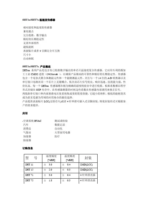
SHT1x/SHT7x温湿度传感器-相对湿度和温度的传感器-兼有露点-完全校准,数字输出-极好的长期稳定性-无需外部组件-超低能耗-表面贴片或者4引脚完全可互换-尺寸小-自动休眠SHT1x/SHT7x 产品概述SHTxx 系列产品是包含有已校准数字输出的单芯片温湿度复合传感器。
它应用专利的微加工工业CMOS进程(CMOSens®),以确保产品极高的可靠性和极好的长期稳定性。
传感器包含一个电容式聚合体测湿元件和一个能隙测温元件。
并且与一个14位的A/D转换器以及串行接口电路在同一个芯片上无隙耦合。
依次该芯片信号优良、响应迅速、抗扰能力强、性价比高。
每一个SHTxx 传感器都在极为精确的湿度校验室中进行校准。
校准系数都以程序形式存储在OTP内存中。
在传感器测量的时候这些系数在传感器内部调用来修正信号。
两线制串行接口和内部基准电压使系统集成变的简易快捷。
它超小的体积、极低的能耗使其成为甚至是最为苛刻的应用场合的最佳选择。
产品提供表面贴片LCC(无铅芯片)或者4针单排可插入式引脚封装。
特使封装形式可根据客户的需求提供。
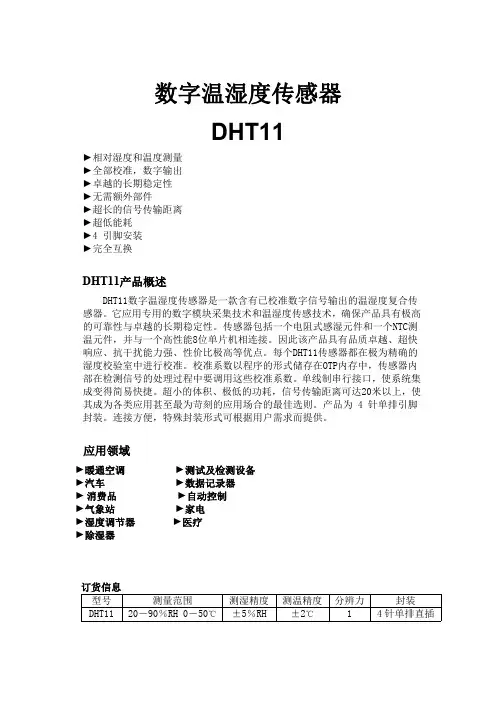
应用-空调系统HV AC -测试或检验-汽车-数据记录-消费品-自动化-气象站-大型家用电器-加湿器-医疗-除湿器订购信息型号湿度精度[%RH] 温度精度[%RH]封装SHT 11 ± 3.0 ±0.4 SMD(LCC) SHT 15 ± 2.0±0.3 SMD(LCC) SHT 71 ± 3.0 ±0.4 4针单排直插SHT 75 ± 1.8 ±0.3 4针单排直插1 传感器性能说明参数条件最小典型值最大单位湿度分辨率0.5 0.03 0.03 %RH8 12 12 bit重复性± 0.1%RH线性化见图一精度不确定性互换性完全可互换非线性度原始数据± 3%RH线性化<<1 %RH范围0 100 %RH响应时间1/e(63%)4 S缓慢流动的空气迟滞± 1%RH长期稳定性典型值<0.5 %RH/yr温度分辨率0.04 0.01 0.01 ℃0.07 0.02 0.02 °F12 14 14 bit重复性± 0.1℃± 0.2°F精确度见图一范围-40 123.8 ℃-40 254.9 °F响应时间1/e(63%) 5 30 S表1 传感器性能说明2 接口说明2.1 电源引脚SHTxx的供电电压在2.4 - 5.5V.上电后,传感器需要11ms月过期“休眠”状态。
温湿度传感器(型号:WHT20B)使用说明书版本号:1.0实施日期:2023-02-01郑州炜盛电子科技有限公司Zhengzhou Winsen Electronic Technology Co.,Ltd声明本说明书版权属郑州炜盛电子科技有限公司(以下称本公司)所有,未经书面许可,本说明书任何部分不得复制、翻译、存储于数据库或检索系统内,也不可以电子、翻拍、录音等任何手段进行传播。
感谢您使用本公司的系列产品。
为使您更好地使用本公司产品,减少因使用不当造成的产品故障,使用前请务必仔细阅读本说明书并按照所建议的使用方法进行使用。
如果您没有依照本说明书使用或擅自去除、拆解、更换传感器内部组件,本公司不承担由此造成的任何损失。
您所购买产品的颜色、款式及尺寸以实物为准。
本公司秉承科技进步的理念,不断致力于产品改进和技术创新。
因此,本公司保留任何产品改进而不预先通知的权力。
使用本说明书时,请确认其属于有效版本。
同时,本公司鼓励使用者根据其使用情况,探讨本产品更优化的使用方法。
请妥善保管本说明书,以便在您日后需要时能及时查阅并获得帮助。
郑州炜盛电子科技有限公司WHT20B温湿度传感器产品描述WHT20B温湿度传感器嵌入了适于回流焊的双列扁平无引脚SMD封装,温度和湿度信号可以在不同的引脚读出,底面3.0×3.0mm,高度1.0mm。
传感器输出经过标定的数字信号,标准I2C格式。
WHT20B温湿度传感器,包含一个全新设计的ASIC专用芯片内置晶体管Vbe温度特性,实现高精度温度检测;同时包含一个电容湿度芯片,其中湿敏材料吸湿后介电常数变化实现环境湿度检测。
并结合最新的集成电路信号处理技术而成的双芯片解决方案。
具有体积小、功耗低、可靠性高、兼容性好等优点。
产品特点⏹高精度,±3.0%RH和±0.5℃⏹宽电源电压范围,从2.0V到5.5V⏹采用SMD封装,适于回流焊⏹响应迅速、抗干扰能力强⏹高湿条件下优异的长期稳定性应用场景家电领域:家电、湿度调节、暖通空调、除湿机、智能恒温器、房间监视器;工业领域:汽车、测试及检测设备、自动控制;其他领域:数据记录器、气象站、医疗及其他相关温湿度检测控制。
智能温湿度监控系统在现代社会的众多领域中,温湿度的精确控制和实时监控变得越来越重要。
无论是在工业生产、农业种植、仓储物流,还是在医疗保健、科研实验室等环境中,合适的温湿度条件都是保证产品质量、设备正常运行、实验结果准确以及人员舒适和健康的关键因素。
为了满足这些需求,智能温湿度监控系统应运而生,它以其高效、精确和便捷的特点,为我们的生产和生活带来了巨大的改变。
智能温湿度监控系统是一种集成了传感器技术、数据采集与处理、通信技术以及智能控制算法的综合性系统。
它的核心组成部分包括温湿度传感器、数据采集器、通信模块和监控软件。
温湿度传感器是整个系统的感知器官,它们能够精确地测量环境中的温度和湿度值。
这些传感器通常采用先进的物理或化学原理,例如热敏电阻、热电偶、电容式湿度传感器等,以确保测量的准确性和稳定性。
为了适应不同的应用场景,传感器的形态和安装方式也多种多样,有的可以直接安装在墙壁或天花板上,有的则可以嵌入到设备内部进行测量。
数据采集器负责将传感器测量到的温湿度数据收集起来,并进行初步的处理和转换。
它通常具有强大的数据处理能力,能够对大量的测量数据进行快速的筛选、整合和存储。
同时,数据采集器还具备一定的智能判断功能,当测量数据超出预设的范围时,它可以立即发出警报信号。
通信模块则是实现数据传输的关键部分。
它可以通过有线网络(如以太网)或无线网络(如 WiFi、蓝牙、GPRS 等)将采集到的数据传输到监控中心或远程服务器上。
这样,用户无论身处何地,只要能够连接到网络,就可以实时获取温湿度数据,并对系统进行远程监控和管理。
监控软件是智能温湿度监控系统的大脑,它为用户提供了一个直观、便捷的操作界面。
通过监控软件,用户可以实时查看温湿度数据的变化趋势,设置报警阈值,生成数据报表,以及对系统进行参数配置和控制。
同时,监控软件还具备数据分析和挖掘功能,能够帮助用户发现潜在的问题和规律,为优化生产流程、提高管理效率提供有力的支持。
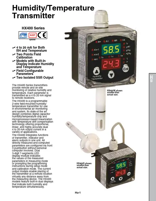
Humidity/Temperature TransmitterHu-1U 4 to 20 mA for Both RH and Temperature U T wo Points Field Calibration U M odels with Built-InDisplay Indicate Humidity and Temperature UF ield Configurable Parameters U Two Isolated SSR OutputHX400 SeriesThe HX400 Series transmitters provide remote and on‑sitemonitoring of relative humidity and temperature. Each parameter is transmitted as a 4 to 20 mA signal to remote receivers.The HX400 is a programmable 2‑wire field‑mounted humidity/temperature transmitter for use in environmental air monitoring and system. Its state‑of the art design combines digital capacitor humidity/temperature chip andmicroprocessor‑based linearization with temperature drift compensation technology offering proportional, linear, and highly accurate dual 4 to 20 mA output current in a variety of applications.The HX400 integrates functions of transmitter, indicator and alarm outputs in one unit. All directly measured and computed parameters are configured via front 3 pushbutton without personal computer involved. Dual 3‑digit 7‑segments LED display module indicates the values of the measured parameters in measuring mode or prompting the programming instructions during setup mode and calibration mode. The current output models enable placing of the transmitter at a remote location virtually any distance away from the measuring device. The HX400 models feature built‑in dual displays that indicate both humidity andtemperature simultaneously.HX402W shown smaller than actual size.HX402D shown smaller thanactual size.Hu-2SpecificationsLoop Power: 12 to 32 Vdc; dual 4 to 20 mA loop current; reverse polarity protected (Vloop = 24 Vdc, Tamb = 23 ±2°C, Rload = 250 Ω)Dual Isolated Solid State Relay Output: For output #1 and output #2; 15 mA maximum, 40 Vdc maximumAccuracy and Range of Output Current: ±0.02 mA; 4 to 20 mA (both channels)Accuracy @ 23°C and Scaleable Measurement Range: Without field calibrationRelative Humidity (RH): ±2%; 0 to 100%Temperature: ±0.5°C (0.9ºF)Dew Point: ±2°C (3.6ºF)Wet Bulb Temperature: ±2°C (3.6ºF), ‑20 to 80°C (‑4 to 176ºF)Repeatability of Relative Humidity and Temperature: ±1% RH, ±0.1°C Display Resolution: 0.1% RH, 0.1°C (temperature < 100°C)Response: 10 seconds (relative humidity); 30 seconds maximum (temperature)Filtering Ability of Sensor Cap: Stainless steel wire mesh; 0.05 mm Type of Fluid: Air and neutral gases Configuration Operation:Front 3 pushbutton with dual high bright 3‑digit LED moduleWorking Temperature:Electronics Device: ‑20 to 70°C (‑4 to 158ºF)Sensing Probe: ‑40 to 100°C (‑40 to 212ºF)Dual Miniature Loop-PoweredIndicators: Dual 3‑digits LED (green for humidity; red for temperature)Reading Rate: 1 update per secondDisplay AccuracyRelative Humidity: ±2% RH Temperature: ±0.5°C (1°F)Display Resolution:Relative Humidity: 0.1% RH Temperature: 0.1°C (0.2°F)Housing Material: POM(sensing probe); polycarbonate (electronics device)Protection: NEMA 4 (IP65) (electronic device); IP40 (sensing probe)Dimensions: 110 W x 80 L x 56 mm D (4.3 x 3.2 x 2.2")Weight: 250 g (8.8 oz)Probe Dimensions:Wall Mount Unit: L = 73 mm (2.87"), D = 15.5 mm (0.61")Remote Mount Unit: L = 100 mm (3.94"), D = 15.5 mm (0.61"), 100 cm (39.4") cable, 5.3 (0.21") diameter cableDuct Mount Unit: L = 200 mm (7.87"), D = 15.5 mm (0.61")RHCN-7000 U B right Green 3-Digit LED Display U 0 to 1 or 0 to 3 Vdc, 4 to 20 mA Inputs U 8 Amp Relay Output U S imple On/Off Control U C ompatible with RH Transmitters U O ptional RH ProbeRHCN-7001。
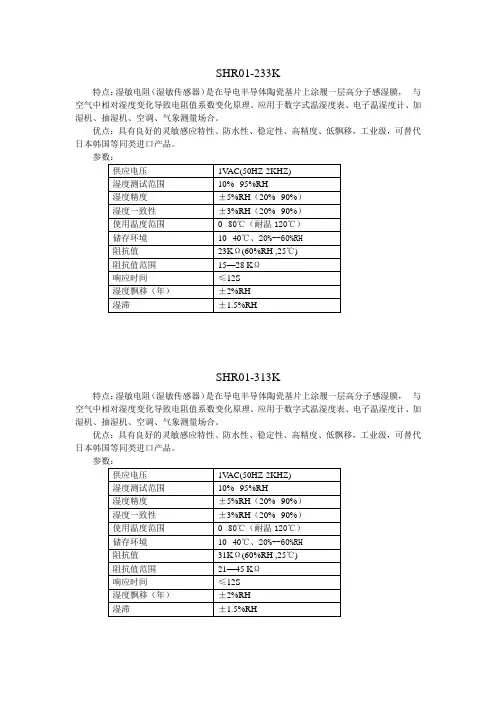
特点:湿敏电阻(湿敏传感器)是在导电半导体陶瓷基片上涂履一层高分子感湿膜,与空气中相对湿度变化导致电阻值系数变化原理。
应用于数字式温湿度表、电子温湿度计、加湿机、抽湿机、空调、气象测量场合。
优点:具有良好的灵敏感应特性、防水性、稳定性、高精度、低飘移,工业级,可替代日本韩国等同类进口产品。
SHR01-313K特点:湿敏电阻(湿敏传感器)是在导电半导体陶瓷基片上涂履一层高分子感湿膜,与空气中相对湿度变化导致电阻值系数变化原理。
应用于数字式温湿度表、电子温湿度计、加湿机、抽湿机、空调、气象测量场合。
优点:具有良好的灵敏感应特性、防水性、稳定性、高精度、低飘移,工业级,可替代日本韩国等同类进口产品。
特点:湿敏电阻(湿敏传感器)是在导电半导体陶瓷基片上涂履一层高分子感湿膜,与空气中相对湿度变化导致电阻值系数变化原理。
应用于数字式温湿度表、电子温湿度计、加湿机、抽湿机、空调、气象测量场合。
优点:具有良好的灵敏感应特性、防水性、稳定性、高精度、低飘移,高性价比,可替代日本神荣、北陆、韩国等同类进口产品。
SHR02-313K特点:湿敏电阻(湿敏传感器)是在导电半导体陶瓷基片上涂履一层高分子感湿膜,与空气中相对湿度变化导致电阻值系数变化原理。
应用于数字式温湿度表、电子温湿度计、加湿机、抽湿机、空调、气象测量场合。
优点:具有良好的灵敏感应特性、防水性、稳定性、高精度、低飘移,高性价比,可替代日本神荣、北陆、韩国进口等同类产品。
特点:湿敏电阻(湿敏传感器)是在导电半导体陶瓷基片上涂履一层高分子感湿膜,与空气中相对湿度变化导致电阻值系数变化原理。
应用于数字式温湿度表、电子温湿度计、加湿机、抽湿机、空调、气象测量场合。
优点:具有良好的灵敏感应特性、防水性、稳定性、高精度、低飘移,高性价比,可替代日本神荣、北陆、韩国进口等同类产品。
特点:电容式温湿度模块是将湿度传感器非线性电阻值转换为线性电压信号输出,体积小,使用方便,精度高。
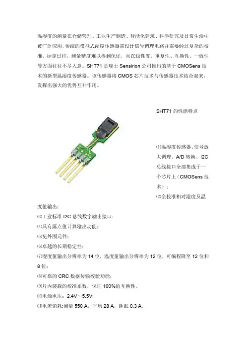
温湿度的测量在仓储管理、工业生产制造、智能化建筑、科学研究及日常生活中被广泛应用,传统的模拟式湿度传感器需设计信号调理电路并需要经过复杂的校准、标定过程,测量精度难以得到保证,且在线性度、重复性、互换性、一致性等方面往往不尽人意。
SHT71是瑞士Sensirion公司推出的基于CMOSens技术的新型温湿度传感器。
该传感器将CMOS芯片技术与传感器技术结合起来,发挥出强大的优势互补作用。
SHT71的性能特点⑴温湿度传感器、信号放大调理、A/D转换、I2C总线接口全部集成于一个芯片上(CMOSens技术);⑵全校准相对湿度及温度值输出;⑶工业标准I2C总线数字输出接口;⑷具有露点值计算输出功能;⑸免外围元件;⑹卓越的长期稳定性;⑺湿度值输出分辨率为14位,温度值输出分辨率为12位,可编程降至12位和8位;⑻可靠的CRC数据传输校验功能;⑼片内装载的校准系数,保证100%的互换性。
⑽电源电压:2.4V~5.5V;⑾电流消耗:测量550 A,平均28 A,睡眠0.3 A。
SHT71可通过I2C总线直接输出数字量温湿度值。
SHT71的封装形式为小体积4脚单线封装,其引脚说明如下:⑴SCK:串行时钟输入;⑵VDD:2.4~5.5V 电源端;⑶GND:接地端;⑷DATA:双向串行数据线。
SHT71工作原理内部结构及技术特点SHT71数字式温湿度传感器的内部结构框图如图1所示。
SHT71传感器是一款由多个传感器模块组成的单片全校准数字输出相对湿度和温度传感器,它采用了特有的工业化的CMOS技术,保证了极高的可靠性和卓越的长期稳定性,整个芯片包括校准的相对温度和湿度传感器,它们与一个14位的A/D转换器相连,此外还具有一个I2C总线串行接口电路,每一个传感器都是在极为精确的湿度室中进行校准的,校准系数预先存在传感器OTP内存中,在测量校准的全过程都要用到这些系数。
CMOSens技术的优势首先在于,利用具有不同保护下的"微型结构"检测电极系统与聚合物覆盖层组成了传感器芯片的电容,除保持电容式湿敏器件的原有特性外还可抵御来自外界的影响而对传感器进行保护,即使将传感器浸入到液体中也不会对传感器造成损害,同时还将温度传感器与湿度传感器结合在一起构成了一个单一的个体,这就可使测量精度提高并且可以精确得出露点值,而不会产生由于温度与湿度传感器之间随温度梯度变化而引起的误差。

温控器产品说明书WH1435+深圳市威尔海电子有限公司电话:0755-2953 9385 传真:*************技术支持:田工876传感器电源521锁定ON43负载+固态-WH1435系列简介:WH1435系列温控器的特点是高精度控制,内置优化过的PID 控制算法,调节非常简单,普通用户能轻松操作,控制精准。
无触点输出,1000W 内负载可以直接连接温控器. 系列型号: 型号 量程 调节步进 WH1435A -50℃~230℃ 1度 WH1435AF -58℉~230℉ 1度 WH1435B -9.9℃~99.9℃ 0.1度 WH1435C -30℃~300℃ 1度 WH1435CF -22℉~572℉ 1度 WH1435A+ -50℃~230℃/-58℉~230℉ 1度 WH1435C+ -30℃~300℃/-22℉~572℉ 1度①安装开口尺寸:②接线图:接线柱1和2 : 接固态继电器,1接正,2接负.接线柱3和4: 接负载,最大功率不能超过1000W 接线柱5和6: 接电源接线柱7和8: 接温度传感器.锁定开关: 将1或2拨到ON 的位置,可将已经设定好的控制参数锁定。
当负载大于1000W,需要接固态继电器控制。
指示灯状态说明:WORK指示灯为工作指示灯,长亮表示加热输出。
SET指示灯为设置指示灯,长亮表示在设置状态。
开启或关闭温控器:温控器通电后默认是开机状态。
在关机状态下按RST键一次可开启温控器,在开机状态下,按住RST键3秒以上,可关闭温控器。
◆设定控制温度:在待机状态下按SET键一次进入控制温度设置,按▲或▼键调整,按住▲或▼键三秒不放进入快速调整模式.再按SET键一次回到待机状态.设置控制参数:按住SET键三秒不放进入控制参数设置,按▲或▼键选择要调整的菜单,再按SET 键一次进入相应的控制参数设置状态,按▲或▼键调整需要修改的控制参数,调整好后按RST键退出,或系统延时5秒退出菜单代码说明:菜单代码详细说明 解释 单位D 输出控制参数P 输出控制参数DT 输出控制参数LS 设置下限 控制温度可设定的最小值℃HS 设置上限 控制温度可设定的最大值℃CA 温度较正 ℃AH 超高温报警 超高温报警 ℃AL 超低温报警 超低温报警 ℃D和P和DT这三个参数共同作用于控制输出,已经优化过PID算法,将三个参数大小作用于输出的方向一致,三个参数都是参数越小,输出功率越小,加温越慢,参数越大, 输出功率越大,加温越快.D是主要控制参数,主要调节在升温过程中减少输出功率的提前范围,参数越小, 提前减少输出功率的范围越大, 参数越大, 提前减少输出功率的范围越小P是主要控制参数, 主要调节在保温时的输出功率. 参数越小,功率越小, 参数越大, 功率越大.DT是辅助参数, 主要是动态调节输出功率.参数越小,调节幅度越小, 参数越大,调节幅度越大.D和P,DT的调节顺序, 先将DT设置为0. 当温控器恒温后调节P, 当P的参数调好后,再调节D,调整好后再将DT适当的加大.使系统的反应速度变快.◆温度校正功能:当测量温度与标准温度有偏差时,可使用温度校正功能,使机器的测量值与标准温度一致,校正后的温度=校正前的温度值+校正值(校正值可以为正数、负数和0)。
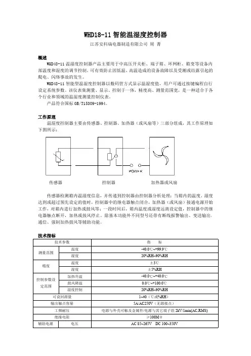
ZWDZ 系列智能温湿度监控器一、概述:本产品具有测量误差小、控制精度高、显示清晰明了、大方得体的优点,可广泛应用于各种需要高精度控温及控湿场合。
采用进口温度、湿度感应元器件的传感器对环境温度、湿度进行实时监控,数码管显示设置值和测量值。
根据预设控制值,自动或手动强制启动控制负载为调节环境的温度和湿度。
二、技术性能指标:1.工作电压:AC220V(可选AC/DC110~220V)50HZ±10%2.控温模式:升/降温型,控湿模式:除湿型3.工作环境:温度-10~55℃,湿度≤75%RHW,功耗:≤5W4.湿度测量范围:0~99%RH5.主控输出:有源/无源,阻性负载,触点容量AC220V 5A6.温度测量范围:-30~130℃(可选-50-120℃)7.报警输出:有/无源,阻性负载,触点容量AC220V 5A8.选配功能:RS485接口,二路4-20ma 模拟量三、面板布局示意图:四、接线示意图:五、操作流程对应“符号”说明:参数意义及出厂值:1.温度设置值“SE”(1~4路):可设置第一路(最多四路)温度控制目标值,当测量温度达到控制目标值时仪表启控,可作为升温型控制输出或降温型控制输出(升温或降温型下单时指定),设置范围为-50-120℃,升温型出厂设置默认为5℃,降温型出厂设置默认为35℃。
2.超温报警设置值“HE”(1~4路):可设置第一路(最多四路)温度超温报警目标值,当测量值大于超温报警目标值时仪表启控,设置范围为0-110℃,出厂设置默认为45℃。
3.低温报警设置值“LE”(1~4路):可设置第一路(最多四路)温度低温报警目标值,当测量值小于低温报警目标值时仪表启控,设置范围为-50-80℃,出厂设置默认为-20℃。
4.温度控制模式“CE”(1~4路):可设置第一路(最多四路)温度启控模式:设置为0:仪表为升温模式:设置为1:仪表为降温模式,仪表启控方式升温或降温模式在下单时指定。
智能温湿度监测管理机MJK2002使用说明书北京志翔领驭咨询有限公司监制第 1 页共1 页山西明佳电子技术有限公司生产目录一、产品说明.............................................................................. (3)二、产品结构及安装方式.............................................................................. (3)1、智能温湿度监测管理机外形2、安装方式三、技术参数.............................................................................. . (4)四、智能温湿度监测系统功能及连接方式 (5)五、智能温湿度监测管理机操作说明 (5)1 、参数设置功能2 、查询功能3 、背光灯六、智能温湿度监测管理机的显示及注意事项 (7)七、售后服务.............................................................................. . (8)一、产品说明二、产品结构及安装方式1 、智能温湿度监测管理机外形结构图一 图二(1)RJ45插座A 口:接管理计算机。
(2)RJ45插座B 口:接扩展分机或智能温湿度监控终端机。
(3)电源插座:DC12V 供电。
(4)信号接口:接AC220V 监测信号。
(5)USB 口:传感器接口,外接RHT-U120型智能外挂式温湿度传感器。
(6)指示灯(7)见图二:打开后盖,把SIM 卡放进卡槽 2 、产品的连接方法及安装方式本产品是通过网线来相互连接,其中RJ45(网络水晶头)的接法: B 类:橙白,橙,绿白,兰,兰白,绿,棕白,棕(注:本产品不能接入网络设备,如交换机、路由器等等) 壁持式金属挂板安装。
AB-WSK-HS(TH)精密型智能数显温湿度控制器传感器误差修正:温度-50℃~99℃显示方式:三位LED数码管显示,1位小数响应速度:典型值≤5S负载继电器输出容量:AC220V/7A(阻性负载时)二路有源输出体积:48*48*78mm※技术参数:供电电压:AC220V 50HZ测量控制范围:温度-50℃~99℃精度±1℃凝霜启控:88%RH+5%RH参数设置:上限值:温度-49-99℃下限值:温度-50-98℃有一路温度数显控制,一路湿度固定控制。
可对被测环境的温度、湿度进行实时精密监控。
使环境温度、湿度指标符合工作要求,并可以有效地防止凝露产生。
用数字显示温度(或订货时注明湿度)的设定值或测量值;用户通过按钮自行设定温度控制值。
湿度(或温度)启控值出厂前固定设置,用户不能自行设置(如有特殊设置要求请在订货时注明)。
有加热升温型和风扇降温型供用户选择。
※安装方式:嵌入式安装:在安装面板上开45+0.5×45+0.5mm孔,用安装支架将控制器固定在面板上。
基座式安装:将8芯继电器座卡在35mm安装道轨上或用螺钉固定在安装板上。
DT-KS-1C温湿度控制器DTCH-11A(TH)智能型数显温湿度控制器DTCH-11B(TH)智能型数显温湿度控制器ES-G 温度控制器ES-G温度控制器EM-D温度控制器DTCH-11C(TH)智能型数显温湿度控制器EJR-50W,EJR-100W,EJR-150W,EJR-200W加热器DTCHE-11A(TH)智能型数显温湿度控制器DTCHE-11B(TH)智能型数显温湿度控制器DT-WSK-HS(TH)数显温湿度控制器EJR-50W,EJR-100W,EJR-150W,EJR-200W加热器DT-WSK-JS(TH)数显温湿度控制器智能型数字温湿度自动控制器系列使用数字显示方式,使用户对环境一目了然,可根据需要修改温湿度的设定值,RS485 数字通讯接口能实现远程监控;适用于无人值变电所、高压开关配电柜、机构操作箱、箱式变电站、中置柜和其他封闭式的电力设备箱体内部的自动防凝露、除湿、加热和排风。
摘要为了有效的控制“回潮天”给人们生活带来的经济损失以及身体上的危害,设计了一种基于ARM芯片和ZigBee的室内智能温、湿度监控系统。
系统的总体结构是以S5PV210为核心,设计了监控系统的硬件电路、温湿度采集模块、通信接口电路、Mesh型ZigBee无线网络模块等电路。
其中室内环境监控系统软件程序设计部分包括:搭建Linux系统开发环境、移植Boot Loader、Linux内核的特点及移植、构建系统文件、建立QT/Embedded开发环境、设置QT 界面及相关驱动程序的设计等部分。
设计中温湿度传感器DHT22的测量精度满足设计要求,因此将它作为温湿度数据采集元件。
采集到的数据通过通信接口电路发送数据到Mesh型ZigBee无线网络传输多节点温湿度数据。
室内环境监控中心软件部分通过对数据的存储和分析做出相对应的控制动作,使得室内空间始终处于恒温恒湿状态。
通过系统测试,结果表明,该系统运行稳定,数据采集和显示准确、可靠,系统的测试精度满足家居生活的要求。
关键词:ARM;ZigBee;室内环境监控系统ABSTRACTIn order to effectively control "return" to the economic consequences of the people's life and physical harm, designs an arm-based chips and ZigBee smart temperature and humidity monitoring system.The overall structure of the system is based on S5PV210 as the core, the design of the control system hardware circuit, temperature and humidity acquisition module, communication interface circuit, Mesh type ZigBee wireless network module circuit, etc.Part of indoor environment monitoring center software program design, to build a Linux system development environment, the characteristics and the Boot Loader, the Linux kernel to transplant, build the system files, set up QT/Embedded development environment, set up the QT interface and related to the design of driver, etc.In the design of the measuring accuracy of temperature and humidity sensor DHT22 meet the design requirements, so use it as a temperature and humidity data acquisition device.Collected data through serial interface communication circuit sends data to the Mesh type ZigBee wireless network node temperature and humidity data.Indoor environment monitoring center software part through analyzing the data storage and make the output of the corresponding action, make interior space has always been in a state of constant temperature and humidity.Through the system test, the results show that the system runs stably, data acquisition and display of accurate, reliable, test precision of the system meet the requirements of home life.Key words: arm; zigbee; indoor environment monitoringsystem目录1绪论11.1 课题的背景及意义 (1)1.2 设计的主要内容 (1)2 总体方案的设计 (3)2.1 设计思想 (3)2.2 设计方案 (3)2.3 方案的选择 (4)3硬件系统的设计 (5)3.1 系统总体结构框图 (5)3.2 硬件电路 (6)3.2.1 主芯片的介绍 (6)3.2.2 电源电路 (6)3.2.3 复位电路 (7)3.2.4 存储系统 (7)3.2.5 SD卡 (9)3.2.6 JTAG接口 (9)3.3 Zigbee模块 (10)3.3.1Zigbee无线网络的设计 (10)3.3.2 Zigbee模块参数 (10)3.3.3Zigbee模块的组网 (11)3.3.4Zigbee网络特性 (11)3.4 串口通信电路的设计 (12)3.4.1 RS-232C (12)3.4.2 MAX3232芯片 (12)3.5 温湿度采集模块 (13)3.5.1 DHT22概述 (13)3.5.2 DHT22的工作原理 (14)4软件设计 (16)4.1 搭建Linux系统开发环境 (16)4.2 移植Boot Loader (17)4.3 Linux2.6内核特点 (18)4.4 Linux内核的移植 (18)4.5 构建系统文件 (20)4.6建立QT/Embedded开发环境 (22)4.7 设置QT界面 (23)4.8 相关驱动程序的设计 (26)5系统调试运行 (29)5.1 系统说明 (29)5.2 系统运行结果 (30)5.3 设计总结 (34)总结与展望......................................... 错误!未定义书签。