Improving thermal and combustion efficiency of gas water heater
- 格式:pdf
- 大小:1.02 MB
- 文档页数:8
第32卷第3期 2017年6月新型炭材料NEW CARBON MATERIALS Vol. 32 No. 3 Jun. 2017文章编号:1007-8827(2017)03鄄0271-06一种低膨胀高刚性的炭纤维网络增强聚丙烯复合材料袁剑民\ 冯艳荣\ 吴振军2,王彦军\李丝雨\孙萍1(1.湖南大学材料科学与工程学院,湖南长沙410082;2.湖南大学化学化工学院,湖南长沙410082)摘要:利用酚醛树脂粘接短切炭纤维,炭化得到全炭型的稳固炭纤维网络增强体(C F N R ),真空浸胶后制得一种低膨胀、 高刚性的CFNR /聚丙烯(P P )复合材料。
利用扫描电镜和热机械分析仪对CFN R/PP 复合材料的微观结构和热机械性能进行 表征。
结果表明,在相同的载荷条件下,常规短切炭纤维(SCF) /P P 复合材料的形变是C F N R /P P 复合材料的2. 3倍。
相同 温度下,CFN R/PP 复合材料、SC F/PP 复合材料和P P 的储能模量和弯曲模量都依次下降。
在30 ■益和110益时,CFN R/PP 复 合材料的弯曲模量分别为SCF /P P 复合材料的1.8倍和2.5倍。
而且,CFN R/PP 复合材料具有较高的热尺寸稳定性,其平均 热膨胀系数(30 ~120益)是SCF /P P 复合材料的1/4。
可见,与松散的短切炭纤维网络增强结构相比,CFNR 在提高聚合物复 合材料的刚性和热尺寸稳定性方面更有效。
关键词:炭纤维网络增强体;热机械性能;刚性;模量;热膨胀系数 中图分类号:TQ342+.74 文献标识码:A收稿曰期:2017鄄02-10;修回曰期:2017-05-26基金项目:湖南省科技计划项目(2014FJ4018).通讯作者:袁剑民,博士,讲师.E-mail: pangyuan2916@A carbon fiber network/polypropylene composite with alow thermal expansion coefficient and high stiffnessYUAN Jian-min 1, FENG Yan-rong 1, WU Zhen-jun 2, WANG Yan-jun 1, LI Si-yu 1, SUN Ping 1Abstract : A carbon fiber network reinforcement (CFNR) was prepared by bonding short carbon fibers with phenol formaldehyde resin followed by carbonization. The CFNR was vacuum-impregnated with molten polypropylene (PP ) to produce a CFNR/PP composite with a low thermal expansion coefficient and high stiffness. The microstructure and thermal mechanical properties of the composite were characterized by scanning electron microscopy and thermal mechanical tests. Results show that CFNR is more effective in improving the stiffness and thermal dimensional stability of polymer matrix composites than short carbon fibers. The deformation rate of a conventional short carbon fiber (SCF)/PP composite is 2. 3 times higher than that of the C F N ^P P composite under the same load. The decreasing order of the storage and bend moduli is CFNR/PP > SCF/PP >PP. The bend moduli of the CFNR/PP composite at 30 and 110 益 are about 1.8 and 2.5 times that of the SCF/PP composite ,respectively. The average thermal expansion coefficient of the CFNR/PP composite between 30 to 120 益 is 25% of that of the SCF/PP composite.Key words : Carbon fiber network reinforcement ; Thermal mechanical property ; Stiffness ; Modulus ; Thermal expansion coefficient Foundation item : Science and Technology Planning Project of Hunan Province (2014FJ4018).Corresponding author : YUAN Jian-min ,Ph. D .,Lecturer. E-mail : pangyuan2916@ 126. com(1. College o f Material Science and Engineering , Hunan University , Changsha 410082, China ; 2. College o f Chemistry and Chemical Engineering,Hunan University , Changsha 410082, China)炭纤维具有高比强度和比模量,良好的导电、导热性能,而且密度低、耐磨性能优异,是制备许多高 性能工程材料不可或缺的原材料,尤其是在先进聚 合物基复合材料的研究和应用中,炭纤维的作用越 来越重要。

热导率英语The concept of thermal conductivity is fundamental in understanding how heat travels through various materials.It's a measure of a material's ability to conduct heat, andit's crucial in fields ranging from engineering to environmental science.In everyday life, we encounter materials with varying thermal conductivities. For instance, metals like copper and aluminum are known for their high thermal conductivity, making them ideal for cookware and heat exchangers.Contrarily, insulators such as wood and plastics have low thermal conductivity, which is why they are used in construction to maintain a comfortable indoor temperature by reducing heat transfer.Understanding thermal conductivity is not just about the numbers; it's about the impact on our environment and energy efficiency. By choosing materials with appropriate thermal properties, we can design more sustainable and energy-efficient buildings and appliances.Innovations in materials science are constantly pushing the boundaries of thermal conductivity. For example, researchers are developing nanomaterials with tunable thermal properties, which could revolutionize electronics cooling and thermal management systems.Education on thermal conductivity should start early, as it lays the groundwork for a deeper understanding of physics and engineering principles. It's a topic that bridges the gap between theoretical knowledge and practical applications in our daily lives.In conclusion, thermal conductivity is a vital parameter that affects our comfort, the efficiency of our technologies, and the sustainability of our environment. By appreciatingits significance, we can make more informed decisions in our professional and personal lives.。

本体热效率英语Thermodynamic efficiency, also known as thermal efficiency, is a measure of the performance of a heat engine or any other system that converts thermal energy into mechanical work. It is a crucial concept in the field of thermodynamics and has important implications for the design and operation of various types of power plants, engines, and other energy conversion systems.The concept of thermal efficiency is based on the fundamental laws of thermodynamics, which govern the conversion of energy from one form to another. The first law of thermodynamics states that energy can neither be created nor destroyed, but it can be transformed from one form to another. The second law of thermodynamics, on the other hand, states that heat cannot spontaneously flow from a colder object to a hotter object without the assistance of an external agent, such as a heat pump.The thermal efficiency of a heat engine is defined as the ratio of the useful work output to the total heat input. In other words, it represents the fraction of the total energy input that is converted into useful work. The formula for calculating thermal efficiency is given by:Thermal Efficiency = (Work Output) / (Heat Input)The maximum theoretical thermal efficiency of a heat engine is determined by the Carnot cycle, which is an idealized thermodynamic cycle that represents the most efficient way to convert heat into work. The Carnot efficiency is given by the formula:Carnot Efficiency = 1 - (Tcold / Thot)where Tcold is the temperature of the cold reservoir and Thot is the temperature of the hot reservoir.The Carnot efficiency represents the upper limit of the thermal efficiency that can be achieved by any heat engine operating between the same two temperatures. In practice, however, real-world heat engines are subject to various losses and inefficiencies, such as friction, heat transfer limitations, and irreversible processes, which reduce their actual thermal efficiency compared to the Carnot efficiency.One of the key factors that affects the thermal efficiency of a heat engine is the temperature difference between the hot and cold reservoirs. The larger the temperature difference, the higher the potential for the engine to convert heat into useful work. This is whymany power plants, such as those that use fossil fuels or nuclear energy, strive to operate at the highest possible temperatures to maximize their thermal efficiency.Another important factor that affects thermal efficiency is the type of heat engine being used. Different types of heat engines, such as internal combustion engines, steam turbines, and gas turbines, have different design characteristics and operating principles, which result in varying levels of thermal efficiency. In general, more advanced and efficient heat engine designs, such as combined-cycle power plants, can achieve higher thermal efficiencies than simpler designs.The concept of thermal efficiency has important implications for the design and operation of various types of energy conversion systems, including power plants, transportation systems, and industrial processes. By understanding and optimizing the thermal efficiency of these systems, engineers and scientists can improve their overall energy efficiency, reduce fuel consumption, and minimize the environmental impact of energy production and use.In conclusion, thermal efficiency is a fundamental concept in thermodynamics that provides a measure of the performance of heat engines and other energy conversion systems. By understanding the factors that affect thermal efficiency and striving to maximize it, we can develop more efficient and sustainable energy technologies thatcan meet the growing demand for energy while minimizing the impact on the environment.。
工程塑料应用2019年,第47卷,第4期116[5] Jiang Jin,Liu Feixiang,Zhuang Kunyi,et al. Composites ofepoxy/graphene-modified-diamond filler show enhanced thermal conductivity and high electrical insulation[J]. Rsc Advances,2017,7(65):40 761–40 766.[6] 勾昱君,刘中良,张广孟,等.多壁碳纳米管长度对导热硅脂导热性能的影响[J].工程热物理学报,2014,35(6):1 185–1 188.Gou Yujun,Liu Zhongliang,Zhang Guangmeng,et al. Influences of multi-walled carbon nanotubes length on thermal properties of thermal grease[J]. Journal of Engineering Thermophysics,2014,35(6):1 185–1 188.[7] Qian Rong,Yu Jinhong,Wu Chao,et al. Alumina-coated graphenesheet hybrids for electrically insulating polymer composites with high thermal conductivity[J]. Rsc Advances,2013,3(38):17 373–17 379.[8] Lee H L,Kwon O H,Ha S M,et al. Thermal conductivityimprovement of surface-enhanced polyetherimide (PEI) composites using polyimide-coated h-BN particles[J]. Physical Chemistry Chemical Physics,2014,16(37):20 041–20 046.[9] Shen Xi,Wang Zhenyu,Wu Ying,et al. Multi-Layer grapheneenables higher efficiency in improving thermal conductivities of graphene/epoxy composites[J]. Nano Letters,2016,16(6):3 585–3 593.[10] Foygel M,Morris R D,Anez D,et al. Theoretical andcomputational studies of carbon nanotube composites and suspensions:Electrical and thermal conductivity[J]. Physical Review B,2005,71(10).DOI:10.1103/PhysRevB.71.104201. [11] 侯君.氮化硼/环氧树脂导热复合材料的制备与性能研究[D].天津:河北工业大学,2015.Hou Jun. Preparation and properties of thermally conductive boron nitride/epoxy composites[D]. Tianjin:Hebei University of Technology,2015.[12] Ahmad P,Khandaker M U,Amin Y M. Synthesis of boronnitride nanotubes by Argon supported Thermal Chemical Vapor Deposition[J]. Physica E:Low-dimensional Systems and Nanostructures,2015,67:33–37.[13] 徐昉,薛杰,李响,等. SiC–BN填料杂化柔性电绝缘高导热材料[J].高分子材料科学与工程,2018,34(9):156–159.Xu Fang,Xue Jie,Li Xiang,et al. SiC–BN hybrid highly elastic and electrical insulated thermal conductive material[J]. Polymer Materials Science & Engineering,2018,34(9):156–159.[14] Tabkhpaz M,Shajari S,Mahmoodi M,et al. Thermal conductivityof carbon nanotube and hexagonal boron nitride polymer composites[J]. Composites Part B,2016,100:19–30.[15] 董其伍,刘琳琳,刘敏珊.预测聚合物基复合材料热导率方法研究进展[J].材料工程,2009(3):78–81.Dong Qiwu,Liu Linlin,Liu Minshan. Advancement of the prediction methods of effective thermal conductivity of polymer-based composites[J]. Journal of Materials Engineering,2009(3):78–81.[16] Plast O H. Thermal conductive of composite materials[J]. RubberProcess,1981(1):9–11.[17] Every A G,Tzou Y,Hassehnam D P H. The effect of particle sizeon the thermal conductivity of ZnS/diamond composites[J]. Acta Metall Mater,1992,40(4):123–125.[18] Kaddouri W ,Moumen A E ,Kanit T ,et al. On the effect ofinclusion shape on effective thermal conductivity of heterogeneous materials[J]. Mechanics of Materials,2016,92:28–41.[19] 康志鹏.环氧树脂/碳化硅复合材料导热性能的多尺度模拟研究[D].太原:中北大学,2017.Kang Zhipeng. Multiscale modeling of thermal properities of silcon carbide and epoxy resin composites[J]. Taiyuan:North University of China,2017.[20] 孙颖颖,陈林,杜小泽,等.混合填充复合材料热导率方程的推导[J].化工学报,2015,66(S1):359–364.Sun Yingying,Chen Lin,Du Xiaoze,et al. Derivation of thermal conductive equation of hybrid filled composite[J]. Ciesc J,2015,66(S1):359–364.[21] 张晓光,盖鹏兴,张宝库,等. AlN/碳纤维混合填充橡胶复合材料的导热性能[J].科学通报,2018,63(23):2 403–2 410.Zhang Xiaoguang,Gai Pengxing,Zhang Baoku,et al. Thermal conductivity of rubber composite materials with a hybrid AlN/carbon fiber filler[J]. Chin Sci Bull,2018,63:2 403–2 410.Polyscope玻纤填充热塑性复合材料荣获JEC创新大奖Polyscope Polymers B.V.公司最近获得了JEC创新大奖汽车应用类别的奖项。

热能,动力工程节能技术英文文献Energy is essential for human life and the development of society. However, the excessive use of energy has resulted in environmental degradation and climate change. As a result, there is an urgent need for the development and implementation of energy-saving technologies, particularly in the field of thermal and power engineering.One of the key areas in which energy-saving technologies can make a significant impact is in the field of heat transfer. Heat transfer is the process of transferring thermal energy from one material to another. In thermal and power engineering, heat transfer is crucial for the efficient operation of machinery and equipment, such as boilers, heat exchangers, and refrigeration systems. By improving the efficiency of heat transfer processes, energy consumption can be reduced, leading to cost savings and environmental benefits.There are several energy-saving technologies that can be applied in the field of heat transfer. One such technology is the use of heat exchangers. Heat exchangers are devices that transfer heat between two or more fluids at different temperatures. By using heat exchangers, the energy that is generated during heating or cooling processes can be recoveredand reused, reducing energy waste and improving overall efficiency.Another energy-saving technology that can be applied in thermal and power engineering is the use of insulation materials. Insulation materials are used to reduce heat transfer between different materials, such as walls, pipes, and equipment. By insulating these materials, heat loss can be minimized, leading to energy savings and improved thermal efficiency.In addition to heat exchangers and insulation materials, there are other energy-saving technologies that can be applied in thermal and power engineering, such as energy-efficient heat pumps, cogeneration systems, and waste heat recovery systems. By integrating these technologies into existing thermal and power systems, energy consumption can be reduced, leading to cost savings and environmental benefits.Overall, energy-saving technologies play a crucial role in the field of thermal and power engineering. By implementing these technologies, energy consumption can be reduced, leading to cost savings and environmental benefits. As the global demand for energy continues to rise, the development and implementation of energy-saving technologies will be essential for a sustainable future.。

第43卷 第3期 包 装 工 程2022年2月PACKAGING ENGINEERING ·202·收稿日期:2021-06-08基金项目:国家自然科学基金(52005066);重庆市教委科技创新项目(KJCX2020032) 作者简介:杜柏林(1996—),男,重庆交通大学硕士生,主攻新能源汽车电池热管理。
通信作者:张甫仁(1975—),男,博士,重庆交通大学教授,主要研究方向为新能源汽车电池热管理。
CPCM/液冷复合电池热管理方式优化设计杜柏林,张甫仁,李世远,张林(重庆交通大学 机电与车辆工程学院)摘要:目的 为了解决锂电池组在放电倍率为2.5 C ,环境温度为308.15 K 下工作时,其最高温度、最大温差可能超过适宜温度的情况。
方法 建立基于复合相变材料(CPCM )/液冷复合的电池组散热模型,首先通过实验测得锂电池单体相关性能参数,然后利用数值模拟方法讨论CPCM 厚度对电池组散热性能的影响。
分析得出当CPCM 厚度在一定范围内变化时,单一的相变材料冷却方式不能将电池组最高温度控制在适宜的温度范围内,因此提出CPCM/液冷复合散热方式,以复合相变材料厚度、液冷通道间距、液体流速为设计变量,电池组最高温度和最大温差为优化目标进行多目标优化设计。
结果 结果表明,优化后的电池组最高温度和最大温差分别为316.88 K 和0.30 K ,满足设计要求,但相变材料在相变过程中存在泄露的风险。
结论 相较于单一的相变材料冷却方式,优化后的复合冷却模型能够大幅度降低电池组的最高温度,同时将最大温差控制在安全范围内;在保证散热模型最外层包装结构具有较高导热性的同时也要加强其结构设计,防止相变材料泄露。
关键词:锂电池组;电池热管理;复合相变材料;液冷;多目标优化中图分类号:U262.44;TM912.9 文献标识码:A 文章编号:1001-3563(2022)03-0202-08DOI :10.19554/ki.1001-3563.2022.03.025 Optimization Design of Thermal Management Mode of CPCM/ Liquid-CooledComposite BatteryDU Bo-lin , ZHANG Fu-ren , LI Shi-yuan , ZHANG Lin(School of Mechanotronics and Vehicle Engineering, Chongqing Jiaotong University)ABSTRACT: In order to solve the situation that the maximum temperature and maximum temperature difference of li-thium battery pack may exceed the suitable temperature range when it works at 2.5 C discharge rate and 308.15 K ambient temperature. The heat dissipation model of the battery pack based on composite phase change material (CPCM)/liquid-cooled composite is established. Firstly, the related performance parameters of the lithium battery were measured by experiments. Then, the influence of CPCM thickness on the heat dissipation performance of battery pack was discussed by numerical simulation method. The analysis shows that the maximum temperature of the battery pack could not be controlled within an appropriate range by a single phase change material cooling mode when the thickness of CPCM varied within a certain range. Therefore, CPCM/ liquid-cooled composite heat dissipation method was proposed, and the Multi-objective optimization design was carried out with the thickness of composite phase change material, liq-uid-cooled channel spacing and liquid flow rate as the design variables, and the maximum temperature and maximum temperature difference of the battery pack as the optimization objectives. The results show that, the maximum temperature. All Rights Reserved.第43卷第3期杜柏林等:CPCM/液冷复合电池热管理方式优化设计·203·and maximum temperature difference of the optimized battery pack are 316.88 K and 0.30 K respectively, which meet the design requirements, but there is a risk of leakage of the phase change material during the phase change process. Com-pared with the single phase change material cooling method, The optimized composite cooling model can significantly reduce the maximum temperature of the battery pack, while controlling the maximum temperature difference within a safe range. While ensuring high thermal conductivity of the outermost packaging structure of the heat dissipation model, the structural design should be strengthened to prevent the leakage of phase change materials.KEY WORDS: lithium battery pack; battery thermal management; composite phase change material; liquid cooling; multi-objective optimization为解决传统燃油汽车在工作过程中排放出大量的有害性气体的问题,实现可持续发展,许多国家都宣布了停止常规燃料汽车制造的截止日期并且建立了资金和政策来支持新能源汽车的发展[1]。
耐极端环境碳基复合材料主动热疏导设计与长寿命防护机理The design of actively thermally conductive carbon-based composites for extreme environments and their mechanismsfor long-term protection.Carbon-based composites have received significant attention due to their unique properties, such as high thermal conductivity, lightweight nature, and excellent mechanical strength. These materials are particularly suitable for applications in extreme environments where conventional materials may not suffice. The design of carbon-based composites with active thermal conductivity is crucial for dissipating heat efficiently and ensuring the long-term durability of these materials.One approach to achieving active thermal conductivity in carbon-based composites is through the incorporation of highly thermally conductive fillers, such as graphene or carbon nanotubes. These fillers can form efficient heat transfer pathways within the composite structure, enhancingthe overall thermal conductivity. Additionally, the alignment of these fillers along preferred directions can further enhance thermal transport properties.To ensure the long-term protection and durability of carbon-based composites in extreme environments, various mechanisms need to be considered. One crucial mechanism is the prevention of oxidation or degradation of carbonaceous materials at elevated temperatures. This can be achieved through the application of protective coatings that act as barriers against oxygen diffusion. Furthermore, the addition of antioxidants or sacrificial layers can provide additional protection against oxidative degradation.Another important factor to consider is resistance against mechanical loading and impact in extreme environments. Carbon-based composites often possess exceptional mechanical properties; however, they may still experience damage from heavy loads, intense vibrations, or harsh impacts. To mitigate this issue, reinforcement strategies such as fiber weaving or intercalation can be employed to enhance mechanical strength and toughness.In addition to protecting against oxidative degradation and mechanical damage, it is essential to address challenges related to thermal expansion mismatch between different components within a composite structure. Extreme temperature variations can induce significant stress on the material interfaces leading to delamination or cracking. To overcome this challenge, designing composite architectures with tailored interfacial properties or introducing compliant interlayers can effectively mitigate thermal expansion mismatch.In conclusion, the design of actively thermally conductive carbon-based composites for extreme environments requires considerations of multiple factors. These include incorporating highly thermally conductive fillers, preventing oxidation and degradation, enhancing mechanical strength, and addressing thermal expansion mismatch. By understanding and implementing these mechanisms, we can develop carbon-based composites that can withstand harsh conditions while maintaining excellent thermal conductivity and long-term durability.译文:耐极端环境碳基复合材料主动热疏导设计与长寿命防护机理碳基复合材料因其高热导率、超轻性和优异的力学强度等独特性质受到广泛关注。
装备环境工程第20卷第12期·78·EQUIPMENT ENVIRONMENTAL ENGINEERING2023年12月热空气作用下FM-2D橡胶材料老化本构模型研究陈杰1,李彪1*,唐庆云2,张腾3,李亚智1(1.西北工业大学 航空学院,西安 710072;2.工业与信息化部电子五所,广州 510000;3.空军工程大学 航空工程学院,西安 710038)摘要:目的建立热空气作用下氟醚-2D(FM-2D)橡胶材料的老化本构模型,形成老化作用下橡胶材料力学响应分析方法,为准确评估橡胶密封件使用寿命提供依据。
方法探究热空气作用下FM-2D橡胶材料老化机理,基于连续介质有限变形理论框架,采用热力学耗散势函数法,引入橡胶老化过程的势能函数,据此建立考虑橡胶材料老化的超弹性本构模型,基于橡胶老化试验,完成本构模型参数标定,实现老化作用下橡胶力学响应的预测。
结果建立了热空气作用下橡胶材料的老化本构模型,依据老化试验数据标定模型参数,分析了热空气作用下橡胶材料本构模型的可靠性。
结论建立的热空气作用下橡胶材料的老化本构模型可准确预测橡胶随老化时间演变的力学响应,有效模拟了橡胶材料的老化过程。
关键词:橡胶;超弹性;热空气;老化;力学响应;本构模型;应变张量中图分类号:TJ04 文献标识码:A 文章编号:1672-9242(2023)12-0078-07DOI:10.7643/ issn.1672-9242.2023.12.010Constitutive Modeling of FM-2D Rubber Materials Subject to Hot Air AgingCHEN Jie1, LI Biao1*, TANG Qing-yun2, ZHANG Teng3, LI Ya-zhi1(1. School of Aeronautics, Northwestern Polytechnical University, Xi'an 710072, China;2. Electronic Fifth Institute of the Ministry of Industry and Information Technology, Guangzhou 510000, China;3. School of Aeronautical Engineering, Air Force Engineering University, Xi’an 710038, China)ABSTRACT: This study aims to establish a constitutive model for rubber materials undergoing hot air aging, emphasizing the development of a mechanical response analysis method applicable for assessing the service life of rubber seals. Employing the finite deformation theory within the framework of continuous mechanics, the method incorporates the thermodynamic dissipa-tion potential function. The potential energy function representing the rubber aging process is introduced, leading to the formu-lation of a hyperelastic constitutive model that accounts for the effects of rubber material aging. To validate the model, rubber aging tests were conducted, and the model parameters were calibrated based on the experimental results. Application of the de-veloped constitutive model to FM-2D rubber material demonstrated its efficacy in accurately predicting the evolution of me-收稿日期:2023-11-15;修订日期:2023-12-12Received:2023-11-15;Revised:2023-12-12基金项目:国家自然科学基金(12072272);国家科技重大专项(J2019-I-0016-0015)Fund:National Natural Science Foundation of China (12072272); National Science and Technology Major Project (J2019-I-0016-0015)引文格式:陈杰, 李彪, 唐庆云, 等. 热空气作用下FM-2D橡胶材料老化本构模型研究[J]. 装备环境工程, 2023, 20(12): 78-84.CHEN Jie, LI Biao, TANG Qin-yun, et al. Constitutive Modeling of FM-2D Rubber Materials Subject to Hot Air Aging[J]. Equipment Environ-mental Engineering, 2023, 20(12): 78-84.*通信作者(Corresponding author)第20卷第12期陈杰,等:热空气作用下FM-2D橡胶材料老化本构模型研究·79·chanical responses under conditions of hot air aging. This model serves as a valuable tool for evaluating the durability of rubber seals and contributes to a more comprehensive understanding of the aging dynamics in rubber materials.KEY WORDS: rubber; hyperelasticity; hot air; aging;mechanical response; constitutive model; strain tensor橡胶密封件对保证发动机的性能、可靠性和安全性至关重要[1-2]。
热能工程专业英语Aadiabatic process -绝热过程aero engine -航空发动机afterburner -加力燃烧室air fuel ratio -空燃比air conditioning -空调aviation fuel -航空燃料Bboiling -沸腾Brayton cycle -布雷顿循环Ccapacity -功率,容量carburetor -化油器combustion -燃烧combustion chamber -燃烧室compressor -压气机condenser -冷凝器crank case -曲轴箱cylinder -气缸Ddiesel engine -柴油机diffuser -扩压器dry satured steam -干饱和蒸汽Eejector -喷射器engine -引擎enthalpy -焓entropy -熵evaporation -蒸发exhaust -废气Ffan -风机feed water -供水fundamental interval -基本间隔Ggas turbine -燃气轮机gas generator -燃气发生器generator -发电机guided missile -导弹Hheat -热heat pump -热泵Iimpeller -叶轮internal energy -内能intercooler -中间冷却器isothermal process -等温过程Jjet engine -喷气发动机KKelvin scale -开尔文刻度kinetic energy -动能Llatent heat -潜热Pphase -相piston -活塞power output -功率输出pressure -压强pressure ratio -压力比prime mover -原动机Sscavengine -扫气SFC=Specific Fuel Consumption -燃油消耗率stability -稳定性stator -定子stroke -冲程superheated steam -过热蒸汽Ttemperature -温度thermal capacity -热容量thermal efficiency -热效率thermal equilibrium -热平衡thermodynamics -热力学thermodynamic cycle -热力学循环thermometer -温度计thermometry -计温学turbofan -涡轮风扇发动机turboprop -涡轮螺桨发动机two-stage turbocharger -两级涡轮增压器Vvacuum -真空viscosity -粘性Wwaste-heat recovery -废热回收wet steam -湿蒸汽Nanjing University of Aeronautics and Astronautics -南京航空航天大学College of Energy & Power Engineering -能源与动力工程学院Thermal Energy and Dynamic Engineering -热能与动力工程Engineering Thermodynamics -工程热物理major =specialty -专业。
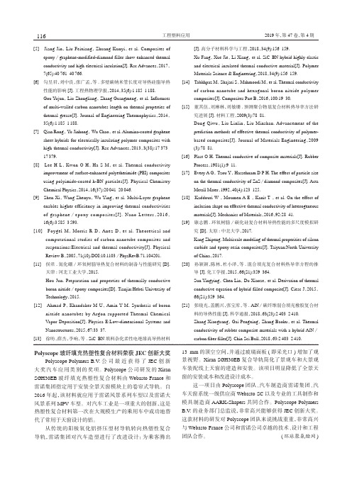
Extremely high thermal conductivity of graphene:Prospects for thermal management applications in nanoelectronic circuitsS.Ghosh,1I.Calizo,1D.Teweldebrhan,1E.P.Pokatilov,1,a͒D.L.Nika,1,a͒A.A.Balandin,1,b͒W.Bao,2F.Miao,2and u21Nano-Device Laboratory,Department of Electrical Engineering,University of California-Riverside,Riverside,California92521,USA2Department of Physics and Astronomy,University of California-Riverside,Riverside,California92521USA͑Received26February2008;accepted18March2008;published online16April2008͒The authors reported on investigation of the thermal conductivity of graphene suspended acrosstrenches in Si/SiO2wafer.The measurements were performed using a noncontact technique basedon micro-Raman spectroscopy.The amount of power dissipated in graphene and correspondingtemperature rise were determined from the spectral position and integrated intensity of graphene’sG mode.The extremely high thermal conductivity in the range ofϳ3080–5150W/m K andphonon mean free path ofϳ775nm near room temperature were extracted for a set of grapheneflakes.The obtained results suggest graphene’s applications as thermal management material infuture nanoelectronic circuits.©2008American Institute of Physics.͓DOI:10.1063/1.2907977͔As the electronic industry moves toward nanometer de-signs,one of the most important challenges is growing chippower consumption.Thus,thermal management in electroniccircuits is becoming an integral part of the design.1As theperformance of ultralarge scale integrated͑ULSI͒circuitsdepends on temperature T,even a small increase in T resultsin reduction of the device lifetime.A possible approachfor solving the thermal problem isfinding a material withextremely high thermal conductivity K,which can be inte-grated with Si complementary metal-oxide semiconductor ͑CMOS͒technology.Diamond and carbon nanotubes͑CNTs͒have been considered for such applications.2,3Although thesematerials have high thermal conductivity4–6they are not wellsuited for integration with CMOS.In this letter,we show that graphene,i.e.,individualsheets of sp2-hybridized carbon bound in two dimensions,7–9exhibits an extremely high thermal conductivity and longphonon mean free paths͑MFP͒.The letter provides details ofa measurement technique and explains the obtained K valueswith a simple model.A large number of graphene layers havebeen produced by the mechanical exfoliation of bulk highlyoriented pyrolitic graphite͑HOPG͒using the standardtechnique.7–10We used Si/SiO2substrates with an array oftrenches fabricated by the reactive ion etching͑RIE͒.Thenominal depth of the RIE trenches wasϳ300nm,while thetrench width D varied in the range of1–5m.Among the samples,we selected long grapheneflakes with a relatively constant width W suspended over the trenches and connected through the few-layer graphene regions to large graphitic pieces at the distance of few micrometers from the trench edges.The suspended single-layer graphene͑SLG͒flakes were found with the help of Raman spectroscopy.11–14The large graphitic pieces connected to SLG acted as heat sinks.None of the conventional techniques for measuring ther-mal conductivity of material worked well for the atomically thick graphene layers.For this reason,we developed an ap-proach on the basis of confocal micro-Raman spectroscopy. The schematic of the experiment and samples are shown in Fig.1.The laser light is focused in the middle of the sus-pended SLG with the spot size of aboutϳ1m.15A fraction of the excitation light͑=488nm͒is absorbed by graphene, which results in the heating power P G,while the remaining light is absorbed by the trench.Since K of the air is negligible,the heat generated in graphene laterally propagates through the layer with the thickness of a G =0.35Ϯ0.01nm toward the heat sinks on the sides of the flakes.Due to the small cross-sectional area of the heat con-ducting channel,even a small power dissipated in graphene can lead to a detectable rise of the local temperature.16 The suspended portion of graphene is essential for͑i͒forming a nearly plane heat wave front,which propagates to the heat sinks,͑ii͒reducing graphene—substrate coupling, and͑iii͒determining the fraction of power dissipated in SLG via the original procedure outlined below.The temperature rise⌬T G in the middle of the suspended portion of graphene can be established by measuring the shift in position of the graphene G peak⌬and using the peak temperature coeffi-cientG,which we reported earlier.16,17In this case,the micro-Raman spectrometer acts as a thermometer,which gives⌬T G=⌬/G.We induced substantial heating in thea͒On leave from:the Department of Theoretical Physics,Moldova State University,Chisinau,Republic of Moldova.b͒Author to whom correspondence should be addressed.Electronic mail: balandin@.URL:.FIG.1.͑Color online͒͑a͒High-resolution scanning electron microscopy image of the suspended grapheneflakes.͑b͒Schematic of the experimental setup for measuring the thermal conductivity of graphene.APPLIED PHYSICS LETTERS92,151911͑2008͒0003-6951/2008/92͑15͒/151911/3/$23.00©2008American Institute of Physics92,151911-1Downloaded 17 Apr 2008 to 169.235.12.206. Redistribution subject to AIP license or copyright; see /apl/copyright.jspmiddle of the suspended portion of the grapheneflake.Theaverage temperature rise along the length of the aboutflakewas aboutϳ70–100K.The heat transport in graphene layer in our experiment isat least partially diffusive.The latter is expected from thephonon MFP data reported for a rather similar material sys-tem such as suspended CNTs.5,6,18,19It was found that MFPin CNTs isϳ250–750nm at RT.18In our setup,the distancefrom the trench edge to the sink was in the range of6–10m.For the plane-wave heat front propagating in two opposite directions from the middle of SLG,we can writeK=͑L/2a G W͒͑⌬P G/⌬T G͒.Here,⌬T G is the change in the temperature in the suspended portion of grapheneflake dueto the change in the power⌬P G dissipated in graphene.Fi-nally,the thermal conductivity can be determined as K=͑L/2a G W͒G͑⌬/⌬P G͒−1.͑1͒It is not possible to directly measure⌬P G.The detector placed at the site of the sample measures P D=P G+P S,where P S is the power loss in Si trench.To determine P G,we de-veloped a calibration procedure with HOPG used for exfo-liation of graphene.The power absorbed in SLG can be writ-ten as P G=␣G a G͑1+R Si͒I0A,where A is the illuminated area, I0is the laser intensity on the surface,␣G is the absorption coefficient in graphene,and R Si is the reflection coefficient of Si.Here,we took into account the power,which is reflected from the Si trench and absorbed by the suspended portion of graphene.The reflection from SLG is assumed negligible, which is in line with thefindings of Ref.20.The integrated Raman intensity from SLG is given as21⌬I G=NG I0,where N is the number of the scattering atoms in the surface area A andG is the Raman scattering cross section.Now we can relate the integrated Raman intensity to the absorbed power as⌬I G=͑N/A͒͑G/␣G a G͒P G/͑1+R Si͒.Focusing the same laser beam on the calibration HOPG,we set P D=I0A.The integrated Raman scattered in-tensity from HOPG is obtained by summation over all n graphene layers,which make up HOPG,i.e.,⌬I HOPG =NH I0͚n=1ϱexp͑−2␣H a H n͒,where␣H is the absorption co-efficient and a H is the thickness of each monolayer.The later leads to⌬I HOPG=͑1/2͒͑N/A͒͑H/␣H a H͒P D͑1−R H͒,where R H is the reflection coefficient for HOPG.Defining the ratio of the integrated intensities as=⌬I G/⌬I HOPG,we express the power absorbed in graphene through the power measured by the detector asP G=͑/2͓͒H␣G a G/G␣H a H͔͑1+R Si͒͑1−R H͒P D.͑2͒Since the term in the square brackets is about unity,the mea-surement ofcompletes the calibration.Figure2shows measured G and HOPG for a typical suspended graphene and its“native”HOPG.The measured intensities define, which is almost constant over the examined⌬P D -ing the characteristic values of R H=0.27–0.34͑Ref.22͒and R Si=0.25–0.30for the rough Si trench together with the measured,we obtain that P GϷ͑0.11–0.12͒P D.Although the larger fraction of laser power is lost in the trench,it does not interfere with the measurement because the heat in Si trench diffuses to the substrate bottom and does not form a parallel conduction channel to the graphitic heat sinks.We independently confirm that substantial amount of power is dissipated in the trench by measuring the shift of Si 522cm−1peak with the laser excitation power.The tempera-ture coefficient,defined as⌬⌫͑T͒/T⌫͑T=0͒,for Si is well known and reported to be in the range ofϳ−4.7ϫ10−5͑Ref. 23͒−1–5.4ϫ10−5/°C.24From the measured shift of⌬ϳ1cm−1,we estimated that the temperature rise in Si trench is⌬Tϳ35K.The significant rise despite a large thermal conductivity of Si͑ϳ145W/m K at RT͒is in line with our assessment of the absorbed power distribution between the suspended graphene and the trench.To verify that there is no strong thermal coupling between graphene and SiO2layer, we determined the positions of W2and W3Si–O–Si stretch-ing bonds25,26in the range of800–1100cm−1at different power levels.The absence of shifts suggests that SiO2layer is not heated despite its low K͑ϳ1W/m K͒.Figure3shows a change in the G peak position with the total dissipated power P D for a typical suspended SLG.In thisfigure,the peak position change⌬is referenced to the value at the lowest excitation power.The extracted slope is ⌬/⌬P DϷ−1.226cm−1/mW.Knowing=⌬I G/⌬I HOPGfor FIG.2.͑Color online͒Integrated Raman intensity for the spectra region near G peak for suspended graphene and reference HOPG sample.The intensity ratio is approximately constant over the relevant excitation power range. Inset show the G peak region forgraphene.FIG.3.The shift in G peak spectral position vs change in total dissipated power.The slope of the dependence is used for the extraction of the thermal conductivity of graphene.Downloaded 17 Apr 2008 to 169.235.12.206. Redistribution subject to AIP license or copyright; see /apl/copyright.jspa given sample and power range,one can recalculate the measured slope into the value of⌬/⌬P ingG=−1.6ϫ10−2cm−1/K͑Ref.17͒and plugging into Eq.͑1͒the val-ues of a G,L,and⌬/⌬P G,we obtain,for the examined set of SLG samples,the averaged values in the range of K ϳ3080–5150W/m K.One should note that the upper bound of K for graphene is higher than the conventionally accepted values for individual CNTs.5,6The standard error in our measurement of⌬/⌬P D isϳ9%.From the Wiedemann–Franz law K e/=͑2/3͒͑k B/e͒2T ͑where K e is the electron contribution to K,=1/is the electrical conductivity,is the electrical resistivity,k B is the Boltzmann constant,and e is the charge of an electron͒and the measured resistance R=L/Sϳ1k⍀for the graphene conductor of the length L and cross-sectional area S,we estimated that the contribution of electrons to the thermal conductivity is less than1%at RT.This may seem unusual for a semimetal but in line with the predictions for graphite.27We evaluated the phonon MFP⌳in graphene from the expression K=͑1/2͒CV⌳,where C is the specific heat and V is the averaged phonon velocity.The coefficient 1/2appears due to the two-dimensional nature of -ing similarity of graphene and CNT material parameters and the data provided in Ref.18,we estimated from our K values that MFP in graphene is⌳ϳ775nm near RT.The Umklapp-limited phonon thermal conductivity can be approximated as K=V4/͑T␥2D͒,27,28whereis the mass density,␥is the Gruneisen parameter,andD is the Debye cutoff frequency.In order to get a rough estimate for K of graphene as compared to that of CNTs,K CNT,we neglect the difference inandD,and write:K/K CNT Ϸ͑V G/V CNT͒4͑␥CNT/␥G͒2.There is a discrepancy in reported values of␥for graphitic materials.At the same time,the published data suggest that␥for graphene is smaller than that in graphite or ing the values for graphene from Ref.29and CNTs from Ref.30,one gets͑␥CNT/␥G͒2Ϸ1.37.Thus,if one assumes equal phonon velocities in CNTs and graphene,the thermal conductivity of graphene should be larger than that in CNTs.For K CNT values reported in Refs.5and6we would get graphene’s low bound K estimate ofϳ4100–4800W/m K.It has been suggested that the in-plane Gruneisen parameter of graphite reduces with increasing temperature near RT.31The latter can be a possible reason for the higher maximum value obtained in our experi-ment because grapheneflakes experience substantial tem-perature rise.Based on the dispersion calculations in gra-phitic materials,32,33the phonon group velocity in graphene is higher than that in CNTs,which leads to larger K.An important implication of extremely high thermal con-ductivity of graphene is its possible use for thermal manage-ment in future ULSI circuits.While SLG is hard to produce, graphene multilayers are much cheaper and are expected to retain the heat conducting property.Graphene layers can be naturally attached to heat sinks,thus,avoiding the problem of thermal contact resistance,which is a major issue for CNTs.Theflat plane geometry of graphene simplifies its integration with Si CMOS circuits for thermal management.The work of A.A.B.group was supported by DARPA-SRC through the FCRP Center on Functional Engineered Nano Architectonics͑FENA͒.The work of C.N.L.and A.A.B.groups was supported,in part,by DARPA-DMEA through the UCR—UCLA—UCSB Center for Nanoscience Innovations for Defense͑CNID͒.A.A.B.acknowledges use-ful discussions with Dr.A.C.Ferrari,Dr.P.Kim,Dr.R. Lake,Dr.K.L.Wang,and Dr.D.G.Cahill.1A.Vassighi and M.Sachdev,Thermal and Power Management of Inte-grated Circuits͑Springer,New York,2006͒.2S.Jin and H.Mavoori,J.Electron.Mater.27,1148͑1998͒.3M.J.Biercuk,M.C.Llaguno,M.Radosavljevic,J.K.Hyun,and A.T. Johnson,Appl.Phys.Lett.80,2767͑2002͒;S.T.Huxtable,D.G.Cahill, S.Shenogin,L.Xue,R.Ozisik,P.Barone,rey,M.S.Strano,G. Siddons,M.Shim,and P.Keblinski,Nat.Mater.2,731͑2003͒.4A.V.Sukhadolou,E.V.Ivakin,V.G.Ralchenko,A.V.Khomich,A.V. Vlasov,and A.F.Popovich,Diamond Relat.Mater.14,589͑2005͒.5P.Kim,L.Shi,A.Majumdar,and P.L.McEuen,Phys.Rev.Lett.87, 215502͑2001͒.6E.Pop,D.Mann,Q.Wang,K.Goodson,and H.Dai,Nano Lett.6,96͑2006͒.7K.S.Novoselov,A.K.Geim,S.V.Morozov,D.Jiang,Y.Zhang,S.V. Dubonos,I.V.Grigorieva,and A.A.Firsov,Science306,666͑2004͒. 8Y.B.Zhang,Y.W.Tan,H.L.Stormer,and P.Kim,Nature͑London͒438, 201͑2005͒.9A.K.Geim and K.S.Novoselov,Nat.Mater.6,183͑2007͒.10F.Miao,S.Wijeratne,Y.Zhang,U.C.Coskun,W.Bao,and u, Science317,1530͑2007͒.11A.C.Ferrari,J.C.Meyer,V.Scardaci,C.Casiraghi,zzeri,F.Mauri, P.Piscanec,D.Jiang,K.S.Novoselov,S.Roth,and A.K.Geim,Phys. Rev.Lett.97,187401͑2006͒.12I.Calizo,F.Miao,W.Bao,u,and A.A.Balandin,Appl.Phys. Lett.91,071913͑2007͒.13I.Calizo,W.Bao,F.Miao,u,and A.A.Balandin,Appl.Phys. Lett.91,201904͑2007͒.14I.Calizo,D.Teweldebrhan,W.Bao,F.Miao,u,and A.A.Ba-landin,J.Phys.C͑unpublished͒.15M.Kuball,S.Rajasingam,A.Sarua,M.J.Uren,T.Martin,B.T.Hughes, K.P.Hilton,and R.S.Balmer,Appl.Phys.Lett.82,124͑2003͒.16A.A.Balandin,S.Ghosh,W.Bao,I.Calizo,D.Teweldebrhan,F.Miao, and u,Nano Lett.8,902͑2008͒.17I.Calizo,A.A.Balandin,W.Bao,F.Miao,and u,Nano Lett.7, 2645͑2007͒.18C.H.Yu,L.Shi,Z.Yao,D.Y.Li,and A.Majumdar,Nano Lett.5,1842͑2005͒.19H.Y.Chiu,V.V.Deshpande,H.W.C.Postma,u,C.Miko,L. Forro,and M.Bockrath,Phys.Rev.Lett.95,226101͑2005͒.20P.Blake,E.W.Hill,A.H.Castro Neto,K.S.Novoselov,D.Jiang,R. Yang,T.J.Booth,A.K.Geim,and E.W.Hill,Appl.Phys.Lett.91, 063124͑2007͒.21M.C.Tobin,Laser Raman Spectroscopy͑Wiley-Interscience,Toronto, 1971͒;M.M.Sushchinskii,Raman Spectra of Molecules and Crystals ͑Nauka,Moscow,1969͒.22A.Pfrang and Th.Schimmel,Surf.Interface Anal.36,184͑2004͒.23S.Perichon,V.Lysenko,B.Remaki,and D.J.Barbier,J.Appl.Phys.86, 4700͑1999͒.24R.Tsu and J.G.Hernandez,Appl.Phys.Lett.41,1016͑1982͒.25F.L.Galeener,Phys.Rev.B19,4292͑1979͒;A.E.Geissberger and F.L. Galeener,ibid.28,3266͑1983͒.26R.J.Hemley,H.K.Mao,P.M.Bell,and B.O.Mysen,Phys.Rev.Lett. 57,747͑1986͒.27P.G.Klemens and D.F.Pedraza,Carbon32,735͑1994͒.28R.Gaume,B.Viana,D.Vivien,J.-P.Roger,and D.Fournier,Appl.Phys. Lett.83,1355͑2003͒.29M.Hanfland,H.Besister,and K.Syassen,Phys.Rev.B39,12598͑1989͒. 30S.Reich,H.Jantoljak,and C.Thomsen,Phys.Rev.B61,13389͑2000͒. 31N.A.Abdulaev,R.A.Suleimanov,M.A.Aldzhanov,and L.N.Alieva, Phys.Solid State44,1859͑2002͒;N.A.Abdulaev,ibid.43,727͑2001͒. 32M.S.Dresselhaus and P.C.Eklund,Adv.Phys.49,705͑2000͒.33N.Mounet and N.Marzari,Phys.Rev.B71,205214͑2005͒.Downloaded 17 Apr 2008 to 169.235.12.206. Redistribution subject to AIP license or copyright; see /apl/copyright.jsp。
Improving thermal and combustion ef ficiency of gas water heaterS.Tajwar *,A.R.Saleemi,N.Ramzan,S.NaveedDepartment of Chemical Engineering,University of Engineering and Technology,G.T Road,Lahore 58290,Pakistana r t i c l e i n f oArticle history:Received 27July 2010Accepted 23December 2010Available online 11January 2011Keywords:Turbulence Recovery rate Draft Baf flea b s t r a c tThe traditional tank type water heaters have thermal and combustion ef ficiency of the order of 35%and 67.4%respectively.These ef ficiencies can be improved through various alterations.The factors,Turbu-lence,Temperature,Time (3Ts)have been identi fied to improve heat transfer.The water heaters combustion ef ficiency,thermal ef ficiency,recovery rate and draft were determined for a typical set of water heaters.The experimental investigation was carried out by introducing various types of baf fles in the flue pipe e.g.flat,conical,finned and barbed razor wire.It was observed that these design improvements resulted in the performance enhancement signi ficantly.The reason attributed to this achievement is increased retention time of flue gases,reduction in temperature of the exhaust gases and rapid turbulence in exhaust pipe.It is observed that barbed razor wire baf fle is the best amongst the options studied.The combustion and thermal ef ficiency in this case improved from 68%to 88%and 35%to 67.4%respectively.Ó2011Elsevier Ltd.All rights reserved.1.IntroductionNatural gas is one of the major fossil fuels in Pakistan.Almost half of the country ’s energy need is ful filled by it and its sectoral consumption pattern is shown in the Fig.1.Domestic share in total natural gas consumption is 24.1%and one third of it is being used in gas water heaters.Most of the water heaters being used in Pakistan are traditional tank type water heaters.The thermal ef ficiency and combustion ef ficiency has been reported as 35%and 67%respectively.The key factors that play important role in a water heater ’s ef ficiency are stack temperature,excess air and incomplete combustion.It is observed that flue gases in the gas water heaters leaves the stack at the temperature of 200 C.The discharge of flue gases at this high temperature results in the wastage of heat,and consequently larger amount of fuels are required.Lowering the flue gases temperature by 25 C reduces fuel consumption by 1%and improves the thermal ef ficiency by the same percentage [1].Excess air dilutes the combustion process as the composition of nitrogen is increased.Decreasing the excess air by 15%enhances the heating ef ficiency by 1%[2].The same observation is quoted by [3]that water heater ef ficiency is boosted upto 2.5%if the excess O 2level is decreased by 1%.Incomplete combustion occurs when (i)There is excessive or too little fuel available for combustion (ii)Air is not present in stoichiometricamount.(iii)Inadequate mixing of air and fuel for burning.Formation of each CO molecule generates 70%less heat as compared to the CO 2molecule [4].These factors need to be corrected for the improvement of thermal and combustion ef ficiencies of water heaters,so it can be done by improving:Time,Temperature and Turbulence (3Ts)[5].To increase heat transfer,a common method is to employ turbu-lence promoters of different geometry.Among these are using twisted tapes and wire coils [6],helical tape inserts [7],dimples [8]and ribs [9].Their experimental results con firmed that the use of extended surfaces leads to a higher heat transfer rate over the plain surfaces.However fins of different geometry can give much higher heat transfer values as compared to the above mentioned heat transfer enhancing elements [10].In addition to this it is found that the use of “barbed razor wire ”as heat transfer augmentation tool is not a very common practice.Typically in case of water heaters heat transfer is enhanced with improved convection.This effect is achieved by using baf fles [5,11e 13].Other contributor to high thermal and combustion ef fi-ciencies are:Enhanced pressure drop across turbulent flue gases which increase their contact time with water and reduce excess air levelsControlled draft flow due to restricted flow of flue gases can also improve fuel ef ficiencies apart from increasing thermal ef ficiencies [5,12]Baf fles help to direct flue gases in diverse direction [12,13]*Corresponding author.Tel.:þ924299029159;fax:þ924299250202.E-mail address:tajwar86@ (S.Tajwar).Contents lists available at ScienceDirectApplied Thermal Engineeringjournal ho mepage:www.elsevier.co m/locate/apthermeng1359-4311/$e see front matter Ó2011Elsevier Ltd.All rights reserved.doi:10.1016/j.applthermaleng.2010.12.038Applied Thermal Engineering 31(2011)1305e 13122.Theoretical backgroundGeometry and design of baf fle has major in fluence on the heating ef ficiency of the water heater.It has been reported that a baf fle designed with spikes on its external surface results in higher heat transfer ef ficiency as compared to the conventional flat plate type baf fle [11,14].Beckermann [15]reports that generally baf fling can enhance the heat transfer ef ficiencies up to 50%however it is limited to 82%where condensation may initiate [11].In case of flat plat type baf fle without any extended surfaces,heat transfer at molecular level is given asq b ¼Àk a ðv T =v y Þa ;y ¼0(1)where k a is the thermal conductivity of the flue gases,(v T /v y )a ,y ¼0is the temperature gradient at the flue gases side of the wall e gases interface and q b is the heat transfer rate per unit area of bare plate.When elements for heat transfer augmentation are placed on the surface to cover an area f A b ,the area for the heat transfer from the solid surface to the fluid decreases to (1Àf )A b ,where A b denotes the surface area of the bare plate.Hence,to estimate the heat transfer enhancement by augmentation elements,one may writeq a ¼q fr þq bp Àð1À4ÞK a ðv T =v y Þa ;y ¼0À4K s ðv T =v y Þs ;y ¼0(2)Where q a is the augmented heat flux,q fr is the heat flux at the interface between solid and fluid (flue gases),q bp is the heat flux through the base area of extended surface,k a and k s is the thermal conductivity of flue gases and solid material,respectively,and (v T /v y )a ,y ¼0and (v T /v y )s ,y ¼0are the temperature gradients at the interface between the free area and flue gases and between the base plate and base area of extended surfaces,respectively.3.Experimental details3.1.Description of equipments usedFlat plate,conical,finned and barbed razor have been used in this study to determine the effect of retention time of flue gases,exit gas temperature in relation with the turbulence created within the heating duct of the water heater (See Fig.2for picture plate and Fig.3for detailed engineering drawings).The baf fles tested were made of mild steel.Baf fle B is of uniform width and thickness throughout the entire length and baf fle C maintainsitsFig.1.Sector wise natural gas consumption inPakistan.s and IDs of baf fles tested.S.Tajwar et al./Applied Thermal Engineering 31(2011)1305e 13121306conical shape from its bottom to top.While baffle D and E are exactly of same dimensions with conical bottom to retainflue gases in stack pipe for longer time and is in cylindrical shape throughout the rest length.Only difference between D and E is in shape of the extended surface.Baffle D hasfins on it external surface that are5cm apart.Whereas baffle E has barbed razor wire welded along the entire length of the baffle except the conical section.The Water heater used for experimentation is the storage type water heater of capacity35gallons.The schematic diagram and picture plate of gas water heater is shown in Fig.43.2.Experimental procedureThe water heater isfilled to the desired level and natural gas burner is ignited at the bottom.Theflue gas rises through the duct located in the middle of the heater.Theflue gas after delivering the heat duty is released from the top where the temperature is recorded.When steady state is achieved the study is conducted with continuousflow of water and the measurements of gas compositions are conducted with the help of digitalflue gas analyzer(TESTO M/XL.Testo454).Typically water temperature at this stage is55 C.The baffles already indicated above wereinserted Fig.3.Engineering drawings and dimensions of baffles tested.S.Tajwar et al./Applied Thermal Engineering31(2011)1305e13121307in the water heater for each experimental work.Water and ambient temperatures were monitored.Volume of natural gas consumed and the time taken for each experimental run was also recorded.4.Results and discussionThe experimental results while using various designs of baf fles in the hot gas flow channel are presented in Table 1.It may be observed that the introduction of baf fle improved the Turbulence resulting in reduction in outlet gas Temperature and increased residence Time in comparison with the unbaf fled water heater.This is in line with the expected convective heat transfer phenomenagenerally established.In case of baf fle E the results have been more signi ficant.The thermal and combustion ef ficiencies,recovery rate and draft reduction in the above cases has been calculated and shown in the Figs.5e 74.1.Thermal ef ficiencyIn determining thermal ef ficiency gas consumed for heating the desired quantity of water is a key factor.Table 1shows that gas consumption is highest with unbaf fled water heater and least with baf fle E.This pattern of gas usage is responsible in making unbaf fled water heater ’s thermal ef ficiency at 35%,while baf fle E is 68%thermallyFig.3.(continued ).S.Tajwar et al./Applied Thermal Engineering 31(2011)1305e 13121308ef ficient.Fig.5exhibits comparison of thermal ef ficiency for each baf fle,calculated from Eq.(3)(see Annexure ).Apart from gas consumption,draft reduction;increase in turbulence and inside temperature contributed to make the water heater thermally ef fibustion ef ficiencyTurbulence of flue gases because of baf fle inclusion in stack pipe is solely responsible to make combustion process,ef ficient.Mixing of gases provides a chance to unburnt fuel and air to have intimate contact that leads to pursue the combustion reaction and conse-quently combustion ef ficiency is enhanced.Flue gases were examined with the help of digital flue gas analyzer that calculatedand displayed values of combustion ef ficiency using various built in functions (see Eq.(4)).Some other parameters of flue gases including unburned fuel like oxygen,carbon monoxide and hydrogen apart from combustion ef ficiency were also measured by the analyzer and is given in Table 2Process was most inef ficient in terms of combustion (67.4%)with no baf fle in stack pipe.However the ef ficiency rose to 77.3%,85.5%,88%,and 88.1%with the help of baf fle B,C,D and E respectively.4.3.Recovery rateRecovery rate indicates how quickly the water heater can heat cold water to the desired temperature.In this study recovery rateisFig.3.(continued ).S.Tajwar et al./Applied Thermal Engineering 31(2011)1305e 13121309a measure of quantity of water,the unit can heat up for a fixed time interval of 1h to a certain temperature of 55 C.The secret of obtaining larger volumes of water for the same span of time lies behind the greater rate of heat transfer.Recovery rate was recorded for each set of baf fle and calculations have shown that it rose from 20.6to 29gallons by using baf fle E in comparison to empty stack pipe.Results are shown in Fig.6.Fig.4.Plate picture of experimental rig (water heater).Table 1Observed parameters using various baf fles.Baf fle IDGas consumed (m 3)Timeduration (h)Flue gastemperaturefinally achieved ( C)Thermalef ficiency (%)A 1.13 2.0520035B 0.86 1.3815046C 0.78 1.2410052D 0.66 1.186560E0.591.106568Fig.5.Thermal and combustion ef ficiencies of water heater with designed test baf fles.Fig.6.Recovery rate of water heater with designed test baf fles.Fig.7.Reduction of draft by using designed test baf fles.S.Tajwar et al./Applied Thermal Engineering 31(2011)1305e 131213104.4.Draft reductionReduction in draft is one of the major reasons in enhancing the combustion and thermal efficiencies of water heaters.More heat transfer between hot medium(flue gases)and cold medium (water)took place as a result of reduction in draft.It indicates that reducing the draft shall increase heat transfer rate and the corre-sponding temperature offlue gases at exit is reduced.Draft is mainly dependant upon exit temperature offlue gases that was measured for each experimental run.It is evident from the Table1 that the gases leaving the unbaffled water heater were at200 C, conversely65 C temperature was measured for theflue gases leaving the water heater with baffle E in it.Calculations for draft were made using Eq.(5)and the results are given in Fig.7.5.ConclusionsThe thermal and combustion efficiencies of the tank water heater have been improved by improving the Turbulence of the combustion gases in theflow channel.This has been achieved by using various surface designs and it has been concluded that barbed razor wire gives the best combustion and thermal efficiencies.The improvement has been remarkable leading to the fuel saving of the order of40e50%.The introduction of the extended surfaces resulted in increase in the residence time of hot gases in theflow duct(Time), consequently reducing the Temperature offlue gases.The improved heat transfer has been achieved through effective Turbulence. AcknowledgementsAuthors are thankful to Sui Northern Gas pipelines Limited (SNGPL)and the Department of Chemical Engineering,U.E.T Lahore for providingfinancial assistance.AnnexureTheoretical calculationsFollowing parameters were calculated in order to compare the performance of baffles under study.1.Thermal efficiency:It is the most important parameter is the thermal efficiency of water heater.Thermal efficiency is the ratio of heat absorbed by water to the heat released by natural gas.It actually dictates that how well the heat released by fuel is consumed in heating up the water.The formula used for calculating thermal efficiency isThermal efficiency¼½mÂCpÂðT outÀT inÞ =VÂH v(3)bustion efficiency dictates that how efficiently heat is being extracted from the fuel.It is calculated by subtracting dryflue gas loss,unburnt fuel loss and latent heat loss from the whole fraction ie.100.The following formula is used by the digitalflue gas analyzer tofind out combustion efficiencyCombustion efficiency¼100ÀÂÂK grðFTÀATÞÃCO2þ½Xð2488þ2:1FTÀ4:2ATÞ =Q gr100þ½K1COÃCOþCO2ð4Þ3.Recovery rate is the quantity of water that can be heated uptoa certain temperature in1h by the water heater.In this study the recovery rate is taken as amount of water in gallons that can be heated up to55 C in1h.Recovery rate is calculated by following method,Recovery rate¼V w*60=t(5)4.Stack draft refers to the pressure difference that causes the movement offlue gases within the stack in upward direction.For efficient water heating,reduction in stack draft is very necessary so that theflue gases can remain in contact with water to be heated for longer time.D P¼ðPM=RÞ½1=T2À1=T1 gh(6) Nomenclaturem Mass of water,kg¼32kgCp Specific heat of water,J/Kg◦C¼4.184kJ/kg◦CT out Outlet water temperature,◦C¼55 CT in Inlet water temperature,◦CD T Change in temperature,◦C¼T outÀT inV Volume of gas consumed in heating up1batch of water,m3 H v heating value of natural gas KJ/m3¼3.4Â104kJ/m3Q gr gross calorific valueQ net net calorific valueCO%content of carbon monoxide influe gasCO2%content of carbon dioxide influe gasK1constant for natural gas(32)K gr%of carbon in fuel/Q grK net%of carbon in fuel/Q netFTflue gas temperatureAT ambient temperatureX MH2Oþ9HM H2OMoisture content of natural gasH Hydrogen content of natural gasV w volume of water used,m3t time required for heatingfixed volume of waterΔP Pressure difference,in H2OP atmospheric pressure,psiR ideal gas constant,psi ft3lbmolÀ1RÀ1T2temperature offlue gases,RT1Temperature of ambient air,Rg acceleration due to gravity,ft/s2h height of stack,ftk a thermal conductivity of theflue gases(v T/v y)a,y¼0temperature gradient at theflue gases side of the wall e gases interfaceq b heat transfer rate per unit area of bare plateq a augmented heatfluxq fr heatflux at the interface between solid andfluid(flue gases) q bp heatflux through the base area of extended surfacek s thermal conductivity of solid material(v T/v y)s,y¼0temperature gradients at the interface between the free area andflue gases and between the base plate andbase area of extended surfacesf coverage ratioTable2Flue gas analyzer results for each baffle.Variables Baffle A Baffle B Baffle C Baffle D Baffle EOxygen(%)16.8815.2213.0010.439.44CO(ppm)20203524CO2(%) 2.33 3.28 4.53 5.99 6.55NO(ppm)910141925NO2(ppm)0.6 3.80.8 1.8 2.8Flue temp.(◦C)172.8146.580.264.552.1NO x(ppm)1014152128H2(ppm)661157Eff G(%)67.477.385.588.088.1Device temp.(◦C)29.939.528.736.322.4S.Tajwar et al./Applied Thermal Engineering31(2011)1305e13121311References[1]Department of Energy(DOE),Office of Industrial Technologies,Energy Effi-ciency and Renewable Energy.Best Practices rmation on steam, (2001).[2] C.Galitsky,E.Worrell,Energy Efficiency Improvement and Cost Saving Oppor-tunities for the Vehicle Assembly Industry an ENERGY STAR Guide for Energy and Plant Managers LBNL-50939-Revision.Environmental energy Technologies Division Sponsored by the U.S.Environmental Protection Agency,March2008.[3]Canadian Industry Program for Energy Conservation(CIPEC).,Boilers andHeaters,Improving Energy Efficiency.Natural Resources Canada,Office of Energy Efficiency,2001a,(August).[4]Lecture notes on“Energy Conservation in Industry”by Professor Hebert M.Eck-erlin,North Carolina State /courses/mae406/ eckerlin/index.html.[5] C.Aguilar,D.J.White,L.David,Domestic Water Heating and Water HeaterEnergy Consumption in Canada Technical report by Canadian building energy end use,CBEEDAC2005e RP-02(April2005).[6] A.Dewan,P.Mahanta,K.S.Raju,P.S.Kumar,Review of passive heat transferaugmentation techniques,Journal of Power and Energy218(2004)509e527 Proceedings of the Institution of Mechanical Engineers,Part A.[7]S.Eiamsa-ard,P.Promvonge,Enhancement of heat transfer in a tube withregularly-spaced helical tape swirl generators,Solar Energy78(2005) 483e494.[8]J.Chan,H.Muller-Steinhagen,G.G.Duffy,Heat transfer enhancement indimpled tubes,Applied Thermal Engineering21(2001)535e547.[9]S.U.Onbasioglu,H.Onbasioglu,On enhancement of heat transfer with ribs,Applied Thermal Engineering24(2004)43e57.[10]N.Sahiti,F.Durst,A.Dewan,Heat transfer enhancement by pin elements,International Journal of Heat and Mass Transfer48(2005)4738e4747. [11]Technical Report,prepared for U.S.Department of Energy Office of Codesand Standards;“Technology Assessment And Screening Analysis AppendixB Supplement To The Water Heater Rulemaking Framework”;January1998.[12]Technical Manual,T.M.5-650,Central Boiler Plants.Publications of theHeadquarters,United States Army Corps of Engineers,13Oct1989.[13]S.J.Craig,J.F.McMahon,The effects of draft control on combustion,ISATransactions35(1996)345e349.[14]Guideline of Southern California Gas Company.,Gas Boilers.New BuildingsInstitute,November,1998.[15] C.Beckermann,V.W.Goldschmidt,Heat transfer in theflueway of waterheaters,ASHRAE Transactions92(2)(1986)485e495.S.Tajwar et al./Applied Thermal Engineering31(2011)1305e1312 1312。