罗兰写真机技术资料完整版
- 格式:docx
- 大小:24.64 KB
- 文档页数:7

上述的功能中有一些是选配项,而不是R OLAND 700 HiPrint 印刷机的标准配置。
用户可根据实际需要,在选配项价目表内进行自主配置。
ROLAND 700 HiPrint 印刷机正在不断研发中。
实践中获得的经验以及研究成果会转化为产品的设计。
因此,从保护您的利益出发,我们保留对设计和规格做出更改的权利。
只有订单中的书面确认才具有约束力。
本文件的内容,尤其是品牌名称、徽标和文字,都是曼罗兰平张印刷系统有限公司的财产,除非另有说明,都受到法律的保护。
未经曼罗兰平张印刷系统有限公司明确的书面授权,不得复制或使用本文件以及传播其内容给他人。
违者必究。
保留所有的权利,包括专利、实用新型或外观设计。
曼罗兰平张印刷系统有限公司· ROLAND 700 HiPrint 印刷机·中文· 05/2014设备基本机型1个上光机组包括加长收纸装置2个上光机组包括加长收纸装置可转换纸张翻转 双面印刷机长度/宽度/高度11个印刷机组(毫米) 11个印刷机组(英寸)18,756 x 3,612 x 2,140 738.5 x 142.2 x 84.2521,765 x 3,612 x 2,140 856.9 x 142.2 x 84.25– –18,756 x 3,612 x 2,140 738.4 x 142.2 x 84.2512个印刷机组(毫米) 12个印刷机组(英寸)19,936 x 3,612 x 2,140 784.9 x 142.2 x 84.25– –– –19,936 x 3,612 x 2,140 784.8 x 142.2 x 84.25最高印刷速度,张/小时(取决于所用的油墨、光油和承印材料)单面印刷模式16,000(选配17,200 *****) 最高可配置9个印刷机组****16,000(选配17,200*****) 最高可配置8个印刷机组****16,000 (选配17,200*****) 最高可配置7个印刷机组****16,000最高可配置9个印刷机组****双面印刷模式12,000 (选配13,200)12,000 (选配13,200)12,000 (选配13,200)12,000 (选配13,200)*在双面印刷模式**在单面印刷模式***取决于选配的套件****印刷机组越多速度越慢*****此选配项需要特殊说明= 标准配置 = 选配项 此表包含一系列重要的设备项目。
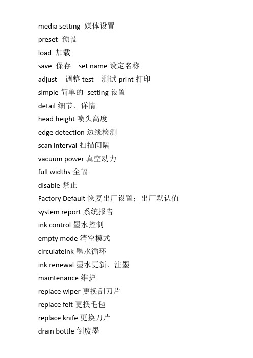
media setting 媒体设置preset 预设load 加载save 保存set name设定名称adjust 调整test 测试print打印simple简单的setting设置detail细节、详情head height喷头高度edge detection边缘检测scan interval扫描间隔vacuum power真空动力full widths全幅disable禁止Factory Default恢复出厂设置;出厂默认值system report系统报告ink control墨水控制empty mode清空模式circulateink墨水循环ink renewal墨水更新、注墨maintenance维护replace wiper更换刮刀片replace felt更换毛毡replace knife更换刀片drain bottle倒废墨system info系统信息model型号heater menu 加热菜单feed for dry 烘干进纸preheating预热sheet remain纸张剩余ink remaining剩余墨量print memo打印备忘录set length设置长度auto display 自动显示cutting menu切割菜单print-cut adj打印切割调试crop-cut adj裁切调整calibration校准function功能base point基点align point对齐点normalcl轻洗medium cl中洗powerful cl重洗sheet cut 切断纸张heater config 加热器配置print打印dryer 烘干cut config 切割配置force 刀压speed 速度offset补偿值up-speed加速。

写真机操作手册编辑:技术部面板主菜单说明:1. 装载打印载体(测量纸张大小)2. 切割(无用)3. 暂停(当机器打图时,喷头断线或其他问题时按此键暂停)4. 重新设置(当机器工作中想终止工作时按下此键)当按下“5馈送载体”键后,屏幕显示:馈送载体菜单:说明:此菜单是对载体进行装载操作,可选择“进”或“退”,按“退出”回到主菜单。
当按下“6 设置菜单”后,屏幕显示:设置菜单:说明:一般情况下C ,E ,F 项不能随便更改,建议保持默认数值不变。
当选择A 菜单时,屏幕显示:说明:各项设置如下:彩色模式(选“彩色”)优质模式(选“使用者自定”) 英寸点数(选“600”或“300”,建议选:“600”) 每行喷印次数(选 “六”次)托架速度(即小车的行走速度,选“7”或“8”次) 打印方向(选“双向”). 1 .当选择B 菜单时,屏幕显示:打印载体类型(选“卷轴或自动收卷”)打印载体标准(选“全部”)页边留白(选“正常”或“扩展”,建议选择“扩展”)自动装载延迟(选“6”)自动切割(选“关”)节省打印载体(选“开“)自动擦墨(选“开”或“关”)C 菜单用户勿须设定!!!当选择C当选择D 时,屏幕显示:说明:各项设置如下:选择使用者设定(把使用者选定的菜单设置保存在“1—8”中任意一项中)保存使用者设定(所需项选顶后必须保存在“使用者设定菜单”中选定的那一项中)计量单位选择(选“公制”)语种(选“中文”)初始设定值(勿动)打印设定值(勿动)液晶显示对比度(根据实际情况)当选择“7辅助功能菜单”时,屏幕显示:7辅助功能菜单说明:各项功能如下:清洗(用于清洗喷头出墨是否正常)存取墨水匣(打印过程中用于对喷头进行抽墨等操作)颜色校准菜单(用于喷头的校正)选择“颜色校准菜单“时,屏幕显示:颜色校准菜单青色垂直/水平(根据校准打印测试来定制)品红色垂直/水平(根据校准打印测试来定制)黄色垂直/水平(根据校准打印测试来定制)选择“校准菜单“时,屏幕显示:. 3 .选择“颜色静区菜单“时,屏幕显示:静区的数值(根据测试的值来定). 4 .喷头的校正一、喷头的校正分两步1. 颜色的静区校正,具体方法如下:主菜单里选择“辅助功能菜单”“校准菜单”“颜色静区菜单”“颜色静区测试”即在纸上打印出颜色静区测试条2. 颜色的水平垂直校正主菜单里选择“辅助功能菜单”“颜色校准菜单”“校准打印测试”即在纸上打印出颜色校准测试条,二、图纸纵轴线测试主菜单里选择“辅助功能菜单”“颜色校准菜单”“图纸纵轴线测试打印”即在纸上起始端开始走纸,默认参数为:83.82cm. 如果打完偏大或偏少此数值则用打印的实际数值代替原有的数值.注:默认参数83.82CM不会随更改数值所改变.. 5 .蒙泰软件安装及设置电脑设置:一在CMOS中对打印端口进行设置:重启电脑,在电脑进行硬件自检时按DEL键进入CMOS设置,进入INTEGRATED PERIPHERALS功能选项,将其中的Parallel Port Mode 设置为ECP(注意:一定要是标准ECP,而不能是EPP、SPP或者ECP/EPP),最后保存并建出BIOS设置,随后,电脑会重新启动,WINDOWS 系统自动检测到ECP打印口并为其安装驱动程序,这时,您就可以使用ECP打印口所提供的高速传输性能了。
DF-712U LED-UV Flatbed PrinterEngineer's manual0.Preparing0-1.Tools (1)0-2.Special tools (2)ponent introduce1-1.Sensor map (3)2.Function check2-1.Printer function check2-1-1.How to open service menu (5)2-1-2.Sensor check (5)2-1-3.Linear encoder check (6)2-1-4.Key check (6)2-1-5.I/S check (6)2-1-6.Limit position check (7)2-2.Flat bed function check2-2-1.Engineer mode of Touch panel (7)2-2-2.Engineer function (8)3.Adjustment3-1.Adjustment about printer3-1-1.Gap adjustment of head (10)3-1-2.Cap position adjustment (11)3-1-3.Cap height adjustment (12)3-1-4.Flushing adjustment (13)3-1-5.Belt position adjustment (15)3-1-6.Head BIAS adjustment (16)3-2.Adjustment about flat bed3-2-1.Parallelism adjustment of ta b le (18)3-2-2.Squarence ad ju st m ent (20)3-2-3.Feed belt tension ad j ust m ent (21)3-2-4.Table up/down belt tension ad j ust m ent (22)3-2-5.Print beginning position ad j ust m ent (23)4.Replacement4-1.Replacement about printer4-1-1.Cap top re p lacement (26)4-1-2.Damper replace m ent (28)4-1-3.Drain pump re p lacement (32)4-1-4.Head re p lacement (35)4-1-5.Carriage motor re p lacement (40)4-1-6.Feed motor re p lacement (44)4-2.Replacement about Flat bed4-2-1.Belt of feed re p lacement (56)4-2-2.Belt of table up/down replacement (57)4-2-3.Blowers replacement (58)0-1 、ToolsItem Name S pe c.1Screwdriver For 3.0mm phillips screws2Screwdriver For 3.0mm phillips screws3Screwdriver For 3.0mm phillips screws4Screwdriver For 2.3 mm phillips screws5Allen wrench 1.5~5mm a set6Allen wrench3mm T-type7C-Type buckle clamp For axis8Diagonal pliers9Needle Nose Pliers68 973 4 2 1 50-2 、Special ToolsItem Name S pe c.1Torque Wrenches Torque range 0.8~2.0Nm2Dial gage Graduation 0.01mm3Tension gage Maximum 3kgf4Parallelism jig4 1321-1 、Sensor MapHead limit sensorTable Up/Down limit sensorDis t ribu t orSingnal boardPrinter rear limit sensorPrinter front limit sensor UV lamp control board2-1 、Printer Function check2-1-1 、How to open Service menu4Then press the three cursor key and the power key at the sametime to turn on the power2-1-2 、Sensor checkTo ensure sensor on printerR : Rear paper sensorH : Head lock sensorO : Limit sensorw : Wipe home sensorb : Choke valve sensorC : Front cover sensor2-1-3 、Linear encoder checkTo ensure encoder stableThe carriage will move from home to limit position automatically2-1-4 、key checkTo check reaction of key pressedWhich button be pressed & shown on LCD2-1-5 、I/S checkTo ensure wipe & felt return back home positionWipeFront sideF el t2-1-6 、Limit position checkTo define the left side limit position of scan motorTo make sure power off and use the method below to turn onPress Enter bu tt onafter position f ixed2-2 、Flat bed function check2-2-1 、Engineer mode of Touch panelPress Dbe logo 5smenu2-2-2 、Engineer function2-2-2-1 、Page 1 of Engineer menuIt could show status of sensor & signal.& switchGo back front page Go to next page1 35 72 4 689 10 1 12 131.UV-FAN : Press this button for testing of UV fan.2.UV-LAP : Press this button for testing of UV lamp.(Don't stare UV lamp directly)3.PAUSE : Showing PAUSE button was pressed or not.4.T-END : Showing the signal of table end was correct or not.5.Start : Showing the start button was pressed or not.6.Media : Showing the signal of media sensor.7.Pause :Showing the pause button was pressed or not.8.UV :Showing the UV power switch was turned on or off.9.Up limit :Showing the status of up limit sensor.10.Down limit :Showing the status of down limit sensor.11.Front limit :Showing the status of front limit sensor.12.Rear limit :Showing the status of rear limit sensor.13.CR-ORG :Showing the status of printer head locked position.Three kinds of language could be choice To set value of UV lamp shot & shut2-2-2-2 、Page 3 of Engineer menu Ver. of TP & PLCSwitch of head protecting Switch of Media detecting3-1 、Adjustment about printer3-1-1 、Gap adjustment of headTo adjust the right height between head & tableLoosen the screws(6pcs) of the head holderDon't take off the screws , please justloosen them and make sure head holderis movable.Put the jig between the head & table and re-tight the screws to fix the head holder2kgT able3-1-2 、Cap position adjustmentTo make sure the position between head & cap.Alignment of position will avoid air leak from cap.st ancef rameAbout 32±1mmPlease fix the screws after everything be confirmed3-1-3 、Cap height adjustmentThe right height of cap could extend the life time of cap topLoosen the fixed screws firstTo adjust the two screws for heightat the sameJIGPutting jig between the cap & head like the photo shownThe jig dimension is 1.85mm3-1-4 、 Flushing adjustmentThe right flushing position could make longer life time of cap top and keep cleaning around the cap.To take off the Right under Cover firstThen open the SERVICE MENUUsing & key to move the head carriage andThe slot of carriage cap guide just touch backup cap base is the right positionThis adjustment is to prevent the belt wear which is caused by the belt contacting with the pulley Flanges excessively.To enter the service menu firstThe scan motor will continue to operate after press enter keyThe position is proper when thebelt is not touching the Flanges ofthe Drive Pulley excessively.When the position isimproper, make adjustment asfollows.Loosen the fixed screws whenadjustment is necessary.Fixed screwTo adjust depend on the method above.This is necessary to obtain the good printing quality. Be sure to operate thisalignment when the head is replaced.Enter to the BIAS test printand print test patternTest pattern is printed like shownLoosen the fixed screws(1/2 turn)To turn the Adjustment Screw to make thelines of each color in the test patternstraight.When the right half of the lines are shifting downwards, turn the screw CW.When the right half of the lines are shifting upwards, turn the screw CCW two or three round once to get back to the position where the right-side lines are lower than the left ones. Print the test pattern again, and perform the head adjustmentTorque for tightening is 2kgf • cm (20cNm).Make sure not to tighten the screws toostrong.3-2 、Adjustment about Flat bed3-2-1 、Parallelism adjustment of tableThis adjustment could get better printingTo install theCaged Ball LM Guide first.And fix the jig on the Caged Ball LMGuide.Then install the dial gage on the jigAdjustment point of TableAdjustment mechanism at each pointTo turn M10 screws CW & M6 screw CCW at the same time will move table upward.To turn M10 screws CCW & M6 screw CW at the same time will move table downward.M10screw nut3-2-2 、Squareness adjustmentAdjustment was necessary after change belt or re-combine printer and flat bed.Transparent film1 meter scale 1:1 square pattern printedon transparent film and fold it to checksquarenessIf tolence more than 0.5mm, to adjustgear of screw. Then print square patternand check again.3-2-3 、Feed belt tension adjustmentAdjustment was necessary after change belt.1 2Loosen the fixed screws and move the idler for belt tensionadjustment3-2-4 、Table up/down belt tension adjustmentAdjustment was necessary after change belt.To pull belt to touch the idler2 41 3Loosen the fixed screws and move the idler holder for belt tension adjustment13-2-5 、 Print beginning position adjustmentAdjusting beginning position to fit tableThe beginning position depend on front limit sensor. Pattern printed after adjustment and check the right position.1Loosen the fixed screw and move sensor for/backwardBeginning posi t ion3-2-6 、Table up/down limit position adjustmentAdjusting screw to effect height of sliderlimit positionGap 1.5mmSt opperThe gap is 1.5mm between stopper &slider3-2-7 、Table end position adjustmentSet the right value of table end could auto stop printing near rear limit position.To check the table end value and position after limit sensor replaced.To get into for/backward function page,first. Key-in 1200 in blank of beginning position.Then press the marked place on the touch panel 5s.Front limit sensor TableendpositionRear limitsensor4-1 、Replacement about prin t er4-1-1 、Cap top replacemen tRemove the tube from the drain pumpRemove the spring and don't lose it.Remove the Cap Top with pressing the[T] shape hook down-ward and pull upthe Cap Top.Fix the new Cap Top by fitting the [T]shape hook with the Cap Top Base.When you fix the Cap Top, fit theSpring in the Groove on the bottom ofthe Cap Top.When you fix the Cap Top, fit the Spring in the Groove on the bottom of the Cap Top. Connect the tubes of the Cap Top to the Pump. Both tubescan be connected to the both connectors shown in the figure.4-1-2 、Damper replacementClose the choke valve first, to avoidleak ink from head side.Disconnect all Head Ribbon Cables fromthe Head.Put the disconnected Head RibbonCables underneath the Carriage Board.Unhook the Head Cover from theHead.Pull up the Damper, the ink tubes and the Head Covers slowly with opening the Hook of the Head Cover.Do not touch the valve of the Damper. When you touch the valve, the ink leaks from the Damper. When the ink drops on the Head Board, the Head will be broken.Pick the both ends of the DamperJoint and remove it from the Damper.or left orientation.Check whether the Damper Joint cannot be removed by pulling up itCheck whether the Damper Joint cannot be removed by pulling up itFix the Damper, the ink tubes and the Head Cover set to the Head with opening the hook of the Head Cover. Press the Head Cover to the Head until the hook of the Head Cover clicks into placeConnect the Head Ribbon Cables. Do not connect the cables to the wrong connector or connect the cables halfway. The Head will be broken. Check whether the Head Ribbon Cablesare connected to the correct connectors. Open the Chock Valve. And perform『 Power CL. 』 or 『 CHOKE CL. 』 once.4-1-3 、Drain pump replacementRemove the motor cable from the connector.Remove the tubes of the Cap Top and the drain tube.Remove the two screws fixing the Pump Unit Stay and take out the Pump Unit.Remove the two screws shown in the figure and remove the Pump Unit Stay.Remove the three screws shown in the figure and remove the motor from the Pump.Fix the Pump Unit Stay to the Pump with the two screws shown in the figure.Fix the Pump Unit with the two screws shown in the figure.Connect the tubes of the Cap Top and the drain tube to the Pump Unit.Connect the motor cable to the connector.Select [SERVICE MENU]>[I/SMENU]>[PUMP CHECK], and perform [PUMPSUCTION] and [PUMP RELEASE] tocheck the pumps work correctly.Clear the pump times. Select [SERVICE MENU]>[HISTORY MENU]>[MOTORGROUP]>[PUMP TIMES]>[CLEAR], and press the [ENTER] key.4-1-4 、Head replacementDisconnect all Head Ribbon Cables from the Head. Put the disconnected HeadRibbon Cables underneath the Carriage Board.Unhook the Head Cover from the HeadPull up the Damper, the ink tubes and the Head Covers slowly with opening the Hook of the Head Cover.Do not touch the valve of the Damper. When you touch the valve, the ink leaks from the Damper. When the ink drops on the Head Board, the Head will be broken. To prevent the ink from leaking or spattering, put the cloth on the Right Under Cover.Remove the screws as shown in the figureand remove the HeadFix the Damper, the ink tubes and the Head Cover set to the new Head.Turn the head rank label to the left and fix the Head.Press the Head Cover to the Head until the hook of the Head Cover clicks into place. Be careful not to make the head surface touch with the Head Carriage Base.Connect the Head Ribbon Cables to the Head.Do not connect the cables to the wrong connector or connect the cables halfway. The Head will be broken.Check whether the Head Ribbon Cables are connected to the correct connectors.Fix the Head with the screws as shown in the figure. You do not have to care about the order for fixing the screws.Use the 6kgf·cm to tighten up the screws by torque driver and the hexagonal bit.Turn on the Main Power SW, and t hent urn on the Sub Power SW while pressing the left, right and down keys to enter the Service Mode.In [PRINT MENU]>[HEAD RANK] menu, input the Head Rank shown in the figure printed on the label on the carton box of the Head.Input the Head Rank by selecting the digit with the left andright keys and changing the parameters with the up and down keys.Press the [ENTER] key to save the settings.Perform [FUNCTION]>[CLEANING]>[POWERFUL CL.] once.Clear the Head information. Perform[SERVICE MODE]>[HISTORYMENU]>[HEAD GROUP]>[SHOT COUNT 1] to[SHOT COUNT 8]>[CLEAR].Perform the following adjustments.1. THERMISTER CHECK[SERVICE MENU]>[THERMISTOR CHK]2. Test PrintWhen the printing result has a banding, a missing dot, a scratchy printing, or a blurred printing, perform the cleaning again.3. [BIAS ADJUSTMENT]4. [BI. DIR. ADJUSTMENT]4-1-5 、Carriage motor replacementRemove the Panel Cover first.When removing the Panel Cover, removethe ribbon cable from the Panel Board.Disconnect the connector of the MotorCable.Remove the spring on the Flange. Remove the three screws fixing theFlange, and remove the motor together with the Flange.The fixing direction of one screw nearthe spring is different from the others.Remove the three screws shown in the figure to remove the motor from the Flange. And fix a new motor to the Flange.Be careful with the fixing direction of the Flange in relation to the motor cables.Tighten up the three screws to fix the Flange in the order shown in the figure.Connect the connector of the Motor CableMove the Head Carriage by hand to the lock positionFix Panel Cover.Perform the SERVO LOCK CHECK.After turning on the Main Power SW, turn on the Sub Power SW while pressing the left, right and down keys to enter the Service Mode.In [MOTOR MENU]>[SERVO LOCK] menu, select [S].Move the Head Carriage left and right by hand and makesure the value on the LCD changes depending on the head Position.Press the [ENTER] key to excite the motor.Check the Head Carriage can not be moved easily by hand and the value on the LCD doesn't change.Perform the AGING. Go back to the [MOTOR MENU], and select [AGING]>[SCAN] and press the [ENTER] key. Make sure the machine per-forms AGING and then, finish it by pressing [ENTER] key.Don't load any media on the table when Performing [AGING]Clear the motor working hours.Go back to the Service Menu, and select[HISTORY MENU] >[MOTOR GROUP]>[MOTOR HOURS S]>[CLEAR] andpress the [ENTER] key. The motorworking hours will be reset to 0.4-1-6 、Feed motor replacement※Please turn off the power of flat bed before feed motor replacement.It could avoid printer for/backward movement.Remove the Right Side Frame Stay.When removing the Panel Cover, removethe ribbon cable from the Panel Board.Remove the Grit Encoder Board.Remove the Grit Encoder Stopper.Remove the Grit Encoder.Make sure not to scratch or leave any fingerprints on the Grit Encoder.Move the Head Carriage leftwards by hand.Remove the Inner Cover.Remove the screw fixing the Cable Support and make it floated.Remove the Feed Motor Cable with the junction cable from the Junction Board.Remove the spring.Remove the three screws shown in the figure and remove the Feed Motor.The bottom screw shown in the figure is removed through the slit on the bottom of the BedPull out the Feed Motor leftward and takingout it from the rear side of the Cap Top unit.Remove the three screws as shown in the figure to remove the motor from the Flange. And fix a new motor to the Flange.Be careful with the fixing direction of the Flange in relation to the motor cables.Take in the new Feed Motor from the rear of the Cap Top unitand fit it with the Frame.。

罗兰700维修手册机械部分产品培训目录第一章技术数据第二章安装第三章输纸机第四章输纸定位第五章摆动叼纸牙第六章输纸滚筒第七章滚筒第八章传纸器第九章输墨装置第十章润版装置第十一章主传动第十二章收纸装置第十三章润滑——供气第十四章电子部件的信息第十五章上光机组第十六章APL / PPL装版系统1.1 概述1 输纸机2 输纸台3 摆动叼纸牙4 输纸定位滚筒5 压印滚筒6 传纸器7 橡皮滚筒8 印版滚筒9 供墨装置10 润湿装置11 收纸滚筒12 收纸装置1-51.2 规格尺寸,mm纸张(3B幅面)最大740×1040最小340×480图像区域 715×1020印品起点 10-12印刷材料厚度 0.04-0.1R702-R709 15000张/小时最大印刷速度R710 13000张/小时系列747以上的机型(参见第6页)标准印版滚筒印版滚筒直径(滚枕)300印版滚筒下陷0.5印版滚筒直径299印版边缘到印品起始点43印版厚度0.3-0.5印版(长度×宽度) 785×1030包衬纸 755×1030圆周方向套准调整,机动±1轴向方向套准调整,机动±1橡皮滚筒橡皮滚筒直径(滚枕)300橡皮滚筒下陷 2.6橡皮滚筒直径294.8橡皮布(长度×宽度),带夹条。
910×1060包衬纸770×1030面纸 780×1030橡皮布厚度 1.9压印滚筒:压印滚筒直径600滚枕的直径599.31-5选配基础 纸堆高度标准 mm 275 550 主纸堆 1180 1455 1730 输纸机(没有纸台)剩纸纸堆 500 500 500 主纸堆 1080 1355 1630 输纸机(没有纸台)中间纸堆100 100 100纸堆高度144选配基础 纸堆高度标准 kg 275 550 主纸堆 1300 1300 1300 输纸机(没有纸台)剩纸纸堆 450 450 450 主纸堆 1300 1300 1300 输纸机(没有纸台)中间纸堆280 280 280压缩空气供气 操作压力 标准 8巴APL/PPL 换版装置 9巴纸张翻转 10巴1-91-81.4 快速转换(选配项)概述德鲁巴2004展览会上展出了罗兰700的高端机型带有全面快速转换功能。

下面将罗兰FJ600/500/400/540/740系列写真机常见技术问题—一列举出来,并提供相应解决办法,希望能给喷友带来一点帮助。
一、打印图象中有明显断线条纹原因:墨头断针引起,压电式喷头只要有一个墨孔堵塞,就有可能造成在图象中产生断线条纹。
如有多个喷孔堵塞,将使断线条纹愈变严重。
解决方法:1、清洁墨头,把堵塞喷头清洁出来;2、管道中有杂;3、墨囊中有杂质,清洗墨囊管道;4、墨水被污染;5、墨水品质有问题,更换墨水;6、环境问题,温度太低,须安装空调,改善环境温度;7、喷头状态不佳,更换喷头;8、喷头表面太脏,有绒毛,清洁喷头表面;9、刮片、墨栈太脏,清洗刮片、墨囊、墨栈;10、墨囊中有空气管道,将墨囊中空气抽出。
二.打印图象中有叠印式深色条纹原因:1、墨头偏位,单墨头有斜向偏位,两墨头位置不齐。
2、送纸器夹纸太紧,造成进纸不畅,给Y轴步进电机造成较大阻力,不能达到标准步进值。
3、不同厚薄纸张进纸时步进量有差异。
解决方法:1、校准喷头,请联系专业技术人员处理。
2、采用手动放纸,减少阻力。
3、调整机器内纸张步进设置CALIBRATION菜单,增加或减少步进值。
4、喷头断线,清洗喷头。
5、打印墨量不够,加大出墨量。
6、放纸器太紧,放松放纸器。
三.打印过程中墨车在图象两端停顿数秒原因:1、电脑运算速度跟不上传输速度、打印速度。
2、采用打印口传输,大图时传输速度跟不上打印速度。
解决方法:1、更换速度更快的电脑,一般要求使用奔4 1.7G以上的电脑。
2、采用100M网线传输,网络传输速度比打印口传输速度快。
3. 机器死机将机器外壳接地4. 电脑死机重启电脑四.滴墨甩墨解决方法:1.温度太低,提升环境温度。
2.喷头未清洗干净,重新清洗喷头。
3.管道或墨囊破裂,更换管道或墨囊。
4.墨水加得太多,加墨水量不超墨盒。
五.墨头不出墨解决方法:1.墨囊中无墨水(墨合) ,抽墨或加墨水;2.喷头数据线未插好,重新插喷头数据线;3.喷头坏,更换喷头;4.喷头车控制板故障,更换喷车控制板。
罗兰写真机FJ 740K FJ 540K 品牌Roland类型大幅打印售后服务全国联保针式打印机特殊功能票证打印机最大打印幅面1859mm是否支持网络打印是是否支持自动双面打印否供纸方式自动接口类型以太网新奇特新鲜出炉适合的送礼人物类型事业型山东东方软图提供北京东方软图山东分公司联系人刘经理联系电话158****9202邮箱 您是否曾经觉得终日在为打印而等待这是因为您尚未拥有Roland公司精心打造的Hi-Fi JET PRO II颜料/染料型喷绘写真机。
Hi-Fi JET PRO II 的打印速度高达28米2/小时300英尺2/小时。
这绝不是草图模式这是Roland为标牌业、展览业和POP生产者特别创造的独特的标牌品质模式仅需14分钟就能打印一幅1.3 m×5 m的条幅。
但这令人震惊的打印速度只是Hi-Fi JET PRO II强劲性能的一部分而已众多先进技术的引入造就了Hi-Fi JET PRO II如此超凡出众的生产速度。
当以每色360个喷嘴同时进行喷墨时6个125.4 mm宽的高精度打印头可覆盖巨大的打印面积。
Hi-Fi JET PRO II支持100Base-TX以太网络可实现高速数据传送与群组运作。
包括Hi-Fi JET PRO II在内Roland公司特别为PRO II家族设计了全新的、更强劲的RIP 软件1。
为了以更快的速度处理数据该RIP引擎将更强大的动力与效能集于一身。
此外该软件还提供了更强劲的同时RIPPrint功能从而加快了您的日常工作速度。
1RIP 软件兼容于作为网络服务器或单机的Windows 2000/XP系统以及作为网络客户端的Windows 98/Me/2000/XP系统。
Hi-Fi JET PRO II将压电式打印头、精准的墨滴喷射和可变墨滴技术融为一体实现了无与伦比的色彩再现。
Hi-Fi JET PRO II以真正1440×1440 dpi分辨率所表现出的清晰的画面细节与高保真的效果使其成为艺术品、照片或壁画图片的放大制作工艺的理想之选。
写真机是用喷头在专用材料上喷出各种彩色图案,其实它就是一种大幅面的打印机。
一般用在广告、图文、CAD行业上,2004年以前主要以进口机器为主。
写真机按喷头技术主要分为2类:压电写真机和热发泡写真机。
简介热发泡写真机当前主流的分为四色和六色两种不同精度的写真机,四色写真机的缺点是(如NOVAJET)喷头寿命短,大概只有200-300个平方、精度低,只有600DPI;优点是生产成本低,机器普及率高。
六色写真机弥补了四色写真机精度低的情况,六色写真机的精度为1200DPI。
速度每小时也高达21㎡,是目前市场的主流产品。
还有两款发泡机器分别是HP机器跟佳能机器,这两款机器主要用于开图文店的客户,相比佳能,HP的精度就要高很多最高可达2400Dpi,但是他的缺点是:HP喷头市场上面的价格在700-1000块钱之间,基本上HP的机器是6色机器,上面得装6只喷头,相比之下生产成本比NOVAJET高很多。
还有就是佳能大幅面写真机:它是一只喷头出6种颜色,相对来说成本每只喷头为3500-4000块人民币之间。
它的基本寿命最多也在2000-3000个平方。
压电写真机优点是精度高,达到1440dpi以上、喷头寿命长,差不多一年以上;国产压电写真机速度最高可以达到21㎡/h,宽幅有1.6米和1.8米的两种,一般用的是爱普生第2代,第3代,第4代,第5代喷头,第七代喷头,以及最新的第八代喷头。
4代头平均寿命可达1.5-2万个平方,或者更高。
第5代喷头是在4代头的基础上进行合成,一个喷头包含4/8种颜色等于4个4代头,在打印速度、精度、使用寿命上大幅提升。
在国内设备厂家的技术创新下,压电写真机已国产化,解决了色彩偏灰、机器采购成本高的缺点,并能使用户内、户外等多种墨水,广泛应用在多个行业,是目前机器普及率高、综合使用成本最低的写真机设备。
将全面代替热发泡写真机。
代表品牌有深圳武腾、睿豹、众智艺能、美奂赛天使、瑞彩、天彩、世纪风、欣彩、幻影、思睿、宇宙风、锐诺斯、酷彩、丽图、佰捷、华彩、赛博、极限、奥威、永丽、乐彩等,整体来说,这些品牌的机器都有各自的不同特点,比如:睿豹写真机的稳定比较强、精度比较高,幻影写真机速度都比较快,不同品牌的机器都有各自的长处,客户购买机器的时候最主要的是找个信誉好的经销商和厂家,更加及时的去为客户解决一些售后问题。
罗兰FJ-740写真机技术资料完整版
E.墨水有问题
A.清洗墨囊或更换墨囊,检查管道是否破裂
B.检查喷头底部是否有白点,白线,有喷头就有损坏,更换喷头
C.请更换墨盒,或用针把进气孔插穿
D.检查吸墨泵内的胶片和吸墨管是否破裂,更换胶片或吸墨管,清洗吸墨垫,检查刮片是否正反装错,600机请注意墨泵刮片是否能回位
E.将没有问题的颜色跟有问题的颜色管道墨囊对换,观察断墨现象是跟着管道走还是跟着喷头走,更换墨水
2.打画起杆
A.喷头断墨
B.进纸精度有偏差
C.喷头撞歪
D.材料涂层不均匀
E.钢丝绳太紧或太松
F.蒙泰设置有问题
G.墨车左右两边不平衡
A.清洗喷头,墨囊,管道,墨盒
B.调整CALIBRATION
C.调整喷头(BIAS VERTICAL HORIZONTAL BI-DIR DEFAULT)
D.更换另一卷材料检测
E.调整钢丝绳拉力
F.使用正确的蒙泰设置,相应的精度和纸张类型
G.调整墨车左右高度,保持墨车在平台上的左右高低一致
3.打画点粗,错位,重影
A.更换喷头后没有调整好喷头或喷头被撞
B.光栅脏了或磨损
C.钢丝绳太紧或太松
A.调整喷头(BIAS VERTICAL HORIZONTAL BI-DIR DEFAULT)
B.清洗光栅或更换光栅
C.重新调整钢丝绳松紧度
4.无法联网
A.用错网线或网线有问题
B.未正确设置机器或电脑的IP地址
C.机器的IP地址与电脑有冲突
D.电脑用了两块或以上的网卡
E.交换机电源未打开或有问题
A.更换网线
B.重新设置机器或电脑IP地址
C.更改有冲突电脑的IP地址
D.用两块以上网卡经常不能机器联网,这时最好要关闭电脑、机器,先开机器再开电脑,或改用一个网卡连到交换机方式来工作
E.打开电源或更换没问题的交换机
5.网络正常,但不能打印输出
A.蒙泰打印管理系统端口设置错误
B.蒙泰打印管理系统中自动打印一项没有选中
C.蒙泰打印管理系统选择了“禁止添加新的打印作业”
D.打印管理系统有问题,启动时出现“mt_mon.exe产生错误被关闭”之类的提示
A.蒙泰打印管理系统中添加正确设置机器的IP地址
B.在打印管理系统中的管理菜单中选中自动打印
C.将蒙泰打印管理系统中的“禁止添加新的打印作业”取消
D.将原来的蒙泰卸载,连同安装文件夹起删除,再重装一遍蒙泰,如果还是有问题请重装WINDOWS系统
6.打印时显示“DATA Error Canceling……”
A.蒙泰中选择的墨水类型与机器不符。
B.网线有问题
A.正确选择墨水类型,如FJ740机是选“CMYKcm(Dye)”或“CMYK(Dye)”
B.更换网线
8.FJ600打画中途中止,并提示“INTERNAL ERROR 1240268”
A.阻力大,马达错误
A.清洁导轨,滑块,马达周围或更换马达
9.打画时,画面带黑线或其他颜色的线条
A.机器有静电影响
B.喷头老化
A.重新正确的连接地线
B.更换新喷头或者把有问题的喷头与打出来颜色不明显的喷头对换,例如****
10.FJ600开机自检时会自动关机没有显示
A.喷头有短路,喷头电路板进了墨水
B.马达损坏或者短路接错线
A.逐个拆下各个喷头数据线检测,看是那个喷头有问题,再更换喷头
B.检查马达电源线是否接错或更换马达
11.FJ740/540出现1602456错误信息
A.蒙泰设置了中速打印
A.在蒙泰里把速度设为“快”或“慢”
12.报“CLOSE THE COVE”错误
A.打开了左右S侧盖
B.S盖的感应开关线断了或者开关损坏
A.盖上左右S侧盖
B.重新接好线或者直接将开关的两条线短路
13.报错0010 0010,机器死机
A.马达损坏
B.钢丝轮损坏
C.驱动齿轮损坏
D.滑块太脏或损坏导致阻力大
E.光栅有损坏
F.钢丝绳太紧
A.清洁马达或更换马达
B.清洁钢丝轮或更换钢丝轮
C.清洁驱动齿轮看是否磨损很大,如果很大请更换
D.用手推动墨车很紧,把滑块拆清洁,清洁后不行就更换
E.更换光栅
F.调整钢丝绳拉力
14.不能正确测量纸张长度
A.测纸感应器脏了或损坏
B.反射条脏了
C.测纸感应器电压不准
A.清洁测纸感应器或更换一个测纸感应器
B.清洗反射条
C.在小车板上有一个电位器,重新调整感应器电压
15.开机没反应,指示灯不亮
A.没有接通电源
B.电源板损坏
C.各个板块之间或数据线有短路
A.检查电源线否接通,开关是否打开
B.更换电源板(更换前要检查是何种原因引起电源板损坏)
C.出现这些故障时,一般电源板会起保护作用不再输出电压到各板块去,但电源板风扇还会转,证明电源板是没问题的,此时要逐一检查各板块或数据线是否有短路,例如:喷头数据线没插好而导致触点烧坏短路
16.打印一段时间后,报错0080 0090
A.马达拖动力不够
B.滑块有问题
A.重装马达或更换马达
B.拆出滑块清洁或更换
17.机器在进退纸时会出现跳跃式的前进或后退
A.步进马达损坏
B.伺服板损坏(FJ600是主板损坏)
A.检查步进马达、步进驱动齿轮等,如有损坏请更换
B.更换伺服板(FJ600更换主板)
18.开机出现“0101”代码
A.初始位置错误,未做限位初始化
A.做限位初始化
19.开机提示“0104”错误代码
A.墨垫组件太脏导致升降不灵
B.墨垫传感器工作不正常
C.墨垫升降的皮带脱落或老化
D.墨垫电机故障
A.清洁墨垫组件或更换墨垫组件
B.清洁或更换传感器,检查线路是否有问题
C.重新固定皮带或更换新的皮带
20.开机报0109错误
A.刮片组件脏了,导致皮带拉不动刮片
B.刮片传感器损坏
C.连接刮片组件的电线断了
A.清洗刮片组件,在刮片移动的轴上加少许润滑油
B.清洁传感器,或更换传感器
C.检查是那里断了并重新连接好电线
21.开机报0108错误
A.刮片升降组件故障
B.刮片升降电机故障
C.刮片高度传感器故障
A.清洁升降齿轮、组件转动部件或者更换升降组件
B.更换升降电机或连接的电线
C.清洁或者更换高度传感器
22.开机报0107错误
A.没有做光栅检测
A.进入“SERVICE MENU-->LINEAR ENDOCER”菜单做光栅测试
23.报0110错误
A.读取光栅错误,光栅损坏
B.光栅感应器损坏
C.钢丝绳没有固定在墨车上
D.墨车电机损坏
E.喷头控制板的数据线没插好
A.清洁光栅或更换光栅
B.检查与光栅感应器连接的线是否有问题或更换光栅感应器
C.拧紧固定钢丝绳的螺丝并调整钢丝的位置
D.更换墨车电机
E.重新插紧数据线(特别是黑色喷头数据线)
24.打画时某个颜色会滴墨
A.喷头表面脏了,底部有毛毛
B.墨囊损坏
C.墨管破裂损坏
D.喷头损坏、喷头底部有白线
E.主板或喷头控制板损坏(主板或控制板损坏时,喷头喷墨不受控制,墨水就会滴落在纸张上)
A.用棉签清洁喷头周围的脏物,把毛毛清洁掉
B.更换墨囊
C.更换墨管或修复破损部分
D.更换喷头
E.更换主板或喷头控制板
25.FJ540/740打画过程中会突然会有一道3CM左右变浅的现象
A.此现象多数是由于喷头温度过高造成的,当喷头温度超过30度时就有可能会出现A.打开右边S侧盖,用风扇对着墨车吹风散热或者用其他可以降温的方法来降低温度B.可以在“SERVICE MENU”-->“THERMISTOR CHK”-->“HEAD。
”一项里检查喷头温度
27.FJ540/740打测试条时会打出多余的模糊色块
A.数据线有问题,可能是没插紧,或触点氧化、太脏
B.喷头控制板有问题
C.喷头损坏
A.检查喷头数据线,喷头控制板与小车连接的数据线,并清洁干净,或更换再试
B.更换喷头控制板
C.更换喷头(此种情况可能性不大)
28.FJ600两个吸墨泵都吸不出墨水(墨泵、墨垫是好的)
A.喷头吸墨位置没调整好
B.墨垫位置未与墨车对准
A.将墨车调到低位,进入“SERVICE MENU”-->“FLUSHING ADJ.”,通过按左右键调整墨垫与喷头之间的空隙,大概在0.5mm-1mm之间,也可以打印系统报告看“FLUSHING P OSITION”一项,数字在11.5~15.0mm之间即可
B.拧松吸墨泵的三个螺丝,重新将墨泵标记与墨车标记对准,再固定螺丝测试
29.FJ600打出来的测试条很差,杂乱不整齐(喷头是新的)
A.没有输入喷头序列号,
30.打画时画面右边重叠左边有空道
A.纸张没正确安装好,不平衡
B.进纸阻力器太紧
C.左边固定材料的旋扭没拧紧,导致材料有时左边松动,右边比较紧,进纸量一边多一边少
A.重新安装好材料
B.可以将进纸阻力器拆除
C.装材料时要记得拧紧左边旋扭。