德国Marimex在线粘度计中文用户手册
- 格式:pdf
- 大小:1.28 MB
- 文档页数:30

Küppers Elektromechanik GmbHFlow MetersLiebigstraße 2 • D-85757 Karlsfeld • Tel.+49 81 31/59 39 10 • Fax +49 81 31/9 26 04ZHM系列安装和操作手册综述齿轮流量计是容积式流量计,结构与齿轮泵相似。
随着介质的流动,推动两个互相啮合的齿轮转动。
介质从齿轮和壳体之间的测量室流过。
一对齿轮自由转动,不需要供电。
齿轮的转速与瞬时流量成正比。
齿轮流量计配备了信号拾取传感器,不用接触介质而透过外壳就可以精确检测转速。
每单位体积的脉冲数是固定的,从而可以计算体积流量。
另外,如果选用了带内置传感器的现场指示表头VTM,还可以提供4到20mA模拟信号输出。
计算 齿轮流量计的K-系数(标定系数)精确定义了每升流量的输出脉冲数。
每台表出厂时都 提供一份标定记录,可以得到K-系数。
另外,我们的标定记录还提供以下信息:•折合到瞬时流量的最大测量误差• 相应流量范围的最大/最小频率•不同流量时的K-系数•整个流量范围有效的平均 K-系数应用以下公式:Q=流量,单位为升每分钟f= 输出脉冲频率,单位为 Hz=齿轮流量计的K-系数,单位为脉冲每升准备工作机械和电路安装、调试和维护必须由合格或者认可的人员进行。
请保证ZHM的测量范围不能够超过规定值的20%。
安装以前测量管道应当进行清洁。
颗粒和杂质一定不能进入流量计,因为可能造成堵塞。
尤其是对于小口径的ZHM01-ZHM02更加重要。
对于以下介质请使用过滤器作为预防:ZHM01–03:120 微米04–05:200 微米06–07:300 微米流量计的安装齿轮流量计应当按照流量方向(标定方向)安装。
可以水平也可以垂直安装。
流量方向在表体上用箭头指示。
对于有反向流量的测量安装方向没有关系,因为这种情况下流量计两个方向都做过标定。
我们的标准型齿轮流量计适合Ermeto螺纹连接件,不需要其它的额外密封。


德国默斯在线微波水分测定仪、近红外水分检测仪选型手册指南目录一、市场前景 (2)二、公司简介 (2)二、产品系列 (3)1、MS-100系列在线微波水分仪 (3)2、MS-200系列在线微波水分仪 (13)3、MS-310在线微波水分仪 (18)4、MS-500系列水分仪 (22)三、行业应用解决方案 (36)1、造纸行业——废纸包水分仪、纸张水分仪、纸浆水分仪、木片水分仪、纸板水分仪等362、冶金行业——烧结料水分仪、球团料水分仪等 (36)3、煤炭行业——煤炭水分仪、煤粉水分仪、原煤水分仪等 (36)4、烟草行业——烟丝水分仪、烟叶水分仪、烟包水分仪等 (37)5、粮食行业——粮食水分仪等 (37)6、食品行业——食品水分仪等 (37)7、电力行业——生物质水分仪、燃煤水分仪等 (37)8、阿胶行业——阿胶水分仪等 (37)9、纺织行业——纺织回潮率水分仪、布匹水分仪、面料水分仪等 (37)10、建材行业——陶瓷原料水分仪、混凝土水分仪等 (38)11、制药行业——药物颗粒水分仪、药片水分仪等 (38)12、饲料行业——颗粒饲料水分仪等 (38)13、制糖行业——在线糖锤度计、白度计、色差仪等 (38)14、日化行业——洗衣粉水分仪、电池粉末水分仪等 (38)15、化工行业——甲醇水分仪、乙醇水分仪、化肥水分仪等 (39)16、石油行业——石油产品水分仪、原油水分仪等 (39)17、其他行业 (39)一、市场前景在线水分仪,又叫在线水分测量仪、在线水分测定仪、在线水分检测仪、在线水分分析仪、在线测水仪等,是指一种对固体、液体及浆体物料中水分含量进行在线测量的仪器。
与常见的实验室水分仪、便携式水分仪不同,在线水分仪的最大优势在于可以实现对水分含量的在线实时测量,有效解决了传统测量方式的存在诸多弊端,同时满足各行业对水分含量的测量工作需求。
水分含量测量,是各行业产品生产和交易中的一个不可忽视的重要环节,而传统水分含量测量的方法,已经无法满足市场需求。


PX540 Series Pressure Transducers Operator’s Manual: M1137/0698General DescriptionThe OMEGA®PX540 Pressure Transducer consists of a pressure connection section with welded stainless steel diaphragm and a case for housing the electronic equipment and the electrical connection. The piezoresistive pres-sure sensor is installed behind the diaphragm, with the intervening space filled with silicone oil as pressure trans-mission liquid.The pressure sensor’s signal is converted by an amplifier to a signal of 4 to 20 mA. The pressure connection DIN 3852 is used as a seal behind threads by means of the added NBR O-ring. (No flush-mounted seal). Characteristics of this transducer include:• 4 to 20 mA current output which is ideal for long distance signal transmitting and industrial environments.• High accuracy and repeatability.• Corrosion resistant, and• Rugged NEMA=12 dust-tight/drip-tight enclosure.How To Adjust Zero and SpanNOTE:Unit has been factory calibrated. No adjustment isrequired upon delivery from OMEGA Engineering.Zero adjustment must be performed at no pressureand the output reading must be 4 mA.Span adjustment must be performed at full scale pres-sure and the output reading must be 20 mA.If you do not get either of these readings at therequired no pressure or full scale pressure, go through the following procedure to get to the screws. Remove the connector from the body of the transmit-ter as described in steps 1 and 2 in the Wiring Section. Adjust the zero screw so the output reading is 4 mA at no pressure. At full scale pressure, the output must be 20 mA; if it is not, adjust the span screw.The Zero screw is marked with a white dot. The span screw is marked with a red dot. Refer to Figure 1.Figure 1. Location of AdjustmentScrewsWiringTo access the screw terminals and wire the transducer, refer to Figure 2, and the following procedure.1.Locate the screw at the top of the transducer and unscrew.2.Separate connector from the rest of the transducer body. Remove the screw and rubber gasket from the connec-tor and set aside.ing a small blade screwdriver, insert it in the corner slot and pry off square cover (and terminals).4.Insert cable into hole (not screw hole) and feed through into square part of assembly. Wire terminals in terminalblock using wiring diagram (refer to Figure 3).5.Replace terminal block and snap in place.6.Put rubber gasket on unit.7.Connect larger part of transducer to wired unit observing positions of blades.8.Insert screw in screw hole and tighten two parts to each other.Figure 2. Pressure TransducerFigure 3. Wiring DiagramSpecificationsExcitation:10 to 30 VDCOutput: 4 to 20 mA two wireInsulation Resistance:500 V ACMaximum Loop Impedance:(Supply V oltage -10) x 50 (refer to Figure 4)PerformanceAccuracy:0.3% F.S. Typ (0.5% max)Hysteresis and Repeatability:0.1% F.S.Compensated T emperature Range:32˚ to 122˚ F (0˚ to 50˚ C)Operating T emperature Range:-4˚ to 175˚ F (-20˚ to 80˚ C)Thermal Zero Effect:0.03% F.S./˚ CThermal Sensitivity Effect:0.03% F.S>/˚ CMaximum Pressure:150% Full ScaleConstructionBody Material:Stainless steelWetted Parts:ANSI 316L Stainless steelFill Fluid:Silicone oilProcess Connection:1/2 NPT maleElectrical Connection:DIN connector with screw terminals Response Time: 2 msWeight:0.35 lb.Dimensions:Refer to Figure 5.Benelux:Postbus 8034, 1180 LA Amstelveen, The NetherlandsTel: (31) 20 6418405 FAX: (31) 20 6434643Toll Free in Benelux: 06 0993344e-mail:************Czech Republic:ul. Rude armady 1868, 733 01 Karvina-Hranice,Czech RepublicTel: 420 (69) 6311899FAX: 420 (69) 6311114e-mail:***************France:9, rue Denis Papin, 78190 TrappesTel: (33) 130-621-400 FAX: (33) 130-699-120Toll Free in France: 0800-4-06342e-mail:****************Servicing Europe:USA and Canada:Sales Service: 1-800-826-6342/ 1-800-TC-OMEGA Customer Service: 1-800-622-2378/ 1-800-622-BEST Engineering Service: 1-800-872-9436/1-800-USA-WHEN TELEX: 996404EASYLINK: 62968934 CABLE: OMEGA USA: ISO 9001 Certified One Omega Drive, Box 4047Stamford, CT 06907-0047Tel: (203) 359-1660FAX: (203) 359-7700e-mail:**************Servicing North America:For immediate technical or application assistance:Mexico and Latin America:Tel: (95) 800-TC-OMEGA FAX: (95) 203-359-7807En Espan~ol: (203) 359-7803 e-mail:*****************Germany/Austria:Daimlerstrasse 26, D-75392 Deckenpfronn, GermanyTel: 49 (07056) 3017 FAX: 49 (07056) 8540Toll Free in Germany: 0130 11 21 66e-mail:*****************United Kingdom: ISO 9002 Certified•One Omega Drive, Riverbend Tech Centre, Northbank, Irlam,Manchester, M44 5BD, EnglandTel: 44 (161) 777-6611 FAX: 44 (161) 777-6622Toll Free in England: 0800-488-488e-mail:************Canada:976 BergarLaval (Quebec) H7L 5A1Tel: (514) 856-6928FAX: (514) 856-6886e-mail:****************RETURN REQUESTS / INQUIRIESDirect all warranty and repair requests/inquiries to the OMEGA ENGINEERING Customer Service Department. BEFORE RET URNING ANY PRODUCT (S) T O OMEGA, PURCHASER MUST OBTAIN AN AUT HORIZED RET URN (AR) NUMBER FROM OMEGA’S CUST OMER SERVICE DEPART MENT (IN ORDER TO AVOID PROCESSING DELAYS). The assigned AR number should then be marked on the outside of the return package and on any correspondence.FOR WARRANTY RETURNS, please have thefollowing information available BEFORE con-tacting OMEGA:1.P .O. number under which the product wasPURCHASED,2.Model and serial number of the product under warranty, and 3.Repair instructions and/or specific problems relative to the product.FOR NON-WARRANTY REPAIRS OR CALIBRA-TION,consult OMEGA for current repair/calibra-tion charges. Have the following information avail-able BEFORE contacting OMEGA:1.P .O. number to cover the COST of the repair/calibration,2.Model and serial number of product, and3.Repair instructions and/or specificproblems relative to the product.OMEGA’s policy is to make running changes, not model changes, whenever an improvement is possible. This affords our customers the latest in technology and engineering.OMEGA is a registered trademark of OMEGA ENGINEERING, INC.© Copyright 1995 OMEGA ENGINEERING, INC. All rights reserved. This documentation may not be copied, pho-tocopied, reproduced, translated, or reduced to any electronic medium or machine-readable form, in whole or in part, without prior written consent of OMEGA ENGINEERING, INC.WARRANTYOMEGA warrants this unit to be free of defects in materials and workmanship and to give satisfacto-ry service for a period of 13 months from date of purchase. OMEGA Warranty adds an additional one (1) month grace period to the normal one (1) year product warranty to cover handling and ship-ping time. This ensures that OMEGA’s customers receive maximum coverage on each product. If the unit should malfunction, it must be returned to the factory for evaluation. OMEGA’s Customer Service Department will issue an Authorized Return (AR) number immediately upon phone or written request.Upon examination by OMEGA, if the unit is found to be defective it will be repaired or replaced at no charge. However, this WARRANTY is VOID if the unit shows evidence of having been tampered with or shows evidence of being damaged as a result of excessive corrosion; or current, heat, moisture or vibration; improper specification; misapplication; misuse or other operating conditions outside of OMEGA’s control. Components which wear or which are damaged by misuse are not warranted. These include contact points, fuses, and triacs.OMEGA is glad to offer suggestions on the use of its various products. Nevertheless,OMEGA only warrants that the parts manufactured by it will be as specified and free of defects.OMEGA MAKES NO OTHER WARRANTIES OR REPRESENTATIONS OF ANY KIND WHATSO-EVER, EXPRESSED OR IMPLIED, EXCEPT THAT OF TITLE AND ALL IMPLIED WARRANTIES INCLUDING ANY WARRANTY OF MERCHANTABILITY AND FITNESS FOR A PARTICULAR PURPOSE ARE HEREBY DISCLAIMED.LIMITATION OF LIABILITY: The remedies of purchaser set forth herein are exclusive and the total liability of OMEGA with respect to this order, whether based on contract, warranty,negligence, indemnification, strict liability or otherwise, shall not exceed the purchase price of the component upon which liability is based. In no event shall OMEGA be liable for consequential, incidental or special damages.Every precaution for accuracy has been taken in the preparation of this manual; however, OMEGA ENGINEERING, INC. neither assumes responsibility for any omissions or errors that may appear nor assumes liability for any damages that result from the use of the products in accordance with the infor-mation contained in the manual.SPECIAL CONDITION: Should this equipment be used in or with any nuclear installation or activity,purchaser will indemnify OMEGA and hold OMEGA harmless from any liability or damage whatsoev-er arising out of the use of the equipment in such a manner.Figure 5. Dimensional DiagramOver 100,000 Products AvailableOnline at TEMPERATUREⅪߜThermocouple, RTD & Thermistor Probes, Connectors, Panels & Assemblies ⅪߜCalibrators & Ice Point ReferencesⅪߜRecorders, Controllers & Process MonitorsⅪߜInfrared PyrometersPRESSURE, STRAIN AND FORCEⅪߜTransducers & Strain GagesⅪߜDisplacement TransducersⅪߜInstrumentation & AccessoriesFLOW/LEVELⅪߜRotameters, Gas Mass Flowmeters & Flow ComputersⅪߜAir Velocity IndicatorsⅪߜTurbine/Paddlewheel SystemspH/CONDUCTIVITYⅪߜpH Electrodes, Testers & AccessoriesⅪߜBenchtop/Laboratory MetersⅪߜControllers, Calibrators, Simulators & PumpsⅪߜIndustrial pH & Conductivity EquipmentDATA ACQUISITIONⅪߜData Acquisition & Engineering SoftwareⅪߜCommunications-Based Acquisition SystemsⅪߜPlug-in Cards for Apple, IBM & CompatiblesⅪߜRecorders, Printers & PlottersHEATERSⅪߜHeating Cable, Cartridge & Strip HeatersⅪߜImmersion & Band HeatersⅪߜFlexible HeatersENVIRONMENTALMONITORING AND CONTROLⅪߜMetering & Control InstrumentationⅪߜPumps & TubingⅪߜAir, Soil & Water MonitorsⅪߜIndustrial Water & Wastewater TreatmentONE OMEGA DRIVE, STAMFORD, CT 06907 USATEL:1-888-TC-OMEGA(1-888-826-6342)。


马氏漏斗粘度计使用说明书版权所有2019青岛海通达专用仪器有限公司 青岛海通远达专用仪器有限公司部件号:13614修订版:19.1.0青岛海通达专用仪器有限公司青岛海通远达专用仪器有限公司本企业通过ISO9001质量管理体系认证、ISO14001环境管理体系认证和OHSAS18001职业健康安全管理体系认证。
本文档版权归青岛海通达专用仪器有限公司/青岛海通远达专用仪器有限公司所有。
未经书面许可,任何单位和个人不得将此文档中的任何部分公开、转载或以其他方式散发给第三方,否则,将追究其法律责任。
海通达® ®是青岛海通远达专用仪器有限公司的注册商标。
重要安全提示仪器使用前,请认真阅读以下安全指导,以保障人员和设备安全!◆要求仪器操作人员熟悉全部操作过程和操作时可能出现的意外情况,严格按说明书要求操作。
◆仪器使用前要检查各联接部位是否牢固。
◆严格按仪器技术要求配备水源。
◆仪器使用过程中要有人值守,一旦出现意外,必须迅速切断水源。
目录一、概述 (1)二、规格及型号 (1)三、技术参数 (1)四、仪器结构与工作原理 (2)五、操作说明 (3)六、维护与保养 (3)七、运输与储存 (4)八、故障判定与排除 (4)九、随机配件、工具一览表 (5)十、保修 (5)一、概述马氏漏斗粘度计是一种日常测定粘度的简单设备。
根据美国API标准制造,以定量钻井液从漏斗中流出的时间,来测定钻井液的粘度。
二、规格及型号序号型号名称配置1 MLN-2 配1500mL塑料漏斗、946mL塑料盛液杯946mL塑料量杯2 MLN-3 配1500mL塑料漏斗、2000mL塑料盛液杯、946mL塑料量杯3 MLN-3A 配1500mL不锈钢漏斗、2000mL不锈钢盛液杯、946mL塑料量杯4 MLN-3E 配1500mL塑料漏斗、2000mL不锈钢盛液杯、946mL塑料量杯5 MLN-4 配1500mL塑料漏斗、2000mL塑料盛液杯、946mL塑料量杯、秒表6 MLN-4A 马氏漏斗粘度计配1500mL不锈钢漏斗、2000mL不锈钢盛液杯、946mL塑料量杯、秒表三、技术参数序号名称技术参数1 工作环境温度5℃~35℃2 筛网孔径 1.68mm(12目)3 漏斗容积1500±15mL4 准确度在21℃±3℃下,流出946mL蒸馏水的时间为26s±0.5s12四、仪器结构与工作原理 (一)仪器结构仪器主要由漏斗、量杯和盛液杯组成,具体型号的配置见第二章。
粘度计使用说明书【前言】粘度计是广泛应用于化学、涂料、医药、食品等领域的一种重要实验仪器。
本使用说明书旨在为用户提供使用粘度计的详细指导,以确保准确测量样品的粘度。
【1. 仪器概述】粘度计是一种用于测量液体粘度的仪器,采用旋转转子的方法进行测量。
粘度计由转子、外壳、显示屏、操作按钮等组成。
转子通过旋转在液体中产生阻力,通过测量阻力大小来推断液体的粘度。
【2. 准备工作】2.1 确保粘度计处于水平状态,避免仪器倾斜影响测量结果。
2.2 检查仪器转子是否干净,并使用无纺布蘸取去离子水擦拭转子表面。
2.3 将待测样品放入测量容器中,并确保容器干净无杂质。
【3. 仪器操作】3.1 打开粘度计电源,待仪器启动完成后,进入待机模式。
3.2 将测量容器放入粘度计的样品架上并锁紧,确保容器无晃动。
3.3 通过触摸屏或操作按钮选择所需测量参数,如转速、温度等。
3.4 点击开始按钮,仪器开始工作,显示屏上即可实时显示测量结果。
【4. 注意事项】4.1 在操作过程中,避免触摸转子等部件,以防止污染样品或受伤。
4.2 粘度计在工作过程中会产生一定的噪音,请勿将耳朵过近放置于仪器旁。
4.3 若样品存在气泡,可轻轻震荡或拍打容器,有助于排除气泡以获得更准确的测量结果。
4.4 操作结束后,关闭粘度计电源,并及时清洁仪器表面。
【5. 故障排除】5.1 若粘度计显示屏故障或显示异常,可尝试重新启动仪器或联系维修人员。
5.2 若旋钮转动不灵活或异常声响,应立即停止使用,并联系维修人员进行维修。
【6. 维护保养】6.1 定期清洁仪器表面和测量容器,以保证测量结果的准确性。
6.2 注意避免仪器长时间暴露在阳光直射下,防止仪器老化。
6.3 按照规定周期进行粘度计的校准和维护,确保粘度计的正常运行。
【结语】本使用说明书是粘度计的基本操作指南,仅供参考。
为确保粘度计的正常运行和测量准确性,用户应严格按照本说明书进行操作。
如有其他疑问或故障,请及时联系仪器供应商或售后服务人员。


一、概述本仪器是依据国家标准《GB265-88 石油产品运动粘度测定法》设计制造的专用测试仪器,适用于测定液体石油产品的运动粘度。
本仪器具有计时试样运动时间,自动计算运动粘度的最终结果。
本方法适用于测定液体石油产品(指牛顿液体)的运动粘度,其单位为m2/s,通常在实际中使用为mm2/s。
动力粘度可由测得的运动粘度乘以液体的密度求得。
本方法是在某一恒定的温度下,测定一定体积的液体在重力下流过一个标定好的玻璃毛细管粘度计的时间,粘度计的毛细管常数与流动时间的乘积,即为该温度下测定液体的运动粘度。
该温度下运动粘度和同温度下液体的密度之积为该温度下的动力粘度。
二、主要功能与特点1、恒温浴采用小缸体,易观察;液晶屏幕,汉字显示,清晰明了,操作简便。
2、键盘设定粘度计常数、控制温度值、微调温度值、试验次数等参数,仪器具有记忆功能,设置完一次以后自动保存设置数据。
3、采用高性能微处理器,数字PID 控温技术,控温范围宽,控温精度高。
4、不掉电日历时钟,开机自动显示当前时间。
5、网络通讯,遥控、汇表可选功能。
6、实验记录可保存,最多存储255 个,方便以后查看。
7、实验次数1 到6 次可调,方便您的实验。
8、内置高速热敏式微型打印机,打印美观、快捷,具有脱机打印功能。
三、技术指标1、控温范围:室温-120℃2、液浴孔数:4 孔3、控温精度:≤±0.05℃4、控温范围:全程可调5、输入电源:AC220V±10V50Hz6、加热功率:1000W7、转速:0-4000r/min四、使用条件1、环境温度:0℃~40℃2、相对湿度:<80%五、仪器结构主要由加热管、毛细管、预热架、搅拌电机、机箱恒温浴缸、照明灯、控制部分、计算机接口、液晶屏幕、键盘等组成。
六、控制面板结构仪器面板上有6 个白板按键,不同的界面,键的功能不同。
键的上面液晶上对应显示该键的功能。
仪器面板结构图按键操作:用手指按压相对应的白板按键即可,每按压一次,就能听到一次按键音。
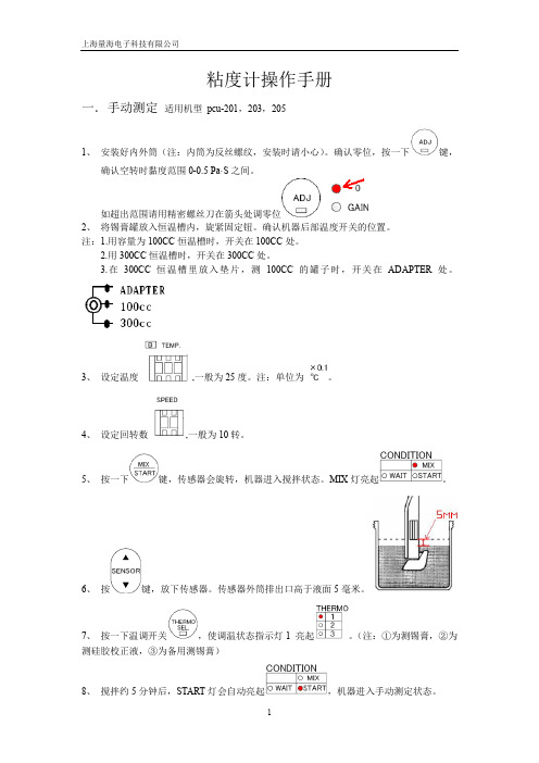
粘度计操作手册一.手动测定适用机型pcu-201,203,2051、安装好内外筒(注:内筒为反丝螺纹,安装时请小心)。
确认零位,按一下键,确认空转时黏度范围0-0.5 Pa·S之间。
如超出范围请用精密螺丝刀在箭头处调零位2、将锡膏罐放入恒温槽内,旋紧固定钮。
确认机器后部温度开关的位置。
注:1.用容量为100CC恒温槽时,开关在100CC处。
2.用300CC恒温槽时,开关在300CC处。
3.在300CC恒温槽里放入垫片,测100CC的罐子时,开关在ADAPTER处。
3、设定温度,一般为25度。
注:单位为。
4、设定回转数,一般为10转。
5、按一下键,传感器会旋转,机器进入搅拌状态。
MIX灯亮起。
6、按键,放下传感器。
传感器外筒排出口高于液面5毫米。
7、按一下温调开关,使调温状态指示灯1 亮起。
(注:①为测锡膏,②为测硅胶校正液,③为备用测锡膏)8、搅拌约5分钟后,START灯会自动亮起,机器进入手动测定状态。
9、待黏度值稳定后,约15分钟,按一下打印键,机器会打印出当前的时间,温度,回转数,黏度等。
10、报警功能(注:此功能为可选项)手动测定时,可选择是否使用此功能。
设定一个黏度值下限,假设为150pa.s(单位为0.1pa.s)。
开始测定后,按一下ALARM开关,开启报警功能。
当测出的黏度值高于150pa.s以后,又跌倒低于150pa.s时,测定停止,报警器响起。
如果想解除警报,按一下ALARM开关。
如将黏度值设为[0000]时,报警功能自动解除。
注:黏度测定精度:指定值的±5﹪。
黏度值重复精度:±0.5﹪。
工作室温:20℃-30℃。
温调范围:室温±5℃,内设恒温槽。
温度设定范围:16℃-34℃。
控温精度:±0.5℃。
零位修正:范围0-0.5 Pa·S。
GAIN 黏度值增益调整,用硅胶校正时,误差范围为±1﹪。
二.J IS规则测定法适用机型PCU-203,2051、安装好内外筒。
粘度计操作指南说明书一、介绍粘度计是一种用于测量液体黏度的实验室仪器。
本指南将详细介绍如何正确操作粘度计,以确保准确和一致的测量结果。
二、操作前的准备工作1. 确保粘度计外观整洁无损,仪器零部件完好。
2. 检查粘度计是否被校准并保持在合适的温度下。
3. 确保工作区域干净整洁,并保持稳定的温度。
4. 使用合适的溶液或样品准备好用于测试的液体。
5. 根据润滑剂的不同,选择合适的测量杯或克氏管。
三、操作步骤1. 将粘度计放置在水平的工作台上,并确保仪器平稳不会晃动。
2. 打开粘度计的电源开关,并等待仪器初始化完成。
3. 使用精密天平或注射器将待测液体准确地倒入测量杯、克氏管或测量槽中,确保液体接触表面充分,不产生气泡。
4. 将液体样品放入粘度计的样品台中,并确保水平和稳定。
5. 调节粘度计的测量温度至所需的设定温度。
根据不同的液体,可以通过冷却或加热操作进行温度调整。
6. 启动粘度测量程序,并等待测量结果显示稳定后进行记录。
记录时间和温度等相关参数。
7. 完成测量后,根据操作指南进行数据分析和记录。
四、粘度计的维护1. 每次使用结束后,将粘度计进行清洁并确保无残留物。
2. 定期校准粘度计以确保准确的测量结果。
3. 当出现故障或错误时,及时联系售后服务进行修复或更换零件。
4. 遵循制造商提供的更多保养和保养细节。
五、操作安全注意事项1. 在操作粘度计时,要遵循所有操作指南和安全规范。
2. 小心处理热液体并避免烫伤。
3. 避免粘度计的震动和碰撞,以免影响仪器的准确性。
4. 使用适当的个人防护设备,如手套和护目镜。
六、总结本操作指南旨在提供对粘度计正确操作的详细说明。
通过正确操作粘度计,可以获得准确和可靠的测量结果,并确保实验的可重复性和准确性。
在使用粘度计之前,请确保熟悉并理解所用仪器的操作指南和相关安全要求。
如有任何疑问或困惑,请咨询制造商或相关专业人士的帮助。
参考文献:[1] 张鹏. 粘度计在油品检测中的应用[J]. 测绘科技装备, 2020, 3(6): 86-88.[2] 卢丹丹, 林沛, 杨瑶. 粘度计在滑动轴承油润滑膜特性测试中的应用[J]. 机械传动, 2018。

、使用说明书本说明书是为方便用户使用"FWS1000型在线液体粘度"监测仪器产品而编写的,说明书的信息已经过仔细校对以保证其准确性,但是不对内容的正确性提供法律保证。
本说明书信息如有变更,恕不另行通知。
深圳市先波科技有限公司FWS1000在线液体粘度监测仪器目录1.概述------------------------------------------------------------(3)2.技术参数----------------------------------------------------------(4)3.结构与外型--------------------------------------------------------(5)4.传感器安装------------------------------------------------------(8)5.操作说明---------------------------------------------------------(10)6.传感器标定--------------------------------------------------------(18)7.运输和贮存--------------------------------------------------------(21)8.装箱单PACKING LIST----------------------------------------------(21)9.附件一:传感器出厂标定参数-------------------------------------(22)10.附件二:FWS-3黏度传感器润滑油粘度标定方案及算法11.附件三.FWS-3黏度传感器润滑油粘度标定方案及算法12.附件四.采集传输装置的使用和通讯协议一、概述本说明书叙述了FWS1000型在线液体粘度监测仪器的标准技术参数、结构及工作原理,安装、操作和维修说明。


Measurable success by Sewerin equipmentCongratulations. You have chosen a quality instrument manufactured by Hermann Sewerin GmbH.Our equipment will provide you with the highest standards of perfor-mance, safety and efficiency. They correspond with the national and international guide-lines.Please read and understand the following operating instructions before using the equipment; they will help you to use the instrument quickly and competently. If you have any queries we are available to offer advice and assistance at any time.YoursHermann Sewerin GmbHRobert-Bosch-Straße 333334 Gütersloh, GermanyTel.: +49 5241 934-0Fax: +49 5241 934-444info@Sewerin Ltd HertfordshireUKPhone: +44 1462-634363 info@ Sewerin USA, LLC 13551 W. 43rd Drive, Unit R Golden, CO 80403-7272 Phone: +1 303-424-3611 Fax: +1 303-420-0033 jerry.palmer@SEWERIN Sarl17, rue Ampère - BP 211 67727 HOERDT CEDEX, France Tél. : +33 3 88 68 15 15Fax : +33 3 88 68 11 77 www.sewerin.frsewerin@sewerin.fr SEWERIN IBERIA S.L.c/ Cañada Real de Merinas, 17 Centro de Negocios …Eisenhower“Edificio 5; Planta 2 - C28042 Madrid, EspañaTel.: +34 91 74807-57Fax: +34 91 74807-58www.sewerin.esinfo@sewerin.esIllustration Glassfibre rod GSK/GFSGlassfibre rod GSKGlassfibre rod GFSOperating Instructions Glassfibre Probe Systems GFS/GSKMini pig transmitterSluices for mini pig transmitter03.03.2008 – V 2 – 102684 – enFor your safetyThis product may only be operated by appropriately-trained persons who are familiar with the relevant operating manual.It may only be used for its designated purpose, i.e. for industrial and com-mercial use.Repair work may only be carried out by specialists or by persons who have undergone appropriate training.Any alterations or modifications to the product require the prior approval of Hermann Sewerin GmbH. In the event of unauthorised alterations to the product the manufacturer accepts no liability for damage.Only Hermann Sewerin GmbH accessories may be used with the product. Only spare parts approved by us may be used for repairs.Hermann Sewerin GmbH accepts no liability for damage resulting from non-compliance with the foregoing. The guarantee and liability provisions in the Hermann Sewerin GmbH terms of sale and supply are not extended by the foregoing.We reserve the right to make changes in the context of continued techni-cal development.In addition to these instructions, please comply with generally applicable safety and accident-prevention regulations!Symbols used:Contents Page1 G lassfibre probe systems GFS/GSK (1)1.1 Purpose (1)1.2 Construction (1)1.3 Components of the location device (1)1.4 Inducing a field in the glassfibre rod and locating it (2)2 Mini pig transmitter (3)2.1 Purpose (3)2.2 Mini pig transmitter "A" (3)2.3 Mini pig transmitter "B" (4)2.4 End-point determination with the FS3A probe and the mini pigtransmitter (5)3 Sluice (6)3.1 Purpose (6)3.2 Components of the sluice (6)3.3 Installation (7)1 Glassfibre probe systems GFS/GSK1Glassfibre probe systems GFS/GSK 1.1 PurposeThe glassfibre probe systems are used in conjunction with a com -mercially available pipeline-location device (such as the SEWERIN FERROPHON ) to locate non-metallic pipeline systems.1.2 ConstructionInside the flexible glassfibre rod there are conducting wires which serve to determine the path of the pipeline.The connection socket on the reel hub connects the glassfibre probe to the generator (transmitter).The brass tip on the end of the rod enables it to be used with very small radii (down to the radius of the reel).1.3 Components of the location deviceThe location device consists of the following components:generatorreceiver with headphones or loudspeaker,search coil (if not integral to the receiver) andGFS or GSK glassfibre rod.●●●●1 Glassfibre probe systems GFS/GSK1.4 Inducing a field in the glassfibre rod and locating itComply with the instructions in the generator manual. In principle the induction of an electrical field in a glassfibre cable is no diffe -rent from galvanic induction in a pipeline (cf. fig. 1).Fig.1 - Set-up for determining the pipeline pathIn order to receive a clean signal the following points should be observed:the further the rod is pushed in, the higher the initial level (trans-mission current) should be setthe signal quality can be substantially improved if there is a little water in the pipeline system.The path of the pipeline can now be determined in the same way as that of a pipeline with a galvanically induced electrical field (also the FERROPHON operating instructions).●●2 Mini pig transmitter 2 Mini pig transmitter2.1 PurposeThe mini pig transmitter serves to determine the position of thetip of the GFS and GSK glassfibre rods. It generates an electro-magnetic alternating field which can be located with a pipeline-location device.2.2 Mini pig transmitter "A"The mini pig transmsitter "A" can be externally distinguished fromother mini pig transmsitters by the groove running round it (item1) on the pig screw-joint (item 2).The transmission frequency is "A", i.e. approximately 41.6 kHz.This frequency must be set at the receiver.The mini pig transmsitter is switched on by screwing it onto theglassfibre rod. It must be unscrewed again after use, otherwiseit remains in operation.To change the battery unscrew the pig housing (item3) and fitthe new battery as shown.Hint: the function of the mini pig transmsitter should be checkedbefore it is used. In order to avoid misleading displays this shouldbe done in the open air in an undisturbed environment; conduct-ing parts (steel sheathing) in the ground deflect the electromag-netic field.The location of the mini pig transmitter is described in the receiveroperating instructions.2 Mini pig transmitterMini pig transmitter "A"length: approx. 103 mmdiameter: approx. 15 mmbattery : lithium, 3V, 160 mAh, order no. 1355-0008operating time: 9 ... 12 hourslocation depth: up to approx. 6 m2.3 Mini pig transmitter "B"The mini pig transmitter "B" can be externally distinguished fromother mini pig transmsitters by the fact that it has no groove run-ning round it on the pig screw-joint (cf. the mini pig transmitter"A").The mini pig transmsitter is switched on by screwing it onto theglassfibre rod. It must be unscrewed again after use, otherwiseit remains in operation.To change the battery the mini pig transmsitter must be un-screwed. The battery must be placed in the black pig housing sothat the positive terminal is visible.The transmission frequency is "B", i.e. approximately 10 kHz.This frequency must be set at the receiver (e.g. type E6 or E4B).Mini pig transmitter "B"length: approx. 105 mmdiameter: approx. 15 mmbattery : e.g. Varta V13HM 1.4 V, order no. 1356-0001operating time: approx. 50 hourslocation depth: approx. 1.5 m2 Mini pig transmitter2.4End-point determination with the FS3A probe and the mini pig transmitterEnd-point determination is carried out by the "minimum method". The following illustration shows how the signal changes at the receiver.You are recommended not to induce an electrical field in the glassfibre rod during end-point determination (switch the gen -Signal at receiverPosition of the FS3A search coilLocation of the mini pig transmit-ter in the pipein the pipe63 Sluice3 Sluice3.1 PurposeThere is a special sluice for each glassfibre probe system (GFSand GSK).This enables the glassfibre rod to be introduced into pressurisedlines in the region of the building junction.3.2 Components of the sluiceThe sluice consists of the following individual components (fig. 4):② 1 connector piececonnector piece③ 1 connection nippleconnection nipple④ 1 valve nut⑤ 4 compressors⑥ 2 rubber seals and⑦ 1 sealing ringItem ① depicts the glassfibre rod with mini pig transmsitter.Fig. 4 - components of the sluice3 Sluice3.3 InstallationFig. 5 shows how the sluice with the glassfibre probe ① is mountedon the stop valve ⑧.Step 1Step 2Step 3Fig. 5 - assembling the sluice7Hermann Sewerin GmbHRobert-Bosch-Straße 3 · 33334 Gütersloh · Germany Telefon +49 5241 934-0 · Telefax +49 5241 ·****************03.03.2008 – 102684 – e n。

德国MARIMEX粘度计VA-300MMARIMEX粘度计公司1984年在加拿大成立,开始研制并生成在线粘度计,在德国开办了MARIMEX 粘度计公司,德国MARIMEX粘度计公司经过多年的积累,在化工、食品等行业得到应用。
MARIMEX粘度计如今已成为在线粘度计领域的一个响亮的品牌。
Marimex 粘度计ViscoScope ® 在线粘度计是一个模块化的测量系统,其提供简单的,实时的复杂的参数“粘度”和工业应用的免维护的监控。
MARIMEX粘度计ViscoScope ® 过程粘度计采用模块化设计,从-40°C到450°C的温度下(或到1500°C),压力从真空到550 bar,粘度从0.1到2,500,000 mPa·s ,MARIMEX粘度计的解决方案可以满足客户的工艺要求,安装可以根据客户要求制作法兰。
MARIMEX粘度传感器通过ATEX / IECEx。
产品应用:涂料油漆和清漆精细化学品胶粘剂和密封胶合成树脂纸涂料聚合物(PET,PE,PC,PA6,PIB,PS,PMMA等)聚合物熔体(纤维,颗粒)硅悬浮液,分散液,乳液黑酒水泥产品功能介绍:ViscoScope在线粘度计,实时测量粘度和温度参,MARIMEX在线粘度计适用于连续过程和间歇过程,在连续过程中,将对粘度进行持续监控。
MARIMEX在线粘度计允许例如在敞开式涂料系统中计量溶剂,调节介质温度,获得恒定粘度(胶粘剂应用)或确定分子量分布。
MARIMEX在线粘度计通常应用是用在混合或反应过程,粘度曲线或想要到规定的目标粘度过程(均质化或停止反应)。
MARIMEX模块化过程粘度计可用于很多工业领域,从简单的标准安装到定制的情况。
如果你不能连接变送器和过程控制系统,或者使用过程中粘度计为一个单独的系统,ViscoView ®软件可以为您记录数据。
主要产品:MARIMEX粘度计,MARIMEX粘度探头,MARIMEX粘度传感器,MARIMEX在线粘度计,MARIMEX 黏度仪,marimex传感器,MARIMEX控制器,MARIMEX变送器,MARIME在线粘度计产品介绍:MARIMEX粘度传感器VA-100和VA-300:ViscoScope ®传感器由不锈钢组成,与过程接触的部件焊接,以阻止部件活动磨损或泄漏。