
ECEI-U01_3W-P
- 格式:ppt
- 大小:2.04 MB
- 文档页数:5


GigaSPEED XL® 3071E-B ETL Verified Category 6 U/UTP Cable, lowsmoke zero halogen, white jacket, 4 pair count, 1000 ft (305 m) length,reelProduct ClassificationRegional Availability EMEAPortfolio SYSTIMAX®Product Type Twisted pair cableProduct Brand GigaSPEED XL®General SpecificationsProduct Number3071EANSI/TIA Category6Cable Component Type HorizontalCable Type U/UTP (unshielded)Conductor Type, singles SolidConductors, quantity8Jacket Color WhitePairs, quantity4Separator Type BisectorTransmission Standards ANSI/TIA-568.2-D | CENELEC EN 50288-6-1 | ISO/IEC 11801 Class E DimensionsCable Length304.8 m | 1000 ftDiameter Over Insulated Conductor 1.041 mm | 0.041 inDiameter Over Jacket, nominal 5.918 mm | 0.233 inJacket Thickness0.559 mm | 0.022 inConductor Gauge, singles23 AWG13Page ofCross Section DrawingElectrical Specificationsdc Resistance Unbalance, maximum 5 %dc Resistance, maximum7.61 ohms/100 m | 2.32 ohms/100 ftDielectric Strength, minimum2500 VdcMutual Capacitance at Frequency 5.6 nF/100 m @ 1 kHzNominal Velocity of Propagation (NVP)70 %Operating Frequency, maximum300 MHzOperating Voltage, maximum80 VRemote Powering Fully complies with the recommendations set forth by IEEE 802.3bt (Type4) for the safe delivery of power over LAN cable when installed accordingto ISO/IEC 14763-2, CENELEC EN 50174-1, CENELEC EN 50174-2 or TIATSB-184-ASegregation Class cMaterial SpecificationsConductor Material Bare copperInsulation Material PolyolefinJacket Material Low Smoke Zero Halogen (LSZH)Separator Material PolyolefinPage of23Mechanical SpecificationsPulling Tension, maximum11.34 kg | 25 lbEnvironmental SpecificationsInstallation temperature0 °C to +60 °C (+32 °F to +140 °F)Operating Temperature-20 °C to +60 °C (-4 °F to +140 °F)Acid Gas Test Method EN 50267-2-3EN50575 CPR Cable EuroClass Fire Performance B2caEN50575 CPR Cable EuroClass Smoke Rating s1aEN50575 CPR Cable EuroClass Droplets Rating d0EN50575 CPR Cable EuroClass Acidity Rating a1Environmental Space Low Smoke Zero Halogen (LSZH)Smoke Test Method IEC 61034-2Packaging and WeightsCable weight38.097 kg/km | 25.6 lb/kftPackaging Type ReelRegulatory Compliance/CertificationsAgency ClassificationCENELEC EN 50575 compliant, Declaration of Performance (DoP) availableCHINA-ROHS Below maximum concentration valueISO 9001:2015Designed, manufactured and/or distributed under this quality management system REACH-SVHC Compliant as per SVHC revision on /ProductCompliance ROHSCompliantPage of33。
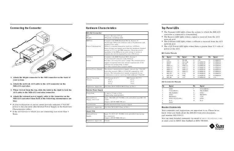
Connecting the Converter1.Attach the40-pin connector to the MII connector on the back ofyour system.2.Attach the network AUI cable to the AUI connector on theMII-AUI converter.3.When viewed from the top,slide the latch to the right to lock theAUI cable to the MII-AUI converter connector.4.Attach the external power supply cable to the connector on theMII-AUI converter when both of the following circumstances are true:•If your workstation or server cannot provide sufficient5Volt DC power to the converter.(See Internal Power Supply in the Hardware Characteristics table.)•If the AUI device to which you are connecting uses more than4 Watts.Hardware Characteristics Top Panel LEDs•The Transmit LED lights when the system to which the MII-AUIconverter is connected is transmitting.•The Receive LED lights when a signal is received from the AUInetwork port.•The Collision LED lights when a collision is received from the AUInetwork port.•The+12V Power LED lights when there is greater than11.3volts ofpower at the AUI.MII Cable PinoutsAUI Connector PinoutsReader CommentsYour comments and suggestions are important to us.Please let usknow what you think about the MII-AUI Converter document,part number802-5358-13.You can send detailed comments via email to*****************,or send a fax to SMCC Doc Feedback at(650)786-6443.MII-AUI ConverterSizeWeight7.6cm x10.2cm x2.5cm300grams,including cableMII PortPower ConsumptionComplies with IEEE Standard802.3u,Section2240pin male.050in.D connector with2-56jackscrews andintegral19in.cable.200mA+external transceiver load(see AUI Port)Some systems can supply more than the minimum requiredcurrent of.75A to the MII connector.Check the powercapability of the MII port on your system to ensure itsupplies the current required by your AUI device.AUI PortPowerComplies with IEEE Standard802.3,Section715pin female D connector with slidelockProvides+12volt power at0-.5amps.The external powersupply is required when the current requirements of theAUI port are greater than.2amps.Use with a Listed Class2power supply.Internal Power Supply The device’s internal power supply converts the5Volt DCfrom your system’s MII to12Volt DC required by AUIdevices.The external power supply is required if yourworkstation or server cannot provide sufficient5Volt DC.Typical OperatingCurrentAUI Current@12V MII Current@4.75V0.0A0.2A0.25A 1.0A0.5A 1.8ARegulatory Approvals UL/CSA/TUV/VCCI2/FCC Class A/CE AExternal Power SupplyPower Jack 2.1mm x5.5mm x12mOutput plug center positiveExternal PowerSupply:UniversalInput:100-240V AC/50-60Hz with embedded male IEC320socketOutput:12V DC REG500mAClassification Double-insulated Class2power supplyRegulatory Approvals UL/CSA/TUV/FCC Class A/CE AJapan OnlyExternal PowerSupplyInput:91-110V AC,50-60Hz with embedded dual prongflat connectorsOutput:12V DC REG500mARegulatory Approvals T-markPin Signal Pin Signal Pin Signal Pin Signal12345678910+5VMDIOMDCRXD<3>RXD<2>RXD<1>RXD<0>RX_DVRX_CLKRX_ER11121314151617181920TX_ERTX_CLKTX_ENTXD<0>TXD<1>TXD<2>TXD<3>COLCRS+5V21222324252627282930+5VCOMMONCOMMONCOMMONCOMMONCOMMONCOMMONCOMMONCOMMONCOMMON31323334353637383940COMMONCOMMONCOMMONCOMMONCOMMONCOMMONCOMMONCOMMONCOMMON+5VPin Signal Pin Signal12345678GNDCOLLISION+TRANSMIT+GNDRECEIVE+GND(VOLTAGE-)N/CGND9101112131415COLLISION-TRANSMIT-GNDRECEIVE-+12VGNDN/CRecycled PaperFCC Class A Notice —United StatesThis device complies with Part 15of the FCC Rules.Operation is subject to the following two conditions:1.This device may not cause harmful interference.2.This device must accept any interference received,including interference that may cause undesired operation.Note –This equipment has been tested and found to comply with the limits for a Class A digital device,pursuant to Part 15of the FCC Rules.These limits are designed to provide reasonable protection against harmful interference when the equipment is operated in a commercial environment.This equipment generates,uses and can radiate radio frequency energy and,if not installed and used in accordance with the instruction manual,may cause harmful interference to radio communications.Operation of this equipment in a residential area is likely to cause harmful interference in which case the user will be required to correct the interference at his own expense.Shielded CablesConnections between the workstation and peripherals must be made using shielded cables in order to maintain compliance with FCC radio frequency emission limits.ModificationsModifications to this device,not approved by Sun Microsystems,Inc.,may void the authority granted to the user by the FCC to operate this equipment.Canadian Class A Notice -Avis Du Minestère des Communications,Classe AThis Class A digital apparatus meets all requirements of the Canadian Interference-Causing Equipment Regulations.Cet appareil numérique de la classe A respecte toutes les exigences du Règlement sur le matériel brouilleur du Canada.MII-AUI ConverterAbout the MII-AUI ConverterThe MII-AUI Converter allows the use of an existing AUI (Attachment Unit Interface)network connection with a system that uses an MII (Media Independent Interface)for its network connection.The converter is compatible with Sun™Ultra™platforms and SunFastEthernet™adapters with an available MII port.Part Number: 802-5358-13Revision A of November 1997©1997Sun Microsystems,Inc.All rights reserved.Sun,Sun Microsystems,the Sun Logo,SunSoft,and Solaris are trademarks or registered trademarks of Sun Microsystems,Inc.in the United States and in other countries.©1997Sun Microsystems,Inc.Tous droits réservés.Sun,Sun Microsystems,le logo Sun,SunSoft,et Solaris sont des marques déposées ou enregistrées de Sun Microsystems,Inc.aux Etats-Unit et dans d’autres pays.。

EXTECH.INSTRUMENTS User ManualExtech Model IR320Waterproof, Dual Laser IR Thermometer with Alarm1.IntroductionThank you for selecting the Extech IR320 IR Thermometer. The IR320 is a professional non-contact infrared thermometer that measures surface temperature from infrared energy radiated by the target's surface. We ship this meter fully tested and calibrated and, with proper use, it will provide years of reliable service. Please visit our website () for the latest version of this User Manual and Customer Support.2.Product FeaturesStrong and Durable: 3m (9.8 ft.) drop-proofDustproof and Waterproof: IP65Ergonomic Design: Comfortable handheld, simple and convenient operationMAX/MIN/AVG/DIF values: Quickly display the Maximum, Minimum, Average (running average updates every two readings), and Differential (Max minus Min) valuesLarge Backlit LCDTripod mount for hands-free operationAlarm Function: High/Low temperature alarm provides flashing color-coded LED indicators when triggeredDual Laser Pointers: To enhance measurement target accuracy3.Safety Instructions� WARNINGTo avoid personal injury, please read the following safety information before using this product:•Safety Standards Compliance:CE Identification: EN 61326-1: 2013, EN 61326-2-3: 2013Laser Safety Standard: Complies with 21 CFR 1040.10 and 1040.11 except for deviations pursuant to laser notice no. 50 dated June 24, 2007•Please do not point the laser toward people or anima l s directly or indirectly.•Please do not look at the laser directly or through other optical tools (telescope, microscope, etc.).•If the battery symbol on the LCD display is flashing, replace the batteries immediately to avoid inaccurate measurements.•Before using the product, check the product for damage. Do not use this product if obvious physical damage is apparent.•Refer to the Table of Emissivity Factors for Common Materials in this manual before taking measurements. Reflective objects will cause the measured value to be lower than the actual temperature value. Set the emissivity to match each given surface type. When measuring, please do not touch high temperature surfaces.•Do not use this product near explosive gases.•To ensure measurement accuracy, place this product in the test environment for more than 30 minutes before use.•Avoid keeping the thermometer near high temperature objects for long periods.1&LAIBIUIHTDO IIR'IIME 111111--.eu112LA1B1PRIIDUCT IIAI CIUJIIUIPIMBl<I ..WAIB.BII:--CXM'I.IESWllll 21 CFII1040. 10AII) 1040.11 EJaPI' FCII IIE'Mlll PIIISIWIlO LASBI NlfflCE NO. IIO MIED.DIE 24, 211117.IR320-en-GB_ V l.O f{18Test Equipment Depot - 800.517.8431 - 99 Washington Street Melrose, MA 02176 - 5.OperationPower On and OffPull the trigger to power the meter, the LCD (and backlight) will turn on. The thermometer will power off automatically after approximately eight (8) seconds.Manual Measurements1.Pull and hold the trigger after aiming toward the target to measure.2.The SCAN icon will flash while measuring the targeted surface or object. The center of the measurement spot is equidistant between the two laser points (enable/disable lasers per the Lasers Enable/Disable section).3.Read the temperature measurement on the large digits at the center of the LCD.4.Release the trigger. The SCAN icon disappears and the HOLD icon appears, indicating that the measurement has stopped and the display is holding the last measured value. The meter will power off automatically after approximately eight (8) seconds.Automatic Measurements (trigger-free)MAX/MIN/AVG/DIF ValuesWith the meter ON, short press the RCL (Recall) button to step through the MAX/MIN/AVG/DIF modes respectively; the display will show the value of the corresponding mode in the secondary display area (lower right). The MAX value is the highest reading taken in a given measurement session, the MIN value is the lowest reading, the AVG value is a running average that updates every two readings, and the differential (DIF) is the MAX minus MIN value.Alarm ActivationWith the meter ON, short press the HI/LO button to select the HI-LO alarm mode, HI-only alarm mode, LO-only alarm mode, or no alarm mode (the display icons will inform as to what mode is currently selected: HI, LO, HI-LO, or no icons). When you select the HI alarm mode, the HI LED will flash red when the measured temperature exceeds the high alarm limit. When you select the LO alarm mode, the LO LED will flash blue when the measured temperature is lower than the low alarm limit. When you select the HI-LO alarm mode, the HI or LO LED will flash depending on whether the measured temperature is higher than the HI limit or lower than the LO limit.HIGH and LOW Alarm Limit SettingWith the meter ON, short press the M button once to access the HI alarm screen or press M twice to step to the LO alarm screen. Use the up/down buttons to set the alarm thresholds. Short press the up/down buttons to add or subtract 1 unit, long press to change the units rapidly. The meter will exit the setup screen automatically after five (5) seconds of button inactivity.3 IR320-en-GB_V1.0 6/187.Emissivity ConsiderationsThe Emissivity setting is shown in small digits at the lower left corner of the display. To adjust the Emissivity please refer to the Emissivity Setting section. Emissivity represents the reflectivity of a material. Most organic materials and painted or oxidized surfaces have an emissivity of approximately 0.95. Masking tape or flat black paint should be applied to cover the measured surface. Wait a period of time to allow the tape or paint to reach thermal equilibrium with the surface of the covered object. Measure the temperature of the surface covered with tape or paint only after equilibrium has been achieved.I M easured Surfaces MetalsAluminumOxidization A3003 AlloyOxidizationRough BrassBurnishingOxidization CopperOxidization Table of Emissivity Factors for Common MaterialsI E missivity0.2-0.40.30.1-0.30.30.50.4-0.811 M easured SurfacesNon-MetalsAsbestosAsphaltBasaltCarbonNon-OxidizationElectric Terminal Board 0.6 GraphiteSilicon Carbide Hastelloy CeramicsAllov 0.3-0.8lnconel ClayOxidization 0.7-0.95Sand-Blasting 0.3-0.6Electro Burn i sh i ng 0.15Iron Concrete Oxidization 0.5-0.9Rusting 0.5-0.7Iron (Casting) Cloth Oxidization 0.6-0.95Non-Oxidization 0.2Casting 0.2-0.3Iron (Forging) Glass Passivation 0.9 Convex GlassSmooth GlassLead-Boron Glass lead Plates Rough 0.4Oxidizat i on 0.2-0.6Molybdenum Stone Products Oxid i zation 0.2-0.6Nickel Plaster Ox i dization 0.2-0.5Plat i num IceBlack 0.9Steel Limestone Cold rolling 0.7-0.9Steel Plate Burnishing 0.4-0.6Steel Plate Rubbing 0.1Zinc Paper Oxidizat i on 0.1PlasticsWaterSoilWood5 Emissivity I I 0.950.950.70.8-0.90.7-0.80.90.950.950.950.90.76-0.80.92-0.940.78-0.820.960.930.8-0.950.980.980.950.950.930.9-0.980.9-0.95IR320-en-GB_ V l.O f{18Test Equipment Depot - 800.517.8431 - 99 Washington Street Melrose, MA 02176 - 9.SpecificationsSafety Standards ComplianceCE Identification: EN 61326-1: 2013, EN 61326-2-3: 2013Laser Safety Standard: Complies with 21 CFR 1040.10 and 1040.11 except for deviations pursuant to laser notice no.50 dated June 24, 2007Test Equipment Depot - 800.517.8431 - 99 Washington Street Melrose, MA 02176 - 7 IR320-en-GB_V1.0 6/18。