静态管道混合器技术说明(第二版)
- 格式:docx
- 大小:13.58 KB
- 文档页数:2

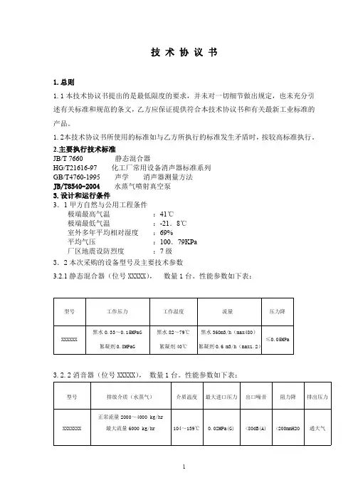
管道静态混合器技术描述1. 总述静态管道混合器主要用于自来水厂城镇污水处理厂的加药混合,是一种让水流突然改变流向,造成水力碰撞的混合装置。
设备一般由2节或3节单体管组成,相互之间正逆向交叉组合,介于管道中间,并与管道法兰连接,使投加的药剂在管道内瞬时充分混合。
2. 供货范围管道静态混合器的安装需要和使用需要的全部螺栓、螺母、垫圈和密封垫片等连接件或紧固件。
带配对法兰和链接螺栓。
主要供货清单:3. 技术参数及条件管道静态混合器,DN1000和DN800各一套。
4. 设备材质·筒体:S304不锈钢·混合单体:S304不锈钢·加药管:S304不锈钢·紧固件:S304不锈钢·两端法兰:S304不锈钢5. 设计与结构管道混合器由筒体、法兰、混合单体加药口组成。
混合器设1只的加药口。
加药管应伸入混合器内1/30处,即提高混合效果,又不使口子腐蚀。
叶片形状为四分之一椭圆,与筒体接后,其弧形面必须与筒体内壁相吻合。
管道混合器水力损失应≤0.5m。
6. 抗腐蚀整体采用不锈钢304制作。
所有不锈钢机件须经酸洗后涂银白色的金属漆。
7. 测试与检验严格进行厂内各生产环节的检验和试验。
提供的合同设备签发质量证明、检验记录和测试报告,并且作为交货时质量证明文件的组成部分。
试验的内容:1)材料试验:材料应根据标准试验。
2)工厂试验负责制造期间和装运前的必要的试验。
关键部件进行材料试验,并提供报告。
3)现场试验在设备完全安装好后,进行必要的试验,并按验收标准进行。
进行这些试验的时候,派人到现场帮助,解决试验暴露的缺陷。
直到合格为止。
8. 设备制造标准该产品在设计、制造、检验、包装运输及安装过程中所遵循的通用标准均为国标(GB)或部标(JB)法兰执行标准HG20640-97。
JB2932-86 水处理设备制造技术条件CJ/T3061-1996 水处理用溶药搅拌设备GB50231-98 机械设备安装工程施工及验收通用规范JB/ZQ4000.2-86 切削加工件通用技术条件JB/ZQ4000.3-86 焊接件通用技术条件JB/ZQ4000.5-86 铸件通用技术条件JB/ZQ4000.7-86 锻件通用技术条件JB/T5000.5-98 有色金属铸件通用技术条件JB/ZQ4000.9-86 装配技术条件JB/ZQ4000.10-86 涂装通用技术条件JB/ZQ4286-86 包装技术通用技术条件GB3797-89 装有电子器件电控箱技术条件GB8923-85 涂装前钢材表面锈蚀等级和除锈等级GB4879-99 防锈包装YJ010 抛丸喷砂技术条件及检验方法JB/ZQ4000.1-86 产品检验通用技术要求。

静态混合器静态混合器_(NXPowerLite)1、概念静态混合器是一种新型先进的化工单元设备,自70年代开始应用后,迅速在国内外各个领域得到推广应用。
众所周知,对于二股流体的混合,一般用搅拌的方法。
这是一种动态的混合设备,设备中有运动部件。
而静态混合器内主要构件静态混合单元在混合过程中自身并不运动,而是凭借流体本身的能量并借助静态混合单元的作用使流体得到分散混合,设备内无一运动部件。
2、流体的混合机理对于层流和湍流等不同的场合,静态混合器内流体混合的机理差别很大。
层流时是“分割---位置移动---重新汇合”的三要素对流体进行有规则的反复作用,从而达到混合;湍流时,除以上三要素外,由于流体在流动的断面方向产生剧烈的涡流,有很强的剪切力作用于流体,使流体的细微部分进一步被分割而混合。
3、静态混合器的混合形态静态混合器在基本工艺流程中的组合方法见下图所示的两种类型。
在实际应用中往往将多种基本流程组合在一起使用。
两种液体汇合部位的结构,应根据液体的粘度、密度、混合比、互溶性等来确定。
尤其当两种液体一接触就反应或凝胶而相变时,更要注意汇合部位的结构、流速以及混合器的选择。
3.1层流的混合经静态混合器混合后的流体的混合形态,与经具有传动部件的混合机或搅拌机混合的混合形态有明显的差别。
图二表示采用静态混合器混合两种流体是产生的典型层流混合状态。
混合状态由条带状变为连续的或不连续的线状及粒子状,而状态的变化取决于流体混合时的雷诺数和韦伯数。
例如:当流速、粘度、混合器直径一定时,如果流体间表面张力大,流体的混合形态则从条带状转向线状,进而变化到粒子状。
混合器单元数、管径和流速的选定混合器的单元数和直径随流体的性质(粘度、互溶性、密度)、混合比、希望达到的混合状态、接触面上液体的结构变化等而不同,可通过试验和经验来确定。
通常基于雷诺数并经试验确定混合器的放大倍数。
但当雷诺数R e<100(严格地说在1以下)时,混合程度、混合状态与雷诺数无关,只取决于混合器的单元数。
静态混合管的工作原理一、引言静态混合管是一种高效的流体混合设备,能够在不使用任何移动部件的情况下,实现对流体的有效混合。
它在化工、石油、制药等多个领域有着广泛的应用,特别是在需要两种或多种流体进行快速、均匀混合的场合。
本文将详细探讨静态混合管的工作原理,包括其内部构件、流体分割与重新排列机制、多方向流动的引入等方面的内容。
二、工作原理概述静态混合管的基本工作原理是利用流体的物理性质,通过特殊的内部结构设计,使流经管路的流体在管内进行分割、重组,从而实现流体的均匀混合。
这种混合过程是在流体流动过程中自然发生的,不需要任何外部驱动装置或额外的能量输入。
三、内部构件与设计静态混合管的内部结构是其实现流体混合的关键。
一般来说,静态混合管由一系列的固定元件组成,如螺旋片、折流片、异形片和十字交叉片等。
这些元件按照一定的排列方式装配在管路中,形成了特定的流动通道。
这些元件的设计和排列方式,直接决定了流体在管内的流动状态和混合效果。
四、流体的分割与重新排列在静态混合管中,流体的分割与重新排列是实现混合的关键步骤。
当流体流经这些特殊设计的元件时,流体会被分割成若干个小股流束,并在元件的作用下改变流动方向和速度。
由于不同股流束之间存在着速度差和相互碰撞,使得流体在流动过程中不断进行混合。
此外,通过特殊设计的元件,还可以实现流体的旋转运动,进一步促进流体的均匀混合。
五、多方向流动的引入为了提高混合效果,静态混合管还采用了多方向流动的引入机制。
通过内部元件的特殊设计和排列,可以使得流经管路的流体在多个方向上产生分流和合流,从而实现更高效的混合。
这种多方向流动的引入,不仅可以增加流体之间的碰撞机会,还能提高流体的湍流度,有利于流体的均匀混合。
六、应用与优势静态混合管因其高效、可靠的流体混合性能,在许多领域得到了广泛应用。
例如,在石油工业中,静态混合管可用于将两种或多种油品进行均匀混合;在制药行业,它可以用于制备药物溶液;在环保领域,它可以用于废水的处理和净化。
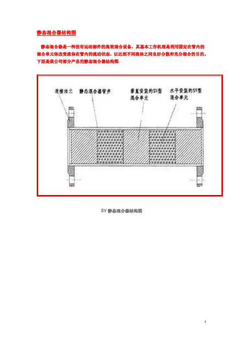
静态混合器结构图静态混合器是一种没有运动部件的高效混合设备,其基本工作机理是利用固定在管内的混合单元体改变流体在管内的流动状态,以达到不同流体之间良好分散和充分混合的目的。
下面是我公司部分产品的静态混合器结构图。
SV静态混合器结构图SK静态混合器结构图SX静态混合器结构图SH静态混合器结构图SY静态混合器结构图煤气静态混合器结构图静态混合器配套SN分配器结构图静态混合器原理一、静态混合器原理静态混合器的混合过程是由一系列安装在空心管道中的不同规格的混合单元进行的。
由于混合单元的作用,使流体时而左旋,时而右旋,不断改变流动方向,不仅将中心液流推向周边,而且将周边流体推向中心,从而造成良好的径向混合效果。
与此同时,流体自身的旋转作用在相邻组件连接处的接口上亦会发生,这种完善的径向环流混合作用,使物料获得混合均匀的目的。
本静态混合器按行业标准JB/T7660-95《静态混合器》设计、制造与验收。
静态混合器可应用于液- 液、液- 气、液- 固、气- 气的混合、乳化、中和、吸收、萃取、反应和强化传热等工艺过程,可在很宽的粘度范围内不同的流型(层流、过渡流、湍流)状态下应用,用于间歇操作和连续操作。
下面先简单介绍不同应用情况的范围。
(1) 液- 液混合从层流至湍流,粘度在106mPa·s 的范围内的流体都能达到良好的混合。
分散液滴最小直径可达到1 ~2μm,且大小分布均匀。
(2) 液- 气混合静态混合器可以使液- 气两相组分的相界面连续更新和充分接触,在一定条件下可代替鼓泡塔和筛板塔。
(3) 液- 固混合当少量固体颗粒或粉末(固体占液体体积的5% 左右)和液体在湍流条件下混合,使用静态混合器,可强制固体颗粒或粉末充分分散,能达到使液体萃取或脱色的要求。
(4) 气- 气混合可用于冷、热气体的混合,不同气体组分的混合。
(5) 强化传热由于静态混合器,增大了流体的接触面积,即提高了给热系数,一般来说对气体的冷却或加热,如果使用静态混合器,气体的给热系数可提高8 倍;对于粘性液体的加热,给热系数可提高5 倍;对于有大量不凝性气体存在的气体冷凝时,给热系数可提高8.5 倍;对于高分子熔融体的换热可以减少管截面上熔融体的温度和粘度梯度。

静态混合器的工作原理混合器技术指标可选中1个或多个下面的关键词,搜索相关资料。
也可直接点“搜索资料”搜索整个问题。
静态混合器的工作原理,就是让流体在管线中流动冲击各种类型板元件,加添流体层流运动的速度梯度或形成湍流,层流时是“分割—位置移动—重新汇合”,湍流时,流体除上述三种情况外,还会在断面方向产生猛烈的涡流,有很强的剪切力作用于流体,使流体进一步分割混合,最后混合形成所需要的乳状液。
之所以称之为“静态”混合器,是指管道内没有运动部件,只有静止元件。
静态混合器的混合过程是由一系列安装在空心管道中的不同规格的混合单元进行的。
由于混合单元的作用,使流体时而左旋,时而右转旋,不断更改流动混合机方向,不仅将中心流体推向周边,而且将周边流体推向中心,从而造成良好的径向混合效果。
与此同时,流体自身的旋转作用在相邻组件连接处的接口上亦会发生,这种完善的径向环流混合作用,使物料获得混合均匀的目的。
静态混合器是一种没有运动的高效混合设备,通过固定在管内的混合单元内件,使二股或多股流体产生切割、剪切、旋转和重新混合,达到除湿机流体之间良好分散和充分混合的目的。
SV型单元是由确定规格的波纹板组装而成的圆柱体,最高分散程度为1—2mm,液液相及气气相适用于粘度 102厘泊的液液、液气、气气的混合乳化,反应、吸取、萃取、强化传热过程。
单元由单孔道左、右扭转的螺旋片组焊而成,最高分散程度10um,液-液、液翻译公司固相不均匀度系数。
适用于化工、石油、制药、食品、精细加工、塑料、环保、合成纤维、矿治等部门的混合、反应、萃取、吸取、注塑、配色传热等过程。
对较小流量并拌有杂质或粘度106厘泊的高粘性介质成为适用。
单元由交叉的横条按确定规律构成很多X型单元,技术特性:混合不均匀度数为s。
适用于粘度104厘泊的中高粘度液液反应、混合、吸取过程肝癌或生产高聚物流体的混合、反应过程,处理量较大时使用效果更佳。
单元是由双孔道构成,孔道内放置螺旋片,相邻单元双孔道的方位错位90 单元之间设有流体再调配室。
管道混合器的安装及常见规格介绍管道混合器,是一种节能而方便的混合方式。
可应用于多种行业上,对于管道混合器而言,大家应该也有所了解吧,对于管道混合器大家知道如何安装吗?管道混合器的常见规格又有那些呢?下面我们一起来看看吧。
和作用原理管道混合器一般由管道分别与喷嘴、涡流室、多孔板或异形板等促进混合的原件组成,一般三节管道连用,作为一个单元(也可根据混合介质的性能增加节数)。
混合的方法有3种,分别为喷嘴式,涡流式,多孔板、异形板式。
对于常见的静态螺旋片式混合器,是在多孔板、异形板式混合器上发展而来,每节混合器有一个180°扭曲的固定螺旋叶片,分左和右两种。
相邻两节中的螺旋叶片旋转方向相反,并相错90°。
为便于安装螺旋叶片,筒体做成两个半圆形,两端均用法兰连接,筒体缝隙之间用环氧树脂粘合,保证其密封要求。
管道内螺旋叶片是固定的,流体通过它产生流向变。
管道混合器的安装:其实针对于管道混合器的安装,对于不了解、没有接触过的朋友而言,想必就像无头苍蝇一样,找不到方法,有的甚至可能说提到这个名字就不知道如何安装,其实对于管道混合器的安装还是非常方便的,在安装的过程当中,它不会受到方向的限制,只要保证水平、垂直等形式就行,当然这里大家需要注意,如果是将管道混合器安装在架空管道上的时候,一定要用支架来将其固定。
管道混合器的常见规格:上述我们介绍到了关于管道混合器的安装问题,接下来我们来看看关乎管道混合器的的常见规格,同时在为大家介绍一些关于材质的问题,一般管道混合器的材质有很多,比如说不锈钢材质、pvc材质、玻璃钢材质以及碳钢衬胶材质等等,针对于不同材质的管道混合器,其常见规格尺寸不同,比如说不锈钢材质常见的尺寸有DN50-DN1500,而常见尺寸有DN200-DN1500,玻璃钢材质的常见规格有DN50-DN300等等。

管道混合器 The latest revision on November 22, 2020管道混合器1介绍2构造原理3适用范围4设计数据5特点喷嘴式涡流式异形管道混合器静态管道混合器1、介绍管道混合器也称管式静态混合器,在给排水和环保工程中对投加各种混凝剂、助凝剂、臭氧、液氯及酸碱中和、气水混合等方面都非常有效,是处理水域各种药剂实现瞬间混合的理想设备,具有快速高效混合、结构简单,节约能耗、体积小巧等特点,在不需外动力情况下,水流通过管道混合器会产生分流、交叉混合和反向旋流三个作用,使加入的药剂迅速、均匀地扩散到整个水体中,达到瞬间混合的目的,混合效率高达90~95%,可节省药剂用量约20~30%,对提高水处理效果,节约能源具有重大意义。
管道混合器的材质分玻璃钢,碳钢和不锈钢三种。
采用玻璃钢材质具有加工方便,坚固耐用耐腐蚀等优点。
管道混合器2、构造原理管道混合器一般由管道分别与喷嘴、涡流室、多孔板或异形板等促进混合的原件组成,一般三节管道连用,作为一个单元(也可根据混合介质的性能增加节数)。
混合的方法有3种,分别为喷嘴式,涡流式,多孔板、异形板式。
对于常见的静态螺旋片式混合器,是在多孔板、异形板式混合器上发展而来,每节混合器有一个180°扭曲的固定螺旋叶片,分左旋和右旋两种。
相邻两节中的螺旋叶片旋转方向相反,并相错90°。
为便于安装螺旋叶片,筒体做成两个半圆形,两端均用法兰连接,筒体缝隙之间用环氧树脂粘合,保证其密封要求。
管道内螺旋叶片是固定的,流体通过它产生流向变化,出现紊流现象从而提高混合效率,这种静态混合器除产生降压外,它不用外部能源。
3、适用范围1.城市生活用水和工业给水处理中投加各种混凝剂、助凝剂进行混合作用;2. 城市生活污水和工业废水处理中投加各种混凝剂、助凝剂进行混合作用;3. 给水排水、环保工程中气水混合、投加液氯、臭氧等药剂进行消毒处理;4. 工业废水进行酸碱中和混合作用;5. 几种工业废水进行混合均化处理。
GJH型静态混合器安装、维护、操作使用手册地址(ADD):****************邮编(PQ):*****************电话(TEL):****************传真(FAX):**************电邮(E-mail):*******************一、概述静态混合器是给水排水工程中对所投加的混凝剂、助凝剂、消毒剂在管道内作用时混合的装置,它主要用于自来水厂、污水处理厂作原水与混凝剂及消毒药剂等混合用。
具有无需外加动力,混合效果好,水头损失小,构造简单等特点。
是水处理工程的高效混合装置。
二、结构原理GJH型静态混合器分为二级单体及三级单体组成的两种型式。
由二组或三组串联成弧形板呈交叉形组合管道内,当原水与药剂从交叉体流经时,由不同转向的弧形板对流经的水产生分流,交叉及反向旋流三个作用,使药剂与原水充分混合,均匀扩散于整个水体,达到瞬间快速混合的目的,其混合率达90-95%。
三、主要技术参数1.型号说明GJH -□2.规格和性能(见表1)GJH型管式静态混合器规格及性能2. 水头损失与单体数成正比,与流速平方以几何级数递增或递减。
3.外形安装尺寸(见图1、表2)GJH型管式静态混合器安装尺寸(mm)四、安装要求1.混合器安装不受方向限制,可以水平、垂直或用其他组合方式。
2.混合器安装在架空管道时,必须用管道支架固定,埋地管道可安装在检查井内。
3.现场安装时,管道法兰螺孔位置应与混合器法兰螺孔方向一致,加药口设置在上方。
4.加药管口由订货单位按图及表中同规格口径的硬聚氯乙稀管与混合器加药焊接,其焊缝高度为5mm。
5.各种药剂的投加位置应在管道混合器前端,并大于0.3米。
五、订货须知用户订货时应提供管式静态混合器的型号、规格及混合组合体节数(二节或三节),我厂提供产品范围包括二端法兰安装用的所有紧固件。
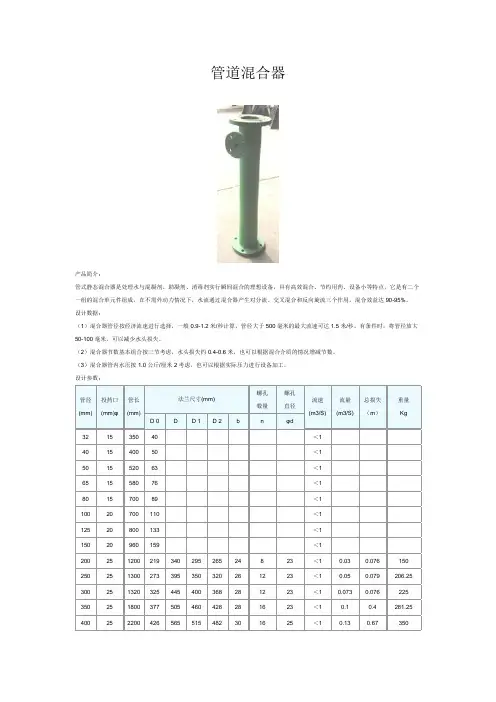
管道混合器产品简介:管式静态混合器是处理水与混凝剂、助凝剂、消毒剂实行瞬间混合的理想设备,具有高效混合、节约用药、设备小等特点,它是有二个一组的混合单元件组成,在不需外动力情况下,水流通过混合器产生对分流、交叉混合和反向旋流三个作用,混合效益达90-95%。
设计数据:(1)混合器管径按经济流速进行选择,一般0.9-1.2米/秒计算,管径大于500毫米的最大流速可达1.5米/秒。
有条件时,将管径放大50-100毫米,可以减少水头损失。
(2)混合器节数基本组合按三节考虑,水头损失约0.4-0.6米,也可以根据混合介质的情况增减节数。
(3)混合器管内水压按1.0公斤/厘米2考虑,也可以根据实际压力进行设备加工。
设计参数:管径(mm) 投药口(mm)φ管长(mm)法兰尺寸(mm)螺孔数量螺孔直径流速(m3/S)流量(m3/S)总损失(m)重量KgD 0 D D 1 D 2 b n φd32 15 350 40 <140 15 400 50 <150 15 520 63 <165 15 580 76 <180 15 700 89 <1100 20 700 110 <1125 20 800 133 <1150 20 960 159 <1200 25 1200 219 340 295 265 24 8 23 <1 0.03 0.076 150 250 25 1300 273 395 350 320 26 12 23 <1 0.05 0.079 206.25 300 25 1320 325 445 400 368 28 12 23 <1 0.073 0.076 225 350 25 1800 377 505 460 428 28 16 23 <1 0.1 0.4 281.25 400 25 2200 426 565 515 482 30 16 25 <1 0.13 0.67 350安装:(1)混合器安装不受方向限制,可以水平、垂直或其他组合方式。

管道静态混合器SV型
技
术
资
料
管道静态混合器SV 型
产品概述:
静态混合器是一种没有运动部件的高效混合设备。
除了在石油炼制、化工行业被广泛应用外,
在医药、食品、矿冶、塑料挤出和环保等部门也被广泛应用。
与搅拌器、胶体磨、均质机、文氏管等传统的混合设备相比,具有流程简单,结构紧凑、能耗小、投资少、操作弹性大、不用维修、混合性能好等优点。
凡涉及到液—液,液—气,液—固,气—气的混合,乳化,中和,吸收,萃取,反应和强化传热等过程,都可以替代传统的相关设备。
性能说明:
型号
产品用途
技术性能
SV
适用于粘度≤102厘泊的液~液、液~气、气~气的混合乳化、反应、吸收、萃取、强化传热过程。
dh≤3.5适用于粘度≤102厘泊清洁介质。
dh≥5应用介质可伴有少量非粘性杂质。
最高分散程度1~2μm,液~
液相 不均匀度系数≤1~5%
更多资料请访问旗达官网(在百度上搜索‘湖北旗达’点击进入即可)
湖北旗达石化设备有限公司
技术部。
Color Touch-Screen Interface The color touch-screen LCD interface allows you to quickly check the status of the unit and identify problems. The controls of the Liebert STS2 are intuitive and simple. The color LCD monitor is divided into three segments. In addition to a system mimic diagram, there is a Status/Alarm panel and a section dedicated to operator instructions and menus. The screen allows you to configure the unit, including the control of the preferred source, auto/manual retransfer selection, alarm notification and other system setpoints. You benefit from improved operator effectiveness, reduced training time, and less chance of operator error.For maximum availability applications, the Liebert Static Transfer Switch2 (STS2) provides an automatic, seamless transfer between your critical load and the outputs of two independent UPS systems in a dual-bus power configuration. If the primary UPS should fail, the switch will automatically transfer the loads to the alternate UPS.Liebert is the market leader in dual-bus power systems, building the world’s most reliable UPS and Static Transfer Switch products. Liebert STS2 further extends our market leadership with design benefits unmatched by competitive products.2Standard features of theLiebert STS2 provide greateroverall protectionReliabilityy y 100% rated, fuseless design.y y Hot-swappable circuit breakers.y y Flash memory enables firmwareupdates while supportingcritical load.y y Rack-out control/powerassembly on units up to 600A toallow maintenance, service or fullreplacement without disruptingthe critical load.Flexibilityy y Internal CANBUS protocol:high-bandwidth communicationbetween system componentsvia twisted-pair cables. Optionscan be added as simplenetwork nodes.y y Dual-lug installation bus withpem nuts for single-handinstallation and “hot”torque service.Low Total Cost Of Ownershipy y Conservative design marginsand excellent overload capacity.y y UL listed.The Power to Protect Your Critical OperationsTrue Front-Access DesignAll mechanical and electronic components of the Liebert STS2 are accessible from the front of the unit for installation and service—no side or rear access required.This gives you several immediate benefits:y y Greater freedom in system design. The Liebert STS2 can be placed adjacent to or in back of other equipment. It can also be placed against a wall or partition.y y Simplified installation, with ample space for cable connections through top and bottom access plates.y y Less floor space required for maintenance access.y y Designed for maintainability, with all key components visible and accessible from thefront of the unit, without shutting down the connected load.34Figures 1 and 2Show results for the standard STS2 vs.the optimized STS2 for the samecondition (alternate source lags 120degrees) respectively. The optimizedtransfer control algorithm minimizesthe transformer saturation currentresulting from an out of phase transfer.Liebert® offers a patented optimized transfer option for the Liebert STS2 that greatly improves operation when used in primary side switching applications.The Liebert STS2 can be used in two different types of high-availability dual bus configurations—as primary or secondary side switches. For primary side switching, the unit is connected to the primary or input of a downstream transformer. On secondary side switching the Liebert STS2 is connected to the secondary or output of two transformers. One of the main advantages of using primary side switching is lower cost. These savings are the result of only one power distribution unit, a lower current due to 480V vs. 208V, and lower installation and wiring cost thanks to use of smaller three wire cable. The one drawback of this configuration is the creation of transformer inrush saturation current each time switching occurs. The downstream transformer can cause large peak saturation current during automatic transfers. The transformer saturation is caused byDC-flux built-up during transfer, especially when the sources are not in phase.Figure 1 Standard STS2 transfer Optimized Transfer Option Enhances Cost-Efficient System Operation See alsoWhite Paper: “Using an OptimizedTransfer Approach” (April 2014) at/en-US/pages/default.aspx5Liebert’s transfer control does more than balance the flux.Due to our unique approach to the optimized transfer algorithm, transfer time should not be the only performance measure for this new optimized switch. Liebert’s method, whenever possible, also seeks to minimize voltage disturbances while maintaining transformer flux balance. It takes both voltage disturbance and volt-second balance into consideration.Liebert has a unique flux balance algorithm that doesn’t just “sit and wait” for the balance point to occur. Rather, we will “pulse fire” the SCRs as soon as possible in order to minimize the load discontinuity and hence the voltage disruption.So how safe is this new optimized Liebert STS2 for your critical loads?The optimized Liebert STS2 safely meets both the CBEMA standard (prior to 1996) and the latest ITIC standard (1996) for critical loads. Liebert’s optimized STS2 minimizes the risk of transformer saturation problems during automatic transfers, while itsalgorithm control ensures minimumvoltage disturbance during transfers whilestill balancing the flux.The patented Liebert® static switch optimized transfer control algorithm significantly reduces the downstream transformer inrush saturation.The Liebert algorithm is designed to optimize transfer timing such that the volt-seconds applied to the downstream transformer primary is balanced, thusminimizing peak saturation current. This balance is achieved by directly computing the volt-second applied to the transformer during transfer events and determining the optimum time to turn on the alternate source SCRs in order to balance the volt-second within specified tolerance.This results in a volt-second balancing algorithm that is independent of voltage wave shape, voltage failure decay rate, etc., making it superior to otheralgorithms based on voltage phase angle difference only.Figure 2 Optimized STS transfer6with hinged doors to allow for easy access. The cabinet contains one vertically mounted I-line panelboard for load distribution. The panelboard is totally enclosed with an accent cover that provides access without exposing other portions of the unit. The panelboard provides space for 100A through 250A three-pole branch circuit breakers. It also includes a separate isolated neutral bus bar and safety-ground bus bar for the neutral and safety-ground connections.Redundant Output Breaker: An output plug-in, non-automatic circuit breaker provides redundancy in the output power path. The breaker is connected in parallel with the output plug-in non-automatic circuit breaker.Input Junction Boxes and Cable (Up to 600A): The input junction box option is available to simplify input connections to the STS2. Two input junction boxes and the associated flexible 10-foot long input cables are provided with this option. Available with bottom cable entrance only, typically when the unit is located on a raised floor.Remote Source Selection: An optional Remote Source Selection board may be installed in your STS2. This option allows you choose the preferred input source from a remote location. Terminal connections enable you to remotely select a preferred source in the same process as the local source transfer selection. Key Lockout Switch: The key lockout switch activates a software lockout of the touch-screen display to prevent manual transfers and configuration changes. When locked out, the touch-screen becomes a read only display. A key is needed to perform manual transfers or change settings.Liebert® STS2 Communication and Product OptionsLiebert STS2 has a wide choiceof monitoring and communicationsoptions to keep you connectedto your critical powerprotection system.RS-232 Terminal Port: Standard on allunits, this port is primarily used as analternate user interface to configure,control, and diagnose the system.Input Contact Isolator (ICI) Board:Customizable input relays allow alarmsfrom other devices to be displayed onLiebert STS2 display. Provides aninterface for up to eight user inputs.External messages and alarms can berouted to the unit, via the ICI.Programmable Relay Board (PRB):Programmable output relays for customcustomer alarms and connections. Upto two PRBs can be installed in theLiebert STS2 to route system eventsto external devices.Comms Board: This board provides adirect connection to a Liebert SiteScan®Web system, via an RS-422. SiteLink-12 orSiteLink-4 is required for SiteScan tocommunicate with the Liebert STS2.Options and AccessoriesSeismic Anchors: To ensure stability forthe unit in the event of seismic activity,anchors are available for securing the unitto a concrete floor to meet seismicZone 4 requirements.Seismic Floor Stand: Designed to levelthe unit and provide bottom cablingaccess without relying upon a raised floorfor support. Available in 18, 24,30, 36 inch heights.Distribution Cabinet (Up to 600A): Anoutput distribution cabinet mounts on the side of the STS2. It is a full height sectionLiebert IntelliSlot™ 485 Web Card ADPT y y Allows systems to be viewed from the network using a web browser. y y Delivers SNMP, Telnet and web management. y y Provides security using HTTPS message encryption. y y Supports 10 and 100 MBit Ethernet for legacy and modern networks.y y Provides compatibility with Liebert MultiLink shutdown software, to prevent data loss and ensure data availability. y y Supports Liebert SiteScan WEB enterprise monitoring software, to provide trending for proactive analysis and maintenance to ensure facility uptime. y y Interfaces to Liebert Nform alarm notification software, to facilitate quick corrective action. Liebert IntelliSlot 485 Web Card ADPT provides connectivity to any TCP/IP-based Ethernet network to allow the device to communicate with network management systems (NMS) via SNMP. Events can be transmitted to the NMS to provide remote status monitoring, plus fault and alarm detection. The card includes an RJ-45 port for an Ethernet connection, via Category 5 cable. The card can also integrate the system with an existing Building Management System (BMS) or out-of-band monitoring,using Modbus.Specifications(KW)(inches)(mm)(lbs)(kg)(inches)(mm)(lbs)(kg)1000.830x32x77762x813x1956780 35448x44x821016x1194x2082880399250 1.3730x32x77762x813x195678035448x44x821016x1194x2082880399400 2.0438x32x77965x813x1956120054448x44x821016x1194x20821300590600 3.0838x32x77965x813x1956120054448x44x821016x1194x20821300590800 4.0384x32x772134x813x19562500113492x53x822337x1346x2082260011791000 5.0984x32x772134x813x19562500113492x53x822337x1346x208226001179Note: ¹Shipping dimensions and weight include the pallet and packing material. Actual weights will vary depending on installed options.7Continuous 24-hour remote monitoring of UPS/power conditioning equipment, environmental products and other critical space support systems is available. No matter where your facilities are located, we can provide continuous oversight of a wide range of critical installations from our Customer Response Center. When a problem is detected, the monitoring system immediately alerts the Customer Response Center where each alarm is evaluated and processed. The center offers instant phone assistance using a customer-defined response and call escalation plan. Liebert will coordinate all service vendors, track the response and solution time for service calls and provide comprehensive reports on alarms and corrective actions.schematics and your equipment’s complete service record from the time it was started up.Remote Monitoring — Always There, Always Alert The key to providing proper service for your critical power systems is being aware of that equipment’s operating status atany given time. For customers who need to have these vital protection systems continuously monitored, but don’t want to do it themselves, Vertiv Service offers Remote Monitoring Service. This seamless, rapid-response system is designed to maximize the capabilities of your Liebert equipment by maximizing the effectiveness of its monitoring capabilities.Critical Space Support from Vertiv™ ServiceTotal Service Capability Vertiv provides a Basic, Essential and Preferred level of maintenance and service that allows you to select the complement of critical power system services that best fits your requirements.These programs include guaranteed four-hour response time, emergency service and preventive maintenance. With more than 300 Liebert-employed Customer Engineers and a network of over 900 factory authorized service personnel, our technical capabilities, geographical coverage and ability to respond are second to none. These factory-trained service professionals have direct access to the most comprehensive factory authorized parts network in the industry. We also provide them withimmediate online access to detailedOperating SpecificationsVoltage: 208, 220, 240, 380, 400, 415, 480 or 600 VAC (field selectable), +/- 10%Frequency: 50 or 60 Hz (field selectable), +/- 0.5 HzOverload Capability: 125% for 10 minutes,150% for 2 minutesOperating Temperature: 0 to 40° C。
JY型管式静态混合器一、适用范围管式静态混合器,是净水厂、污水厂及工业用水、废水处理设备中投加混凝剂、助凝剂、消毒剂后与水流实现瞬时混合的新颖设备,适用于生活饮用水、城市自来水厂。
二、结构特点管式静态混合器整件均为钢制结构,具有坚固耐用、结构简单、不需专门占用场地、安装容易、投资少、使用寿命长、混合效率高等特点,在运行过程中五任何有害物质溶析出。
三、工作原理管式静态混合器主体在混合管内设一系列特殊设计的螺旋状混合单体,每两个相邻的形状相同的单体,方向相反地交叉固定在管道内,运行中单体本身不发生旋转运动,混合器内也无任何转动部件,而是以流水的动能作为混合的能量,流体在混合单体内流动时,每一单体将水流一分为二,混合器的总分流数将按单体的数量成几何级数逐增,这种混合作用称为成对分流混合,而由于相邻的混合单体方向相反,使水流不断产生方向相反的漩涡和反漩涡,这种漩涡和反漩涡更增强了混合效率,在混合器内同时发生三种混合作用,从而使得本体具有传质速度快,能完成不同液体介质在瞬时内有效混合的特点。
、四、技术性能1、混合器公直径D150--D1200mm2、混合单体与管中心线夹角26°30′3、混合单体个数一般为三个亦可根据混合效率的不同要求而增减4、混合单体板在管中心线方向上的投影长度:D/LX=1:15、设计流速V,由设计人(用户)选用,一般为:DN≥DN6、混合效率:一般为90%以上五、外形及尺寸安装1、外形尺寸附表、附图2、安装(1)静态混合器一般宜水平安装,在条件不许可时也可采用垂直或倾斜安装,水平安装时一般宜按设于矩形井室内。
(2)管式静态混合器的安装位置应尽可能接近反映池或者微絮凝接触过滤池的进口处,可将药加在前端管中用计量泵或其他方法加入加药后的水流通过混合器后直接进入反应池或接触过滤池。
(3)为便于检修在混合器的两端宜安装闸阀,并在后端设有一个活接头,以便安装和拆卸。
(4)安装示意图见附图。
mixpac静态混合管规格(原创实用版)目录1.引言2.mixpac 静态混合管的定义和作用3.mixpac 静态混合管的规格参数4.mixpac 静态混合管的应用领域5.结论正文【引言】在现代科技领域,混合技术的应用越来越广泛,尤其是在化学、生物和环境科学等领域。
为了满足这些领域对于混合技术的高要求,mixpac 静态混合管应运而生。
本文将为您详细介绍 mixpac 静态混合管的规格参数及其应用领域。
【mixpac 静态混合管的定义和作用】mixpac 静态混合管是一种可以将两种或多种流体在管道内静态混合的设备。
与传统的动态混合设备相比,静态混合管具有混合效果好、能耗低、操作简便等优点。
其主要作用是在微流控领域实现精确、高效的混合,为科研和工业生产提供可靠的技术支持。
【mixpac 静态混合管的规格参数】mixpac 静态混合管的规格参数主要包括以下几个方面:1.管材:混合管通常采用不锈钢、玻璃或聚合物等材质制成,以满足不同应用场景的需求。
2.管径:混合管的管径范围较广,从几毫米到几十毫米不等。
管径的选择应根据实际流量和混合效果来确定。
3.混合长度:混合管的长度也会影响混合效果,一般而言,混合管越长,混合效果越好,但也会增加流体的阻力。
4.接口形式:混合管的接口形式多样,有螺纹连接、焊接连接、卡套连接等,以满足各种连接需求。
5.工作压力:混合管的工作压力应根据实际应用场景选择,一般在0.1MPa 至 1.0MPa 之间。
6.流量范围:混合管的流量范围较广,一般可以从几毫升/分钟到几千毫升/分钟。
流量的选择应根据实际需求来确定。
【mixpac 静态混合管的应用领域】mixpac 静态混合管广泛应用于以下领域:1.化学领域:在化学合成、分析检测等方面,静态混合管可以实现精确的样品制备和试剂配制。
2.生物领域:在生物医药、生物技术等领域,静态混合管可用于实现生物分子的精确混合,从而提高实验的准确性和可靠性。
静态管道混合器技术说明
(一)供货范围
本公司提供GJH型管道静态混合器为成套设备,整套装置包括如下:
筒体、法兰、混合单体及加药口等;
此外配备基础螺栓等安全和有效运行所必须的附件及工具。
(二)概述及工作原理
本管道混合器按照JB2932-86“水处理设备制造技术条件”标准及招标文件要求尺寸进行设计和制造。
管道混合器利用法兰安装在沉淀池的进水管路上,加药管和混凝加药装置连接。
在工作时,水流通过混合器产生分流、交叉混合和反向旋流三个作用,使从加药管进入的药液,能迅速均匀地扩散于整个水体,达到瞬间快速混合的目的,并使水中的悬浮物质能迅速混凝。
(三)主要结构部件说明
管道静态混合器主要由筒体、混合单体、法兰和加药管等部件组成。
1.筒体及混合单体
筒体材料采用不锈钢板卷制而成,筒体内设有三节混合单体,则其中两个左螺旋单体分别设于两端,一个右螺旋单体设于中间;若筒体中设有两节混合单体,则其中左、右两个螺旋单体分别设于两;单体叶片形状为四分之一椭圆,与筒体焊接后,其弧形面与筒体内壁相吻合。
2.加药管
混合器筒体表面上设有4只加药口,并列于同一水平线上;加药管采用不锈
钢材料制成,并伸入筒体内部,并可以调节伸入的深度,其调节幅度大于150mm,加药管顶端可伸入管道内1/30处,即提高混合效果,又不使口子腐蚀;加药管与筒体的接口采用法兰安装,因而接口处不会渗漏。
(四)设备安装
本设备安装时整体吊装,法兰一端和沉淀池进口处连,另一端和进水管法兰连接,安装精度符合管道安装要求,其底部回填土应夯实,如果土质疏松,应在底部填充碎砂石或制作管道支撑,以防止底部土质下沉。
加药口和加药管联接,混凝剂通过加药装置、加药管进入接口,进入加药点,其加药点应在混合器管的中心位置附近,在投产调试时,根据药剂混合效果可适当调节其位置。