Lesson 4 Thermal Storage 热存储
- 格式:ppt
- 大小:1.62 MB
- 文档页数:16
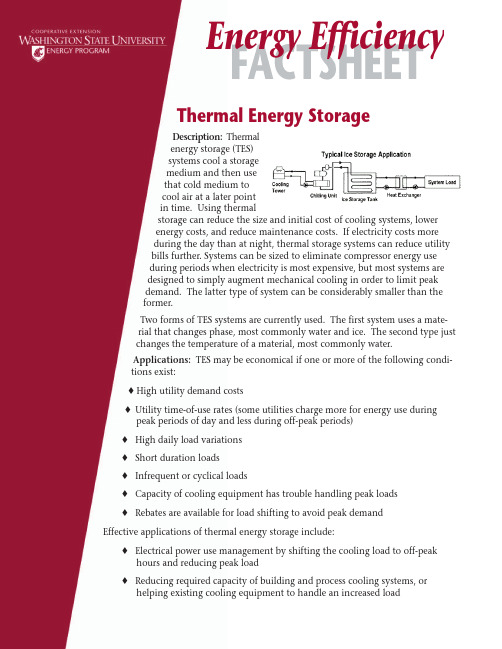
Thermal Energy StorageDescription:Thermalenergy storage (TES)systems cool a storagemedium and then usethat cold medium tocool air at a later pointin time. Using thermalstorage can reduce the size and initial cost of cooling systems, lowerenergy costs, and reduce maintenance costs. If electricity costs moreduring the day than at night, thermal storage systems can reduce utilitybills further. Systems can be sized to eliminate compressor energy useduring periods when electricity is most expensive, but most systems aredesigned to simply augment mechanical cooling in order to limit peakdemand. The latter type of system can be considerably smaller than theformer.Two forms of TES systems are currently used. The first system uses a mate-rial that changes phase, most commonly water and ice. The second type justchanges the temperature of a material, most commonly water.Applications:TES may be economical if one or more of the following condi-tions exist:♦ High utility demand costs♦ Utility time-of-use rates (some utilities charge more for energy use duringpeak periods of day and less during off-peak periods)♦ High daily load variations♦ Short duration loads♦ Infrequent or cyclical loads♦ Capacity of cooling equipment has trouble handling peak loads♦ Rebates are available for load shifting to avoid peak demandEffective applications of thermal energy storage include:♦ Electrical power use management by shifting the cooling load to off-peakhours and reducing peak load♦ Reducing required capacity of building and process cooling systems, or helping existing cooling equipment to handle an increased loadEnergy EfficiencyWater storage systems are often used in new large cooling system applications in conjunction with cogeneration and/or district energy systems. Water-ice storage is the most common cooling storage in smaller applications. Because latent heat storage (phase change between water and ice) has a smaller volume, it is often chosen for retrofit applications with limited space.In general, the buildings that offer the highest potential are offices, retail, and medical facilities. The Dallas Veterans Affairs Medical Center installed a 24,628 ton-hours chilled water TES that resulted in a reduction in demand of 2,934 kW and a reduction in annual electricity cost of $223,650. The local utility provided $500,000 of the total cost of $2.2 million required for design and installation. Savings resulting from installation of the thermal storage technology will allow the VA to recoup its investment within 7 years.Performance/Costs:Thermal energy storage systems are installed for two major reasons: lower initial project costs and lower operating costs. Initial cost may be lower because distribution tem-peratures are lower and equipment and pipe sizes can be reduced. Operating costs may be lower due to smaller compressors and pumps as well as reduced time-of-day or peak demand utility costs. The economics of thermal storage is very site- and system-specific. A feasibility study is generally required to determine the optimum design for a specific application. Several examples exist of effective TES systems that were installed for less cost than conventional alternatives and that also provided significant energy and energy cost reductions.TES projects often profit from unexpected benefits that are secondary to the primary reason for an action. For example, a well designed TES air conditioning application may experience reduced chiller energy consumption, lower pump horsepower, smaller pipes, high reliability, better system balancing and control, and lower maintenance costs.Determining electrical cost savings from shifting chiller operation from daytime to night-time (oroff-peak operation) can be complicated, depending upon the local utility rate structure. Your utilitymay have time-of-day peak rates as well as differing peak demand rates. Without thermal storage, a chiller will typically operate during times of peak electrical demand, and thus be included in thepeak monthly demand charge. Your greatest savings will occur when you shift chiller operation tooff-peak times.Table 1 shows the benefit of using thermal storage to shift chiller use to a time when the rest of the facility is unoccupied. The chiller load (in terms of ton-hours delivered) is the same, but demand charges for the chiller would be eliminated. The table shows the effect of two different utilitydemand rates ($6 and $12 per kW).Availability:Thermal energy storage equipment and installations are available from a number of suppliers. For a list of equipment manufacturers, contact the Thermal Storage Applications Re-search Center (TSARC) or go to the Energy User News Buyers Guide website (see “For Additional Information” below).For Additional Information:Heating, Ventilating, Air Conditioning, and Refrigerating Center and Thermal Storage Appli-cations Research Center (TSARC)These centers, located at the University of Wisconsin, perform research to develop technologies that increase the efficiency of systems, and offer technical assistance and education to industry./centers/tsarc/tsarc.htmlEnergy User News Buyers GuideThis list of manufacturers can be searched by technology type, e.g. search for Thermal Energy Storage./buyers.htmThermal storage and deregulationFrom a paper published in the April 1998 ASHRAE Journal/main/whitepapers/tsdereg.htmBenefits and savings of chiller replacement & various thermal storage projectsU.S. Army case studies/ul/gascool/storage.htmThermal Energy Storage at a Federal FacilityDescribes the benefits of a project in which the Dallas Veterans Administration Medical Center and Texas Utilities Electric Company join in an unprecedented partnership to lower energy costs./femp/financing/fed_facility_439.htmlIce Storage Retrofit for Rooftop Air ConditioningFederal Energy Management Program (FEMP) New Technology Demonstration Program evaluatesice storage retrofit for rooftop air conditioning./femp/prodtech/icesum.html© 2003 Washington State University CooperativeExtension Energy Program. This publicationcontains material written and produced for publicdistribution. You may reprint this written material,provided you do not use it to endorse a commercialproduct. Please reference by title and creditWashington State University Cooperative Extension。
Thermo-Chemical Heat Storage using theReversible Calcium Hydroxide/Calcium Oxide System Franziska Schaube, Antje Wörner, Rainer TammeGerman Aerospace (DLR), Stuttgart, GermanyIntroductionHigh temperature heat storage systems are crucial to improve energy efficiency of power plants and the use of process heat. They are required for permanent energy supply in solar thermal applications. Thermo-chemical reactions offer an option for thermal storage at temperatures where common sensible or phase change materials are not available. Because of their high energy density and low material cost reversible gas-solid reactions are highly promising candidates. In this work a thermo-chemical storage based on the reversible reaction “Ca(OH)2↔CaO+H 2O” has been investigated which can achieve storage densities above 300 kWh/m 3 operating in a temperature range between 400 and 650°C.ResultsReversibility and cycling stability has been proven experimentally by thermogravimetric measurements. Also, kinetic parameters and thermal conductivity of commercially available powder have been experimentally determined. Different reactor concepts with direct or indirect contact of the heat transfer fluid with the solid or gaseous reactants have been discussed with respect to limiting effects of the reaction rate and heat transport. A 2D-model solved by the Finite Element Method has been developed to describe heat and mass transfer in a packed bed reactor during the reactions. The reactor concept with direct heat transfer by flowing the gaseous reactant plus additional inert gas through the solid reactants did not show any limitation due to heat transfer. If reaction kinetics are fast enough reactor performance is rather limited by the thermal capacity of the gaseous heat transfer fluid to take-up heat of reaction. Experimental proof of the direct contact reactor concept has been successfully provided in laboratory scale. Results of parametric studies of mass flow, temperature, pressure and partial pressure are presented which show promising performance with regard to reaction rate, temperature level and reversibility. 热化学热存储使用可逆氢氧化钙/氧化钙体系讨论了关于的影响反应速率和热传输限制因素质量流量、温度、压力和部分压力反应速率、温度水平和可逆性。

新型储能定义和分类
储能是指将能量在可控条件下存储起来,以备将来使用的技术和过程。
随着能源需求和可再生能源的增加,发展新型储能技术成为提高能源系统灵活性、可靠性和可持续性的关键。
新型储能可以按照不同的原理和储能介质进行分类,以下是几种常见的分类方式:
电化学储能(Electrochemical Energy Storage):通过将能量以化学形式存储在电化学电池中,在需要时通过化学反应释放能量。
例如,锂离子电池、铅酸电池和燃料电池等都属于电化学储能技术。
机械储能(Mechanical Energy Storage):将能量以机械形式存储,通过运动、物体位置或压缩气体等方式存储和释放能量。
例如,压缩空气储能(CAES)、液压储能和弹簧储能等都属于机械储能技术。
热储能(Thermal Energy Storage):将能量以热的形式存储,利用相变、化学反应或热惯性等原理储存和释放热能。
例如,蓄热式太阳能热水器、熔盐储热系统和热蓄堆等都是热储能技术的例子。
电动力学储能(Electromagnetic Energy Storage):通过电磁力的存储和释放来实现能量储存。
例如,电容器和超导磁体都属于电动力学储能技术。
化学储能(Chemical Energy Storage):将能量以化学键的形式存储,通过化学反应释放能量。
例如,氢气和天然气等化学反应储能技术。
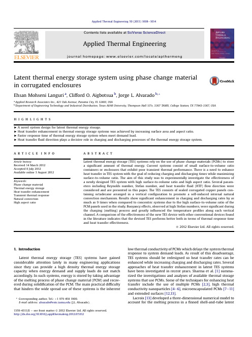
Latent thermal energy storage system using phase change material in corrugated enclosuresEhsan Mohseni Languri a ,Clifford O.Aigbotsua b ,Jorge L.Alvarado b ,*a Applied Research Associates Inc.,421Oak Avenue,Panama City,FL 32401,USAbDepartment of Engineering Technology and Industrial Distribution,Texas A&M University,Thompson Hall 117e,3367TAMU,College Station,TX 77843-3367,USAh i g h l i g h t s<A novel system design for latent thermal energy storage.<Heat transfer enhancement in thermal energy storage systems was achieved by increasing surface area and aspect ratio.<Faster response time of thermal energy storage system when meet demand load.<Heat transfer fluid direction plays a decisive role in charging and discharging processes of the thermal energy storage system.a r t i c l e i n f oArticle history:Received 14March 2012Accepted 8July 2012Available online 3August 2012Keywords:Phase change material Thermal energy storage Heat transfer enhancement Transient thermal response Natural convection High aspect ratioa b s t r a c tLatent thermal energy storage (TES)systems rely on the use of phase change materials (PCMs)to store a signi ficant amount of thermal energy.Current systems consist of small surface-to-volume ratio containers or enclosures that exhibit poor transient thermal performance.There is a need to enhance heat transfer in TES system with the goal of reducing charging and discharging times while maximizing surface-to-volume ratio.The aim of this study was to experimentally investigate the effectiveness of a newly designed TES system with high surface-to-volume ratio and high aspect ratio.Several param-eters including Reynolds number,Stefan number,and heat transfer fluid (HTF)flow direction were considered and are presented in this paper.The TES consists of sealed corrugated copper panels con-taining octadecane arranged in a vertical con figuration to promote a self-induced internal natural convection mechanism.Results show signi ficant enhancement in charging and discharging rates by as much as 9times when compared to concentric systems due to the high surface-to-volume ratio of the PCM panels used in the study.Buoyancy effects,observed at high Stefan numbers,were signi ficant during the charging (melting)process and greatly in fluenced the temperature pro files along each vertical channel.A comparison of the effectiveness of the new TES device with other conventional devices found in the literature indicates that the devised TES performs better both in terms of thermal response time and heat transfer effectiveness.Ó2012Elsevier Ltd.All rights reserved.1.IntroductionLatent thermal energy storage (TES)systems have gained considerable attention lately in many engineering applications since they can provide a high density thermal energy storage capacity when energy demand and supply loads do not match accordingly.In such systems,energy is stored by taking advantage of the melting process of phase change material (PCM)and recov-ered during solidi fication of the PCM.The main practical dif ficulty that hinders the wide spread use of these systems is the inherentlow thermal conductivity of PCMs which delays the system thermal response to system demand loads.As result of this disadvantage,TES systems should be redesigned so heat transfer rates can be enhanced while increasing charging and discharging rates.Several approaches of heat transfer enhancement in latent TES systems have been investigated in recent years.Sharma et al.[1]summa-rized the investigations and analyses of available thermal storage systems that use PCMs.Some of the techniques for enhancing heat transfer include the use of multiple PCMs [2,3],high thermal conductivity nanoparticles [4e 6],microencapsulated PCMs [7e 11]and extended surfaces [12,13].Lacroix [13]developed a three-dimensional numerical model to account for the melting process in a finned shell-and-tube latent*Corresponding author.Tel.:þ19794581900.E-mail address:alvarado@ (J.L.Alvarado).Contents lists available at SciVerse ScienceDirectApplied Thermal Engineeringjournal ho mep age:www.elsevi/locate/apthermeng1359-4311/$e see front matter Ó2012Elsevier Ltd.All rights reserved./10.1016/j.applthermaleng.2012.07.012Applied Thermal Engineering 50(2013)1008e 1014heat thermal storage(LHTS)system with the PCM located on shell side and the heat transferfluidflowing through the core of it. Lacroix[13]accounted for natural convection using an effective thermal conductivity term as a function of Rayleigh number in the governing croix[13]concluded that a large amount of heat was conducted through thefins in the radial direction which increased the heat transfer rate of the system.Zhang and Faghri[14]numerically studied the latent thermal energy storage configuration used by Lacroix[13].They modeled afinned tube placed in the PCM with heat transferfluidflowing through it.They considered the effect of externalfin height on heat transfer.It has been shown that the liquid fraction of PCM at anytime during melting could be increased by increasing the externalfin height.They also focused on the effect of initial sub-cooling on the location of the melt front and liquid fraction.They proved that the height of the externalfins has a significant effect on the melting fronts surrounding eachfin but has minimal effect on the region of PCM located betweenfins.The results of the study showed that the moving volume fraction(MVF)significantly increased by increasing the heights of thefins.Seeniraj et al.[15]numerically investigated the transient behavior of high temperature PCMs stored in an externally-finned tube in a shell latent heat storage module.They used few annular thinfins at specific locations.Tubes were made of high thermal conductivity materials.Their models take into account the axial and radial temperature variations both in tube wall andfins, respectively.They showed that the performance of the unit can be appreciably enhanced by increasing the number offins for a given set of geometrical parameters.Recently,other researchers have attempted to improve the heat transfer rate during charging and discharging of TES systems using an optimized design configuration[16,17].Agyenim et al.[16] designed a horizontal multi-tube heat storage system and compared its performance to that of a control system comprising of a single heat transfer tube at the center of the TES system.They observed that phase change in the multi-tube system was domi-nated mainly by convective heat transfer than by conduction heat transfer as seen in the control system.The authors also reported that the temperature gradients recorded within the PCM in the radial direction of the multi-tube were steeper than in the control system.Akgun et al.[17]designed and constructed a tube-and-shell heat storage system in which the paraffin wasfilled in the annular space between a tube and a concentrically placed conical outer shell.They observed that the storage geometry with a shell angle of 5 resulted in approximately a30%decrease in the total melting time compared to shell tilt angle of0 ,which could be attributed to the effect of secondaryflows that take effect at an angle of5 .The objective of this paper is to elucidate the effects of using a high aspect ratio with high surface-to-volume ratio TES system. The new TES designed consists of long corrugated panels which have an inverted configuration compared to conventional TES system.Experimental results indicate that the new TES design results in larger heat transfer rates,and lower charging and dis-charging times.The heat transferfluidflows in the inverted TES system around the PCM panels or enclosures.2.Experimental setup and procedure2.1.Experimental setupA vertical thermal energy storage(TES)system with consid-erably large surface-to-volume ratio(506.5mÀ1per panel)and high aspect ratio(length/width¼6.35)was designed and man-ufactured as explained below.The designed TES unit consists of total of six30.5cm long corrugated panels joined axially at angles of60 with respect to the TES center as shown in Fig.1a.Each panel was made of copper sheets shaped into square channels as illustrated in Fig.1b.Each panel consists of six square-type sections with sides of0.8cm,and a center to center distance of 1.6cm.The panels were soldered together to make the whole system water tight.To determine the effectiveness and thermal response of the designed TES system,an array of type T thermocouples was placed inside the TES system as shown in Fig.1c.Due to symmetry of the TES with respect to its central axis,panel1was used for temper-ature monitoring only and panel4(on the opposite side)was used for verifying the symmetry assumption as shown in Fig.1a.A ceramic-type epoxy was used to seal the holes created when the thermocouples were inserted into the panels.The thermocouple wires were T-type(TT-T-30-SLE)from Omega,which were thin enough(gauge30)to avoid the thermocouplefin effect.The ther-mocouples were also insulated with PFA(fluorocarbon polymer) which exhibits very low thermal conductivity.Furthermore,addi-tional insulation was applied on all thermocouples using plastic heat shrink tubes to reduce any possible conduction effects through each thermocouple wire.The thermocouple accuracy of this classof Fig.1.(a)3D schematic view of TES,(b)cross-section of TES panel and,(c)side view of PCM enclosures4(left side)and1(right side)showing thermocouple positions.nguri et al./Applied Thermal Engineering50(2013)1008e10141009thermocouples was less than Æ0.5 C.All thermocouples were calibrated based on the manufacturer guidelines,and corrections factors,uncertainty and error propagation analysis for each thermocouple were calculated and performed as indicated in reference [12].A volume of 150cm 3of liquid octadecane was poured into each PCM panel.The total volume of octadecane (PCM)in the whole TES system was 900cm 3(0.9l).The thermo-physical properties of octadecane are presented in Table 1.After the whole TES unit was assembled,the unit was placed inside a vertical clear plastic pipe.The heat transfer fluid was allowed to flow through the pipe either upwardly or downwardly and around the TES unit.Two identical perforated disks (16cm diameter)with an open area of 63%were placed at 15.2cm from both ends of the TES unit inside the clear pipe.These two fixed perorated disks were used to ensure fully developed flow (plug flow)inside the clear pipe before passing through the TES.The perforated plates allowed for the development of an isotropic fluid flow structure so the whole TES external surface could be exposed to a uniform velocity field.A schematic diagram of the whole experimental setup is shown in Fig.2.A water loop was connected to an insulated water tank that was used as a source of cold and hot water for charging and dis-charging the TES device.The tank had a temperature-controlled heater that was used to control the temperature of the heat transfer fluid.A variable speed Goulds pump (model G&L series)was used to pump water through the TES unit.A Flowmeter (Siemens FM Mag flo 5000)with an accuracy of 0.5%was used for flow measurements,and all thermocouple data were recorded every 10s using an Agilent 34978-A data acquisition unit,and analyzed using Benchlink data logger software.Two-way valves were used to control the direction of the heat transfer fluid (i.e.water)inside the clear pipe holding the TES unit.2.2.Experimental procedureA total of eight experiments were conducted taking into account flow direction,flowrate (i.e.Reynolds number of heat transfer fluid in the shell),inlet heat transfer fluid temperature (i.e.Stefan number)under charging and discharging conditions as shown in Table 2.Each experiment was repeated three times.Dimensionless numbers such as Reynolds (Eq.(1))and Stefan (Eq.(2))were used to classify and analyze the experimental resultswhere _mis mass flowrate through the system (kg/s),D H is the hydraulic diameter of TES (m),m is dynamic viscosity of the heat transfer fluid (N s m À2),T HTF and T m are inlet temperature of the heat transfer fluid and PCM melting temperature,respectively ( C),c is the speci fic heat (J kg À1K À1)and l is the latent heat of fusion of PCM (kJ/kg).Re ¼4_m p m D H(1)Ste ¼c ðT HTF ÀT m Þl(2)Flowrate and the inlet heat transfer fluid temperature were converted to Reynolds and Stefan number,respectively,using the dimensionless number de finitions shown above.The hydraulic diameter used in the Reynolds number calculations is de fined as Eq.(3):D H ¼4A¼4A shell ÀA panels shell þP panels(3)where A is the cross-sectional area and P is the wetted perimeter of the cross-section.The hydraulic diameter was finally calculated to be D H ¼4.3cm [12].Preceding each experiment,cold water at about 19 C was first circulated through a by-pass line (by adjusting the proper valves)to set the speci fic constant flowrate of the experiment.Setting different valves of the system appropriately allowed us to control flow direction.3.Results and discussionsSeveral heat transfer experiments were conducted to deter-mine the effects of heat transfer fluid direction (downward or upward)and temperature,and mass flowrate on heat transfer performance.3.1.Effect of flow direction on heat transfer enhancementThe effects of changing the HTF flow direction on the temper-ature pro file and heat transfer enhancement of the TES system were studied.For HTF flow in the upward direction,it is anticipated thatTable 1Thermo-physical properties of 99%octadecane [12].PropertyValue Unit Melting point,T m28CLatent heat of fusion,l PCM245kJ kg À1Thermal conductivity,liquid (k l )0.15W m À2K À1Thermal conductivity,solid (k s )0.42W m À2K À1Speci fic heat,liquid (c p,l ) 2.2kJ kg À1K À1Speci fic heat,solid (c p,s ) 1.8kJ kg À1K À1Density,liquid (r l )775kg m À3Density,Solid (r S )814kg m À3Fig.2.Schematic diagram of the setup.Table 2Details of experimental conditions.Experiment Q (m 3/s Â10À4)Reynolds no.T HTF ( C)Stefan no.Time (s)Flow direction 1Charging 4.0314,07032.00.029800Downward Discharging 21.3e 8002Charging 4.0314,07036.00.059800Downward Discharging 8.2528,80020.7e 8003Charging 1.54538532.30.029720Downward Discharging 15.0e 8004Charging 4.0314,07032.30.029250UpwardDischarging21.5e50nguri et al./Applied Thermal Engineering 50(2013)1008e 10141010internal buoyancy effects can enhance heat transfer compared to the downward fluid flow case.Since the PCM at the bottom of the TES experiences phase change first when the HTF flows upwardly,a signi ficant density gradient should set in,which results in a signi ficant buoyancy effect.Fig.3shows the temperature response along channel C when the HTF flows upwardly (Fig.3a)and downwardly (Fig.3b).As observed in Fig.3,the temperature depicts a similar trend;however,the amount of time needed for melting was less when the HTF flowed upwardly.With regards to charging time,all the positions along channel C attained the melting temperature of 28 C at about 1.0min when the HTF flowed upwardly,which represents about a 70%reduction in charging time when compared to the case where the HTF flowed downwardly.Fig.4depicts the effect of HTF flow direction during discharging process.As seen in Fig.4,HTF flow direction plays a signi ficant role in terms of discharging time.Moreover,it is evident from the plots that the discharging time is more than three times faster when the HTF flows upwardly.This can be directly attributed to solidi fication process of the phase change material (PCM)and where it occurs.In the downward HTF flow case,more PCM is solidi fied along the channel walls,while in the upward HTF flow case,solidi fication takes place first at or near the bottom of the channels.This in turn favors convection and conduction in the latter case,while conduction dominates in the former case,which can explain the signi ficant difference in discharging time.3.2.Effect of Stefan number on temperature pro file of PCMAs part of the characterization of the TES system,Stefan number as de fined in Section 2.2was used to understand the effect of heat transfer fluid temperature on heat transfer performance of the TES.Fig.5shows the effect of Stefan number on the melting process along channel C,where Stefan number for HTF temperatures at 32 C and 36 C were 0.029and 0.059,respectively.As shown in Fig.5b,higher Stefan number leads to a strati fication effect of the phase change material.The effect of external convection caused by the heat transfer fluid can be noticed in Fig.5b,where the lower side of the PCM channel undergoes phase change first even though the HTF was flowing downwardly.3.3.Effect of HTF mass flowrate on TES performanceAxial and radial temperature gradients of the latent heat storage (TES)system during the charging process were recorded at two different mass flowrates as shown in Fig.6a and 6b.Axial and radial temperature gradients (d T /d x or D T /D x )were calculated by using temperature data along the C channel and row 2,respectively.It is worth noting that increasing the flowrate by a factor of two,does not affect the axial temperature gradient signi ficantly as seen in Fig.6a.This is indicative that the heat transfer process inside the PCM channel along the vertical direction is mainly affected by internal convection and conduction.Fig.6b shows that flowrate does have a signi ficant effect on the radial temperature gradient.This is expected since the amount of HTF interacting with the TES system increases with radial distance.Moreover,the overall radial distribution of PCM decreaseswithFig. 3.Effect of the fluid flow direction during charging on temperature pro file Re ¼14,070,Ste ¼0.029and T HTF ¼32 C,(a)upward (Experiment 4)and (b)downward (Experiment 1).20222426283001234T e m p e r a t u r e(C )Time (minutes)2022242628303691215T e m p e r a t u r e (C )Time (minutes)abFig.4.Effect of the fluid flow direction during discharging on temperature pro file Re ¼14,070,Ste ¼0.029and T HTF ¼21 C,(a)upward (Experiment 4)and (b)downward (Experiment 1).nguri et al./Applied Thermal Engineering 50(2013)1008e 10141011radial distance.Furthermore,lower HTF flowrate results in decreasing temperature gradients with time.parison of present system with previous studyIn order to compare our experimental results with previous work,Experiment 3was designed and run for this purpose.Esti-mated experimental conditions similar to those used by Agyenim et al.[16]were applied to the devised TES in order to make a fair comparison between its performance and that of the multi-tube system [16].Data from the sensible heat portion of Fig.13of Agyenim et al.[16]during the charging process was used to determine HTF flow conditions necessary for a straight comparison.HTF flow conditions were estimated by Aigbotsua [12]based on Fig.13of reference [16]taken into account the PCM physical properties.Even though the phase change materials used in each study were different,Eq.(4)was used to proportionally determine the amount of heat required during the charging process of Experiment 3for the devised TES.Eq.(4)takes into account the difference in latent heat of fusion and mass of PCM between the two cases._Q ½16 ðm l Þ½16 ¼_Q ½TESðm l Þ½TES(4)where _Q ½16 is the sensible heat of the solid PCM from [16],(m l )[16]is the product of the mass (kg)and the latent heat of fusion (kJ/kg)of the PCM used in reference [16],_Q TES is the amount of heatrequired for the designed TES,which is unknown,and (m l )TES is the product of the mass (kg)and the latent heat of fusion for octade-cane used in the designed TES (kJ/kg).The parameter _Q ½16 in Eq.(4)can be estimated by using Eq.(5)._Q ½16 ¼ðm l Þ½16 $ðT m ÀT inital ÞD t(5)where m is the mass of PCM used in the multi-tube of [16],T m is the melting point temperature ( C)of the PCM used in reference [16],T i is the initial temperature of the PCM before charging,and D t is the time (in s)required to heat the PCM from the initial solid state to the melting point.The values of the variables shown in Eq.(5)were obtained using the sensible heating part of the charging process ofFig.13of reference [16]as described in reference [12].Once _Q TESwas obtained using Eq.(5),the required HTF flowrate was esti-mated to be about of 7.57l/min using Eq.(6)as follows._Q TES ¼ð_mcÞTES $ðT inlet ÀT outlet Þ(6)where ð_mcÞTES is the product of the HTF mass flowrate (kg/s)and the speci fic heat capacity of water (kJ/kg- C),while T inlet and T outlet are the inlet and outlet temperatures of the HTF,respectively.A D T of 0.8 C was used in Experiment 3to ensure that the equivalent thermal load was applied to the devised TES.After imposing an equivalent heat load on the devised TES,the slope of the sensible heat portion of the devised TES was 0.13 C/s or about 9timesfasterFig. 5..Effect of Stefan number (initial temperature)on temperature pro file at Re ¼14,070,downwards for (a)Ste ¼0.029and (b)Ste ¼0.059,respectively.Fig.6.Temperature gradients during charging in:(a)axial direction and (b)in radial direction at two different flowrates (Experiment 1:downward HTF flow).nguri et al./Applied Thermal Engineering 50(2013)1008e 10141012than the slope of multi-tube TES used by Agyenim et al.[16]which was0.014 C/s.Even though the thermal load applied in Experi-ment3was proportionally about25%greater than the heat load used by Agyenim et al.[16],it is clear that the devised TES is relatively faster than the multi-tube system.Agyenim et al.[16]observed that the response rate during dis-charging was about150%more than the response rate during charging.There was a difference of only40%between charging and discharging times when using the devised TES system as depicted in Fig.7.This leads to the conclusion that the devised TES can respond faster to charging and discharging conditions than a multi-tube TES.Though it is understood that the lower charging and discharging times observed in the devised TES when compared to a multi-tube[16]depends on the amount of PCM used(as can be inferred from Eq.(4)),the authors strongly believe that similar behavior could be seen at larger scales if the same configuration is used.At larger scales,lower charging and discharging times are expected because of the high surface area-to-volume ratio of the devised configura-tion,which should result in significant temperature gradients in the radial and axial directions as seen in this study.To quantify the speed of charging and discharging processes under different experimental conditions in a non-dimensional way, the time-dependent temperature data were non-dimensionalized andfitted to a mathematical model.The following model has been used in the past by Alvarado and Martinez[18]tofit time-dependent data in a passive cooling application.Eq.(7)was used fit the data of Experiments1and4.q¼eÀb=t(7) where,q¼ðTðtÞÀT iÞ=ðT fÀT iÞand t,b,T(t),T i,and T f are time in s, response time constant in s,PCM temperature at time t,initial temperature of PCM,andfinal PCM temperature,respectively.The valid conditions for Eq.(7)are that at time t¼0,q is equal to0,and as t tends to infinity,q approaches 1.With this model,the temperature along the considered channels can be estimated if time is known.Also,time constant b is inversely proportional to the speed of the charging or discharging process,which can be ob-tained using experimental data.Constant b can be used to quantify the speed of the charging or discharging process of other TES systems under similar experimental conditions.In the TES,C2and B2were considered to be among the last locations where melting occurred during the charging process of Experiment1[12]as shown in thefigures above for C2.Eq.(7)was used tofit the temperature data for locations B2and C2to determine the response speed of these positions toflow direction (upward and downward).Table3shows the correspondingfitted equations for the two cases considered.As seen in Table3,flow direction plays a decisive role on how fast or slow the charging process can take.When the HTFflows upwardly, the thermal speed of the phase change process almost doubled since the response time constant decreases by a factor of about2as captured by the model.This confirms several of the observations stated above including the fact that induced natural convection enhance the phase change process within each TES channel.4.ConclusionAn experimental investigation has been conducted to study the thermal performance of a TES system that consists of corrugated copper panelsfilled with phase change material.The data suggest that the devised TES is more effective than a multi-tube system in terms of discharging and charging times.The significant enhance-ment is attributed to the higher surface area-to-volume ratio of the devised TES.The experimental data suggest that a significant buoyancy effect enhances the charging(melting)process within the TES when the HTFflows upwardly,which decreases charging time.Furthermore,an increase in the HTF inlet temperature resulted in higher radial and axial temperature gradients throughout the TES in comparison to a multi-tube system.In summary,the design and performance of a thermal energy storage unit can be enhanced by using an inverted configuration where the HTFflows around the PCM.Moreover,system variables such as HTF temperatures and HTFflow direction are equally important when it comes to achieving the best thermal performance.Future studies should consider real-scale system to determine the effect of aspect ratio on thermal response time during the charging and discharg-ing processes.AcknowledgementsThe authors would like to express their deepest gratitude to Dr. Hessam Taherian of the University of Alabama at Birmingham for his guidance during the execution of the project.NomenclatureA area,m2b response time constantc p specific heat,kJ/kg sD H hydraulic diameter,mHTF heat transferfluidk thermal conductivity,W/m2 Cm mass,kg_m massflowrate,kg/sparison of studied TES device and multi-tube system[16]in terms ofthermal response during charging and discharging processes.Table3Temperature response equations and time constants estimations for charging anddischarging processes for HTF conditions of Re¼14,070and Ste¼0.029for twodifferentflow directions.Experiment Position Fittedequation(7)R2Response timeparameter(b)1:Re¼14,070,Ste¼0.029,downwardflow,chargingB2q¼exp(À0.48/t)0.960.48C2q¼exp(À0.56/t)0.970.564:Re¼14,070,Ste¼0.029,upwardflow,chargingB2q¼exp(À0.24/t)0.980.24C2q¼exp(À0.26/t)0.980.26nguri et al./Applied Thermal Engineering50(2013)1008e10141013P perimeter,mQflowrate,m3/s_Q heat rate,kJ/sT temperature, Ct time,sRe Reynolds numberSte Stefan numberGreek symbolsq non-dimensional temperaturel latent heat of fusion,kJ/kgm dynamic viscosity,N s mÀ2r density,kg/m3Subscriptsffinali initial conditioninlet inletl liquidm meltingoutlet outletPanels panels of the heat storage systemPCM phase change materials solidShell shell of the heat storage systemReferences[1] A.Sharma,V.V.Tyagi,C.R.Chen,D.Buddhi,Review on thermal energy storagewith phase change materials and applications,Renewable and Sustainable Energy Reviews13(2009)318e345.[2]J.Wang,G.Chen,H.Jiang,Theoretical study on a novel phase change process,International Journal of Energy Research23(1999)287e294.[3]M.M.Farid,A.Kanzawa,Thermal performance of a heat storage module usingPCMs with different melting temperatures:mathematical modeling,ASME Journal of Solar Energy Engineering111(1989)152e157.[4]T.Fiedler, A.Ochsner,I.V.Belova,G.E.Murch,Thermal conductivityenhancement of composite heat sinks using cellular materials,Defect Diffu-sion Forum273e276(2008)222e226.[5]O.Mesalhy,fdi,A.Elgafi,K.Bowman,Numerical study for enhancing thethermal conductivity of phase change material(PCM)storage using high thermal conductivity porous matrix,Energy Conversion and Management46 (2005)847e867.[6] A.Sari,A.Karaipekli,Thermal conductivity and latent heat thermal energystorage characteristics of paraffin/expanded graphite composite as phase change material,Applied Thermal Engineering27(2007)1271e1277.[7]M.N.A.Hawlader,M.S.Uddin,M.M.Khin,Microencapsulated PCM thermalenergy storage system,Applied Energy74(2003)195e202.[8] B.Chen,X.Wang,R.Zeng,Y.Zhang,X.Wang,J.Niu,et al.,An experimentalstudy of convective heat transfer with microencapsulated phase change material suspension:laminarflow in a circular tube under constant heatflux, Experimental Thermal Fluid Science32(2008)1638e1646.[9] C.Alkan,A.Sari,A.Karaipekli,O.Uzun,Preparation,characterization,andthermal properties of microencapsulated phase change material for thermal energy storage,Solar Energy Materials&Solar Cells93(2009)143e147. [10]Y.Ozonur,M.Mazman,H.O.Paksoy,H.Evliya,Microencapsulation of cocofatty acid mixture for thermal energy storage with phase change material, International Journal of Energy Research30(2006)741e749.[11]J.Alvarado,C.Marsh,C.Sohn,T.A.Newell,Thermal performance of micro-encapsulated phase change material slurry in turbulentflow and under constant heatflux,International Journal of Heat and Mass Transfer50(9e10) (2007)1938e1952.[12] C.O.Aigbotsua,Thermal energy storage using phase change materials incorrugated copper panels,Master’s thesis,Department of Mechanical Engi-neering,Texas A&M University,2011.[13]croix,Study of the heat transfer behavior of a latent heat thermal energystorage unit with afinned tube,International Journal of Heat and Mass Transfer36(1993)2083e2092.[14]Y.Zhang,A.Faghri,Heat transfer enhancement in latent heat thermal energystorage system by using an external radialfinned tube,Journal of Enhanced Heat Transfer3(1996)119e127.[15]R.V.Seeniraj,R.Velraj,N.L.Narasimhan,Thermal analysis of afinned-tubeLHTS module for a solar dynamic power system,Heat and Mass Transfer38 (2002)409e417.[16] F.Agyenim,P.Eames,M.Smith,Heat transfer enhancement in mediumtemperature thermal storage system using a multi tube heat transfer array, Renewable Energy35(2010)198e207.[17]M.Akgun,O.Aydin,K.Kaygusuz,Experimental study on melting/solidificationcharacteristics of paraffin as PCM,Energy Conversion and Management48 (2007)669e678.[18]J.Alvarado,E.Martinez,Passive cooling of cement-based roofs in tropicalclimates,Energy and Buildings40(2008)358e364.nguri et al./Applied Thermal Engineering50(2013)1008e1014 1014。

热储备名词解释
热储备(Thermal Energy Storage)是一种用于储存和释放热能的技术。
它通常用于解决能源供需不平衡的问题,以及优化能源利用效率。
热储备系统通过在能源充裕时将多余热能储存起来,在能源需求高峰期释放储备热能,以平衡供需差异。
常见的热储备技术包括热储石、热储盐、水蓄能等。
热储备技术在多个领域有广泛应用。
在建筑物中,热储备系统可以通过储存夏季多余的冷空气,冬季释放供暖,提高能源利用效率。
在工业领域,热储备系统可以用于储存和利用工业废热,减少能源浪费。
储能原理教学大纲Energy storage is a vital component of our modern society, enabling us to store excess energy generated during times of low demand for use during peak demand periods. 储能是现代社会的一个重要组成部分,它使我们能够储存低需求时期产生的过剩能源,以便在高需求时期使用。
Understanding the principles of energy storage is crucial for students studying engineering, physics, and related fields. It provides a foundation for designing efficient energy storage systems and implementing sustainable energy solutions. 理解储能原理对于学习工程、物理和相关领域的学生至关重要。
它为设计高效的储能系统和实施可持续能源解决方案奠定了基础。
One key principle of energy storage is the conversion of electrical energy into other forms, such as potential energy in a battery, gravitational potential energy in a hydropower system, or thermal energy in a molten salt storage system. 储能的一个关键原理是将电能转化为其他形式,比如电池中的势能、水力发电系统中的重力势能或熔盐储能系统中的热能。
压缩空气系统流程蓄热技术路线1.压缩空气系统是将空气压缩并存储起来,以供后续使用。
The compressed air system compresses and stores air for later use.2.在这个系统中,蓄热技术被用来提高能源利用率。
In this system, thermal storage technology is used to improve energy efficiency.3.蓄热技术可以将热能在高峰时段储存起来,以在需要时释放出来。
Thermal storage technology can store heat energy during peak periods and release it when needed.4.这种技术有助于平衡能源的供应和需求。
This technology helps balance the supply and demand of energy.5.在压缩空气系统中,蓄热技术可以提高系统的整体性能。
In the compressed air system, thermal storage technology can improve the overall performance of the system.6.蓄热技术通过储存和释放热能来减少能源浪费。
Thermal storage technology reduces energy waste bystoring and releasing heat energy.7.它还可以减少系统的运行成本。
It can also reduce the operating costs of the system.8.蓄热技术可以提高系统的稳定性和可靠性。
Thermal storage technology can improve the stability and reliability of the system.9.这种技术有助于降低系统的对环境的影响。
储能的一些专业名词
1. 储能(Energy Storage):将能量转化并在需要时存储起来的过程。
2. 电池(Battery):将化学能转换为电能的设备,常用于储能系统。
3. 超级电容器(Supercapacitor):通过吸附离子在电极上储存电荷,并以快速充放电特性著称的能量储存装置。
4. 氢储能(Hydrogen Storage):使用氢气作为能量载体进行储存的技术,通常与燃料电池系统结合使用。
5. 抽水蓄能(Pumped Hydro Energy Storage):利用低谷时段的电力将水抽升到高处储存,需时再释放产生电力的储能系统。
6. 纳米储能(Nanostorage):利用纳米材料或纳米结构实现的高效储能技术。
7. 储气库(Compressed Air Energy Storage):利用压缩空气在储罐中储存能量,并在需要时通过膨胀释放产生电力。
8. 熔盐储热(Molten Salt Thermal Energy Storage):将熔融盐用作热媒质,在需要时储存和释放热能的技术。
9. 超导储能(Superconducting Energy Storage):利用超导材料在低温条件下储存和释放电能的技术。
10. 功率电子器件(Power Electronic Devices):用于控制和调节储能系统中能量流动的电子器件,如逆变器、整流器等。
这些专业名词涵盖了储能领域的一些核心概念和技术。
1。