powermill程式单代码
- 格式:docx
- 大小:537.79 KB
- 文档页数:3
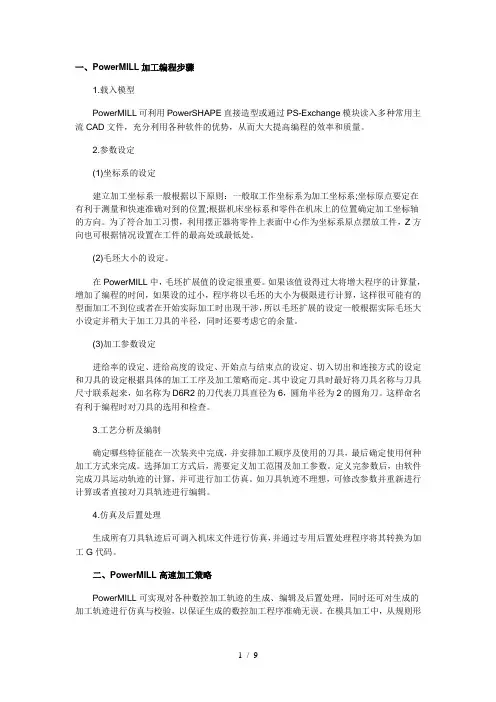
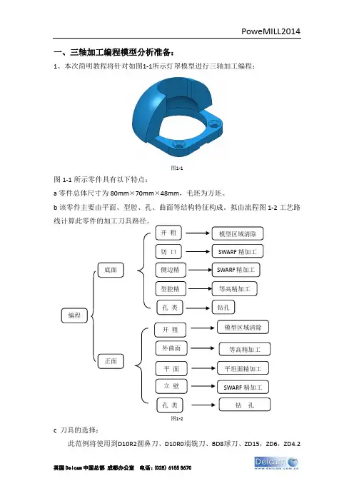
一、PowerMILL加工编程步骤1.载入模型PowerMILL可利用PowerSHAPE直接造型或通过PS-Exchange模块读入多种常用主流CAD文件,充分利用各种软件的优势,从而大大提高编程的效率和质量。
2.参数设定(1)坐标系的设定建立加工坐标系一般根据以下原则:一般取工作坐标系为加工坐标系;坐标原点要定在有利于测量和快速准确对到的位置;根据机床坐标系和零件在机床上的位置确定加工坐标轴的方向。
为了符合加工习惯,利用摆正器将零件上表面中心作为坐标系原点摆放工件,Z方向也可根据情况设置在工件的最高处或最低处。
(2)毛坯大小的设定。
在PowerMILL中,毛坯扩展值的设定很重要。
如果该值设得过大将增大程序的计算量,增加了编程的时间,如果设的过小,程序将以毛坯的大小为极限进行计算,这样很可能有的型面加工不到位或者在开始实际加工时出现干涉,所以毛坯扩展的设定一般根据实际毛坯大小设定并稍大于加工刀具的半径,同时还要考虑它的余量。
(3)加工参数设定进给率的设定、进给高度的设定、开始点与结束点的设定、切入切出和连接方式的设定和刀具的设定根据具体的加工工序及加工策略而定。
其中设定刀具时最好将刀具名称与刀具尺寸联系起来,如名称为D6R2的刀代表刀具直径为6,圆角半径为2的圆角刀。
这样命名有利于编程时对刀具的选用和检查。
3.工艺分析及编制确定哪些特征能在一次装夹中完成,并安排加工顺序及使用的刀具,最后确定使用何种加工方式来完成。
选择加工方式后,需要定义加工范围及加工参数。
定义完参数后,由软件完成刀具运动轨迹的计算,并可进行加工仿真。
如刀具轨迹不理想,可修改参数并重新进行计算或者直接对刀具轨迹进行编辑。
4.仿真及后置处理生成所有刀具轨迹后可调入机床文件进行仿真,并通过专用后置处理程序将其转换为加工G代码。
二、PowerMILL高速加工策略PowerMILL可实现对各种数控加工轨迹的生成、编辑及后置处理,同时还可对生成的加工轨迹进行仿真与校验,以保证生成的数控加工程序准确无误。
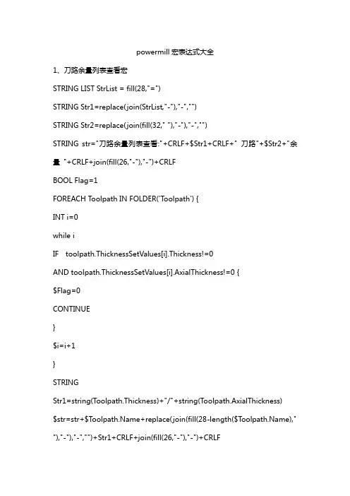
powermill宏表达式大全1、刀路余量列表查看宏STRING LIST StrList = fill(28,"=")STRING Str1=replace(join(StrList,"-"),"-","")STRING Str2=replace(join(fill(32," "),"-"),"-","")STRING str="刀路余量列表查看:"+CRLF+$Str1+CRLF+" 刀路"+$Str2+"余量"+CRLF+join(fill(26,"-"),"-")+CRLFBOOL Flag=1FOREACH Toolpath IN FOLDER('Toolpath') {INT i=0while iIF toolpath.ThicknessSetValues[i].Thickness!=0AND toolpath.ThicknessSetValues[i].AxialThickness!=0 {$Flag=0CONTINUE}$i=i+1}STRINGStr1=string(Toolpath.Thickness)+"/"+string(Toolpath.AxialThickness) $str=str+$+replace(join(fill(28-length($T )," "),"-"),"-","")+Str1+CRLF+join(fill(26,"-"),"-")+CRLF}IF FLAG {VIEW MODEL ; SHADE RAINBOW} ELSE {VIEW MODEL ; SHADE VTHICKNESS}MACRO PAUSE $str2、选面产生孔特征宏CREATE FEATURESET ; FORM FEATURE FEATURECREATEEDIT FEATURECREATE TYPE HOLE EDIT FEATURECREATE CIRCULAR ON EDIT FEATURECREATE FILTER CURVES EDIT FEATURECREATE TOPDEFINE ABSOLUTE EDIT FEATURECREATE BOTTOMDEFINE ABSOLUTEEDIT FEATURECREATE TOPDEFINE MAXINPUTEDIT FEATURECREATE BOTTOMDEFINE MININPUTEDIT FEATURESET ; INSERT POINTSFEATURE CANCEL3、单刀路碰撞检查宏DIALOGS MESSAGE ONFORM COLLISIONEDIT COLLISION TYPE COLLISIONEDIT COLLISION SCOPE ALLEDIT COLLISION SPLIT_TOOLPATH YEDIT COLLISION SPLIT_TOOLPATH NEDIT COLLISION SHANK_CLEARANCE "0.5"EDIT COLLISION HOLDER_CLEARANCE "0.5"EDIT COLLISION DEPTH NEDIT COLLISION DEPTH YEDIT COLLISION ADJUST_TOOL YEDIT COLLISION APPLYCOLLISION ACCEPT4、单刀路过切检查宏FORM COLLISIONEDIT COLLISION TYPE GOUGEEDIT COLLISION APPLYCOLLISION ACCEPT5、NC批量改名-序号+刀具名+RF宏//命名方式:序号+刀具名+RFINT i=1FOREACH NC IN FOLDER('NCProgram') {STRING NCName=STRING ToolName=""STRING Type="R"REAL m=0FOREACH Toolpath IN components(entity('NCProgram', NCName)) {$ToolName=IF entity('Toolpath',).Strategy=='drill' {$m=entity('Toolpath',).Drill.Thickness} else {$m=entity('Toolpath',).Thickness}Break}IF m$Type='F'}STRING Cmd='RENAME NCProgram '+$NCName+' '+i+'-'+$ToolName+'-'+$TypeDOCOMMAND $Cmd$i=i+1}6、批量命名刀路-序号+刀具名宏DIALOGS MESSAGE OFFDIALOGS ERROR OFFINT i=1FOREACH toolpath IN folder('TOOLPATH') {STRING thname=STRING LIST StrList=tokens(toolname,"_")STRING NewName=select(iRENAME TOOLPATH $thname $NewName$i=i+1}DIALOGS MESSAGE OFFDIALOGS ERROR OFF7、Z轴移动边界宏string prompt="输入边界沿着Z轴移动的距离:"REAL i=0bool err=0do {$i=input $prompt$err=ERROR iif err {$prompt="请输入一个数值:"} else {MODE NOGUI GEOMETRY_TRANSFORM START BOUNDARY ; MODE NOGUI TRANSFORM TYPE TRANSLATEMODE NOGUI TRANSFORM ORIGIN ACTIVE_WORKPLANE MODE NOGUI COORDINPUT COORDTYPE RELATIVE//相对移动MODE NOGUI COORDINPUT COORDINATES 0 0 $iMODE NOGUI GEOMETRY_TRANSFORM FINISH ACCEPT}} while err8、Z轴移动参考线宏string prompt="输入边界沿着Z轴移动的距离:"REAL i=0bool err=0do {$i=input $prompt$err=ERROR iif err {$prompt="请输入一个数值:"} else {MODE NOGUI GEOMETRY_TRANSFORM START PATTERN ; MODE NOGUI TRANSFORM TYPE TRANSLATEMODE NOGUI TRANSFORM ORIGIN ACTIVE_WORKPLANE MODE NOGUI COORDINPUT COORDTYPE RELATIVE//相对移动MODE NOGUI COORDINPUT COORDINATES 0 0 $iMODE NOGUI GEOMETRY_TRANSFORM FINISH ACCEPT}} while err9、锁定Z-扩展XY方向宏string prompt="输入毛坯扩展的数值:" REAL i=0bool err=0do {$i=input $prompt$err=ERROR iif err {$prompt="请输入一个数值:"} else {FORM BLOCKEDIT BLOCKTYPE BOXEDIT BLOCK LIMITTYPE MODEL EDIT BLOCK ALL UNLOCKEDIT BLOCK ZLEN LOCKEDIT BLOCK ZMAX LOCKEDIT BLOCK ZMIN LOCKEDIT BLOCK RESETLIMIT $iEDIT BLOCK RESETBLOCK ACCEPTDRAW BLOCKbreak}} while err10、批量安全高度(不激活刀路)宏DIALOGS MESSAGE OFFDIALOGS ERROR OFFSTRING a= "输入安全高度"int q= ""$q= input $aFOREACH c IN folder('TOOLPATH') {EDIT PAR "entity('toolpath',$).Rapid.Plane.Distance" $q }DIALOGS MESSAGE ONDIALOGS ERROR ON。
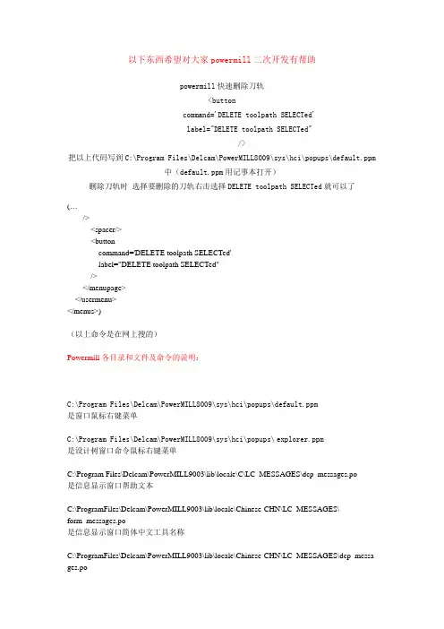
以下东西希望对大家powermill二次开发有帮助powermill快速删除刀轨<buttoncommand='DELETE toolpath SELECTed'label="DELETE toolpath SELECTed"/>把以上代码写到C:\Program Files\Delcam\PowerMILL8009\sys\hci\popups\default.ppm中(default.ppm用记事本打开)删除刀轨时选择要删除的刀轨右击选择DELETE toolpath SELECTed就可以了(…/><spacer/><buttoncommand='DELETE toolpath SELECTed'label="DELETE toolpath SELECTed"/></menupage></usermenu></menus>)(以上命令是在网上搜的)Powermill各目录和文件及命令的说明:C:\Program Files\Delcam\PowerMILL8009\sys\hci\popups\default.ppm是窗口鼠标右键菜单C:\Program Files\Delcam\PowerMILL8009\sys\hci\popups\explorer.ppm是设计树窗口命令鼠标右键菜单C:\Program Files\Delcam\PowerMILL9003\lib\locale\C\LC_MESSAGES\dcp_messages.po是信息显示窗口帮助文本C:\ProgramFiles\Delcam\PowerMILL9003\lib\locale\Chinese-CHN\LC_MESSAGES\form_messages.po是信息显示窗口简体中文工具名称C:\ProgramFiles\Delcam\PowerMILL9003\lib\locale\Chinese-CHN\LC_MESSAGES\dcp_messa ges.po是信息显示窗口简体中文帮助文本C:\ProgramFiles\Delcam\PowerMILL9003\lib\locale\Chinese-TWN\LC_MESSAGES\form_messages.po是信息显示窗口繁体中文工具名称C:\ProgramFiles\Delcam\PowerMILL9003\lib\locale\Chinese-TWN\LC_MESSAGES\dcp_messa ges.po是信息显示窗口繁体中文帮助文本C:\ProgramFiles\Delcam\PowerMILL9003\lib\locale\English\LC_MESSAGES\form_messages.po是信息显示窗口英文工具名称C:\ProgramFiles\Delcam\PowerMILL9003\lib\locale\ English\LC_MESSAGES\dcp_messages.po 是信息显示窗口英文帮助文本C:\Program Files\Delcam\PowerMILL9003\lib\locale\C\LC_MESSAGES\ form_messages.po是信息显示窗口工具名称C:\Program Files\Delcam\PowerMILL9003\lib\locale\C\HELP\ help.alias是窗口?号帮助地址C:\Program Files\Delcam\PowerMILL9003\lib\locale\C\HELP\ Pmill.chm是powermill帮助文件C:\Program Files\Delcam\PowerMILL9003\lib\locale\C\PARREF是命令信息C:\Program Files\Delcam\PowerMILL9003\lib\locale\C\PARSUM\ parameters.htmlPowermill参数摘要C:\Program Files\Delcam\PowerMILL9003\lib\locale\C\RESOURCE\ pmill.rcPowermill文件格式命令C:\Program Files\Delcam\PowerMILL9003\lib\macro是宏文件目录C:\Program Files\Delcam\PowerMILL9003\lib\macro\pminch.mac是英制默认宏文件C:\Program Files\Delcam\PowerMILL9003\lib\macro\pmlocal.mac是开始启动宏文件C:\Program Files\Delcam\PowerMILL9003\lib\macro\pmstartup.mac是主要启动宏文件C:\Program Files\Delcam\PowerMILL9003\lib\macro\pmuser.mac是用户启动宏文件C:\Program Files\Delcam\PowerMILL9003\lib\newfeatures\C\newfeatures.html是新增功能演示C:\Program Files\Delcam\PowerMILL9003\lib\newfeatures\Russian\newfeatures.html 是俄语新增功能演示C:\Program Files\Delcam\PowerMILL9003\lib\newfeatures\images是新增功能演示图片目录C:\Program Files\Delcam\PowerMILL9003\lib\newfeatures\videos是新增功能演示视频目录C:\Program Files\Delcam\PowerMILL9003\file\browser是DELCAM公司产品目录C:\Program Files\Delcam\PowerMILL9003\file\examples是范例文件目录C:\Program Files\Delcam\PowerMILL9003\file\examples\MachineData是模拟机器文件目录C:\Program Files\Delcam\PowerMILL9003\file\examples\Patterns是参考线文件目录C:\Program Files\Delcam\PowerMILL9003\file\setup-sheets是程序单目录C:\Program Files\Delcam\PowerMILL9003\file\templates是刀具路径策略目录。

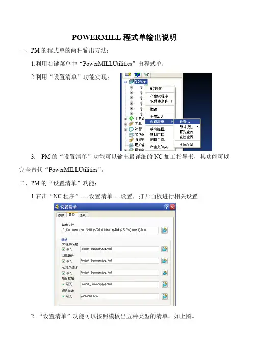
POWERMILL程式单输出说明一、PM的程式单的两种输出方法:1.利用右键菜单中“PowerMILLUtilities”出程式单;2.利用“设置清单”功能实现;3. PM的“设置清单”功能可以输出最详细的NC加工指导书,其功能可以完全替代“PowerMILLUtilities”。
二、PM的“设置清单”功能:1.右击“NC程序”----设置清单----设置,打开面板进行相关设置2. “设置清单”功能可以按照模板出五种类型的清单,如上图。
其中:“项目标题”可输出整个加工项目的总体信息“NC程序标题”可输出每一条“NC程序”的总体信息“刀具路径”可输出每一条加工刀路(即每一个加工策略)的信息“项目综述”对整个项目的每条加工刀路作信息的输出“NC程序综述”对每一NC程序中包含的每条加工刀路作信息的输出可以认为PM能输出最详细的加工信息,但是由于它在统计时基于每一条刀具路径,而不是每一条输出G代码的“NC程序”,因此在输出CNC车间使用的程式单时也有“太详细”的弊端。
三、CNC车间程式单输出方法:1. 将文件“yangfanbill.html”复制到模板路径下:… …\Delcam\PowerMILL8009\file\setup-sheets\2.打开设置面板,只勾选最后一项,指定模板“yangfanbill.html”,设置输出路径(可默认)。
4.设置快照图像5.输出:结果如下:这张程序单没有经过人工修改,前面的顺序检查增强了它的易读性,那是对应刀路的注。
四、关于程序单的定制和编辑:最好使用网页软件如Frontpage或Dreamwaver编辑,有及时预览功能,其它软件可能产生乱码。
以下东西希望对大家powermill二次开发有帮助powermill快速删除刀轨<buttoncommand='DELETE toolpath SELECTed'label="DELETE toolpath SELECTed"/>把以上代码写到C:\Program Files\Delcam\PowerMILL8009\sys\hci\popups\default.ppm中(default.ppm用记事本打开)删除刀轨时选择要删除的刀轨右击选择DELETE toolpath SELECTed就可以了(…/><spacer/><buttoncommand='DELETE toolpath SELECTed'label="DELETE toolpath SELECTed"/></menupage></usermenu></menus>)(以上命令是在网上搜的)Powermill各目录和文件及命令的说明:C:\Program Files\Delcam\PowerMILL8009\sys\hci\popups\default.ppm是窗口鼠标右键菜单C:\Program Files\Delcam\PowerMILL8009\sys\hci\popups\explorer.ppm是设计树窗口命令鼠标右键菜单C:\Program Files\Delcam\PowerMILL9003\lib\locale\C\LC_MESSAGES\dcp_messages.po是信息显示窗口帮助文本C:\ProgramFiles\Delcam\PowerMILL9003\lib\locale\Chinese-CHN\LC_MESSAGES\form_messages.po是信息显示窗口简体中文工具名称C:\ProgramFiles\Delcam\PowerMILL9003\lib\locale\Chinese-CHN\LC_MESSAGES\dcp_messa ges.po是信息显示窗口简体中文帮助文本C:\ProgramFiles\Delcam\PowerMILL9003\lib\locale\Chinese-TWN\LC_MESSAGES\form_messages.po是信息显示窗口繁体中文工具名称C:\ProgramFiles\Delcam\PowerMILL9003\lib\locale\Chinese-TWN\LC_MESSAGES\dcp_messa ges.po是信息显示窗口繁体中文帮助文本C:\ProgramFiles\Delcam\PowerMILL9003\lib\locale\English\LC_MESSAGES\form_messages.po是信息显示窗口英文工具名称C:\ProgramFiles\Delcam\PowerMILL9003\lib\locale\ English\LC_MESSAGES\dcp_messages.po 是信息显示窗口英文帮助文本C:\Program Files\Delcam\PowerMILL9003\lib\locale\C\LC_MESSAGES\ form_messages.po是信息显示窗口工具名称C:\Program Files\Delcam\PowerMILL9003\lib\locale\C\HELP\ help.alias是窗口?号帮助地址C:\Program Files\Delcam\PowerMILL9003\lib\locale\C\HELP\ Pmill.chm是powermill帮助文件C:\Program Files\Delcam\PowerMILL9003\lib\locale\C\PARREF是命令信息C:\Program Files\Delcam\PowerMILL9003\lib\locale\C\PARSUM\ parameters.htmlPowermill参数摘要C:\Program Files\Delcam\PowerMILL9003\lib\locale\C\RESOURCE\ pmill.rcPowermill文件格式命令C:\Program Files\Delcam\PowerMILL9003\lib\macro是宏文件目录C:\Program Files\Delcam\PowerMILL9003\lib\macro\pminch.mac是英制默认宏文件C:\Program Files\Delcam\PowerMILL9003\lib\macro\pmlocal.mac是开始启动宏文件C:\Program Files\Delcam\PowerMILL9003\lib\macro\pmstartup.mac是主要启动宏文件C:\Program Files\Delcam\PowerMILL9003\lib\macro\pmuser.mac是用户启动宏文件C:\Program Files\Delcam\PowerMILL9003\lib\newfeatures\C\newfeatures.html是新增功能演示C:\Program Files\Delcam\PowerMILL9003\lib\newfeatures\Russian\newfeatures.html 是俄语新增功能演示C:\Program Files\Delcam\PowerMILL9003\lib\newfeatures\images是新增功能演示图片目录C:\Program Files\Delcam\PowerMILL9003\lib\newfeatures\videos是新增功能演示视频目录C:\Program Files\Delcam\PowerMILL9003\file\browser是DELCAM公司产品目录C:\Program Files\Delcam\PowerMILL9003\file\examples是范例文件目录C:\Program Files\Delcam\PowerMILL9003\file\examples\MachineData是模拟机器文件目录C:\Program Files\Delcam\PowerMILL9003\file\examples\Patterns是参考线文件目录C:\Program Files\Delcam\PowerMILL9003\file\setup-sheets是程序单目录C:\Program Files\Delcam\PowerMILL9003\file\templates是刀具路径策略目录。
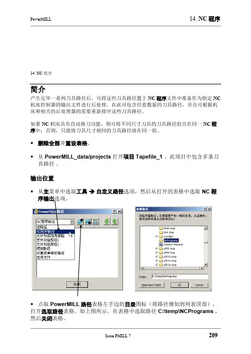
14. NC 程序简介产生完毕一系列刀具路径后,可将这些刀具路径置于NC程序文件中准备作为指定NC 机床控制器的输出文件进行后处理。
在此可包含任意数量的刀具路径,并且可根据机床和相关的后处理器的需要重新排序这些刀具路径。
如果NC机床具有自动换刀功能,则可将不同尺寸刀具的刀具路径组合在同一NC程序中;否则,只能将刀具尺寸相同的刀具路径放在同一组。
∙删除全部并重设表格。
∙从PowerMILL_data/projects打开项目Tapefile_1。
此项目中包含多条刀具路径。
输出位置∙从主菜单中选取工具 自定义路径选项,然后从打开的表格中选取NC程序输出选项。
∙点取PowerMILL路径表格左手边的目录图标(将路径增加到列表顶部),打开选取路径表格。
如上图所示,在表格中选取路径C:\temp\NCPrograms,然后关闭表格。
注:以上目标目录NCPrograms 必须已存在,否则不能输出NC 程序文件。
设置参数∙ 在浏览器中右击NC 程序 → 参数选择。
∙ 点取表格中的目录图标,打开选取机床选项文件名表格。
选项文件决定了在NC 程序中应用哪种NC 格式。
∙ 选取文件 heid.opt ,这样将以 机床语言格式Heidenhain 输出NC 文件。
点 取打开和接受。
产生 NC 程序∙ 在浏览器域中右击 NC 程序 → 产生NC 程序。
∙ 输入名称 Job_646_top 并接受表格。
∙ 点取浏览器NC 程序旁的 +/- 图标,打开或关闭job_646_top 显示。
下面即 可将一部分或全部刀具路径增加到此激活的NC 程序中。
∙ 在浏览器中用左鼠标键点取并保持区域清除图标,然后拖动光标,此时光标上附加上了一虚幻图像。
∙ 将此虚幻图像拖动到激活的NC 程序 (Job_646_top) 上,然后释放鼠标 键。
点取浏览器job_646_top 旁的 +/- 图标,即可看到刀具路径 (Roughing_16)的内容已存在在此激活NC 程序中。
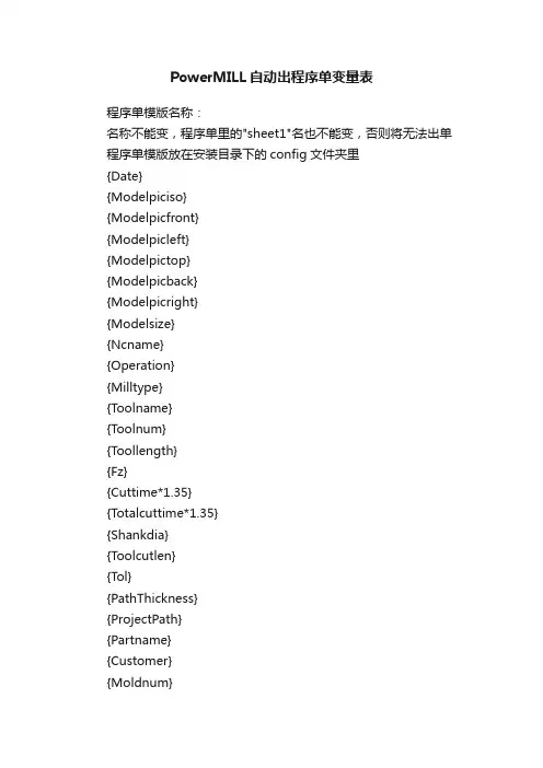
PowerMILL自动出程序单变量表程序单模版名称:名称不能变,程序单里的"sheet1"名也不能变,否则将无法出单程序单模版放在安装目录下的config文件夹里{Date}{Modelpiciso}{Modelpicfront}{Modelpicleft}{Modelpictop}{Modelpicback}{Modelpicright}{Modelsize}{Ncname}{Operation}{Milltype}{Toolname}{Toolnum}{Toollength}{Fz}{Cuttime*1.35}{Totalcuttime*1.35}{Shankdia}{Toolcutlen}{Tol}{PathThickness}{ProjectPath}{Partname}{Customer}{Moldnum}{MT}{Mrl}{Spindlespeed}{Cuttingfeed}名称:CNCSTEEL.xls代表钢料模版,CNCELEC.xls代表电极模版名称不能变,程序单里的"sheet1"名也不能变,否则将无法出单程序单模版放在安装目录下的config文件夹里当前时间三维图前视图左视图俯视图后视图右视图模型尺寸程序名称刀路名称加工类型(开粗、光刀)按刀路名称首字母区分,R代表开粗,F 代表光刀。
刀名刀号刀长加工深度加工时间 1.35表示倍数加工总时间 1.35表示倍数刀柄直径避空公差余量项目路径零件名称客户名称模具编号机床材料转速进给备注:变量必须放在100行70列之内。

14. 设置清单简介全部的PowerMILL项目数据,如刀具定义、整体刀具路径尺寸和刀具路径图像等都可被自动记录和打印。
这些对运行程序的CNC机床操作者来说很有帮助。
设置清单可通过PowerMILL浏览器中的NC程序域产生。
•删除全部并重设表格。
•从PowerMILL_data/Projects 打开项目Tapefile_1。
产生设置清单前需产生一NC程序。
•右击浏览器中的NC 程序 参数选择•点击文件夹图标,打开选取机床选项文件名表格。
选取,然后应用并接受表格。
右击浏览器中的NC 程序。
选取产生NC程序。
•输入名称Job_650_top,然后接受表格。
•右击刀具路径。
•选取增加到NC程序。
于是全部刀具路径即增加到NC程序中。
右击此NC程序,然后选取设置选项,打开下图所示表格。
•表格中的某些域,如项目等已自动填写。
填写表格中的其它内容。
•确认没激活任何刀具路径且模型呈阴影显示状态。
右击此NC程序,然后如图所示,选取当前查看选项。
于是系统即捕捉拍照一模型图像,这个图像将自动用在设置清单的首页。
右击此NC程序,此次选取全部刀具路径。
于是系统即捕捉拍照已选NC程序中的全部刀具路径图像。
设置清单中,每条刀具路径具有各自单独的页面。
再次右击此NC程序,此次选取预览选项。
屏幕左边是设置清单索引,屏幕的右边是设置清单首页。
•点击某些刀具路径设置清单。
•点击综述页面1。
•右击此NC程序。
•选取设置清单 – 输出。
输出选项将全部设置清单以HTML文件格式保存在当前项目文件夹中。
可在PowerMILL中直接打印设置清单,也可在输出后,通过打印HTML文档来打印。
自定义设置清单通过编辑HTML模板可用户化设置清单输出,使它更适合于各个用户的特殊要求。
HTML模板文件最好是使用某个HTML 编辑软件来编辑。
在英特网上可找到一些免费的HTML编辑软件,也可使用Microsoft Word来编辑,但是使用Microsoft Word 的缺点是通常不可预知编辑后的结果。
{Tolerance}{Block.Type}{Block.CoordinateSystem}{Filter.Type}{Filter.Factor}{BoundaryLimit.Keep} {BoundaryLimit.Tool}{ToolAxis.Type}{Block.Limits.XMin}{Block.Limits.XMax}{Block.Limits.YMin}{Block.Limits.YMax}{Block.Limits.ZMin}{Block.Limits.ZMax}{tool.NumberOfFlutes}{tool.Number.Value}{tool.Length}{tool.Identifier}{tool.Diameter}{Verification.Clearance.Head} {Verification.CheckAgainst} {Units}{ToolpathType}{ToolAxis.Type} {ThicknessSetValues.Thickness} {Strategy}{Stepdown}{StartPoint.Type}{StartPoint.Distance} {SpindleSpeed.Value}{Rapid.Type}{Rapid.SafeArea}{Rapid.Plane.PlungeDistance} {Rapid.Plane.Normal}{Ordering}{Filter.Type}{Filter.Factor}{FeedRate.Rapid}{FeedRate.Plunging.Value} {FeedRate.FeedPerTooth.Value} {FeedRate.CuttingSpeed.Value} {FeedRate.Cutting.Value} {CutDirection}{AreaClearance.Profile.CutDirection} {Connections.PlungeDistance} {Connections.MoveDirection} {Connections.MaxMoveExtension}{Connections.IncrementalMode} {BoundaryLimit.Tool}{BoundaryLimit.Keep}{Block.Type}{Block.Limits.XMax}{Block.Limits.XMin}{Block.Limits.YMax}{Block.Limits.YMin}{Block.Limits.ZMax}{Block.Limits.ZMin}{AreaClearance.Offset.Type} {AreaClearance.Offset.Preference} {AreaClearance.LeadIn.Type}下面有关图像的参数命令{CompanyLogo}{DelcamLogo}{PMillLogo}{CompanyLogoSRC}{DelcamLogoSRC}{PMillLogoSRC}{setupsheets.project.image_tag} {setupsheets.ncprogram.image_tag} {setupsheets.toolpath.image_tag} {setupsheets.project.image_file_name} {setupsheets.ncprogram.image_file_name} {setupsheets.toolpath.image_file_name} {setupsheets.tool.vml}{ToolType}{ToolTypeSRC}下面有关项目的参数命令{project.date}{project.day}{project.month}{project.notes}{project.path}{project.programmer}{project.time}{project.year}{version}{codebase}{project.customer}{project.partname}{project.orderno}{setupsheets.model.file_name} {setupsheets.model.file_path}{units}{PD_TotalTime}下面有关NC程序的参数命令{project.nc_path}{ncprogram.programmer}{ncprogram.notes}{ncprogram}{ncprogram.partname}{ncprogram.shortname}{ncprogram.specialname}{ncprogram.counter}{ncprogram.date}{ncprogram.option_name}{PD_CutTime}{PD_OutputDirectory}{PD_TapFile}{PD_Units}{ncprogram.workplane}{ncprogram.model.limits.x.max}{ncprogram.model.limits.x.min}{ncprogram.model.limits.y.max}{ncprogram.model.limits.y.min}{ncprogram.model.limits.z.max}{ncprogram.model.limits.z.min}{ncprogram.OptionFile}{ncprogram.statistics.tool_lifts} {ncprogram.statistics.totaltime} {ncprogram.tool_datum}{ncprogram.tool_lifts}下面有关刀具路径策略的参数命令{AllowToolOutsideBlock} {AlternateCutDirection}{AngularDirection}{AngularLimits.End}{AngularLimits.Start}{AngularLimits2.End}{AngularLimits2.Start}{AngularSmoothing}{AngularStepover}{AreaClearance.CalculationType} {AreaClearance.FeatureData}{AreaClearance.LeadIn.ApproachOutside} {AreaClearance.LeadIn.Drill.Pattern} {AreaClearance.LeadIn.Drill.TemplateName} {AreaClearance.LeadIn.Ramp.CircleDiameter} {AreaClearance.LeadIn.Ramp.Follow} {AreaClearance.LeadIn.Ramp.LimitLength.Active} {AreaClearance.LeadIn.Ramp.LimitLength.Value}{AreaClearance.LeadIn.Ramp.MaxZigAngle} {AreaClearance.LeadIn.Ramp.ZagAngle.Active} {AreaClearance.LeadIn.Ramp.ZagAngle.Value} {AreaClearance.LeadIn.Type}{AreaClearance.Offset.Links}{AreaClearance.Offset.Order}{AreaClearance.Offset.Preference} {AreaClearance.Offset.RemoveCusps} {AreaClearance.Offset.SmallestFirst} {AreaClearance.Offset.SmoothingAllowance.Active} {AreaClearance.Offset.SmoothingAllowance.Value} {AreaClearance.Offset.Trochoids.Allowance}{AreaClearance.Offset.Trochoids.Constraint.Active} {AreaClearance.Offset.Trochoids.Constraint.MaxDiame ter}{AreaClearance.Offset.Trochoids.Constraint.MaxStepa long}{AreaClearance.Offset.Trochoids.Constraint.MinDiame ter}{AreaClearance.Offset.Trochoids.Distribution} {AreaClearance.Offset.Type}{AreaClearance.Profile.CornerRadius.Active} {AreaClearance.Profile.CornerRadius.Value} {AreaClearance.Profile.CutDirection} {AreaClearance.Profile.Final.Active} {AreaClearance.Profile.Final.Allowance} {AreaClearance.Profile.Final.Location}{AreaClearance.Profile.Outside}{AreaClearance.Profile.Sequence}{AreaClearance.Profile.SlotSide}{AreaClearance.Raster.Angle.Mode} {AreaClearance.Raster.Angle.Value} {AreaClearance.Raster.ConstantStepover}{AreaClearance.Raster.MachineAll} {AreaClearance.Raster.MinimiseFullWidthCuts}{AreaClearance.Raster.PerpendicularPass} {AreaClearance.Raster.Style}{AreaClearance.Rest.Active}{AreaClearance.Rest.ExpandArea}{AreaClearance.Rest.RefMethod}{AreaClearance.Rest.ReferenceType} {AreaClearance.Rest.ThresholdThickness} {AreaClearance.Rest.Toolpath}{ePreviousZHeights} {AreaClearance.SliceData}{AreaClearance.Slicer.CutterCompensation.MinRadius}{AreaClearance.Slicer.CutterCompensation.Type} {AreaClearance.Slicer.FileName}{AreaClearance.Slicer.Filter.Active} {AreaClearance.Slicer.Filter.EnclosedOnly} {AreaClearance.Slicer.Filter.Mode} {AreaClearance.Slicer.Filter.Threshold} {AreaClearance.Slicer.Flat.AllowToolOutside}{AreaClearance.Slicer.Flat.ApproachAllowance}{AreaClearance.Slicer.Flat.HoleFilterThreshold.Acti ve}{AreaClearance.Slicer.Flat.HoleFilterThreshold.Valu e}{AreaClearance.Slicer.Flat.MultipleCuts.Active} {AreaClearance.Slicer.Flat.MultipleCuts.FinalStepdo wn.Active}{AreaClearance.Slicer.Flat.MultipleCuts.FinalStepdo wn.Value}{AreaClearance.Slicer.Flat.MultipleCuts.Number} {AreaClearance.Slicer.Flat.MultipleCuts.Stepdown} {AreaClearance.Slicer.Flat.Tolerance}{AreaClearance.Slicer.Type}{AreaClearance.SlicerReference}{AreaClearance.ZHeights.Automatic}{AreaClearance.ZHeights.ConstantStepdown} {AreaClearance.ZHeights.Flats}{AreaClearance.ZHeights.List}{AreaClearance.ZHeights.List.Type} {AreaClearance.ZHeights.List.Value} {AreaClearance.ZHeights.Stepdown}{AreaClearance.ZHeights.Type}{AreaClearance.ZHeights.Value}{AxialDepthOfCut.Value} {AxialOffset} {AxialSmoothingTolerance} {AxialThickness} {AxisTolerance}{azimuth} {BaseLimitingWorkplane} {BliskAxisElevation.Angle} {BliskAxisElevation.Axis}{BliskMachiningType} {BliskOperation} {BottomWireframe} {chamfer.clearance} {chamfer.width} {ClosedOffsets} {CornerOutput} {CornerRadius.Active}{CornerRadius.Value}{cusp.active}{cusp.height}{Cusp.MaxStepdown}{CutDirection}{Drill.ChamferDiameter} {drill.clearance}{drill.clockwise}{ponentDepth}{drill.depth.value} {Drill.DepthType}{Drill.DraftAngle.Value} {Drill.DwellTime}{Drill.FeedReduction} {Drill.GougeCheck}{Drill.HoleData}{Drill.HoleIndex}{Drill.IncrementalStart} {Drill.InitialZ}{Drill.MinPeck}{drill.overlap}{Drill.PeckDecrement} {Drill.PeckDepth.Value} {drill.pitch}{Drill.RapidRetract} {Drill.ReduceFeedDistance}{drill.retract}{Drill.RetractFactor} {Drill.RetractFeedFactor} {Drill.StartFeedDistance}{Drill.StartFeedReduction}{Drill.SubsidiaryPeck} {Drill.TopType}{drill.type}{eCycles}{erParameter} {EdgeTolerance} {elevation}{EndPoint.Distance}{EndPoint.ManualToolAxis} {EndPoint.Mode}{EndPoint.MoveDirection} {EndPoint.Position} {EndPoint.SeparateFinalRetract}{EndPoint.ToolAxis} {EndPoint.Type}{FanAtEnd}{FanningDistance} {MinimumStepover} {MultiPencilIndependantSegments} {MultipleCuts} {MultipleCutsStepdown.Active} {MultipleCutsStepdown.Value} {NumberOfBlades} {OffsetDirection}{overlap}{ParametricLimits.Active} {ParametricLimits.End} {ParametricLimits.Start} {ParametricLimits2.Active} {ParametricLimits2.End} {ParametricLimits2.Start} {ParametricOffsetEndCurve} {ParametricOffsetStartCurve} {PerpendicularPass}{Plunge.CoreRadius}{Plunge.PullBack} {PortAreaClearanceMode} {PortAreaClearancePartialSlices} {PortAreaClearancePlaneLimits} {PortAreaClearanceRampDiameter} {PortAreaClearanceRampSlope} {PortOverlap.DistanceToLiftStart}{PortOverlap.Length} {PortOverlap.LiftHeight} {PortOverlap.MidPoint} {PortToolClearance} {ProjectionDirection} {ProjectionOrder} {ProjectionPatternDirection} {ProjectionRange.Automatic} {ProjectionRange.Max} {ProjectionRange.Min} {ProjectionStyle} {ProjectionSurfaceUnits} {RadialDepthOfCut.Value} {RadialOffset}{RasterAngle}{RemoveShallowSlices}{ReverseAxis}{RotaryType}{RulingsTolerance}{spiral}{StartCorner}{StartOnPattern}{StartPoint.Distance} {StartPoint.ManualToolAxis} {StartPoint.Mode}{StartPoint.MoveDirection} {StartPoint.Position} {StartPoint.SeparateFirstApproach}{StartPoint.ToolAxis} {StartPoint.Type}{stepdown}{StepdownLimit.Active} {StepdownLimit.Value}{stepover}{StepoverLimit.Active} {StepoverLimit.Value}{strategy}{SurfaceNormalSmoothingTolerance} {SurfaceSide}{SwarfBasePosition}{thickness}{ThicknessSets}{ThresholdAngle}{tolerance}下面有关刀具路径连接的参数命令{Connections.ApproachDistance} {Connections.ArcFittingRadius.Active} {Connections.ArcFittingRadius.Value} {Connections.AxisDiscontinuityThreshold}{Connections.DefaultLink}{Connections.DefaultLink.Type} {Connections.ExtendMove}{Connections.FirstLeadIn.Angle} {Connections.FirstLeadIn.Distance} {Connections.FirstLeadIn.Radius} {Connections.FirstLeadIn.Ramp.CircleDiameter} {Connections.FirstLeadIn.Ramp.ClosedProfiles}{Connections.FirstLeadIn.Ramp.Extend}{Connections.FirstLeadIn.Ramp.Follow} {Connections.FirstLeadIn.Ramp.Height.Type} {Connections.FirstLeadIn.Ramp.Height.Value} {Connections.FirstLeadIn.Ramp.LimitLength.Active} {Connections.FirstLeadIn.Ramp.LimitLength.Value} {Connections.FirstLeadIn.Ramp.MaxZigAngle}{Connections.FirstLeadIn.Ramp.ZagAngle.Active} {Connections.FirstLeadIn.Ramp.ZagAngle.Value} {Connections.FirstLeadIn.Type}{Connections.GougeCheck}{Connections.HolderCheck}{Connections.IncrementalMode}{stLeadOut.Angle}{stLeadOut.Distance} {stLeadOut.Radius}{stLeadOut.Ramp.CircleDiameter} {stLeadOut.Ramp.ClosedProfiles} {stLeadOut.Ramp.Extend}{stLeadOut.Ramp.Follow} {stLeadOut.Ramp.Height.Type} {stLeadOut.Ramp.Height.Value} {stLeadOut.Ramp.LimitLength.Active} {stLeadOut.Ramp.LimitLength.Value} {stLeadOut.Ramp.MaxZigAngle}{stLeadOut.Ramp.ZagAngle.Active} {stLeadOut.Ramp.ZagAngle.Value} {stLeadOut.Type} {Connections.LeadIn}{Connections.LeadIn.Angle}{Connections.LeadIn.Distance}{Connections.LeadIn.Radius}{Connections.LeadIn.Ramp.CircleDiameter} {Connections.LeadIn.Ramp.ClosedProfiles} {Connections.LeadIn.Ramp.Extend}{Connections.LeadIn.Ramp.Follow} {Connections.LeadIn.Ramp.Height.Type} {Connections.LeadIn.Ramp.Height.Value} {Connections.LeadIn.Ramp.LimitLength.Active} {Connections.LeadIn.Ramp.LimitLength.Value} {Connections.LeadIn.Ramp.MaxZigAngle}{Connections.LeadIn.Ramp.ZagAngle.Active} {Connections.LeadIn.Ramp.ZagAngle.Value} {Connections.LeadIn.Type}{Connections.LeadInExtension.Angle} {Connections.LeadInExtension.Distance} {Connections.LeadInExtension.Radius} {Connections.LeadInExtension.Type} {Connections.LeadOut}{Connections.LeadOut.Angle}{Connections.LeadOut.Distance} {Connections.LeadOut.Radius}{Connections.LeadOut.Ramp.CircleDiameter} {Connections.LeadOut.Ramp.ClosedProfiles}{Connections.LeadOut.Ramp.Extend}{Connections.LeadOut.Ramp.Follow} {Connections.LeadOut.Ramp.Height.Type} {Connections.LeadOut.Ramp.Height.Value} {Connections.LeadOut.Ramp.LimitLength.Active} {Connections.LeadOut.Ramp.LimitLength.Value} {Connections.LeadOut.Ramp.MaxZigAngle}{Connections.LeadOut.Ramp.ZagAngle.Active} {Connections.LeadOut.Ramp.ZagAngle.Value} {Connections.LeadOut.Type}{Connections.LeadOutExtension.Angle} {Connections.LeadOutExtension.Distance} {Connections.LeadOutExtension.Radius} {Connections.LeadOutExtension.Type} {Connections.LeadsAtAxisDiscontinuities} {Connections.LeadsOnShortLinks} {Connections.LongLink}{Connections.LongLink.Type}{Connections.MaxMoveExtension} {Connections.MoveDirection}{Connections.MoveStartPoints}{Connections.OverlapDistance}{Connections.PlungeDistance} {Connections.RadialClearance}{Connections.RapidSkim} {connections.reorientate} {connections.resolve} {Connections.RetractDistance} {Connections.SeparateFirstLeadIn}{Connections.SeparateLastLeadOut} {Connections.ShankCheck} {Connections.ShortLink} {Connections.ShortLink.Type} {Connections.SkimDistance}{Connections.ThresholdDistance} {JoinRadius}{JoinTolerance}{rapid.box.corner}{Rapid.Box.ExcludedSurfaces.XMax} {Rapid.Box.ExcludedSurfaces.XMin} {Rapid.Box.ExcludedSurfaces.YMax}{Rapid.Box.ExcludedSurfaces.YMin} {Rapid.Box.ExcludedSurfaces.ZMax} {Rapid.Box.ExcludedSurfaces.ZMin} {Rapid.Box.XLength}{Rapid.Box.YLength}{Rapid.Box.ZLength}{rapid.cylinder.axis}{Rapid.Cylinder.PlungeRadius} {rapid.cylinder.point}{rapid.cylinder.radius}{Rapid.IncrementalSafeZ} {Rapid.IncrementalStartZ}{Rapid.MinimiseOffSurface} {rapid.plane.distance}{rapid.plane.normal}{Rapid.Plane.PlungeDistance}{Rapid.SafeArea}{rapid.sphere.centre}{Rapid.Sphere.PlungeRadius}{rapid.sphere.radius}{rapid.type}{rapid.workplane}下面有关刀具路径主轴转速和进给率的参数命令{AxialDepthOfCut.Value}{cut}{coolant.value}{FeedRate.Cutting.Value}{FeedRate.CuttingSpeed.Value}{FeedRate.Cycle}{FeedRate.DepthOfCut}{FeedRate.FeedPerTooth.Value}{FeedRate.PlungeFactor}{FeedRate.Plunging.Value}{FeedRate.Rapid}{FeedRate.SurfaceSlope}{eOverhang}{eWorkDiameter}{plunge}{rapid}{RadialDepthOfCut.Value}{spindle}{VariableFeedRate}下面有关刀具路径定义,推定和编辑的参数命令{computed}{coolant.value} {counter}{DatumX}{DatumY}{DatumZ}{degouge.active} {Degouge.EmbeddedMode} {degouge.method} {degouge.tolerance}{description}{DiscAxis.Elevation} {DiscAxis.Orientation} {EditHistory}{history.codebase} {history.cost}{history.hash} {History.HashVersion} {history.modified} {IDX}{height_above_model} {incomplete}{LimitMethod}{LinearLimits.End} {LinearLimits.Start} {LinearLimits2.End} {LinearLimits2.Start} {MaxDistanceBetweenPoints.Active}{MaxDistanceBetweenPoints.Value}{mesh.factor}{Mesh.MaxTriangleSize.Active}{Mesh.MaxTriangleSize.Value} {Method.FileName}{Method.SplitTolerance}{method.xml}{movement_type}{notes}{ordering}{operation} {ReferenceToolpath}{revision}{strategy}{sorting}{toolpath}{ToolpathType}{TP_TapFile}{TPXMax}{TPXMin}{TPYMax}{TPYMin}{TPZMax}{TPZMin}{Workplane}{WKPL_Name}{WKPL_X}{WKPL_Y}{WKPL_Z}{workplane.ncangle.x}{workplane.ncangle.y}{workplane.ncangle.z}下面有关刀具路径统计学参数命令{axial_thickness}{cut}{CutTime}{CutDir}{CutLength}feedrate.cutting}{feedrate.plunging}{global_thickness}{LevelMove}{linear_stepover}{plunge}{radial_thickness}{rapid}{SafeZ}{spindle}{SpindleSpeed.Value}{spindle_speed}{StartZ}{step}{stepdown}{thickness}{tolerance}{TotalTime}下面有关刀具和夹持参数命令{clearance.head}{clearance.holder}{clearance.shank}{CutLength}{CollisionAvoidance.Active} {CollisionAvoidance.Clearance.Holder} {CollisionAvoidance.Clearance.Shank} {CollisionAvoidance.Curve} {CollisionAvoidance.Direction} {CollisionAvoidance.Origin} {CollisionAvoidance.Type} {CollisionCheck}{comp_n_len} {comp_n_lower} {comp_n_upper}{tool.coolant} {MCLength} {overhang} {TapAng} {TapLen}{TH_Straight} {tool.description} {tool.diameter} {tool.drillAngle}{ToolID}{Tool.Holder[n].Length} {Tool.Holder[n].LowerDiameter} {Tool.Holder[n].UpperDiameter} {tool.identifier}{tool.length}{}{tool.number}{tool.NumberOfFlutes}{tool.gauge_length}{tool.holder_filename}{tool.holder_name}{tool.RoutingEndMillDiameter} {tool.TaperAngle}{tool.TaperDiameter}{tool.TaperHeight}{tool.tip_radius}{tool.TipRadiusCentre}{tool.ToolFamily}{tool.type}{tool.radius}{Tool.Shank[n].Length}{Tool.Shank[n].LowerDiameter}{Tool.Shank[n].UpperDiameter}{TS_Straight}{ReferenceTool}{Safety.Holder.Cutting.Status}{Safety.Holder.Leads.Status}{Safety.Holder.Links.Status}{Safety.Tool.Cutting.Status}{Safety.Tool.Leads.Status}{Safety.Tool.Links.Status}下面有关模型,毛胚和边界参数命令{boundary}{BoundaryExtra}{BoundaryLimit.Keep}{BoundaryLimit.Tool}{block.boundary}{Block.BoundaryData}{block.centre.x}{block.centre.y}{block.centre.z}{Block.CoordinateSystem}{Block.FileName}{Block.Limits.XLength}{Block.Limits.YLength}{Block.Limits.ZLength}{Block.Limits.XMax}{Block.Limits.XMin}{Block.Limits.YMax}{Block.Limits.YMin}{Block.Limits.ZMax}{Block.Limits.ZMin}{block.radius}{Block.TriangleData}{block.type}{StockModelState.Entity} {StockModelState.StockModel}下面有关特征设置和模板参数命令{FeatureSet}{origin}{pattern}{PatternBasePosition}{PatternOrder} {PatternProjectionDirection} {PatternStyle}{ProfileBasePosition}{ProfileGeometry.CutDepth}{ProfileGeometry.MinCurvatureRadius} {ProjectionPatternDirection}下面有关最后确认参数命令{Verification.AdjustTool} {Verification.CalculateCollisionDepth} {Verification.CheckAgainst} {verification.clearance.head} {verification.clearance.holder} {verification.clearance.shank} {Verification.CollisionChecked} {Verification.GougeChecked} {Verification.MinLength}{Verification.OutputSafeMoves}{Verification.OutputUnsafeMoves}{Verification.OverlapDistance}{verification.reorder}{verification.scope}{Verification.SelectiveCheck}{Verification.SplitMoves}{Verification.SplitToolpath}{Verification.StockModelState.Entity}{Verification.StockModelState.StockModel}{verification.type}下面有关页码参数命令{SU_SheetNo}{SU_MaxSheets}下面有关变量参数命令{tool.diameter/2}{{3.5 + feedrate.cutting}*2}{2*stepover}You cannot use string variables such as {project.partname}, {notes}, {totaltime}, with th {CutTime*模型公差毛坯类型边界的坐标系点分布类型点分布公差边界剪裁保留边界剪裁刀具刀轴类型最小X毛坯界限最大X毛坯界限最小Y毛坯界限最大Y毛坯界限最小Z毛坯界限最大Z毛坯界限刀具刃数刀具编号刀具长度刀具名称刀具直径头部净空数量刀具路径检查对照单位刀具路径类型刀轴类型径向余量策略类型行距开始安全高度掠过距离主轴转速快进类型安全区域开始Z高度安全Z高度加工顺序点分布输出类型点分布公差系数掠过进给率下切进给率每齿进给率表面速度切削进给率切削方向轮廓切削方向下切距离撤回和接近移动沿着类型自动延伸距离相对距离边界剪裁刀具边界剪裁位置毛胚类型毛胚+X距离毛胚-X距离毛胚+Y距离毛胚-Y距离毛胚+Z距离毛胚-Z距离加工类型加工参数选择Z轴下切方式company标识语(CompanyLogo.jpg).Delcam 标识语(DelcamLogo.jpg). PowerMILL标识语(PMillLogo.jpg).源文件company标识语(CompanyLogo.jpg).源文件Delcam标识语(DelcamLogo.jpg).源文件PowerMILL标识语(PMillLogo.jpg).项目水平快照(ProjectSnapshot.png).NC程序快照最好使用在刀具路径的模板上刀具路径快照最好使用在刀具路径的模板上源文件水平快照(ProjectSnapshot.png).源文件NC快照最好使用在刀具路径的模板上源文件刀具路径快照最好使用在刀具路径的模板上刀具图片最好使用在刀具路径的模板刀具图像最好使用在刀具路径的模板上源文件刀具类型图像最好使用在刀具路径的模板上日期创造格式: YYYY-MM-DD.天格式月格式项目水平项目路径编程员项目时间年格式PowerMILL版本号PowerMILL ID号消费者名称零件名称订购数量模型文件名称PowerMILL 项目模型文件路径单位项目总时间NC程序输出目录NC程序员NC编程注意NC程序名称当前零件名称到NC程序简写的NC名称简写的NC名称NC程序计算器NC程序日期NC程序后处理文件名称NC程序加工时间NC程序文件输出目录组合的NC程序文件名称单位NC程序坐标系NC程序+X距离NC程序-X距离NC程序+Y距离NC程序-Y距离NC程序+Z距离NC程序-Z距离后处理文件名称NC程序的刀具数量NC程序的总切削时间刀具位置输出NC程序的刀具数量Allow the tool outside the block.Alternate the cutting direction of multiple cuts. Angular direction to machine in.End angle.Start angle.End angle.Start angle.Angular tolerance to which surface normals of splined curve must match surface normals of surface pattern. Angular step between passes (in degrees).Type of Area Clearance toolpath calculation.Area clearance input feature data.Allow level moves to approach the block from outside.Pattern to use for input drilling positions.Name for output drilling pattern/feature.Diameter of the circle in TDU.Controls the direction of the ramp.Enable limiting.Maximum length of ramp in TDU.The angle of descent formed when the tool ramps into the block.Enable independent zag angle control.Zag angle.Lead-in type.Type of link moves to apply between offsets.Order in which to machine offsets.Offset machining preference. Remove cusps created by the tool tip and requested stepover.Machine smallest islands of material first to avoid tool damage.Use offset smoothing. Maximum deviation from the sharp corner (%).Maximum overload that the tool can withstand before trochoidal movement is required (% stepover). Enable trochoidal moves constraint.Trochoidal move maximum diameter (TDU).Trochoidal move maximum stepalong (TDU).Trochoidal move minimum diameter (TDU).Distribution of trochoidal movements.Type of offsetting to use. Activate profile smoothing. Smoothing corner radius (tool diameter units). Machining direction for profile moves.Perform a final profile pass.Allowance for final profile pass.Specifies when the final profile pass is performed.Machine block outer profiles.Determines where profile moves are performed. Specifies the positioning of the tool with respect toslot features.Method of determining raster angle.Raster angle.Maintain a constant stepover. Uses a constant stepover within each area, so that cutter passes lie on both edges of each area. Machine all raster spans. This allows the tool to overmachine, but keeps the overall tool load more constant, which is betterfor high speed machining. Minimise full width cuts. This removed (as much as possible) all raster moves that could cause the tool to cut on its full width. Repeat with a second raster pattern at right angles to the first.Style of rasters.Activate rest machining. Offset rest area by this amount.Method of treating Z heights from reference toolpath. Type of reference entity to use for rest machining.Only machine rest material thicker than this value. Reference toolpath. This is used to obtain the tolerance and thickness used to generate the rest data.Use Z heights from a previous toolpath.Slice data.Minimum radius.Cutter compensation type. Path of file from which to load slices.Activate area filter.Only filter enclosed areas. Filtering mode.Threshold value forfiltering (tool diameter units).Allow the tool outside the flat area.Approach allowance for flat slices (TDU).Activate ignoring of holes. Threshold diameter for holes to be ignored (TDU). Activate multiple cuts.Use a different final stepdown.Final stepdown value. Number of cuts to make. Stepdown value.Flat detection tolerance (0 indicates fixed tolerance). Slicer type.Area clearance slicer reference.Automatically calculate Z heights.Maintain constant stepdown when manually calculating Z heights.Automatically detect flat areas.List of Z heights.Z Height history type.List of Z heights. Stepdown for automatic Z height calculation.Method for manual Z height calculation.Value used for manual Z height calculation.Recommended value for axial depth of cut.Height of the toolpath above drive-curve.Smoothing distance alongtool axis (TDU).Machining axial thickness value.Tolerance used to calculate tool axis. A small value could mean large axis movement, a large value could mean less axis movement but material unmachined (0 means automatic).Azimuth angle.Workplane to limit swarf upper position.Elevation angle.Reference for tool axis elevation angle.Machine entire model or single blade.Machine blade or sides of pocket.Bottom wireframe reference. Tooltip clearance for chamfer.Chamfer.Creates closed offset paths. Which sections of corner toolpath to output.Fit arcs to internal corners of the toolpath where possible.Arc radius to use whenfitting arcs to corners, as a proportion of the tool diameter.Enable automatic calculation.Maximum cusp height permitted.Maximum stepdown when calculating using cusp height.Machining direction. Drilling.Drilling clearance. Clockwise.Depth to be drilled from component top.Drilling depth.Drilling depth type.Drilling draft angle.Drilling dwell.Drilling feed reduction. Gouge check drilling toolpath.Drilling toolpath's output drilling data.Index of component in compound hole.Drilling start position. Drilling safe position. Drilling minimum peck. Drilling.Drilling peck decrement. Drilling peck depth. Tapping pitch.Drilling.Drilling reduce feed distance.Drilling retract.Drilling.Drilling.Drilling reduce feed distance at hole top.Drilling feed reduction at hole top.Subsidiary peck.Drilling top position. Drilling type.Gouge check drilling toolpath.Drilling user parameter. Trimming tolerance used to reduce the noise ofresulting toolpath near the start and end curves. Elevation angle.Distance above last point at which to position end point.Ensures that a specific orientation is used at the end point.Define how the end point should be updated.Direction in which to define the incremental move.The coordinates of the end point.Enables the length and direction of the final retract move to be set differently from the general link settings.Tool axis vector at the end point.Defines how the end point is set.If set, fanning will happen only in the end region of a plane, otherwise fanningwill happen everywhere. Minimum fanning distance. Minimum allowable stepover. Machine segments independently in multipencil toolpaths.Multiple cuts mode.Enable multiple cuts. Stepdown.Number of blades.The direction of offsetting. Overlap between steep and shallow regions.Use parametric limits.End parameter.Start parameter.Use secondary parametric limits.End parameter.Start parameter.End spine reference.Start spine reference. Machine an additional raster pass perpendicular to the first one.Radius of the non-cutting part of the tool (0 for centre cutting tool).Length of pullback move (0 for none).Direction attempts to machine slices.Machine partially accessible slices.Use planes to define limits of port.Diameter of ramp in TDU. Slope of spiral between slices.Distance before mid point of overlap toolpaths begins to lift from model.Length of overlap.Height of lift of toolpath from model at mid point of overlap.Mid point of overlap of segments from opposite ends of ports.Tool clearance.Direction to project in. Order in which to machine toolpath.Direction of pattern.Use automatic projection range.Maximum value of projection range.Minimum value of projection range.Projection machining type. Describes how stepover is defined.Recommended value for radial depth of cut.Clearance between tool and surface.The angle of the primary raster pass relative to the x-axis.Remove shallow Z slices.Rotates the axis direction by 180 degrees.Rotary machining technique. Angular tolerance to calculate rulings between wireframe references.Create a spiral toolpath. Corner at which to start machining.Start on the pattern, rather than 1/2 an offset away from it.Distance above first point at which to position the start point.Ensures that a specific orientation is used at the start point.Define how the start point should be updated.Direction in which to define the incremental move.The coordinates of the start point.Enables the length and direction of the first approach move to be set differently from the general link settings.Tool axis vector at thestart point.Defines how the start point is set.Vertical step between machined levels.Only machine the specified number of steps down.The number of steps down to machine.Distance between consecutive passes.Only machine the specified number of stepovers.The number of stepovers to machine.The type of strategy to machine with.。
powermill程序单变量参数{Tolerance}{Block.Type}{Block.CoordinateSystem}{Filter.Type}{Filter.Factor}{BoundaryLimit.Keep} {BoundaryLimit.Tool}{ToolAxis.Type}{Block.Limits.XMin}{Block.Limits.XMax}{Block.Limits.YMin}{Block.Limits.YMax}{Block.Limits.ZMin}{Block.Limits.ZMax}{tool.NumberOfFlutes}{tool.Number.Value}{tool.Length}{tool.Identifier}{tool.Diameter}{Verification.Clearance.Head} {Verification.CheckAgainst} {Units}{ToolpathType}{ToolAxis.Type} {ThicknessSetValues.Thickness} {Strategy}{Stepdown}{StartPoint.Type}{StartPoint.Distance} {SpindleSpeed.Value}{Rapid.Type}{Rapid.SafeArea}{Rapid.Plane.PlungeDistance} {Rapid.Plane.Normal}{Ordering}{Filter.Type}{Filter.Factor}{FeedRate.Rapid}{FeedRate.Plunging.Value} {FeedRate.FeedPerTooth.Value} {FeedRate.CuttingSpeed.Value} {FeedRate.Cutting.Value} {CutDirection}{AreaClearance.Profile.CutDirection}{Connections.PlungeDistance} {Connections.MoveDirection} {Connections.MaxMoveExtension}{Connections.IncrementalMode} {BoundaryLimit.T ool}{BoundaryLimit.Keep}{Block.Type}{Block.Limits.XMax}{Block.Limits.XMin}{Block.Limits.YMax}{Block.Limits.YMin}{Block.Limits.ZMax}{Block.Limits.ZMin}{AreaClearance.Offset.Type}{AreaClearance.Offset.Preference} {AreaClearance.LeadIn.Type} 下面有关图像的参数命令{CompanyLogo}{DelcamLogo}{PMillLogo}{CompanyLogoSRC}{DelcamLogoSRC}{PMillLogoSRC}{setupsheets.project.image_tag}{setupsheets.ncprogram.image_tag}{setupsheets.toolpath.image_tag}{setupsheets.project.image_file_name}{setupsheets.ncprogram.image_file_name}{setupsheets.toolpath.image_file_name} {setupsheets.tool.vml} {ToolType}{ToolTypeSRC}下面有关项目的参数命令{project.date}{project.day}{project.month}{project.notes}{project.path}{project.programmer}{project.time}{project.year}{version}{codebase}{project.customer}{project.partname}{project.orderno}{setupsheets.model.file_name} {setupsheets.model.file_path} {units}{PD_T otalTime}下面有关NC程序的参数命令{project.nc_path}{ncprogram.programmer}{ncprogram.notes}{ncprogram}{ncprogram.partname}{ncprogram.shortname}{ncprogram.specialname}{ncprogram.counter}{ncprogram.date}{ncprogram.option_name}{PD_CutTime}{PD_OutputDirectory}{PD_TapFile}{PD_Units}{ncprogram.workplane}{ncprogram.model.limits.x.max}{ncprogram.model.limits.x.min}{ncprogram.model.limits.y.max} {ncprogram.model.limits.y.min} {ncprogram.model.limits.z.max} {ncprogram.model.limits.z.min} {ncprogram.OptionFile} {ncprogram.statistics.tool_lifts} {ncprogram.statistics.totaltime} {ncprogram.tool_datum} {ncprogram.tool_lifts}毛坯类型边界的坐标系点分布类型点分布公差边界剪裁保留边界剪裁刀具刀轴类型最小X毛坯界限最大X毛坯界限最小Y毛坯界限最大Y毛坯界限最小Z毛坯界限最大Z毛坯界限刀具刃数刀具编号刀具长度刀具名称头部净空数量刀具路径检查对照单位刀具路径类型刀轴类型径向余量策略类型行距开始安全高度掠过距离主轴转速快进类型安全区域开始Z高度安全Z高度加工顺序点分布输出类型点分布公差系数掠过进给率下切进给率每齿进给率表面速度切削进给率切削方向轮廓切削方向下切距离撤回和接近移动沿着类型自动延伸距离边界剪裁刀具边界剪裁位置毛胚+X距离毛胚-X距离毛胚+Y距离毛胚-Y距离毛胚+Z距离毛胚-Z距离加工类型加工参数选择Z轴下切方式company标识语(CompanyLogo.jpg).Delcam 标识语(DelcamLogo.jpg). PowerMILL标识语(PMillLogo.jpg).源文件company标识语(CompanyLogo.jpg).源文件Delcam标识语(DelcamLogo.jpg).源文件PowerMILL标识语(PMillLogo.jpg).项目水平快照(ProjectSnapshot.png).NC程序快照最好使用在刀具路径的模板上刀具路径快照最好使用在刀具路径的模板上源文件水平快照(ProjectSnapshot.png).源文件NC快照最好使用在刀具路径的模板上源文件刀具路径快照最好使用在刀具路径的模板上刀具图片最好使用在刀具路径的模板刀具图像最好使用在刀具路径的模板上源文件刀具类型图像最好使用在刀具路径的模板上日期创造格式: YYYY-MM-DD.天格式月格式项目路径编程员项目时间年格式PowerMILL版本号PowerMILL ID号消费者名称零件名称订购数量模型文件名称PowerMILL 项目模型文件路径单位项目总时间NC程序输出目录NC程序员NC编程注意NC程序名称当前零件名称到NC程序简写的NC名称简写的NC名称NC程序计算器NC程序日期NC程序后处理文件名称NC程序加工时间NC程序文件输出目录组合的NC程序文件名称单位NC程序坐标系NC程序+X距离NC程序-X距离NC程序+Y距离NC程序-Y距离NC程序+Z距离NC程序-Z距离后处理文件名称NC程序的刀具数量NC程序的总切削时间刀具位置输出NC程序的刀具数量。
powermill2016描述代码
摘要:
1.题目介绍
2.枚举法的概念
3.枚举法的应用
4.枚举法的优缺点
5.总结
正文:
1.题目介绍
POJ 2443 是一道关于枚举法的编程题目。
在这道题目中,要求我们使用枚举法来解决一个涉及组合数学的问题。
题目的具体内容是:给定一个整数n,要求找出所有可能的排列,使得这些排列中的元素总和为n。
2.枚举法的概念
枚举法是一种解决问题的思路,其基本思想是:将问题所涉及的所有可能情况一一代入到问题的解决方案中,从而找出满足条件的解。
枚举法通常适用于解决组合数学、图论等领域的问题。
3.枚举法的应用
在这道题目中,我们可以使用枚举法来解决。
具体做法是:首先枚举排列中的第一个元素,然后枚举第二个元素,以此类推,直到枚举完所有的元素。
在枚举的过程中,我们需要检查当前元素的和是否等于n,如果等于n,则将该排列记录下来。
4.枚举法的优缺点
枚举法的优点是简单易懂,代码实现较为直观。
然而,枚举法的缺点是计算量较大,当问题规模较大时,计算时间会显著增加。
此外,枚举法只适用于特定类型的问题,对于一些较为复杂的问题,枚举法可能无法适用。
5.总结
总的来说,枚举法是一种简单且直观的解决问题的方法,尤其适用于组合
数学、图论等领域的问题。
然而,枚举法也存在计算量较大、适用范围有限的缺点。