深圳市捷通科技 RFID UHF远距离读写器说明书
- 格式:pdf
- 大小:918.41 KB
- 文档页数:12
UHF Reader User Manual2E-26562E-2657Contents1. Model Parameter: (3)2. Model Package: (3)3. Wiring Diagram: (4)3.1 Example with Anson Controller (5)3.2 Connect to Ground: (5)4. Installation: (5)4.1 Installation 1 example: (6)4.2 Mounting reader and height adjustment (6)4.3 Reader Installation Angle Adjustment (7)4.4 Installation Example-Parking Lot (7)4.5 Tag position in vehicle (8)5. Application: (9)6. Quick Start for Software (9)6.1 Connect reader With PC (9)6.1.1 RS232 Communication (10)6.1.2 TCP/IP Communication (10)6.2 Basic Settings: (12)6.2.1 Wiegand Parameter Input Zone: (12)6.2.2 Basic Parameters Input Zone: (12)6.2.3 Freq Parameters Input Zone: (14)6.2.4 Senior Parameter Input Zone: (14)6.2.5 Active Encrypt Function (14)6.2.6 . Get Parameter (17)6.2.7 Set Parameter (17)6.2.8 Default All (17)6.2.9 Net Initialize (17)6.3.10 WIFI Initialize (17)6.3 Senior Settings (17)6.4 EPC Read and Write (18)6.5 ISO1800-6B Read and Write (19)7. Notice (20)1. Model Parameter:2. Model Package:In the package include one reader, 1 RS232 Serial port , 12V adapter and the antenna bearer. When you open the box, please check the spare parts, if with any question, please contact distributor or sales department.See below picture for the inside package and separate products picture(2E -2656).RS232/485 RS232/4851-15mDescription PictureDeviceRS232 Serial PortCable12V AdapterAntenna Bearer3. Wiring Diagram:Description Model Wire No. Color Function1 Red DC9-15Positive 2E-2656/57V2 Black GND Negative 2E-2656/573.1 Example with Anson Controller3.2 Connect to Ground:In case you use the external power supply for the UHF reader, then you must have acommon ground with controller, or will cause unknown problems.4. Installation:In general there are two installation ways of UHF reader, see blow picture 1 and 2.7 2E-2656/572E-2656/57PIN58 Grey Trigger/ 2E-2656/57 9 Orange 485+ / 2E-2656/57 10 Purple 485-/ 2E-2656/57TCP/IP UHF reader without Grey, orange and purple cable. 4 Green Data0 Wiegand D0 5 Yellow TXD RS232 PIN26BrownRXDRS232 PIN32E-2656/577 Blue GND RS232 GND 3 White Data1 Wiegand D12E-2656/572E-2656/57(1) (2)Installation 1 will be easy for installation, but distance will be less than installation 2, installation 2 will be more difficult for installation.4.1 Installation 1 example:4.2 Mounting reader and height adjustmentFor installation 1, the mounting pole diameter should be 50-60mm, height should be 2.2m, we suggest to use the stainless steel material(thickness greater than 1.2mm), use the bearer inside the reader box to fix into pole top, and adjust the height from reader center position to road according to vehicle type, in general the height is 1.8-2.2m.For installation 2,the L type mounting pole diameter should be 60-80mm, the cross beam diameter should be 50-60mmmm, and we suggest to use the stainless steel material(thickness should be 1.2mm-2mm).Use the bearer inside the reader box to fix into pole top and adjust the height from reader center position to road according to vehicle type, in general the height is 3.5-4m.4.3 Reader Installation Angle AdjustmentSee below picture 3 and 4 for reference adjust angle for reader.3 44.4 Installation Example-Parking LotPrincipal to install the reader:(1)Reader and barrier gate linear distance no go across 1m.(2)Between reader and tag, no items covered.(3)Distance between reader and control panel or PC distance we suggest as closer as possible and install shielded communication cable.(4)For detailed installation please according to real situation.Reader close to barrier, and make sure the sensing area can cover the ground sensor,See below picture.4.5 Tag position in vehicleIn general, the parking devices are installed in the left side of the lane, then the tag should be stick in the position of below picture showed.For small vehicle, we suggest A, B and C position, for big truck or big bus, we suggest D, E and F position. The principal of the tagposition is not cover the eyesight of driver.Suggest Position: If reader install in left side, then suggest A and E position. If reader install in the top, then suggest B and F, if reader install in right side, then we suggest C and D position.Tag installation when vehicle windshield with metal UV film:(1) Original UV film: According to European standard, Position B willreserve2E-2656 is 1-6m, 2E-2657 is 1-15m. And the vehicle speed should less than 15km/h.120m*70mm space(no contain metal) for RFID stickers. When install the tag, just install in the B position.(2)Self-stick UV film: Cut a space 120*70mmm special for RFID stickers.We suggest B,D or E position.(3) Use anti-metal tags, install in the car license plate.(4) Manual hold the RFID card to read.Correct Hold Card Wrong Hold Card5. Application:(1) Transport Control:(2) Vehicle Management(3) Parking Management(4) Access Control Management(5) Product Anti-fake Detection(6) Anti-thief Management6. Quick Start for SoftwareThe UHF reader with software to read and write the tags and cards, as well to adjust the basic parameter of the reader.6.1 Connect reader With PCThere are two mode of reader, one is TCP/IP and RS232 communication, the other is RS232 communication only.6.1.1 RS232 CommunicationThere are two client in software package, on is RFIDDemo3203.exe other is Netconfig.exe. For RS232 communication device, just open RFIDDemo3203.exe client.See below.Please ensure serial port of reader connect with PC, and select correct port in PC, then select baud rate, then click connect.6.1.2 TCP/IP CommunicationFor TCP/IP communication, you need open two client, Netconfig.exe and RFIDDemo3203.exe. Netconfig.exe to get the IP address and port of connected UHF reader. You can open it by click broadcast.1.See blow procedure 1, click broadcast to get the IP of uhf reader.2.And input the detected IP, but make sure that your pc and the address at the same LAN, be simple, you can ping the IP, see procedure 2.3.Then click “Connect” to connect the reader.4. If communication OK, see below6.2 Basic Settings:6.2.1 Wiegand Parameter Input Zone:It is mainly related to Wiegand output interface. Only communication mode is Wiegand26 or Wiegand34 available.Byte Offset:The byte of card number to be offset, there is a initial position when read card number. To change the initial position, for example Wiegand 26,output 3 byte, but 18600-6B card number (E0 01 02 03 04 05 06 07) i s 8 byte, the parameter is this 3 byte, when the value is 0, it is (E0 01 02), when the value is 1, It is (01 02 03)... More details, please refer to Wiegand protocol.Output Period: It is frequency of Wiegand port. More details, please refer to Wiegand protocol. Pulse Width: It is the time length of Wiegand signal.Pulse Period: It is interval time that from first low pulse to next low pulse sending. For details, please refer to Wiegand protocol.Note: In general, user only need set byte offset, other setup is default.6.2.2 Basic Parameters Input Zone:Work Mode:It includes 3 items:Active , Passive and Response modeActive: Reader keep reading card, and transmit each of card number by communication port (apply to active upload data).Passive: Reader keep reading card, and each of card number store in reader, but do not upload card number,the max. storage is 100pcs (apply to passive upload). 3. Response: Reader do not read card, reader response according difference commands. For example, PC send a recognize card command, reader will read a time and reply card number to PC (apply to short distance read and write card, test).Output Mode:It includes RS232, TCPIP, CANBUS, Wiegand26 and Wiegand34.RS232: Serial port communication mode, It connects with PC serial port directly and point to point mode.TCPIP:Network communication mode, it communicate with PC by LAN or WAN. CANBUS:BUS communication mode, it is point to multiple mode.Wiegand26:It is standard reader communication mode, one-way communication mode. Wiegand34 :It is standard reader communication mode, one-way communication mode.Read Interval:The speed of reading card.Note: read card interval must more than 10ms. If read card interval is too short, it will short lift of the reader.Power Size: The max. value is 30.Trigger:1. Close: Close trigger mode to read card.2. Low Trigger: When trigger lead (gray wire) connect with low power (OV), reader power on, when trigger lead (gray wire) connect with high power (12V), reader power off.Note: When Trigger mode is Close, trigger lead must connect with high power or low power and can not be dangling.Same ID Interval:When reader read a same card continuously, reader only upload one data. The read interval can be set at here, and if the read time is over set interval, reader will upload continuously. Buzzer: When reader read card, the buzzer beep or not.Buzzer:It includes disable and enable, disable mean turn off the buzzer, when read card, no beep, enable mean turn on the buzzer, when read card, with beep.Card Type:1. ISO18000-6B:Only read ISO18000-6B protocol tag.;2. EPC (GEN 2 )Single – Tag :Only read EPC(GEN 2)protocol tag, read one tag one time. Reader hard to or not read multiple tags when put them in the effective range.3. EPC (GEN 2 )Multi – Tag:Only reader EPC (GEN 2 )protocol tag, multi-tag can be read.4. EPC (GEN2 )Multi –Data:Only read EPC (GEN 2 )protocol tag,except read default EPC area 12 bytes data, other area data can be read. (Select this type and set to read the length of other area data in senior parameter, the max. Is 12 bytes)5. ISO18000-6B + EPC (GEN 2 ): ISO18000-6B and EPC (GEN 2 )protocol tag can be read.Freq Parameters Input Zone It refer to 18000-6b and EPC card, normally hopping need be selected.6.2.3 Freq Parameters Input Zone:It refer to 18000-6b and EPC card, normally hopping need be selected.6.2.4 Senior Parameter Input Zone:It is used for multiple channel reader (split reader), integrative reader default is antenna 6.2.5 Active Encrypt FunctionFor this version software, the encrypt function is hided, to enable the encrypt function, please see below procedure.1) Press”F8” 5 Time s2) Choose then “Enabled”, and set password, then set Parameters [Set Para].3) Now, put the tag on the reader, the reader is not beep;4) Presses “Encrypt Tag”, until the reader beep, then enc rypt succeed;Note: when the encrypt tag, you can move the tag to accelerate the process of encryption;6.2.6 . Get ParameterClick “Get Para” button, parameter of the reader can be acquired. Acquire parameter succeed if display green in status bar; Acquire parameter failure if display red in status bar.(Do not read card when acquire parameter)6.2.7 Set ParameterWhen change parameter in demonstration area, click “Set Para” button, updated data will be set in currently reader. Setup succeed if display green in status bar; Setup failure if display red in status bar.6.2.8 Default AllClick “ Default All” button, basic parameter and senior parameter will recover to default. (Need to click “parameter setup”, updated parameter will be set in reader).6.2.9 Net InitializeNull6.3.10 WIFI InitializeNull6.3 Senior SettingsSenior settings is mainly setup the TCP/IP reader parameter, such as IP address, Syris config and time config etc.TCP/IP config: User can modify the TCP/IP uhf readerSYRIS Config: It is to set Syris SN and Syris ID.Time Config: It is to set reader time.Soft Config: In general can ignore the function, soft reset, is reset the device by software.6.4 EPC Read and WriteThe module is used to read and write the EPC card number. when you click the module, will show below picture interface.Identify:When click, the card in the reader Hex number will display here.Read: When click read, the related address and length Hex number will display, for example the card number is 01-02-03-04-05-06-08-09-10-11-12,Address 2, length 2: 01-02, length is 3, then 01-02-03Address 3., length 2:03-04Address 4, length 2: 05-06...Write: When click write, will write the related Hex to related address.For example the card number is 01-02-03-04-05-06-07-08-09-12-10Address is 2 and length is 2, and write 02-01 to the address, then the card no. Become 02-01-03-04-05-06-07-08-09-10-11-12If write to address 3 and the length is 2.Then card number become 01-02-02-01-05-06-08-09-10-11-126.5 ISO1800-6B Read and WriteFor this module is to read and write 1800-6B card number.Identify:When click, the card in the reader Hex number will display here.Read: When click read, the related address and length Hex number will display, for example the card number is E0-04-00-00-3F-0B-22-07-00-00-00-00,Address 0, length 2: E0-04, length is 3, then E0-04-00Address 1., length 2:04-00Address 2, length 2: 00-00...Write: When click write, will write the related Hex to related address.For example the card number is E0-04-00-00-3F-0B-22-07-00-00-00-00,Address is 0 and length is 2, and write 01-02 to the address, then the card no. Become 01-02-00-00-3F-0B-22-07-00-00-00-00,If write to address 1 and the length is 2.Then card number become E0-01-02-00-3F-0B-22-07-00-00-00-007. Notice1. When reader is working, the operator should away from reader 30cm to satisfy the FCC RF requirement.2. Reader must away from the high he strong magnetic field3. When reader use external power supply, must connect the common ground with the controller or the device you connect with.4. For the reader, we suggest 9-15v power supply, you’d better use the power supply we supply or appropriate voltage power supply.5. Mount the reader on a round pole or flat surface when you do installation.6. Connect all the wire as wiring diagram suggest.。
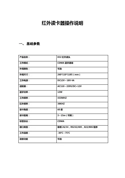
红外读卡器操作说明一、基础参数二、接线定义SW0-1:ON:入口 OFF:出口SW0-234:2代表4号地址 3代表2号地址 4代表1号地址SW1-1:ON:压地感读卡 OFF:不压地感读卡SW1-2:ON:不校验有效期 OFF:822读卡器SW1-3:ON:WG34 OFF:WG26SW1-4:ON:反潜回 OFF:无反潜三、软件操作1、打开软件供应商_反潜回选择好串口(串口即选择发卡器或读卡器连接的串口,默认是打开连接COM1)2、读卡器密码的下载选择串口连接打开后,在下载区选择设置读头和发卡器密码这一项。
在串口选择的下面有个,原密码填写这个读卡器之前使用的密码(出厂默认为6个F)密码位置填写现在要使用的密码,填写好之后点击在下载区的下载按钮,在下方有提示成功或失败。
3、发卡器密码下载及卡片加密选择串口连接打开后,在下载区选择设置读头和发卡器密码这一项。
在串口选择的下面有个,原密码填写之前发卡器使用的密码(出厂默认为6个F)密码位置填写卡片之前使用的密码(卡片默认出厂为6个F)。
填写好之后点击在下载区的下载按钮,在下方有提示成功或失败。
下载完发卡器密码后在下载区选择写卡密码,在密码位置填入与之读卡器相同的密码。
点击下载,把卡片拿至距发卡器感应区10CM的位置,点击下载,在下方有提示成功或失败。
4、写卡有效期、权限卡片加密之后,选择下载区的写卡有效期、权限点击下载,在下载按键下面提示成功或者失败(有效期默认为2个月,不可更改)权限控制选择根据现场情况勾选(默认为全选)5、写挂失卡选择写挂失卡,在挂失卡号位置填入你要挂失的卡号,拿一张新卡至发卡器感应区10CM位置点下载提示下载成功,把这张卡拿到读卡器上去读一下蓝色灯闪烁但没有什么提示(播报语音、开闸等),表示挂失成功。
(注:用来挂失的卡以后只能做挂失卡使用)6、写在场或者不在场根据现场情况,当车主开车已经在场内时,在办理卡片是请写入在场标志。
反之。
UHF电子标签读写模块UHFReader86用户手册V1.10目录一、通讯接口规格 (1)二、协议描述 (1)三、数据的格式 (2)1. 上位机命令数据块 (2)2. 读写模块响应数据块 (2)四、操作命令总汇 (4)1. EPC C1 G2(ISO18000-6C)命令 (4)2. 读写模块自定义命令 (4)五、命令执行结果状态值 (5)六、电子标签返回错误代码 (9)七、标签存储区及需要注意的问题 (9)八、操作命令详细描述 (10)8.1 命令概述 (10)8.2 EPC C1G2命令 (10)8.2.1 询查标签 (10)8.2.2 读数据 (12)8.2.3 写数据 (14)8.2.4 写EPC号 (15)8.2.5 销毁标签 (15)8.2.6 设定存储区读写保护状态 (16)8.2.7 块擦除 (18)8.2.8 读保护设置(根据EPC号设定) (19)8.2.9 读保护设置(不需要EPC号) (20)8.2.10 解锁读保护 (21)8.2.11 测试标签是否被设置读保护 (21)8.2.12 EAS报警设置 (22)8.2.13 EAS报警检测 (23)8.2.14 询查单张标签 (23)8.2.15 块写命令 (23)8.2.16 读取Monza4QT工作参数 (25)8.2.17 设置Monza4QT工作参数 (26)8.2.18 指定掩码扩展读数据 (27)8.2.19 指定掩码扩展写数据 (28)8.2.20 带缓存询查 (30)8.3读写模块自定义命令 (32)8.3.1 读取读写模块信息 (32)8.3.2 设置读写模块工作频率 (33)8.3.3 设置读写模块地址 (34)8.3.4 设置读写模块询查时间 (34)8.3.5 设置串口波特率 (34)8.3.6 调整功率 (35)8.3.7蜂鸣器设置 (35)8.3.8 GPIO控制命令 (36)8.3.9 读取GPIO状态 (36)8.3.10 读写模块唯一序列号获取 (36)8.3.11 标签自定义功能设置 (37)8.3.12 设置缓存的EPC/TID长度 (37)8.3.13 获取缓存的EPC/TID长度 (37)8.3.14缓存数据获取 (38)8.3.15清缓存 (39)8.3.16 查询缓存区标签数量 (39)一、通讯接口规格读写模块通过UART或者USB接口与上位机串行通讯,按上位机的命令要求完成相应操作。
1、UHF RFID读卡实验1.1、EPC Gen2读、写标签号实验实验目的理解UHF RFID的工作原理,并掌握其与HF RFID工作原理的异同点。
掌握EPC标签号的存储区域以及结构特点。
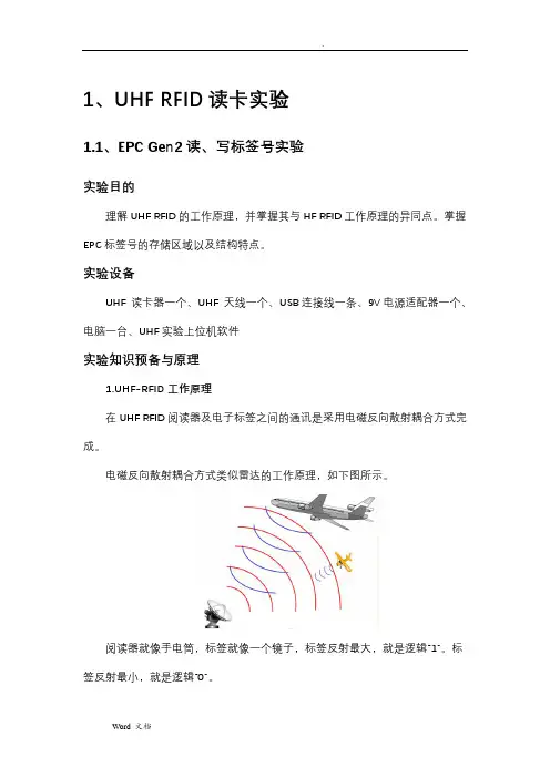
实验设备UHF 读卡器一个、UHF 天线一个、USB连接线一条、9V电源适配器一个、电脑一台、UHF实验上位机软件实验知识预备与原理1.UHF-RFID工作原理在UHF RFID阅读器及电子标签之间的通讯是采用电磁反向散射耦合方式完成。
电磁反向散射耦合方式类似雷达的工作原理,如下图所示。
阅读器就像手电筒,标签就像一个镜子,标签反射最大,就是逻辑“1”。
标签反射最小,就是逻辑“0”。
阅读器开始工作之后,通过天线先向空间发送860~960 MHz频率范围的载波,激活标签,然后开始发送带调制的命令信息到标签(TAG),可以采用ASK 调制,脉冲间隔编码(Pulse Interval Encoding),通讯速率26.7到128 KBIT/S。
在高频范围内的标签收到阅读器发出的高频载波信号,标签天线接收到特定的电磁波,天线就会产生感应电流,在经过整流电路时,激活电路上的微型开关,给标签供电。
标签上的电子线路,将根据阅读器发出信息,通过ASK或者PSK 耦合方式进行调制,FM0等编码方式,向阅读器反馈相关信息。
UHF标签电路采用ASK和PSK的调制方式,将编码信息发送给阅读器,实现了阅读器和标签之间的双向通讯。
相互认证通过之后,阅读器会向电子标签发出读、写、锁定、kill、盘存等操作指令。
2.EPC编码产品电子代码(EPC编码)是国际条码组织推出的新一代产品编码体系,原来的产品条码仅是对产品分类的编码,EPC码是对每个单品都赋予一个全球唯一编码,EPC编码96位(二进制)方式的编码体系,可以为2.68亿公司赋码,每个公司可以由1600万产品分类,每类产品有680亿的独立产品编码,形象的说可以为地球上的每一粒大米赋一个唯一的编码。
ISO18000-6C(EPC GEN2)与ISO18000-6B的详细区别是以下几点:1.ISO18000-6B一次最多可以读取10个标签,用户数据区较大,数据传输速率40Kbps左右,一般用于资产管理领域。
2.EPC C1G2即ISO18000-6C,可同时读取数百个标签,用户数据区较小,数据传输速率在40Kbps-640Kbps,通常用于物流管理。
6C的成功点是将无源标签的空中数据帧剪短了,是一种典型的短帧通讯方式,这样一来,只要瞬间构成标签与读写器天线之间的无线电能量传递条件即可高效率地完成通讯,因此识别率比早期的无源标签有很大提高。
配合多群组识别,防冲撞机制,密集读写器方式,透明ID及私有数据区等功能,为以物流为代表的广泛应用提供了一种有效的非接触识别手段。
6C是有私有数据区的。
简单说,只有百万级以上用户才有资格在订货时选择私有数据区,这也是6C针对海量应用的一种市场策略,以此筛选掉不经济的应用(供求双方均不经济)。
常规应用中,可以通过Access,Kill两个控制字的锁定保护这个数据区,一旦锁定在没有控制字的条件下是看不到的,也读不出来,除非知道AccessPWD。
而KillPWD有32bits,配合32bits的AccessPWD作防伪已经足够了。
街上很多混市的标签高喊自己是Gen2,实际仅仅是6C的ID而已,根本不能提供Gen2的全部功能,特别是那些优秀功能,读写器也是如此。
Gen2中有64Byties的用户私有数据区,对于百万以上的用户,这个区域的每一个byte都是可以锁定的,可以只读,可以读写,还可以在没有密钥的情况下禁止读出。
很理想的产品。
----如果非要说6C与Gen2的关系,明确地讲,6C是Gen2的子集。
Gen2有的功能和可扩展性6C可能没有。
UHFRFID读写器的工作频率及作用介绍
RFID电子标签的工作频率是其重要的特点之一,按照频率的不同分为低频(LF)、高频(HF)、超高频(UHF),不同频率的电子标签特点不同,被应用在不同的领域。
UHF RFID读写器是工作于超高频(UHF)频段的射频识别设备,用来读取超高频电子标签,频率范围在860~960 MHz,超高频电子标签主要应用在仓储物流、车辆识别、服装管理等领域。
UHF RFID读写器的读写距离远,读取距离与读写器模块的性能、天线的增益、标签的尺寸有关,同时也受到环境因素的影响。
UHF RFID读写器可实现多标签读取,常用UHF RFID读写器形式可分为手持式RFID读写器的和固定式RFID读写器。
在工作时,UHF RFID读写器发出查询信号,标签收到后,将信号的一部分能量用于标签内部工作电源,另一部分信号经过标签内部电路调制后反射回UHF RFID读写器。
UHF RFID读写器应用在仓储出入管理
面对大批量货物流动时,相较于需逐一采集的条码技术,RFID技术应用可实现批量读取。
在龙门架或者其他装置上进行部署UHF RFID 读写器,可对进出车辆及其搭载的货物与系统任务单进行校对,确保货物移动安全的同时,节省人力及盘点时间,高效完成货物清点。
BU-900M-K小型900M读卡控制一体机使用说明书2010-A目录第1章概述 (4)外观及指示 (4)接口面板 (4)第2章联网及控制功能 (6)第3章光耦输入 (7)第4章继电器输出 (7)控制道闸抬杆 (7)外接高电压大功率负载(100W灯泡) (7)第5章性能指标 (9)第6章常见故障处理 (10)第7章注意事项 (10)第8章随机文件及附件 (10)第9章售后服务 (11)声明此为A级产品,在生活环境中,该产品可能会造成无线电干扰。
在这种情况下,可能需要用户对其干扰采取切实可行的措施。
读卡时,人员应该至少离开天线30cm,才能满足美国FCC要求的最大允许的人体射频(RF)辐射条款要求。
第1章概述小型900M读卡控制一体机(型号为BU-900M-K)是本公司自主研发的高端UHF RFID 读卡控制器,具备远距离读卡和输出控制信号两大功能。
BU-900M-K读卡控制器可以读写符合EPC Gen2标准的“电子标签”,同时还能兼容2.4G有源标签。
电子标签被附着在待识别的物品表面,电子标签中保存了用于标识物品的电子信息。
BU-900M-K在一定区域内发射无线电信号,形成一个有效的电磁场,电子标签通过这个区域时将被激活,经过必要的握手后向读卡器发送存储在标签中的电子信息。
BU-900M-K在联网情况下会把读卡记录和时间传送到上位机系统,脱机情况下则会保存本次读卡记录。
BU-900M-K读卡控制器广泛适用于门禁型停车场系统管理、不停车自动收费(ETC)、人员门禁管理、电子防伪、物流监控、生产自动化管理等数据采集系统。
外观及指示BU-900M-K读卡控制器把传统的天线、读写器有机的融合到一起,结构紧凑,免除了施工时布设高频同轴线的麻烦。
读卡器外形如下图:天线面板的正下方,有一个红色和四个蓝色的LED指示灯,根据读卡器工作的状态不同会有不同的反应:最左边为红色电源指示灯;右边四盏蓝色LED在读到卡片时高亮闪烁,并伴有蜂鸣器鸣叫;此四盏蓝灯复合噪声指示功能,在探卡过程中能指示出环境干扰的强度,不亮为最小,全亮为环境干扰恶劣。
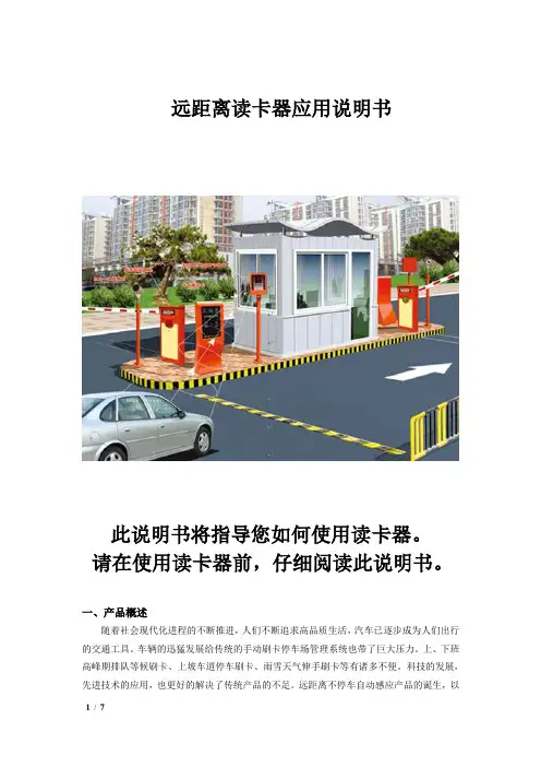
远距离读卡器应用说明书此说明书将指导您如何使用读卡器。
请在使用读卡器前,仔细阅读此说明书。
一、产品概述随着社会现代化进程的不断推进,人们不断追求高品质生活,汽车已逐步成为人们出行的交通工具。
车辆的迅猛发展给传统的手动刷卡停车场管理系统也带了巨大压力。
上、下班高峰期排队等候刷卡、上坡车道停车刷卡、雨雪天气伸手刷卡等有诸多不便。
科技的发展,先进技术的应用,也更好的解决了传统产品的不足。
远距离不停车自动感应产品的诞生,以便捷、减排、省时、节油等传统产品无法比拟的优势,将全面取代传统式手工刷卡的停车场系统。
因停车场系统应用的特殊性,并不是任何一款远距离读卡设备都能发挥应有的功能,在实际应用中信号能否穿透汽车隔热膜、相临车道信号干扰、跟车信号干扰、微波辐射危害、信号衰减、电磁兼容等关键技术成为产品稳定性的重要因素。
我公司生产的定向远距离读卡器利用红外和微波同步通讯技术,充分考虑产品在停车场系统和ETC系统应用的特点,是国内目前唯一能解决准确定位和互相干扰的远距离读卡设备。
二、系统原理该款远距离定向读卡器结合了红外与射频通讯特点,互补两个不同频率通道的工作优势,相互进行信息传递。
射频是一个无方向的电磁波,难以准确定向,但通讯速度快;而红外具有严格的角度定位,但通讯速度慢;在停车场实际应用中选用某一个通道通讯难以达到理想的使用要求。
原理:读卡器发射60度红外扫描信号,红外信号是经过加密的数据,包含了唤醒编码、机器编码信息;当休眠中的远距离卡进入读卡器发送的红外信号范围时,立即被唤醒工作,发射射频电磁波发送远距离卡内码,在发送卡内码的同时也将读卡器机器码附带传递给读卡器;读卡器接收到卡号后对首先对机器码验证,与该机身码相符的为有效卡直接上传给上位机,与该机器码不符的直接删除,避免了临近车道和跟车的串号干扰。
红外信号扫描范围远距离读卡器休眠中的远距离卡三、产品特点⑴穿透性:可穿透任何金属汽车防爆膜,远距离卡放置到车内,无需摇窗户可自动识别感应;⑵方向性:采用红外定位射频传输双通道模式方式工作,具有严格的方向性和稳定性,读卡区60度以外绝不读卡。
UHF电子标签读写器LJYZN-RFID101用户手册v2.0目录一、通讯接口规格 (4)二、协议描述 (4)三、数据的格式 (5)1. 上位机命令数据块 (5)2. 读写器响应数据块 (5)四、操作命令总汇 (6)1. EPC C1 G2(ISO18000-6C)命令 (6)2. 18000-6B命令 (7)3. 读写器自定义命令 (7)五、命令执行结果状态值 (8)六、电子标签返回错误代码 (12)七、标签存储区及需要注意的问题 (12)八、操作命令详细描述 (13)8.1 命令概述 (13)8.2 EPC C1G2命令 (13)8.2.1 询查标签 (13)8.2.2 读数据 (14)8.2.3 写数据 (15)8.2.4 写EPC号 (16)8.2.5 销毁标签 (17)8.2.6 设定存储区读写保护状态 (18)8.2.7 块擦除 (20)8.2.8 读保护设置(根据EPC号设定) (21)8.2.9 读保护设定(不需要EPC号) (21)8.2.10 解锁读保护 (22)8.2.11 测试标签是否被设置读保护 (22)8.2.12 EAS报警设置 (23)8.2.13 EAS报警检测 (24)8.2.14 user区块锁 (24)8.2.15 询查单张标签 (25)8.2.16 块写命令 (26)8.3 18000-6B命令 (27)8.3.1寻查命令(单张) (27)8.3.2 按条件寻查标签 (27)8.3.3 读数据 (28)8.3.4 写数据 (29)8.3.5 锁定检测 (29)8.3.6 锁定 (30)8.4读写器自定义命令 (30)8.4.1 读取读写器信息 (30)8.4.2 设置读写器工作频率 (31)8.4.3 设置读写器地址 (32)8.4.4 设置读写器询查时间 (32)8.4.5 设置串口波特率 (32)8.4.6 调整功率 (33)8.4.7 声光控制命令 (33)8.4.8韦根参数设置命令 (34)8.4.9工作模式设置命令 (34)8.4.10读取工作模式参数 (36)8.4.11 EAS检测精度设置 (37)8.4.12 Syris响应偏置时间设置 (37)8.4.13 触发延时设置 (38)一、通讯接口规格读写器通过RS232或者RS485接口与上位机串行通讯,按上位机的命令要求完成相应操作。
RFID读写应用程序说明RFID读写器应用程序是为用户了解RFID的功能及操作命令而编写的程序。
用户通过本程序对卡片进行操作,可熟悉ISO 15693标准及其操作。
对RFID卡的应用有一个清楚地了解。
一、内容说明1)本子目录中包括RFID读写器在PC机上读写应用程序。
2)用户在PC机WINDOWS系统中安装该程序后可完成由RFID卡的所有操作。
3)用户通过该程序的使用,可以熟悉RFID卡的操作,从而为自己的进一步应用作好准备。
4)该应用程序是用VB6.0语言编译而成。
用户如需要其源代码,可向供货商查询。
二、安装说明1)将文件拷贝到硬盘后,运行SETUP,直接按照系统提示进行安装。
三、操作说明本应用程序采用WINDOWS结构,提供了对RFID卡操作的所有命令的功能按键。
用户点击各功能按键,即可完成相关的操作。
以下详细说明各个功能键的使用,以及其所需参数说明。
在RFID读写器中提供三类命令,分别为:1)RFID读写器系统命令:该命令集提供可控制读写器状态及LED、蜂鸣器操作的命令。
2)ISO15693标准基础命令集:该命令集提供针对ISO15693标准的所有基础命令集的操作。
3)厂商专用命令集:根据ISO15693标准,各厂商提供的卡片操作除符合ISO 15693的基础命令集完,还可根据自己的定义,提供各具特色的只符合其厂商卡片的专用命令集。
在RFID读写器中,为方便用户使用,我们将PHILIPS公司、TI公司、INFINION公司的卡片专用命令集分别提供,用户可以根据自己的卡片,直接对相关卡片进行操作。
四)RFID读写器系统命令RFID读写器提供如下系统操作命令:. 联接. 操作模式. 厂商命令选择. 读版本号. 灯控. 断开联接1)“联接”在执行其他命令前,必须先执行“联接”命令,打开串行口。
在该命令中,是采用“自动联接”功能,程序自动查询COM1或COM2口,判别是否己联接RFID读写器,如联接成功,则所有的其他功能键均有效,用户可进一步运行其他的命令。
RFID设备操作使用说明RFID(Radio Frequency IDentification)即射频识别技术,又称电子标签、无线射频识别,是一种通信技术,可通过无线电讯号识别特定目标并读写相关数据,无需识别系统与特定目标之前建立机械或光学接触。
一套完整的RFID系统,是由阅读器(即手持终端或桌面式终端)与电子标签及应用软件系统三个部分所组成,其工作原理是阅读器发射一特定频率的无线电波能量给电子标签用以驱动电子标签电路将内部的数据送出,此时阅读器便依序接收解读数据,送给应用程序做相应的处理。
本次购买的两套设备均为深圳市溪源尔科技有限公司的产品,分别为E9900U超高频手持机及RFID桌面式超高频发卡器。
但所购买的手持终端机功能进行了裁剪,只具有UHF RFID识别及WIFI功能。
下面讲解下两套设备的使用:E9900U超高频手持终端机注:关于手持机快捷键的一些说明:左右两侧的黄色按键是显示桌面的功能,键盘上黄色按键是二维扫描的快捷键,F2键是打开二维应用程序的快捷键1.开关机长按手持机键盘右下角的红色小按键3秒开机,再次长按关机。
2.触摸笔校准在桌面上找到“我的设备”,打开“我的设备”->“控制面板”->“笔针”,出现以下触摸笔校准界面选择“校准”点击“再校准”。
用触摸笔依次点击十字光标进行校准。
最后再点击一下屏幕或者按一下”OK”键保存设置。
3.查看内存和Nandflash 空间大小“我的设备”->控制面板->系统。
可以看到剩余内存为191132KB 约187M。
其余内存为系统运行所需内存。
查看NandFlash 空间大小。
找到nandflash 右键->属性或者“我的设备”->控制面板->存储管理器如下图:4.电池检测在桌面上找到“我的设备”,打开“我的设备”->“控制面板”->“电源”,弹出电源属性对话框,显示电池电量如图:充电用AC电源线,连上设备后,手持机屏幕上的右上角,充电电源指示灯,红灯亮,桌面任务栏上显示充电图标;如下:5.手持机与计算机通信5.1 安装USB同步驱动系统在启动后,在USB数据线连接PC的状态下,本设备将作为从设备,被PC监测到,如果没有安装USB同步驱动,PC端自动发现新硬件,并要求安装USB同步驱动,要使本设备与PC通信,需安装:1、USB同步驱动2、Microsoft ActiveSync4.5 同步软件下面介绍详细安装步骤:选择在这些位置上搜索最近驱动程序浏览:找到我们发给你的驱动选择USB同步驱动选择下一步5.2 安装Microsoft ActiveSync4.5 同步软件6.UHF 模块的使用1. 基本操作1.1读915M 卡号启动手持机,找到并打开我的设备\NandFlash\Powercontrol.exe 如图1所示:打开RFID_915(UHF模块)的电源,如图2所示图1 图2关闭Powercontrol.exe应用程序,打开UHF02_Demo.exe程序,点击打开串口,提示打开串口成功即可,如图3图3选择UHF02_Demo应用程序的“盘存”选项卡点击单步识别按钮,进行读卡操作,将卡置于合适的位置上,就可以读到卡号(标签ID)了。
第一章快速指导1.1产品概述UHF RFID手持机是一款基于WINCE 6.0操作系统的手持式读写器,支持ISO18000-6C(EPC C1 G2)协议,读卡距离可达7米;可通过USB接口与PC机交换同步数据,实现实时通讯,最高支持32G的Micro SD(T-Flash)卡扩展;具有防掉电数据安全保护,在完全掉电情况下数据不丢失.产品应用:♦仓库物流,资产,畜牧业,图书,门票,门禁,集装箱等领域;需要移动采集数据的各种场合产品特点:♦支持EPC Class1 Gen2/ISO18000-6C;♦输出功率软件可调,10dBm~28dBm,1dBm步进;♦读取距离可达7米(标签为UPM SHORTDIPOLE_M3);♦4小时以上连续工作时间,待机约20天♦人体工学设计手柄,减轻使用疲劳感性能指标性能参数处理器ARM11, 667MHz内存容量128MB SDRAM,256MB NAND-Flash操作系统WINCE6.0无线通讯WIFI符合IEEE 802.11b/g蓝牙(选配)符合Bluetooth 2.1+规范GPRS(选配)支持(900、1800MHZ)广域无线通讯显示屏 3.2英寸,分辨率240*320,工业TFT液晶屏,带触摸存储卡最大支持32G Micro SD卡电池锂聚合物可充电电池,3500mAh,7.4V工作时间连续读卡约4小时条码模组一维模组(标配),二维模组(选配)拓展模组GPRS模组(选配),GPS模组(选配),2.4G模组(选配) 指示灯网络指示灯,电源指示灯键盘27键输入音频1524大喇叭通讯接口USB SlaveRFID参数支持协议EPC Class1 Gen (ISO18000-6C)频率中国:920MHz~925MHz北美:902MHz~928MHz(默认)欧洲:865MHz~868MHz可定制频率范围:860MHz~960MHz 读取距离最大7M(与标签有关)写入距离最大3M(与标签有关)物理参数外形尺寸81*183*150mm整机重量 1.115kg(含充电底座)环境参数工作温度-20℃~50℃存储温度-20℃~70℃存储湿度5%~95%无凝露防护等级IP65手持机侧面示意图1616134 5 678910111214 13 1项 目 数量 备 注 主机 1 UHF RFID 手持机触屏笔 1 带弹簧绳USB 线 1 USB 转Micro 5pin提示对话框 长按开手持机开/关机键充电芯片图1.2双击手持机电池电量图标进入到电池属性界面,在此界面可以查看当前剩余电量及充电状态;如下图1.3所示:图2.3”选项→单击“重新安装驱动程序”按钮→勾选“从列表或指定位置安装”选项再单2.4图3.2电源打开后;手持机主界面→点击“系统”图标图5.1 图5.2附录二保养维护♦请勿在有腐蚀性的环境中使用终端;♦请勿让终端高空跌落或受到强烈撞击;♦在装SIM卡时建议让手持机处于关机状态;♦勿使用尖锐的东西触碰屏幕,以免对屏幕造成损坏;♦如屏幕表面肮脏,可使用软布沾稀释的屏幕清洁剂进行清洁;♦请勿将终端存放在阳光直接照射、湿度极高和靠近热源的位置;♦请勿使用非本设备专用的电池充电器及电池,以免对设备造成损坏;♦按照规定弃置使用过的锂离子电池。
1、UHF RFID读卡实验1.1、EPC Gen2读、写标签号实验实验目的理解UHF RFID的工作原理,并掌握其与HF RFID工作原理的异同点。
掌握EPC标签号的存储区域以及结构特点。
实验设备UHF 读卡器一个、UHF 天线一个、USB连接线一条、9V电源适配器一个、电脑一台、UHF实验上位机软件实验知识预备与原理1.UHF-RFID工作原理在UHF RFID阅读器及电子标签之间的通讯是采用电磁反向散射耦合方式完成。
电磁反向散射耦合方式类似雷达的工作原理,如下图所示。
阅读器就像手电筒,标签就像一个镜子,标签反射最大,就是逻辑“1”。
标签反射最小,就是逻辑“0”。
阅读器开始工作之后,通过天线先向空间发送860~960 MHz频率范围的载波,激活标签,然后开始发送带调制的命令信息到标签(TAG),可以采用ASK 调制,脉冲间隔编码(Pulse Interval Encoding),通讯速率26.7到128 KBIT/S。
在高频范围内的标签收到阅读器发出的高频载波信号,标签天线接收到特定的电磁波,天线就会产生感应电流,在经过整流电路时,激活电路上的微型开关,给标签供电。
标签上的电子线路,将根据阅读器发出信息,通过ASK或者PSK 耦合方式进行调制,FM0等编码方式,向阅读器反馈相关信息。
UHF标签电路采用ASK和PSK的调制方式,将编码信息发送给阅读器,实现了阅读器和标签之间的双向通讯。
相互认证通过之后,阅读器会向电子标签发出读、写、锁定、kill、盘存等操作指令。
2.EPC编码产品电子代码(EPC编码)是国际条码组织推出的新一代产品编码体系,原来的产品条码仅是对产品分类的编码,EPC码是对每个单品都赋予一个全球唯一编码,EPC编码96位(二进制)方式的编码体系,可以为2.68亿公司赋码,每个公司可以由1600万产品分类,每类产品有680亿的独立产品编码,形象的说可以为地球上的每一粒大米赋一个唯一的编码。
UHF模块通信协议说明书1.通信协议结构 (1)1.1物理层 (2)1.2 数据链路层 (2)2.命令帧定义 (3)2.1系统设置命令 (3)2.2 ISO18000-6B标签操作命令 (4)2.3 EPC GEN2标签操作命令 (6)2.4 缓存管理命令 (8)3.技术支持 (9)4,附录:命令索引表 (9)一:模块说明引脚 1 2 3 4 5 6定义 VCC3.7V—4.2V GND TX(TTL)RX(TTL)GND指示信号(3.3V)高电平有效二:通信协议设计说明通信协议指PC机通过USB或者RS-232通信接口操作读写器的通信规约。
通信协议采用面向字节的异步通信协议数据格式。
规定PC机发给读写器的数据帧为命令,读写器返回给PC机的数据帧为响应。
命令或响应数据帧是变长字节数,采用组包方法并用校验和方法进行后向检错。
命令或响应数据帧最长为128字节。
1 通信协议结构通信协议采用如下图的层次结构,包括物理层、数据链路层和应用层。
图1:通信协议结构图1.1物理层物理层完成信号的比特数据发送与接收,物理层应符合RS-232规范要求。
具体设计要求如下:z1位起始位、8位数据位、1位停止位、无奇偶校验;z通信波特率设计为9600bps、19200bps、38400bps、57600bps、115200bps可选。
读写器上电或复位后初始波特率为9600bps,可由PC机发送命令改变读写器通信波特率。
当PC机与读写器传输发生错误时,读写器波特率回复为9600bps。
1.2 数据链路层数据链路层具体规定命令和响应帧的类型和数据格式。
帧类型分为命令帧、响应帧、读写器命令完成响应帧。
1.2.1 命令帧格式定义命令帧是主机操作读写器的数据帧,格式如下表所示:Head Addr Len Cmd Parameter… Parameter Check 0x0A 1 byte n+2 1 byte Byte 1 Byte n cc z Head是帧头标志,定义为0x0Az Addr是读写器地址,一般地址从0~240,255(0xFF)为公用地址,254(0xFE)为广播地址。
JT-907 远距离超高频模块
产品特点
◆符合EPC C1 GEN2 ( ISO 18000-6C) 标准
◆读取距离可达6米(外接7dbi天线,标签为UPM
SHORTDIPOLE_M3 )
◆优异的读写性能及防冲撞能力
◆全球多频率标准支持
◆良好的散热效果、确保设备稳定性产品介绍
JT-907为一款低成本、高性能超高频电子标签读写器模块,具有完全的自主知识产权,该读写器模块默认工作频段为902MHz~928MHz,在标准7dBi的天线及相应标签配合下,读取距离可达6米,配合简单的供电及接口电路,可迅速搭建低成本的RFID识别系统。
适用于物流、服装、资产管理等复杂应用环境。
产品应用
◆仓储物流管理
◆生产流程控制
◆资产管理
◆RFID嵌入式系统集成
外观结构
JT-907射频模块外观结构如下所示:
接口描述如下图所示
接脚定义
ATMEL_RXD1
CON16 ATMEL_TXD1
结构尺寸安装示意图(mm):。