新版DSET工具的使用说明 5
- 格式:doc
- 大小:173.50 KB
- 文档页数:3

DellSystemE-SupportTool(DSET)⼯具使⽤⽅法前⼏天我们公司的⼀个服务器宕机了,ping不通ssh连不上。
只好让IDC机房⼯作⼈员帮我们重启我们的服务器。
重启完之后赶紧查看⽇志,但是⾃⾝服务⽇志并没有报错。
接下来就是分析硬件问题了。
我们服务器是DELL的,经理让我安装了⼀个DELL 的检测⼯具。
Dell System E-Support Tool (DSET)这个⼯具可以⽤来收集服务器硬件信息,存储信息(RAID卡,硬盘等)。
及linux 驱动,服务,⽹络设置等等,同时⼜包括CPU,memory, ESM log, BIOS/firmware versions and system health (fan/voltage levels).安装步骤1 授予权限执⾏这个可执⾏⽂件[root@www ~]# chmod +x delldset_v2.2.0.122_x64-A00.bin[root@www ~]# ./delldset_v2.2.0.122_x64-A00.bin。
PARTICULAR PURPOSE, TITLE AND ANY WARRANTY OF NON-INFRINGEMENT. YOU WILLUSE THE SOFTWARE AT YOUR OWN RISK. DELL SHALL NOT BE LIABLE TO YOU FOR ANYDIRECT OR INDIRECT DAMAGES INCURRED IN USING THE SOFTWARE. IN NO EVENT SHALLDELL OR ITS SUPPLIERS BE RESPONSIBLE FOR ANY DIRECT OR INDIRECT DAMAGESDell License (42%): Press spacebar to view next page, 'q' to proceed2,按q之后出现是否接受协议,直接按yDELL OR ITS SUPPLIERS BE RESPONSIBLE FOR ANY DIRECT OR INDIRECT DAMAGESDo you accept the terms of this license? (y/n):3,按y之后出现如下提⽰Dell System E-Support Tool (DSET) Options:Choose an option:1) Read DSET Release Notes FirstShow latest information concerning features and known issues2) Create DSET Report OnlyCreates a DSET report and saves it to user's home directory3) Clear ESM Hardware Log OnlyOnly clears the ESM Hardware Log contents4) Install/Upgrade DSET ApplicationPermanently installs or upgrades the DSET application for repeat useEnter option (1-4) or 'q' to quit:4,选4安装Install Location:Where should DSET be installed?Default location: /opt/dell/dset //默认程序安装位置Press Return to accept the default location orenter a new directory path:Directory does not exist. Create? (y/n): yPreparing... ########################################### [100%]1:delldset ########################################### [100%]Installation of Dell System E-Support Tool (DSET) complete.Enter 'dellsysteminfo' from a terminal shell prompt to create a report file.5,查看帮助[root@www ~]# dellsysteminfo -hDell System E-Support Tool@Copyright Dell Inc. 2004-2008 Version 1.6 build 135The given option is invalid: ['-h']Usage: dellsysteminfo [-options] [-f filepath/filename]Options:-f Specify a filename, a path using default filename, or both--nohardware Skips collecting info for all hardware categories--nostorage Skips collecting info for all storage categories--nosoftware Skips collecting info for all software categories--nologs Skips collecting any non-Linux log files--time Append report filename with timestamp--silent Accept defaults and prevent user prompting (for scripting)--advanced Collect various advanced logs (may create large report size!)6 获取系统报告,-f 指定报告位置在/home/report.zip,这⾥会等⼀段时间,这是他正在检测系统硬件系统,存储系统和操作系统信息,检测完,/home/⽬录下回产⽣⼀个report.zip 就是我们要的报告[root@bogon ~]#dellsysteminfo -f /home/report7 查看报告内容。

SSD铁舾件设计系统操作使用说明书上海东欣软件工程有限公司二ΟΟ六年八月目录1标准部件输入 (2)2铁舾件处理 (3)2.1安装铁舾件操作 (3)2.2制作钢板并安装操作 (4)2.3修改铁舾件操作 (4)2.3.1重命名铁舾件操作 (4)2.3.2移动铁舾件操作 (5)2.3.3复制铁舾件操作 (5)2.3.4旋转铁舾件操作 (5)2.3.5伸缩型材操作 (5)2.3.6翻转型材操作 (5)2.3.7替换型材操作 (5)2.3.8修改参数操作 (5)2.3.9修改材质操作 (6)2.4删除铁舾件操作 (6)2.5标准模型库存取操作 (6)2.6材料清单生成操作 (6)3零件和托盘处理 (7)3.1铁舾件托盘建立 (7)3.2铁舾件零件处理 (7)3.3铁舾件托盘处理 (7)4图纸处理 (8)4.1铁舾件制作图生成 (8)4.2图号管理、图纸输出和图面处理 (8)5生产用表处理 (9)5.1铁舾件制作图生成 (9)5.2查看输出文件夹 (9)1 标准部件输入在启动界面上点击参数化标准部件按扭,则可以将参数化部件库(data/hdssd.pam)中的参数化铁舾件的参数标准化,以部件代号作为选择的标示保存在标准数据库(data/vspd_std)和实体部件库(data/myspd.pel)中,以备交互布置时使用。
标准部件输入对话框如下:在标准部件输入对话框中先选择大类,确定大类后,再选择小类,然后再选择参数类型。
选择相关的工程目录,则保存到工程部件库(工程编号.PEL)中,如果要保存到系统部件库(myspd.PEL)中,则选择EFCSD目录即可。
在下面的表格中输入部件代号以及与该代号相关联的参数值,点击保存按扭即可。
参数名称的意义可查看PPD.exe。
如需要输入多行标准部件,点击添加按钮,系统自动增加部件输入的空白项,供用户进行部件的输入。
如果要删除部件,只要删除该部件代号,然后再按保存按钮即可。
如果要修改表格中内容,直接在表格中修改,修改好后点击保存按钮即可。
CSS5-04-1-服务工具使用手册产品管理DCSS 5服务工具使用手册BD11 IVa Vintage : 014.1状态显示(键311)14 4.2输入状态显示(键312)15 4.3输出状态显示(键313)184.4指令状态显示(键314)195 测试功能(键32)20 5.1 事件菜单显示(键321)205.1.1 实际显示(键:3211)205.1.2事件记录显示(键3212)225.1.3历史显示(键3213)225.1.4删除显示(键3219)23 5.2维护(键322)24 5.3部件号(键323)24 5.4接口检查(键324)24 5.5系统配置(键325)26 6设置功能(键33)266.1 首次安装预置曲线1 (键331) 286.1.1配置(键3311)296.1.2设置缺省(键3319)38 6.2首次安装预置曲线2(键332)39 6.3参数设置—现场--(键333)40 6.4参数的设置--工程--(键334)42 7工具(键34)437.1单一指令(键341)43 7.2连续指令(键342)44 7.3 ADAM(键343)44产品管理DCSS 5服务工具使用手册BD11 IVa Vintage : 011 显示器与键的排列服务工具前控制面板由双行显示,每行16字符和16个键。
有些键有第二个功能,它可以先按兰色按钮再按此键来启动,占用键的排列如下所示:2 与 DCSS 连接与任何子系统连接时,服务工具可引导自测,然后执行设置程序。
在与任一子系统建立正确通信时,各种显示在后面各章节中介绍.产品管理DCSS 5服务工具使用手册BD11 IVa Vintage : 013.2 键功能综述服务工具前控制面板由2行显示组成,每行16个字符,且有16个键。
有些键有第二个功能(用兰色标记),按SHIFT键可以启动该功能(先按SET键下面无标记兰色键)然后再按所需的功能键.模块(MODULE):可导向至顶层菜单,轿厢门铃控制辅助系统DCSS欢迎信息--中断自动安装.功能(FUNCTION):可导向至第二层菜单,在自动安装时无效.设定(SET):自子菜单返回所有权菜单级。
数据安全专家(DSE)企业版快速使用手册1文档概要1.1目的根据软件的各种应用场景,提供具体的使用说明,方便管理员快速使用和熟悉DSE软件。
2 使用说明2.1登陆控制台管理员双击桌面快捷图标启动DSE控制台,管理员登录控制台时,需输入DSE服务器的IP地址和端口,默认端口:5558,默认用户名为:“admin”,密码“Admin@123”(注意:字母大小写敏感),具体操作界面如下所示:图2-1 控制台登陆控制台登陆以后主界面如下:图2-2 DSE主界面首次安装,客户端默认在根组“Computer Root”下面,并继承根组的设置。
2.2设置文件自动透明加解密登陆控制台,切换到“计算机管理”中的->文件加密策略:图2-3 文件加密策略首次安装完成,默认提供word,excel,ppt三种进程的自动透明加解密,安装成功并在线的客户端机器,新建或编辑word,excel,ppt时便会自动加密,文件加密以后,文件图标上自动显示盾牌的加密图标,以示为加密文件。
您可以点击上图中的“增加”按钮,授权新的加密进程,点增加弹出如下界面:图2-4增加加密进程列表中提供常用的加密程序,选中需要加密的进程,确定,即可添加成功。
下发策略,授权的加密进程重新启动后生效。
2.3 文件加密策略中的基本策略设置2.3.1根据单个进程设置是否允许打印选中图2-3中的“已授权加密程序列表”中的单个进程,双击或点“修改”,弹出修改加密程序策略界面,如下图所示:图2-5修改加密程序策略建议使用系统默认配置策略,无需修改,默认策略是最安全的加密策略,如需针对单个进程允许打印,勾选“允许打印”,还可以设置打印水印。
勾选对应选项,确定,下发策略生效。
2.3.2全局策略设置(禁止截屏、控制剪贴板等)图2-3中页面下方的基本策略,是针对所有加密进程的全局策略,建议使用默认配置,如下图所示:图2-6基本策略您可以根据需要启用和禁用相应的策略,勾选即为启用,不勾选为禁用;保存下发策略生效。
TDSV系列数字式交流伺服驱动器使用说明书北京西贝通达科技有限公司V1.2 Build 1522010年09月目录1概要 (1)2安全、正确使用规定 (2)2.1一般说明 (2)2.2防止触电伤害注意事项 (2)2.3防止损伤及设备损坏注意事项 (2)2.4防止火灾注意事项 (3)2.5其他注意事项 (3)2.5.1环境要求 (3)2.5.2安装及连接 (3)2.5.3运行 (4)3型号名称及技术规格 (6)3.1驱动器型号名称 (6)3.2技术规格 (6)4安装 (8)5信号与连接 (9)5.1信号定义 (9)5.1.1主回路强电端子 (9)5.1.2编码器反馈插头--CN1 (11)5.1.3控制信号插头—CN2 (12)5.1.4通讯插头—CN3 (17)5.2典型外部连接 (18)5.2.1主电路强电连接 (18)5.2.2模拟速度控制信号连接 (19)5.2.3模拟力矩控制信号连接 (20)5.2.4通讯接口信号连接 (20)6参数说明 (21)6.1参数设定及调整方法 (21)6.2参数的初始调整 (21)6.2.1电机参数的调整 (21)6.2.2运行方式参数的调整 (21)6.2.3控制回路调节参数的调整 (22)6.2.4专用功能参数的调整 (22)6.2.5通讯控制参数的调整 (22)6.3参数说明 (23)6.3.1电机参数 (23)6.3.2运行方式设定参数 (24)6.3.3运行指令参数 (31)6.3.4控制调节器参数 (35)6.3.6监视参数 (44)6.3.7专用功能设定参数 (49)6.3.7.1定位功能设定参数 (49)6.3.7.2摆动及切换变速比功能设定参数 (53)6.3.7.3模拟量刚性攻丝功能设定参数 (55)6.3.7.4模拟量铰孔功能设定参数 (56)6.3.7.5脉冲位置控制功能(C轴功能)设定参数 (57)6.3.8通讯参数 (59)6.4参数总表 (60)7操作面板 (68)7.1概述 (68)7.1.1指示灯状态及功能 (68)7.1.2按键功能 (68)7.1.3上电初始状态 (69)7.2数码管显示模式 (69)7.2.1数码管主菜单显示模式 (69)7.2.2参数管理模式子菜单显示 (69)7.2.3监控模式子菜单显示 (69)7.2.4辅助功能模式子菜单显示 (70)7.3参数管理模式 (71)7.3.1读取参数值 (71)7.3.2修改参数值 (71)7.3.3快速切换参数号 (72)7.4监控模式 (72)7.4.1切换监控参数 (72)7.4.2显示监控参数值 (73)7.5辅助功能模式 (73)7.5.1试运行电机 (73)7.5.2报警追踪 (74)7.5.3密码权限 (75)8TMS-WIN监控软件 (77)8.1概述 (77)8.2状态监控界面 (77)8.2.1驱动器工作状态 (78)8.2.2驱动器实时数据 (78)8.2.3电机控制 (79)8.2.4工具栏及状态栏 (80)8.2.5考机功能 (80)8.3参数界面 (81)8.3.1参数浏览 (81)8.3.2参数修改 (81)8.3.4I/O端口调试 (83)8.4图形界面 (84)8.4.1数据采样 (84)8.4.2图形设置 (86)8.4.3数据测量 (87)8.5用户权限 (87)8.6软件菜单 (88)9常见报警及处理方法 (91)10维护与检修 (93)10.1维护及检修内容 (93)10.2易损件更换 (94)10.3存储 (94)TDSV系列交流伺服驱动器使用说明书1概要感谢您购买TDSV系列交流伺服驱动器产品。
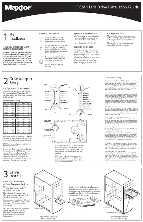
Handling PrecautionsAllow the drive to reach room temperature before installing it in the computer.Do not open the E S D bag until youÕre ready to install the drive. Handle the drive by its sides. Do not touch the circuit board (electronics). Do not connect/disconnect any drive cables while your computer is turned on.Do not drop, jar, or bump the drive.1PreIn s tallatio nT hank yo u fo r se le c ting a Maxto r hard d rive sto rag e p ro d uc t.Maxto r's g o al is to p ro vid e yo u w ith the m o st up -to -d ate p ro d uc t p o ssib le ,and w e are c o nstantly e nhanc ing o ur so ftw are and d o c um e ntatio n to b e tte r m e e t yo ur ne e d s .Ple ase visit o ur w e b -site at to vie w the late st that Maxto r has to o ffe r!System /OS Requirem ents¥ A full version of your operating system (OS) is required for a new hard drive installation(see kit package for details)Tools for InstallationThe following tools are needed to install your new M axtor hard drive:¥Small Phillips head screw driver ¥Small pair of pliers or tweezers ¥Your computer user manual ¥Operating system softwareBackup Your DataM axtor highly recommends that you make a backup copy of your files before installing the new M axtor hard drive.Please refer to your computer user manual for more information.2D r ive J um p e r S e t u p Configure the Drive J um persIf specific jumper options are needed for your system configuration, refer to the illustrations and definitions provided in this section.SCSI ID J umper SettingsM axtor SCSI drives typically ship from the factory with jumpers set to SCSI ID 6, and termination power jumped.SCSI ID 7 is usually reserved for the SCSI host adapter.3D rive InstallInstalling Drive Inside of Y our Com puter SystemM ake sure your com puter is pow ered dow n before installing the drive.The following illustrations are of typical computer systems and hard drive mounting styles.Your computer may have a different mounting style. Please refer to your computer user manual for more information.B e sure to secure the drive to the device bay with all four screws.The drive should be oriented with its printed circuit board facing down.Installing 5.25-inch Mounting BracketsIf the hard drive will be installed in a 5.25-inch device bay, attach mounting brackets (available separately) to the hard drive as shown in the figure below.Mounting ScrewsMounting ScrewsMounting BracketNote:M axtor LVD SCSI drives do not support on-board termination. M axtor recommends the use of Active LVD terminators and 68-pin twisted pair cabling.S CS I hos t adapter manufacturers us ually s upply proper cabling and termination with the purchase of an LVD S CS I hos t adapter.A ttention:The R ear J umper O ption Connector is an O E M specific con-nector. M ost installations will never use the jumper options on this connector. Always configure the drive using the jumpers at the Front J umper O ption Connector .Other J umper SettingsTP - Termination Pow er (12 Pin O ption Connector)Pins 11-12 T ermination power ensures that there is a sufficient power level along the entire SCSI bus. It is recommended that the final device on the SCSI bus have the Termination Power jumper installed. All devices in between the host and final device typically have no jumper on Termination Power.Note that Termination Power is not the same as on-board termination, which this drive does not support.S S - S tagger S pinPins 13-14 For most configurations this option is not utilized.M ost current SCSI host adapters offer a Start Unit command enable or disable, which supersedes the functionality of the SS jumper setting. W hen the Delay Spin (DS) jumper isenabled on the drive, the Start Unit command from the SCSI host adapter will send Start Unit commands to all devices on the bus at pre-determined intervals. This can help prevent power supply overload when running several devices on the SCSI bus.W P - W rite ProtectionPins 11-12 B y factory default, the drive is shipped with no jumper on these pins, and the drive can be written to unless protected by application software. W ith the pins jumped, the drive can be used as a read-only device. This feature prevents accidental overwrites and is useful for frequently accessed archives and reference files.Force S E Ð Force S ingle Ended O perationPins 17-18 By factory default, the drive is shipped with no jumper on these pins. W ith most system configurations, it is not necessary to use this jumper. LVD drives are multi-mode capable. They will automatically detect the presence of a sin-gle-ended bus and revert to single-ended mode.DS - Delay S pin Disable Delay S pin: No jumper across pins 15-16 (factory default). Disabling Delay Spin allows the drive to spin up when the system is powered up.Enable Delay S pin: J umper across pins 15-16 This setting will prevent the drive from spinning up until it receives a Start Unit command from a SCSI host adapter. M ost SCSI host adapters have the Start Unit command enabled by default in the host adapter BIOS. Enabling Delay Spin is only necessary when you are starting multiple devices at power on.S CS I IDPin numbers 1-8 are typically referred to in pairs as A0 (pins 1and 2), A1 (3,4), A2 (5,6), A3 (7,8). The jumper pairs will allow configuration of SCSI ID's 0 to 15. All SCSI devices must have an individual ID on the SCSI bus (there is no M aster/Slave set-ting). SCSI ID 7 is usually reserved for the SCSI host adapter.Fault LED and B usy O ut J umpersTypical installations do not require the use of the Fault LED and Busy Out jumpers. The Busy Out signal is usually supplied through the PCI bus to the PC motherboard's Busy indicator LED. If connecting the Busy Out jumper for a drive installed in an external case, please refer to the wiring documentation sup-plied by the manufacturer of the case. Connection of the Fault LED is not recommended in internal or external installations.Computer with available 3.5-inch device bayComputer with available 5.25-inch device bayD I e v i r D O t i B D I 1t i B D I 2t i B D t i B D I 0D I F F O F F O F F F O 1D I N O F F O F F F O 2D I F F O N O F F F O 3D I N O N O F F F O 4D I F F O F F O N F O 5D I N O F F O N F O 6D I F F O N O N F O 7D I T SO H I S C S R O F D E V R E S E R 8D I F F O F F O F F O N O 9D I N O F F O F F O N O 01D I F F O N O F F O N O 11D I N O N O F F O N O 21D I F F O F F O N O N O 31D I N O F F O N O N O 41D I F F O N O N O N O 51D I NO NO NO NO Pin 2Pin 1Pin 17Pin 18SCSI ID 3SCSI ID 2SCSI ID 1SCSI ID 0BUSY LED -/+WRT PROTECT STAGGER SPIN DELAY SPINSINGLE ENDEDFAULT LED GROUND GROUND BUSY LED GROUND TERM POWERSCSI ID 3SCSI ID 2SCSI ID 1SCSI ID 0NOT USED+5 VPin 1Pin 2Pin 11Pin 124 Pin PowerConnector12 Pin Option Connector68 Pin SCSIConnectorPin 168-pin Connector68-pin Drive ConnectorDC Power ConnectorUltra LVD/SE CablePower Supply Cable(3-Pin or 4-Pin)Bevel4Cable Hook-up Attach the SCSI and Power CablesIf the M axtor SCSI drive is the only device attached to the SCSI adapter card, attach the drive at the end of the Ultra LV D/SE cable, farthest from the SCSI adapter card. This connector has a beveled edge and will only fit one way. Then attach an external active LVD/SE SCSI terminator.Please refer to the SCSI adapter card user guide for additional recommendations on data cable place-ment and SCSI termination requirements.Attach a power cable to the power connector on the hard drive. This connector is keyed and willonly fit one way. Check all other cable connections before you turn on the computer.Caution:Do not force or rock the connectors into their sockets on the hard drive. Push them in straight until they are seated firmly.5P a r t it io n i n g F o r m a t t i n gMaxtor hard drives can accept nearly all operating systems. Some operating sys-tems have volume size limitations that may require you to partition your drive into multiple volumes. Please refer to your system or SCSI adapter card user guide for information about formatting and partitioning the drive.General Guidelines¥ DOS /W indow s 9X /M E:Use FDISK.EXE to partition and FORM to format the drive.¥ W indow s N T/2000:Boot your system from the installa-tion floppy disks provided with the OS to partition and format the drive.If you do not have the original installa-tion floppies, you can create them using your W indows installation CD.¥ W indow s X P:Boot your system from the W indows XP installation CD to partition and for-mat the drive. If your system is not capable of booting from a CD, you can download bootable W indows XP installation floppies from M icrosoft's website at ¥ Macintosh:Most non-Apple branded hard drives can be formatted using the Drive Setup utility included in Mac OS 8.6 and above. Mac OS versions before 8.6 will require a third-party hard drive utility such as FW B Hard Disk Toolkit () or Intech Hard Disk SpeedTools() to partition and initialize the drive. Please visit the FW B or Intech website for details on these non-Maxtor software products.www.maxtor.c om6P r o d u c t R e g i st r a t io nTake Advantage of the Benefits!By registering your new M axtor prod-uct,youll have the option to receive product updates, special offers, and other valuable information about other data storage solutions from M axtor.S imply point your web browser to:w w go to theproduct registration page, and com-plete the short questionnaire.Changes are periodically made to the information herein Ð which will be incorporated in revised editions of the publication. M axtor may make changes or improvements in the product(s) described in this publication at any time and without notice.Copyright © 2001 M axtor Corporation. All rights reserved. Printed in the U.S.A. 12/01. M axtor ¨is a regis-tered trademark of M axtor Corporation. Other brands or products are trademarks or registered trademarks of their respective holders.Active LVD TerminatorConnect to SCSI Host Adapter CardUltra LVD/SE CableStandard Cabling for Single SCSI Drive in System(Ultra LVD/ SE cable connections)Cable Connections for SCSI Drive。
dell新版DSET工具forwin的使用说明dreamzdy 编辑于 2010-5-7 16:38:50DSET 1.9 download link:Windows:ftp://其他的老版本Linux版本使用说明这个工具可以用来收集系统驱动,服务,网络设置等等,同时又包括CPU,memory, ESM log, BIOS/firmware versions and system health (fan/voltage levels). ,它也收集系统存储信息,比如:RAID 卡,硬盘等。
使用这个软件,不需要重新启动机器,不必安装,对您的系统不会有任何影响。
软件说明:1、可以获取系统日志,硬件日志等一系列机器信息。
2、可以清除ESM/BMC日志,消除系统指示灯琥珀色的情况。
3、软件是独立的,不依赖与其他软件。
4、安装非常简单5、在Linux下使用也非常的简单,以root身份直接运行文件名6、支持几乎戴尔所有的机型。
需要注意的几点:1、尽量使用最新版本的DSET软件。
2、运行时候必须要有管理员权限,Administrator 或者 root.3、不支持NT4。
使用方法:运行后点NEXT、接受协议后,您可以看到如下的这个界面1.第一项,可以创建日志信息文件,将这个文件发邮件给戴尔技术工程师,或者您自行分析,可以帮助了解机器的运行状态。
2.第二个选项安装DSET软件3.第三个选项获取日志并且清除原有记录日志,可以解决状态灯不正常但机器使用正常的情况。
选择next(只选择第一个选项,其它的SKIP的都不要选择,否则会无法抓取到日志)运行后会看到如下界面,大约几分钟至十几分钟的时间,日志收集后产生的文件名和保存的路径如下图红色部分.也可以通过搜索dset*.zip查找获得机器的日志压缩文件,解压密码为“dell”将此文件解压后,可以看到详细的硬件、系统信息。


D E E P S E A E L E C T R O N I C S 556A T S / M A I N S C O N T R O L L E RF E A T U R E S Automatically senses mains (utility) failure and starts thebackup generators (controlled byDSE model 550 controllers). Allows precise changes to be made to the generator bus/mains supply load share (import/exportcontrol) Can maintain a specific mains(utility) or generator power factor. ATS / Peak lopping control for 550controlled generator bus Will synchronise multiple 550 controlled gensets with thereturning mains (utility) supply toprovide no-break changeover back to the mains supply. ‘Soft transfer’ (load ramping) both to and from the generator supply. Can be used to load test the synchronised generator bus without removing power from the load. Clear, backlit LCD display to showthe status of the load switches,and mains (utility) supply as well as to annunciate alarm conditionsshould they occur. Integral, configurable starting andstopping timers. Configurable inputs and outputs to help meet complexspecifications. Integral log for viewing eventhistory. I N S T R U M E N T A T I O N The 556 module provides the following instrumentation LCD displays, accessed via the LCD PAGE and DISPLAY SCROLL push buttons: Mains Volts L1-N, L2-N, L3-N Mains Volts L1-L2, L2-L3, L3-L1 Mains Amps L1,L2,L3 Mains Frequency HzMains kVA L1,L2,L3, TotalMains kW L1,L2,L3, TotalMains pf L1,L2,L3,Average Mains kVAr L1,L2,L3, Total Mains KWh, KVAh, KVArh Mains Phase Sequence Synchroscope DisplayBus Volts L1-N, L2-N, L3-N Bus Volts L1-L2, L2-L3, L3-L1 Bus Frequency HzBus kW total and % of capacityBus kVAr total and % of capacityBus Phase SequenceD E S C R I P T I O NThe Model 556 is an Automatic Transfer switch and Mains controller with comprehensive instrumentation and load controlfeatures.The module is used to monitor a mains supply and automatically start and sto p the system’s generating sets (controlled by DSE 550 load sharing controllers). It indicates the operational status by means of an LCD display, and LEDs on the front panel.The system is used to ‘manage’ the generator bus, which is fed by DSE 550 load sharing controllers.The 556 instructs the 550 controllers to make precise changes to the generating set outputs which can be used in many applications including: Peak lopping. The generating sets are used to ensure the mains load is kept below a specific, configurable level.No-break return to mains supply. The generator bus is voltage matched and synchronised with the returned mains supply to allow transfer back to mains with no break in supply to the load.Selected operational sequences, timers and alarms can be altered by the customer. Alterations to the system are made using the 810 interface and a PC. This interface also provides real time diagnostic facilities.Operation of the module is via pushbutton controls (with security locking facility) mounted on the front panel with STOP/RESET, AUTO, TEST, MANUAL and START functions. The first four pushbuttons feature LED ‘selected’ indications. Further pushbuttons provide MUTE/LAMP TEST, LCD PAGE and DISPLAY SCROLL functions. The module features 32-Bit Microprocessor control and a comprehensive list of timers and pre-configured sequences. User configurable expansion facilities are also provided.S P E C I F I C A T I O NDC Supply:8V to 35V Continuous.Able to survive 0V for 50mS, providing supply was at least 10V before dropout and supply recovers to 5V. This is achieved without the need for internal batteries.Max. Operating Current:513mA at 12V. 263mA at 24V.Max. Standby Current:370mA at 12V. 210mA at 24V.Generator bus Input Range:15V(L-N) to 277V(L-N) AC (+20%)Generator bus Input Frequency: 50Hz - 60Hz at rated engine speed (Minimum: 15V AC L-N)Mains Sensing Input Range:15V(L-N) to 277V(L-N) AC (+20%)Mains Sensing Input Frequency: 50Hz - 60 Hz (Minimum: 15V AC L-N)Auxiliary Relay Outputs: 5 Amp DC at supply voltage.Generator bus loading Relay Output: 8 Amp AC 250V – normally open.Mains loading Relay Output: 8 Amp AC 250V – changeoverOperating Temperature Range: -30°C to +70°CDimensions:192mm x 144mm x 162.5mm (7.6” x 5.7” x 6.4”) Panel cutout:185mm x 138mm (7.3” x 5.5”)Deep Sea Electronics reserve the right to change specification without prior notice.Issue 1 AM 28/10/03C A S ED I ME N S I O N S192mm x 144mm x 162.5mm (7.6” x 5.7” x 6.4”) Panel cutout – 185mm x 138mm (7.3” x 5.5”)7.5mmS I N G L E L I N E D I A G R A M O F T Y P I C A L M U L T I S E T S Y S T E MDeep Sea Electronics Plc.Highfield House, Hunmanby Industrial Estate, North Yorkshire. YO14 0PH. ENGLANDTel +44 (0)1723 890099. Fax +44 (0)1723 893303. **************************Web - Deep Sea Electronics inc . 5301 E. State St. – Suite 202 Rockford, Illinois 61108 U.S.A. Phone +1 (815) 316-8706 Fax +1 (815) 316-8708Email –***********************Web – For typical connections to the 556controller, refer to the product operators manual.From 1 to 16 sets can be connected to the MSC Link. Only three are shown for clarityMultiset Communications LinkBus monitoring Mains monitoringBus and Mains Breaker controlGenerator breaker controlAVR / Governor controlAVR / Governor controlAVR / Governor controlGenerator breaker controlGenerator breaker controlBus monitoringBus monitoringBus monitoring。
数据安全专家(DSE)企业版快速使用手册1文档概要1.1目的根据软件的各种应用场景,提供具体的使用说明,方便管理员快速使用和熟悉DSE软件。
2 使用说明2.1登陆控制台管理员双击桌面快捷图标启动DSE控制台,管理员登录控制台时,需输入DSE服务器的IP地址和端口,默认端口:5558,默认用户名为:“admin”,密码“Admin@123”(注意:字母大小写敏感),具体操作界面如下所示:图2-1 控制台登陆控制台登陆以后主界面如下:图2-2 DSE主界面首次安装,客户端默认在根组“Computer Root”下面,并继承根组的设置。
2.2设置文件自动透明加解密登陆控制台,切换到“计算机管理”中的->文件加密策略:图2-3 文件加密策略首次安装完成,默认提供word,excel,ppt三种进程的自动透明加解密,安装成功并在线的客户端机器,新建或编辑word,excel,ppt时便会自动加密,文件加密以后,文件图标上自动显示盾牌的加密图标,以示为加密文件。
您可以点击上图中的“增加”按钮,授权新的加密进程,点增加弹出如下界面:图2-4增加加密进程列表中提供常用的加密程序,选中需要加密的进程,确定,即可添加成功。
下发策略,授权的加密进程重新启动后生效。
2.3 文件加密策略中的基本策略设置2.3.1根据单个进程设置是否允许打印选中图2-3中的“已授权加密程序列表”中的单个进程,双击或点“修改”,弹出修改加密程序策略界面,如下图所示:图2-5修改加密程序策略建议使用系统默认配置策略,无需修改,默认策略是最安全的加密策略,如需针对单个进程允许打印,勾选“允许打印”,还可以设置打印水印。
勾选对应选项,确定,下发策略生效。
2.3.2全局策略设置(禁止截屏、控制剪贴板等)图2-3中页面下方的基本策略,是针对所有加密进程的全局策略,建议使用默认配置,如下图所示:图2-6基本策略您可以根据需要启用和禁用相应的策略,勾选即为启用,不勾选为禁用;保存下发策略生效。
DSS Manager User’s ManualVersion 3.11Table of Contents1OVERVIEW AND ENVIRONMENT (1)1.1Overview (1)1.2System (1)1.3Requirement for Configuration (3)2PROCEDURE OF CONFIGURATION (4)3LOGIN SYSTEM (5)3.1Login Interface (5)3.2Buttons (6)4SYSTEM SETTINGS (7)5MANAGE DEVICE (10)5.1Add Organization (10)5.2Add Device (14)5.2.1Add Encoder (14)5.2.2Add Decoder (19)5.2.3Add Video Wall (20)5.2.4Add Alarm Host (20)5.2.5Add ANPR Device (20)5.2.6Add Intelligent Device (20)5.2.7Add Matrix (21)5.2.8Add A&C (21)5.2.9Add Transcoder (21)5.3Manage Channel (21)6MANAGE ACCOUNT (22)6.1Add User Role (22)6.2Add User (24)7SERVER MANAGEMENT (27)8DAILY OPERATION (29)8.1Add Normal Plan (29)8.2Alarm (33)8.2.1Set Contacts (33)8.2.2Set Link Level (34)8.2.3Set Alarm Time Template (35)8.2.4Set Alarm Storm (36)8.2.5Set Alarm Video on Wall (37)8.3Map (40)8.4Set TV Wall (42)8.5Door Timeout Setup (45)8.6Resources Binding (45)8.7Video Diagnosis (46)8.7.1Diagnosis Item (47)8.7.2Diagnosis Task (48)8.7.3Diagnosis Scheme (49)8.8Config Intelligent Traffic (50)8.8.1Configure ANPR Point (50)8.8.2Configure ANPR Region (51)8.9Set Cascading (52)8.10Upload (53)8.11Backup and Restore (53)8.11.1System Backup (53)8.11.2Restore (54)8.12Resource Re-Config (54)8.12.1Video Server (54)8.12.2Picture Server (55)8.12.3Parameter Re-Config (55)8.13Statistics (55)8.13.1Overview (55)8.13.2Server (58)8.13.3Device (59)8.13.4Management (60)8.13.5Operator (61)8.13.6User Count (61)WelcomeThank you for using our Digital Surveillance System (DSS)!This user’s manual is designed to be a reference tool for operation of your system. Here you can find detailed operation information about DSS.1Overview and Environment1.1OverviewDSS is a hard & software device with Linux structure. It is based on network to connects those decentral and independent on-site monitoring thus achieving centralized monitoring and management crossing area and industry. It provides user with a brand new, direct management tool. Besides A/V, alarm, remote collection, transmission, storage, processing, DSS has advantages of high quality, wide coverage, multi-task, integrable, easy management, one-stop service.●Advanced All-In-One structureUsing leading All-In-One architecture, integrated within DSS series of main control,forwarding, storage, device management and all other functions, eliminates the need for proprietary forwarding servers, storage servers, so that the system set up more convenient.●Real UPnPJust plug it in, configure IP address, DSS series can immediately start working.●One-key upgradeFor subsequent software version upgrade, support network or USB disk one-key upgrade, and make sure that data will not be lost, and the business will not stop.●Higher performanceOne unit DSS series forwarding capacity max 1000Mbit/s, storage capacity max 700 Mbit/s.●Higher securityDSS series supports anti-virus, anti-hacker attack.●Higher stability⏹Forced system power 500 times without exception⏹using self-developed technology and unique new storage disk format⏹provides long-term storage and playback performance decay⏹support hot-swap of storage disk●Higher reliability⏹ support network redundancy⏹Database double-click hot spare1.2SystemThe system network is in Figure 1- 1.Figure 1- 11.3Requirement for ConfigurationChart 1- 12Procedure of ConfigurationYou can refer to the following figure of procedures to configure DSS’s operation. See Figure 2- 1.Figure 2- 13Login System3.1Login InterfaceYou can refer to the following steps to login DSS manager.Step 1. In Internet Explorer, input IP address of DSS, press Enter. You will see Figure 3- 1.Figure 3- 1Note:You can download DSS Client on this login page. If it is your first time login DSS Manager, please add its IP address into the trusted site of your explorer.Step 2. Input Username and Password. Default username is: system. Default password is:123456.For security reason, please change your login password after you first login. Password can contains number, letter, underline and other symbols.Step 3. Click Login.After login, you will see Figure 3- 2.Figure 3- 2Note:●When you exit the system, click Exit in the upper-right corner. Click OK in the prompt box.●If you want to change password, click, and select Modify Password. You can changepassword in the prompt box.3.2Buttons4 System SettingsWhen you first login the system, you shall configure system settings in order to make the system run properly.Configure the system as follows:Step 1. Select System > Parameters, you will see Figure 4- 1.Figure 4- 1Step 2. Configure parameters. Step 3. Click Submit.5Manage DeviceDSS supports adding organization and different types of device.5.1Add OrganizationBefore you add device, you need to add organization of current device. You can arrange, organize and manage layer of device in Org.The default first-level organization is root node. Newly added organization will be displayed below the root node.●Select General> Org, see Figure 5- 1.Figure 5- 1●Click . System pops up a Edit Org box, see Figure 5- 2.Figure 5- 2Step 1. Edit Org Name, and click OK.Step 2. Click . System pops up an Add Org box, see Figure 5- 3.Figure 5- 3Step 3. You can enter designated Org Name and click OK. For multiple layers of organizations, you shall repeat these steps. See Figure 5- 4.Figure 5- 4Note:You can only edit root node and the organization cannot be deleted.Select Org> Logic Org, click . System shows new loggic org box, see Figure 5- 5.Figure 5- 5Step 1. Enter organization name, and click OK.Step 2. On the left, select logic org and click , select setup. See Figure 5- 6.You also can double click login org on the left, and there will be root node shown below.Figure 5- 6You cn adjust channel position with , , , .Step 3. In config channel area, select alternate channel and add it to selected channel. SeeFigure 5- 7.Figure 5- 7You can adjust channel position via , , , buttons.Step 4. Add user. Please refer to Ch 6.1.Note:In Figure 6-1, on the left, select logic org for device tree display.Step 5. Add role. Please refer to Ch 6.2. After configuration is complete, you can login with theadded user account. Click on General area to view. See Figure 5- 8.Figure 5- 85.2Add DeviceYou can add device in two ways:●Device: Manage in device mode, where you can add, edit and delete devices, also you canconfigure and manage deployed devices.●Ch annel: Manage in channel mode there you can view all devices’ monitoring spot andalarm channel.5.2.1 Add EncoderDSS Manager supports manually adding encoder and auto search deployed encoder.●Manually AddStep 1. Select General>Device>Device, system displays device interface.Step 2. ClickStep 3. Click . System displays Add Encoder box, see Figure 5- 9.Figure 5- 9Step 4. Set Input Info, and click Getting Info. System will automatically get info of video channel, alarm input channel and alarm output channel.Note: If you add device with IP section, domain name or auto register, then you cannot get info of video channel, alarm input channel and alarm output channel by clicking on Getting Info.Step 5. Click OK as finishing adding encoder.●Auto SearchSystem automatically adds encoder as follows:Step 1. Click . System auto searches the device and the result shall look like Figure 5- 10.Figure 5- 10●Click to edit device info.●Enter IP address in IP field and click Search to search IP within the range.Step 2. Check device to add, and click .System pops up a Add Encoder box, seeFigure 5- 11.Figure 5- 11Step 3. Select Org, input username and password. Username and password is the login username and password of device. Default username and password is admin/admin.Step 4. Click OK.When device status switches from to as in Figure 5- 12. You also can view added device by selecting Controlled Status in the upper-right corner in Auto Search Encoder interface.Figure 5- 12Step 5. Click Close.System will add the device into corresponding organizations. You may also edit and delete added device, please refer Ch 3.2.5.2.2 Add DecoderDSS Manager supports manually adding decoder and auto search deployed decoder. Please refer to Ch 5.2.1.When you add decoder, please refer to Chart 5- 1.Chart 5- 15.2.3 Add Video WallDSS Manager supports adding of video wall. Please refer to Ch 5.2.1.5.2.4 Add Alarm HostDSS support manually adding of alarm host. Please refer to Ch 5.2.1.5.2.5 Add ANPR DeviceDSS supports manually adding of ANPR device. Please refer to Ch 5.2.1.5.2.6 Add Intelligent DeviceDSS Manager supports manually adding of intelligent device. Please refer to Ch 5.2.1. Step 1. Add IVS device.Step 2. Download and install IVS control.1. Click in IVS device Operation column. If you have no installed IVS control, systemwill pop up a message and ask you to download it and re-login the platform.2. Click OK. System pops up download box.3. Click Save.4. When downloading is complete, click Close.5. Open the downloaded file and install IvsConfigCtrl_Setup.exe.6. Log in IVS interface again.Step 3. Bind video channel to IVS device.1. Click Add.2. Double click device on the left and select channel and select IVS channel on the right.Click . System will bind video channel and IVS channel.3. Check IVS analysis, configure device name, device port and select strea,.4. Click OK. System says successfully saved.5. Click OK.Step 4. Click in Config column to configure rule.●Detection zone: By drawing detection zone, it will detects the entire drawn zone. It will notdetect areas outside the detection zone. There is only one detection zone. You can set more than one excluded zone. If no detection zone is set, it will detect the entire area.●Scene mark: By drawing mark zone and set actual distance for vertical length and horizontallength. Event detector will decide road length and width with a series of algorithm and detect over speed, under speed and etc.●Target filter: Set size or dimension of target and only reserves target within range.●Rule config: Config alarm rule. You can add multiple rules to one channel. Rule type:perimeter protection, tripwire and etc.●Parame ter config: Config jitter rate, sensitivity and etc. Please refer to IVS user’smanual.5.2.7 Add MatrixDSS Manager supports manually adding of matrix device. Please refer to Ch 5.2.1.5.2.8 Add A&CDSS supports manually adding of A&C. Please refer to Ch 5.2.1.5.2.9 Add TranscoderDSS Manager supports manually adding of transcoder. Please refer to Ch 5.2.1.5.3Manage ChannelIn Channel, you can view added video channel, alarm input channel and alarm output channel. You can search added channel in Video Channel interface.Alarm Channel includes alarm input and output channels. You can search added channels here.6Manage AccountDSS Manager allows user to add and delete accounts. User must create user role before adding user. Existing user can login manager and login the client. Different users may have different operation rights according to their user role.6.1Add User RoleBefore you configure user, you must set user role and grand certain rights to the role.Rights of user role includes Administrator Menu right, Operator Menu right and Device right. You must grand these rights before operate.For example, you want to grant right as administrator:Step 1. Click General>Account. System displays Account interface.Step 2. Click Role tab.Step 3. Click . System pops up Add Role box.Step 4. Input Role Name, and select Role Level.Note: If you check Copy Role next to Role Name, and select one role from the dropdown box, then the info will be pasted to your selected role.Step 5. Click Device Rights page, select right in Right Trees and select channel in Channel Tree on the right. See Figure 6- 1.Figure 6- 1Note:●Click so you can copy setting from the selected node to current node.●If you do not check corresponding device right, then all users under this role will have nocorresponding rights.●You must add TV wall in Business>TV Wall before set right of TV wall. Please refer to fontcolor in “0 video input” device.●Red: the channel has not configured on map.●Grey: the channel is added on map.Step 6. Drag device under ANPR input, A&C input and alarm input onto map.Step 7. Complete config of e-map.●Config video wall.Step 8. Click System Rights tag, select corresponding system rights. See Figure 6- 2.Figure 6- 2Note:●If you do not check corresponding device right, then all users under this role will have nocorresponding rights. For example, if Operator Menu is not checked, then when this user logs in Operator, there will be no menu displayed.●Operator menu in system right means C/S and B/S format menu in Client.Step 9. Click OK to add the role.6.2Add UserIf you have added user role, now you can add user of that role.Step 1. Click User tab under Account.Step 2. Click . System pops up Add User box.Step 3. Create a username, a password and confirm password. Select Department and Role.See Figure 6- 3.Figure 6- 3Note:●If you check Reusable box next to Username, then you allows more than one user to loginsystem with this Username at the same time.●If you do not select a role, then the user will have no System Rights or Device Rights.●You can select more than one role at a time.●You can click Optional in the lower-left corner to fill in extra info.Step 4. Click Optional, system display interface as in Figure 6- 4.Figure 6- 4Step 5. Set parameters. Step 6. Click OK to add user.7Server ManagementDSS series Manager provides server management function. Server management has center unit and video unit.●Center serverHas not added dual hot spare.Step 1. Open General>Server>Center Server, you can see operation status of center server. See Figure 7- 1.Figure 7- 1Step 2. Click , you can view center server’s name, video unit status and picture unit status, server type, IP and status. See Figure 7- 2.Figure 7- 2Add dual hot spare.Please refer to DSS Platform Initialization User’s Manual Ch 2.3.Open General>Server>Center Server, you can see operation status of center server.●Video ServerStep 1. Open General>Server>Video Server, you can see operation status of sub server. See Figure 7- 3.Step 2. Click or , you can edit or delete video server. Click you can enter initialization page.Step 3. Click , you can view each video server name, server type, IP and status.8Daily Operation8.1Add Normal PlanDSS Manager supports record plan of channel which allow front-end device to record during planned period.System saves record file to network storage server. You can plan the file in General >Playback on Operator-end.Step 1. Select Business>Storage. System displays Storage interface as in Figure 8- 1.Figure 8- 1Step 2. Set record time.a) Click Time Template in the upper-right corner of storage interface. System displays TimeTemplate interface. Default Time Templates are weekend, weekday and 24-hour.b) Click . System pops a Add Time Template box. See Figure 8- 2.Figure 8- 2c) Input Template Name, select cycle period. Set single system, cycle mode and never stop.See Figure 8- 3.Figure 8- 3Note:If you check Copy next to Template Name, and select template in the dropdown list, then youcan copy configured template to current template.d) Click OK.See Figure 8- 4.Figure 8- 4Step 3. Set normal plan.a) Click Normal Plan in the upper right corner of Storage interface. System displays NormalPlan interface.b) Click . System pops up Add Record Plan box. See Figure 8- 5.Figure 8- 5can clickc) Input Plan Name, and select Template, Bit Stream. Check Record Plan. See Figure 8- 6.Figure 8- 6Step 4. Click OK. System displays configured record plan.8.2AlarmDSS Manager supports alarm, including Alarm Scheme, Output Alarm Video to the Wall, Alarm Type, Alarm Time Template, Link Level and Contacts.●Alarm Scheme: set alarm scheme template.●Output Alarm Video to the Wall: Make alarm video display on wall.●Alarm Type: Set system alarm interval and customize alarm as batch.● Alarm Time Template: Set alarm time template.●Link Level: Set alarm link level.●Contacts: Set user who to receive alarm notice.Alarm flow chart is in Figure 8- 7.Figure 8- 78.2.1 Set ContactsWhen you add user into contacts and if the setup of Link Level includes email or sms, then system will send email or sms to the new contact.Step 1. Click Alarm tab. System displays Alarm interface.Step 2. Click .Step 3. Click . System pops up a Add Contacts box. See Figure 8- 8.Figure 8- 8Step 4. Input User Name, ID No., Email and Telephone.Step 5. Click OK.8.2.2 Set Link LevelYou can set Link Level and its corresponding Link Mode as 1 is the highest and 5 is the lowest. Step 1. Click . System pops up an interface as in Figure 8- 9.Figure 8- 9Step 2. Click . See Figure 8- 10.Figure 8- 10Step 3. Set Link Level Name and select Link Mode.Step 4. Click OK.8.2.3 Set Alarm Time TemplateYou can follow these steps:Step 1. Click . System displays time template interface.Step 2. Click Add. System pops up an Add Alarm Time Template box.Step 3. Input Template Name, select cycle period. Set Single Period and link level. See Figure 8-11.Figure 8- 11Note:●If you check the Copy box next to Template Name, then you need to select template in thedropdown box.●You shall set Link Level first before select level here. Please refer to Ch 7.2.2.●Click to set Link Level of other periods.Step 4. Click OK.8.2.4 Set Alarm StormYou can set alarm interval and customized alarm storm as batch.●Set alarm interval as batchStep 1. Click . System displays Alarm Storm interface.Step 2. Select one or more alarm storm, and click . System pops up abox as in Figure 8- 12.Figure 8- 12Step 3. Set Alarm Interval.Note: The interval cannot be over 86400 seconds.Step 4. Click OK.You can click to stop alarm interval as batch.8.2.5 Set Alarm Video on WallNote:You shall configure TV wall before outputting alarm video to the TV wall. Please refer to font color in “0 video input” device list.●Red: the channel has not configured on map.●Grey: the channel is added on map.Step 1. Drag ANPR input, A&C input and alarm input on the right onto map.Step 2. Complete e-map config.Configure Alarm Scheme as follows:Step 1. Click .Step 2. Click . System pops up an Add Alarm Scheme box as in Figure 8- 13.Figure 8- 13Step 3. Input Scheme Name, select template and check Enable.Note: You must configure Alarm Time Template before selecting time template here. To configure Alarm Time Template please refer to Ch 7.2.3.Step 4. Click Next. System displays Alarm Source and Operation interface.Step 5. Click . System displays Add Alarm Source and Link Operation 1 box, seeFigure 8- 14.Figure 8- 14Step 6. In Alarm Source area, select alarm source and its link operation. Alarm source includes device, video channel, alarm input channel, intelligent channel, A&C channel and system. Different alarm source corresponds to different alarm type.Step 7. In Corresponding Link Operation area, select link operation. Link operation includes Record, and TV Wall.●For link operation, if you select record, you shall select video channel under Record tab, andset record time.Note:If you need pre-record, then select device record needed.●When link level is video wall, you shall add alarm video wall task first, before selectingcorresponding video wall in link level. Please refer to Ch 8.2.6.Step 8. Click Save. System prompts a message “Successfully save scheme rule!”.Step 9. Click OK.Step 10. Click Next. System displays Alarm Preview interface as in Figure 8- 15.Figure 8- 15Step 11. Click Finish.When alarm occurs, system performs link operation according to Alarm Scheme settings, and shows alarm info in Statistics>Device>Device Alarm Info.8.3MapDSS Manager supports super map, raster map, google and google offline map. You can add video device onto the map.Note:If there is no electronic map, please refer to DSS Platform Initialization User’s Manual.To add electronic map:Step 1. Select Business>Map.Step 2. Click Add map.Step 3. Select picture you want to add, click submit.Figure 8- 16Step 4. Drag device under Video Device tab onto the right onto the map. See Figure 8- 17Figure 8- 17Color of text in Video Device list:●Red: the channel is not configured on map.●Grey: the channel is shown on map.Step 5. Drag device under Alarm Input tab onto map.Step 6. Click Save.8.4Set TV WallDSS Manager supports configuration of TV wall.After TV wall is configured, you can make video display on TV wall from Client. Please refer to DSS Cl ient User’s Manual’s Ch 5.5.Note: User of Client must have TV wall right in order to configure video display on TV wall.To configure TV wall, please follow:Step 1. Add decoder. Please refer to Ch 5.2.1.Step 2. Select Business>TV Wall, system displays TV Wall interface.Step 3. Click . System pops up a Add TV Wall box, see Figure 8- 18.Figure 8- 18Step 4. Input TV Wall Scheme Name and click to select layout of 1*1, 2*2, 3*3 or 4*4. See Figure 8- 19.You also can click to customize TV wall.Figure 8- 19Note:●Press Ctrl and now you can select more than one screen. Click on the right tocombine selected screens. You can cancel combination by clicking on . Before you combine screens, you must add video wall equipment.●Double click the screen or right-click and select Properties. In the pop-up box, you can setexact position, size and name of screen.●Select a screen, and right click to delete or rename the screen.Step 5. Click Next. System displays Select decode channel interface.Step 6. In Device Tree, select decoder and drag it to corresponding TV wall. See Figure 8- 20.Figure 8- 20Note: Right-click can cancel current binding and rename screen.Step 7. Click Next. System displays Enable interface.Step 8. Check Apply Now.Note: If you do not check Apply Now, then you cannot select this TV wall on Client.Step 9. Click Finish.8.5Door Timeout SetupDSS supports door timeout setup. If door unlock exceeds set threshold, then system links to level alarm.The higher to level, the higher the threshold will be.Step 1. Select Business>Door Timeout Setup.Step 2. Input alarm level name and threshold.Step 3. Click Submit.8.6Resources BindingDSS supports A&C, alarm host and ANPR resources binding.For example, to set A&C.Step 1. Select Business>Resources Binding>Access and Control. Click . See Figure 8- 21.Figure 8- 21Step 2. Select source channel and video channel. Click OK.8.7Video DiagnosisDSS series Manager supports configuration of video diagnosis, including scheme config, task config and diagnosis item config.●Scheme config: configure video diagnosis scheme template.●Task confi: configure video diagnosis task.●Diagnosis item config: configure video diagnosis item.Flow of video diagnosis is shown in Figure 8- 22.。
Dell SupportAssist 版本 1.1 用户指南注、小心和警告注: “注”表示可以帮助您更好地使用计算机的重要信息。
小心: “小心”表示可能会损坏硬件或导致数据丢失,并说明如何避免此类问题。
警告: “警告”表示可能会造成财产损失、人身伤害甚至死亡。
© 2012 Dell Inc.本文中使用的商标:Dell™、Dell 徽标、Dell Boomi™、Dell Precision ™、OptiPlex™、Latitude™、PowerEdge™、PowerVault™、PowerConnect™、OpenManage™、EqualLogic™、Compellent™、KACE™、FlexAddress™、Force10™和 Vostro™是 Dell 公司的商标。
Intel®、Pentium®、Xeon®、Core®和 Celeron®是 Intel 公司在美国和其他国家/地区的注册商标。
AMD®是 Advanced Micro Devices 公司的注册商标,AMD Opteron™、AMD Phenom™和 AMD Sempron™是 AMD (Advanced Micro Devices) 公司的商标。
Microsoft®、Windows®、Windows Server®、Internet Explorer®、MS-DOS®、Windows Vista®和 Active Directory®是微软公司在美国和/或其他国家/地区的商标或注册商标。
Red Hat®和 Red Hat® Enterprise Linux®是 Red Hat 公司在美国和/或其他国家/地区的注册商标。
Novell®和 SUSE®是 Novell 公司在美国和其他国家/地区的注册商标。
星驰S-TBT椭圆运转机使用手册介绍非常感谢您选择使用星驰(Star Trac)健身器材。
这本用户手册会使您了解星驰S系列椭圆机的使用方法和日常维护,这将有助于您更好的达到您的训练目标。
星驰S系列椭圆机最大限度的把用户的需要和健身俱乐部的需要结合在一起,是一款适合决大多数健身房使用的有氧健身器材。
S系列椭圆机的显示控制面板会以其独特的设计和实用性赢得客户的喜爱。
我们强烈建议您在使用此椭圆机前仔细阅读此手册,以下内容会使您更快捷和安全的学会使用这款健身车。
读本手册第一章:安全提示以下是针对星驰S系列椭圆机使用的安全注意事项,请确保您的会员和俱乐部员工在使用中遵循如下规定。
是否在使用椭圆机前阅读此注意事项请建议您的会员在训练前向专业健身人士咨询,以确保其身体情况适合进行锻炼。
尤其是在他(她)中断训练很长时间或年龄超过35岁时。
按照使用手册中的方法使用椭圆机。
保持椭圆机表面清洁。
如果感到头晕,无力请停止使用椭圆机。
在身体感到舒适和安全前,椭圆机的速度要慢。
不要让儿童使用椭圆机,伤残人士或病人使用椭圆机时要有人照料。
使用者的体重不能超过椭圆机的最大承载量。
(226公斤)使用椭圆机时要穿运动鞋。
使用椭圆机时不要穿过于宽松的衣服。
不要将椭圆机至于露天或开放空间。
不要在椭圆机下或椭圆机的任何开放空间放置杂物。
按照使用手册上的方法对椭圆机进行日常保养。
训练前要热身,训练结束后要做放松。
除非专用运动水壶,不要把其他水瓶和茶杯放在椭圆机上。
不要使用非厂家提供的零件和附件。
不要改动椭圆机的设计。
第二章:使用指导一、控制板介绍仔细了解以下内容将有助于您更好的使用此款设备,这将有助于您更好的操作此款跑步机的各种功能。
1、快速启动键:按此键启动椭圆机。
在使用过程中椭圆机按默认体重(70公斤/155磅)计算热量消耗。
最长训练时间是99分钟(默认时间)(99分钟)。
2、Motivational Track跑道:400米(1/4英里)跑道示意图,闪动的光标表示您在跑道上的位置。
首先,这个软件可以从这里下载,大约15M,如果下载速度有点慢,请耐心等候。
目前软件下载地址以及最新版本文件名:
/support/topics/topic.aspx/ap/shared/support/zh/cn/dell_system _tool?~ck=ln&c=cn&l=zh&lnki=0&s=gen
或者
ftp:///DSET/
如果是9G以后服务器建议用1.5版本,如果是8G以前的服务器建议用1.3版本
注意:日志会生成在系统盘下,比如C盘根目录下。
生成的文件名格式类似
“DSET Report for CyberOptics {SVCTAG-******* SvcTag-*******-PE****}.zip”
这个工具可以用来收集windows 驱动,服务,网络设置等等,同时又包括CPU,
memory, ESM log, BIOS/firmware versions and system health (fan/voltage levels). ,它也收集系统存储信息,比如:RAID卡,硬盘等。
使用这个软件,不需要重新启动机器,不必安装,对您的系统不会有任何影响。
软件说明:
1、可以获取系统日志,硬件日志等一系列机器信息。
2、可以清除ESM/BMC日志,消除系统指示灯琥珀色的情况。
3、软件是独立的,不依赖与其他软件。
4、安装非常简单
5、在Linux下使用也非常的简单,以root身份直接运行文件名:delldset_v1.1.bin
6、支持几乎戴尔所有的机型。
需要注意的几点:
1、尽量使用最新版本的DSET软件。
2、运行时候必须要有管理员权限,Administrator 或者 root.
3、不支持NT4。
使用方法:
运行后,您可以看到如下的这个界面,选择第一项,可以创建日志信息文件,将这个文件发给我们,或者您自行分析,可以帮助了解机器的运行状态。
在某些时候,机器状态灯亮琥珀色,并且机器使用正常,使用第二个选项获取日志并且清除原有记录,可以解决状态灯不正常的情况。
选择next
运行后会看到如下界面,大约几分钟至十几分钟的时间,
获得机器的日志压缩文件,解压密码为“dell”
将此文件解压后,可以看到详细的硬件、系统信息。