cisco静态路由配置1
- 格式:doc
- 大小:23.50 KB
- 文档页数:5
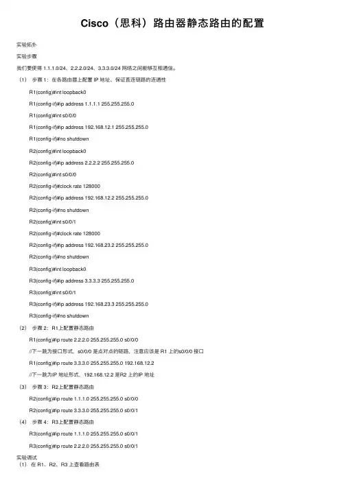
Cisco(思科)路由器静态路由的配置实验拓扑实验步骤我们要使得 1.1.1.0/24、2.2.2.0/24、3.3.3.0/24 ⽹络之间能够互相通信。
(1)步骤 1:在各路由器上配置 IP 地址、保证直连链路的连通性R1(config)#int loopback0R1(config-if)#ip address 1.1.1.1 255.255.255.0R1(config)#int s0/0/0R1(config-if)#ip address 192.168.12.1 255.255.255.0R1(config-if)#no shutdownR2(config)#int loopback0R2(config-if)#ip address 2.2.2.2 255.255.255.0R2(config)#int s0/0/0R2(config-if)#clock rate 128000R2(config-if)#ip address 192.168.12.2 255.255.255.0R2(config-if)#no shutdownR2(config)#int s0/0/1R2(config-if)#clock rate 128000R2(config-if)#ip address 192.168.23.2 255.255.255.0R2(config-if)#no shutdownR3(config)#int loopback0R3(config-if)#ip address 3.3.3.3 255.255.255.0R3(config)#int s0/0/1R3(config-if)#ip address 192.168.23.3 255.255.255.0R3(config-if)#no shutdown(2)步骤 2:R1上配置静态路由R1(config)#ip route 2.2.2.0 255.255.255.0 s0/0/0//下⼀跳为接⼝形式,s0/0/0 是点对点的链路,注意应该是 R1 上的s0/0/0 接⼝R1(config)#ip route 3.3.3.0 255.255.255.0 192.168.12.2//下⼀跳为IP 地址形式,192.168.12.2 是R2 上的IP 地址(3)步骤 3:R2上配置静态路由R2(config)#ip route 1.1.1.0 255.255.255.0 s0/0/0R2(config)#ip route 3.3.3.0 255.255.255.0 s0/0/1(4)步骤 4:R3上配置静态路由R3(config)#ip route 1.1.1.0 255.255.255.0 s0/0/1R3(config)#ip route 2.2.2.0 255.255.255.0 s0/0/1实验调试(1)在 R1、R2、R3 上查看路由表R1#show ip routeCodes: C - connected, S - static, R - RIP, M - mobile, B - BGPD - EIGRP, EX - EIGRP external, O - OSPF, IA - OSPF inter areaN1 - OSPF NSSA external type 1, N2 - OSPF NSSA external type 2E1 - OSPF external type 1, E2 - OSPF external type 2 i - IS-IS, su - IS-IS summary, L1 - IS-IS level-1, L2 - IS-IS level-2 ia - IS-IS inter area, * - candidate default, U - per-user static routeo - ODR, P - periodic downloaded static routeGateway of last resort is not setC 192.168.12.0/24 is directly connected, Serial0/0/01.0.0.0/24 is subnetted, 1 subnetsC 1.1.1.0 is directly connected, Loopback02.0.0.0/24 is subnetted, 1 subnetsS 2.2.2.0 is directly connected, Serial0/0/03.0.0.0/24 is subnetted, 1 subnetsS 3.3.3.0 [1/0] via 192.168.12.2R2#show ip routeCodes: C - connected, S - static, R - RIP, M - mobile, B - BGPD - EIGRP, EX - EIGRP external, O - OSPF, IA - OSPF inter areaN1 - OSPF NSSA external type 1, N2 - OSPF NSSA external type 2E1 - OSPF external type 1, E2 - OSPF external type 2i - IS-IS, su - IS-IS summary, L1 - IS-IS level-1, L2 - IS-IS level-2ia - IS-IS inter area, * - candidate default, U - per-user static routeo - ODR, P - periodic downloaded static routeGateway of last resort is not setC 192.168.12.0/24 is directly connected, Serial0/0/01.0.0.0/24 is subnetted, 1 subnetsS 1.1.1.0 is directly connected, Serial0/0/02.0.0.0/24 is subnetted, 1 subnetsC 2.2.2.0 is directly connected, Loopback03.0.0.0/24 is subnetted, 1 subnetsS 3.3.3.0 is directly connected, Serial0/0/1C 192.168.23.0/24 is directly connected, Serial0/0/1R3#show ip routeCodes: C - connected, S - static, R - RIP, M - mobile, B - BGPD - EIGRP, EX - EIGRP external, O - OSPF, IA - OSPF inter areaN1 - OSPF NSSA external type 1, N2 - OSPF NSSA external type 2E1 - OSPF external type 1, E2 - OSPF external type 2i - IS-IS, su - IS-IS summary, L1 - IS-IS level-1, L2 - IS-IS level-2ia - IS-IS inter area, * - candidate default, U - per-user static routeo - ODR, P - periodic downloaded static routeGateway of last resort is not set1.0.0.0/24 is subnetted, 1 subnetsS 1.1.1.0 is directly connected, Serial0/0/12.0.0.0/24 is subnetted, 1 subnetsS 2.2.2.0 is directly connected, Serial0/0/13.0.0.0/24 is subnetted, 1 subnets C 3.3.3.0 is directly connected, Loopback0C 192.168.23.0/24 is directly connected, Serial0/0/1(2)从各路由器的环回⼝ ping 其他路由器的环回⼝:R1#ping//不带任何参数的 ping命令,允许我们输⼊更多的参数Protocol [ip]:Target IP address: 2.2.2.2 //⽬标IP地址Repeat count [5]: //发送的ping 次数Datagram size [100]: //ping包的⼤⼩Timeout in seconds [2]: //超时时间Extended commands [n]: y //是否进⼀步扩展命令Source address or interface: 1.1.1.1 //源IP地址Type of service [0]:Set DF bit in IP header? [no]:Validate reply data? [no]:Data pattern [0xABCD]:Loose, Strict, Record, Timestamp, Verbose[none]:Sweep range of sizes [n]:Type escape sequence to abort.Sending 5, 100-byte ICMP Echos to 2.2.2.2, timeout is 2 seconds:Packet sent with a source address of 1.1.1.1Success rate is 100 percent (5/5), round-trip min/avg/max = 12/14/16 ms//以上说明从 R1 的 loopback0 可以ping 通R2 上的 loopback0。
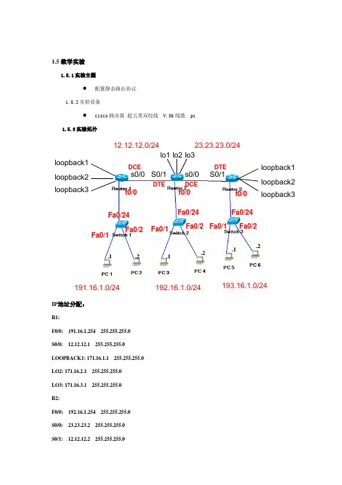
1.5教学实验 1.5.1实验主题●配置静态路由协议1.5.2实验设备●cisco 路由器 超五类双绞线 V.35线缆 pc1.5.3实验拓扑IP 地址分配:R1:F0/0: 191.16.1.254 255.255.255.0 S0/0: 12.12.12.1 255.255.255.0 LOOPBACK1: 171.16.1.1 255.255.255.0 LO2: 171.16.2.1 255.255.255.0 LO3: 171.16.3.1 255.255.255.0 R2:F0/0: 192.16.1.254 255.255.255.0 S0/0: 23.23.23.2 255.255.255.0 S0/1: 12.12.12.2 255.255.255.0s0/0 s0/0 S0/1S0/1 loopback1 lo1 lo2 lo3loopback2 loopback3loopback1 loopback2loopback3DCEDCEDTEDTE12.12.12.0/24 23.23.23.0/24191.16.1.0/24192.16.1.0/24193.16.1.0/24f0/0 f0/0 f0/0 Fa0/24Fa0/24Fa0/24 Fa0/1Fa0/1Fa0/1Fa0/2 Fa0/2 Fa0/2.1.2.1.1.2.2LO1: 172.16.1.1 255.255.255.0LO2: 172.16.2.1 255.255.255.0LO3: 172.16.3.1 255.255.255.0R3:F0/0: 193.16.1.254 255.255.255.0S0/1: 23.23.23.3 255.255.255.0LO1: 173.16.1.1 255.255.255.0LO2: 173.16.2.1 255.255.255.0LO3: 173.16.3.1 255.255.255.0PC1:191.16.1.1 255.255.255.0PC2:191.16.1.2 255.255.255.0PC3:192.16.1.1 255.255.255.0PC4:192.16.1.2 255.255.255.0PC5:193.16.1.1 255.255.255.0PC6:193.16.1.2 255.255.255.0Sw1: 191.16.1.253 255.255.255.0Sw2: 192.16.1.253 255.255.255.0Sw3: 193.16.1.253 255.255.255.01.5.4实验要求●通过静态路由的配置使不同网段能够相互通信。
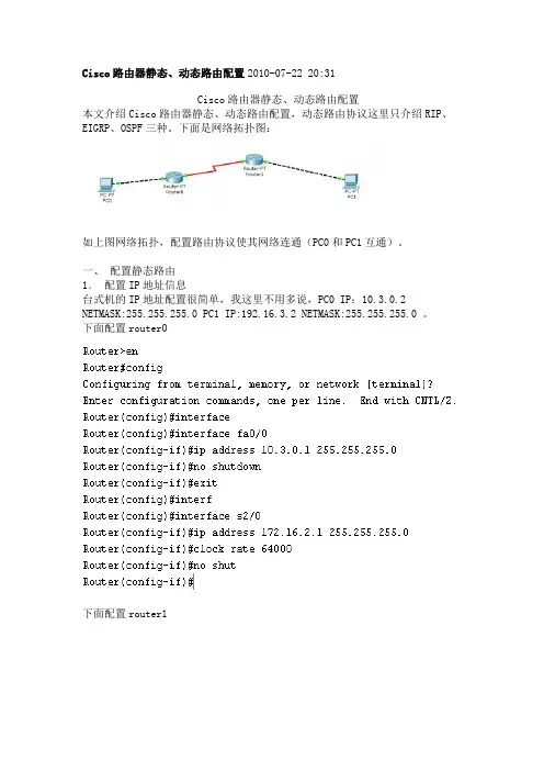
Cisco路由器静态、动态路由配置2010-07-22 20:31Cisco路由器静态、动态路由配置本文介绍Cisco路由器静态、动态路由配置,动态路由协议这里只介绍RIP、EIGRP、OSPF三种。
下面是网络拓扑图:如上图网络拓扑,配置路由协议使其网络连通(PC0和PC1互通)。
一、配置静态路由1.配置IP地址信息台式机的IP地址配置很简单,我这里不用多说,PC0 IP:10.3.0.2 NETMASK:255.255.255.0 PC1 IP:192.16.3.2 NETMASK:255.255.255.0 。
下面配置router0下面配置router1这里我们来试试PC0和PC1互通性PC0 ping PC1如图所示:这里我们看到PC0和PC1并不能相通。
PC1 ping PC0如图所示:这里我们看到PC1和PC0也并不能相通。
2.配置静态路由协议Router(config)#ip route 192.16.3.0 255.255.255.0 172.16.2.2 R1(config)#ip route 10.3.0.0 255.255.255.0 172.16.2.1 下面我们再来试试PC0和PC1互通性PC0 ping PC1如图所示:这里我们看到PC0和PC1能相通,我们配置的静态路由协议起作用了。
PC1 ping PC0如图所示:这里我们看到PC1和PC0能相通,我们配置的静态路由协议也起作用了。
二、 RIP路由协议的配置1. 配置IP地址信息配置IP地址信息见上面配置静态路由中配置IP地址信息,我这里不多说。
这里配置了ip地址以后如静态路由中一样,PC0和PC1不能相通。
2. 配置rip路由协议配置router0Router(config)#router ripRouter(config-router)#version 2Router(config-router)#network 10.3.0.0Router(config-router)#network 172.16.2.0配置router1R1(config)#router ripR1(config-router)#version 2R1(config-router)#network 192.16.3.0R1(config-router)#network 172.16.2.03. 查看rip路由信息查看router0查看router1这里我们可以看到R开头的路由信息即是通过rip协议得到的路由信息。
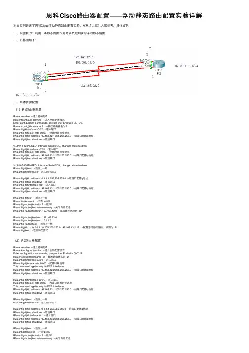
思科Cisco路由器配置——浮动静态路由配置实验详解本⽂实例讲述了思科Cisco浮动静态路由配置实验。
分享给⼤家供⼤家参考,具体如下:⼀、实验⽬的:利⽤⼀条静态路由作为两条负载均衡的浮动静态路由⼆、拓扑图如下:三、具体步骤配置(1)R1路由器配置Router>enable --进⼊特权模式Router#configure terminal --进⼊全局配置模式Enter configuration commands, one per line. End with CNTL/Z.Router(config)#hostname R1 --修改路由器名为R1R1(config)#interface s0/0/0 --进⼊端⼝R1(config-if)#clock rate 64000 --设置时钟同步速率R1(config-if)#ip address 192.168.12.1 255.255.255.0 --给端⼝配置ip地址R1(config-if)#no shutdown --激活端⼝%LINK-5-CHANGED: Interface Serial0/0/0, changed state to downR1(config-if)#interface s0/0/1 --进⼊端⼝R1(config-if)#clock rate 64000 --设置时钟同步速率R1(config-if)#ip address 192.168.23.2 255.255.255.0 --给端⼝配置ip地址R1(config-if)#no shutdown --激活端⼝%LINK-5-CHANGED: Interface Serial0/0/1, changed state to downR1(config-if)#exit --返回上⼀级R1(config)#interface l0 --进⼊回环端⼝R1(config-if)#ip address 10.1.1.1 255.255.255.0 --给端⼝配置ip地址R1(config-if)#no shutdown --激活端⼝R1(config-if)#interface f0/0 --进⼊端⼝R1(config-if)#ip address 192.168.13.1 255.255.255.0 --给端⼝配置ip地址R1(config-if)#no shutdown --激活端⼝R1(config-if)#exit --返回上⼀级R1(config)#route rip --开启rip协议R1(config-router)#version 2 --版本2R1(config-router)#no auto-summary --关闭⾃动汇总R1(config-router)#network 192.168.12.0 --添加直连⽹段到RIPR1(config-router)#network 192.168.23.0R1(config-router)#network 10.1.1.0R1(config-router)#exit --返回上⼀级R1(config)#ip route 20.1.1.0 255.255.255.0 192.168.13.2 121 --配置浮动静态路由,级别为121R1(config)#end --返回特权模式(2)R2路由器配置Router>enable --进⼊特权模式Router#configure terminal --进⼊全局配置模式Enter configuration commands, one per line. End with CNTL/Z.Router(config)#hostname R2 --修改路由器名为R2R2(config)#interface s0/0/1 --进⼊端⼝R2(config-if)#clock rate 64000 --配置时钟速率This command applies only to DCE interfacesR2(config-if)#ip address 192.168.12.2 255.255.255.0 --给端⼝配置ip地址R2(config-if)#no shutdown --激活端⼝R2(config-if)#interface s0/0/0 --进⼊端⼝R2(config-if)#clock rate 64000 --为端⼝配置时钟速率This command applies only to DCE interfacesR2(config-if)#ip address 192.168.23.1 255.255.255.0 --给端⼝配置ip地址R2(config-if)#no shutdown --激活端⼝R2(config-if)#exit --返回上⼀级R2(config)#interface l0 --进⼊回环端⼝R2(config-if)#ip address 20.1.1.1 255.255.255.0 --给端⼝配置ip地址R2(config-if)#no shutdown --激活端⼝R2(config-if)#interface f0/1 --进⼊端⼝R2(config-if)#ip address 192.168.13.2 255.255.255.0 --给端⼝配置ip地址R2(config-if)#no shutdown --激活端⼝R2(config-if)#exit --返回上⼀级R2(config)#route rip --开启rip协议R2(config-router)#version 2 --版本2R2(config-router)#no auto-summary --关闭⾃动汇总R2(config-router)#network 192.168.12.0 --添加直连⽹段到RIPR2(config-router)#network 192.168.23.0R2(config-router)#network 20.1.1.0R2(config-router)#exit --返回上⼀级R2(config)#ip route 10.1.1.0 255.255.255.0 192.168.13.1 121 --配置浮动静态路由,级别为121 R2(config)#end --返回特权模式四、验证1、分别查看R1与R2路由表信息(1)R1路由表信息(2)R2路由表信息2、断开两条负载均衡路径(12.0与23.0⽹段)并查看路由表信息(1)R1路由表信息(2)R2路由表信息解释:当两条负载均衡路径断掉,这条浮动的静态路由就会出现。
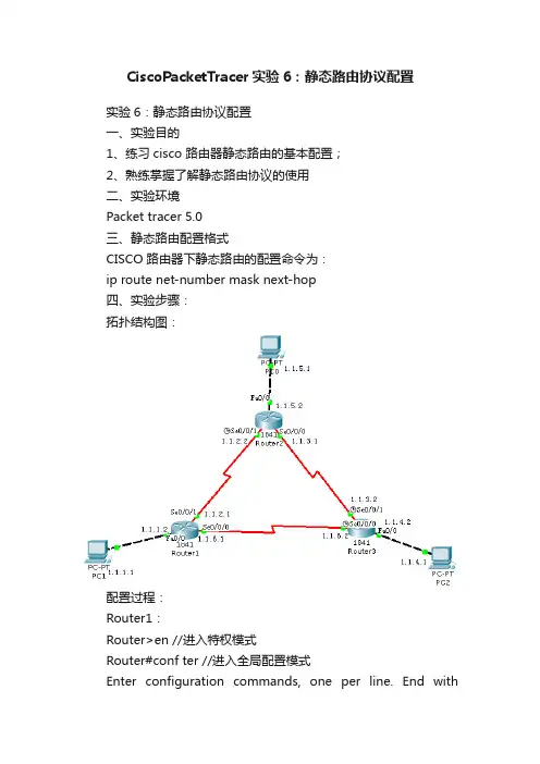
CiscoPacketTracer实验6:静态路由协议配置实验6:静态路由协议配置一、实验目的1、练习cisco 路由器静态路由的基本配置;2、熟练掌握了解静态路由协议的使用二、实验环境Packet tracer 5.0三、静态路由配置格式CISCO 路由器下静态路由的配置命令为:ip route net-number mask next-hop四、实验步骤:拓扑结构图:配置过程:Router1:Router>en //进入特权模式Router#conf ter //进入全局配置模式Enter configuration commands, one per line. End withCNTL/Z. Router(config)#int f0/0 //配置Fa0/0 接口Router(config-if)#ip add 1.1.1.2 255.255.255.0Router(config-if)#no shu%LINK-5-CHANGED: Interface FastEthernet0/0, changed state to up%LINEPROTO-5-UPDOWN: Line protocol on Interface FastEthernet0/0, changed state to upRouter(config-if)#exiRouter(config)#int serial 0/0/1 //配置串口Router(config-if)#ip add 1.1.2.1 255.255.255.0Router(config-if)#clock rate 64000Router(config-if)#no shutdown%LINK-5-CHANGED: Interface Serial0/0/1, changed state to downRouter(config-if)#exiRouter(config)#int s0/0/0 //配置串口Router(config-if)#ip add 1.1.6.1 255.255.255.0Router(config-if)#clock rate 64000Router(config-if)#no shutdown%LINK-5-CHANGED: Interface Serial0/0/0, changed state to downRouter(config)#ip route 1.1.4.0 255.255.255.0 1.1.6.2 //静态路由Router(config)#ip route 1.1.5.0 255.255.255.0 1.1.2.2 //静态路由Router(config)#Router2:Router>en //进入特权模式Router#conf ter //进入全局配置模式Enter configuration commands, one per line. End withCNTL/Z.Router(config)#interface f0/0 //配置Fa0/0 接口Router(config-if)#ip add 1.1.5.2 255.255.255.0Router(config-if)#no shutdownRouter(config-if)#exitRouter(config)#interface s0/0/0 //配置串口Router(config-if)#ip add 1.1.3.1 255.255.255.0Router(config-if)#clock rate 64000Router(config-if)#no shutdownRouter(config-if)#exitRouter(config)#interface s0/0/1 //配置串口Router(config-if)#ip add 1.1.2.2 255.255.255.0Router(config-if)#clock rate 64000Router(config-if)#no shutdownRouter(config-if)#exitRouter(config)#ip route 1.1.1.0 255.255.255.0 1.1.2.1 //静态路由Router(config)#ip route 1.1.4.0 255.255.255.0 1.1.3.2 //静态路由Router(config)#Router3:Router>en //进入特权模式Router#conf ter //进入全局配置模式Enter configuration commands, one per line. End with CNTL/Z.Router(config)#int f0/0 //配置Fa0/0 接口Router(config-if)#ip add 1.1.4.2 255.255.255.0Router(config-if)#no shutdown%LINK-5-CHANGED: Interface FastEthernet0/0, changed state to up%LINEPROTO-5-UPDOWN: Line protocol on Interface FastEthernet0/0, changed state to upRouter(config-if)#exiRouter(config)#int s0/0/1 //配置串口Router(config-if)#ip add 1.1.3.2 255.255.255.0Router(config-if)#clock rate 64000Router(config-if)#no shutdown%LINK-5-CHANGED: Interface Serial0/0/1, changed state to upRouter(config-if)#exitRouter(config)#int s0/0/0 //配置串口Router(config-if)#ip add 1.1.6.2 255.255.255.0Router(config-if)#clock rate 64000Router(config-if)#no shutdown%LINK-5-CHANGED: Interface Serial0/0/0, changed state to upRouter(config)#ip route 1.1.5.0 255.255.255.0 1.1.3.1 //静态路由Router(config)#ip route 1.1.1.0 255.255.255.0 1.1.6.1 //静态路由Router(config)#之后按照图示配置好主机的IP 地址,使用ping 命令测试相互之间的连通性,主机之间可以相互ping 通的。
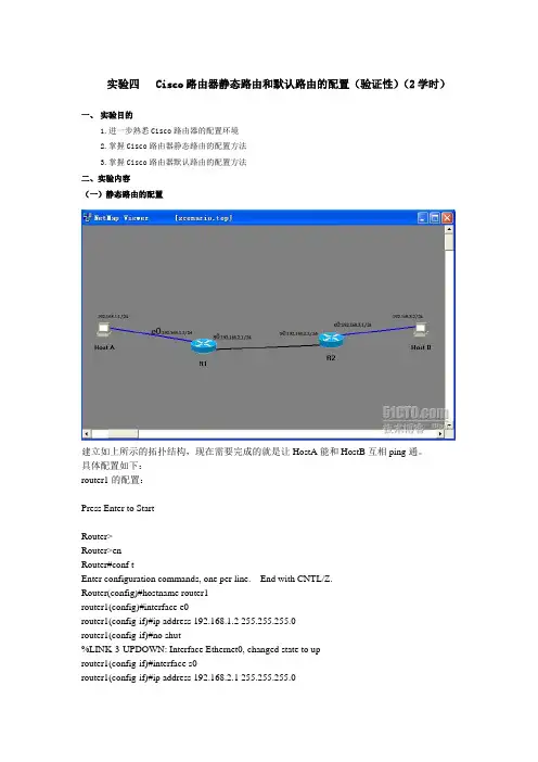
实验四 Cisco路由器静态路由和默认路由的配置(验证性)(2学时)一、实验目的1.进一步熟悉Cisco路由器的配置环境2.掌握Cisco路由器静态路由的配置方法3.掌握Cisco路由器默认路由的配置方法二、实验内容(一)静态路由的配置建立如上所示的拓扑结构,现在需要完成的就是让HostA能和HostB互相ping通。
具体配置如下:router1的配置:Press Enter to StartRouter>Router>enRouter#conf tEnter configuration commands, one per line. End with CNTL/Z.Router(config)#hostname router1router1(config)#interface e0router1(config-if)#ip address 192.168.1.2 255.255.255.0router1(config-if)#no shut%LINK-3-UPDOWN: Interface Ethernet0, changed state to uprouter1(config-if)#interface s0router1(config-if)#ip address 192.168.2.1 255.255.255.0router1(config-if)#clock rate 6400 //clock rate是dce设备给dte设备提供时钟频率的,需要在dce里面设置,而另外的一个路由器里面则不用设置router1(config-if)#no shut%LINK-3-UPDOWN: Interface Serial0, changed state to uprouter1(config-if)#end%LINK-3-UPDOWN: Interface Serial0, changed state to down%LINEPROTO-5-UPDOWN: Line protocol on Interface Serial0, changed state to downrouter1#config tEnter configuration commands, one per line. End with CNTL/Z.router1(config)#ip route 192.168.3.0 255.255.255.0 192.168.2.1 //设定静态路由router1(config)#ip route 192.168.2.0 255.255.255.0 192.168.2.1router1(config)#endrouter1#copy running startupDestination filename [startup-config]?Building configuration...[OK]%LINK-3-UPDOWN: Interface Serial0, changed state to up%LINEPROTO-5-UPDOWN: Line protocol on Interface Serial0, changed state to uprouter2的配置:Press Enter to StartRouter>enRouter#conf tEnter configuration commands, one per line. End with CNTL/Z.Router(config)#interface e0Router(config-if)#endRouter#config tEnter configuration commands, one per line. End with CNTL/Z.Router(config)#hostname router2router2(config)#interface s0router2(config-if)#ip address 192.168.2.2 255.255.255.0router2(config-if)#no shut%LINK-3-UPDOWN: Interface Serial0, changed state to uprouter2(config-if)#interface s0router2(config-if)#interface e0router2(config-if)#ip address 192.168.3.1 255.255.255.0router2(config-if)#no shut%LINK-3-UPDOWN: Interface Ethernet0, changed state to uprouter2(config-if)#endrouter2#config tEnter configuration commands, one per line. End with CNTL/Z.router2(config)#ip route 192.168.1.0 255.255.255.0 192.168.2.2router2(config)#ip route 192.168.2.0 255.255.255.0 192.168.2.2router2(config)#endrouter2#copy running startupDestination filename [startup-config]?Building configuration...[OK]router2#ping 192.168.1.2Type escape sequence to abort.Sending 5, 100-byte ICMP Echos to 192.168.1.2, timeout is 2 seconds:!!!!!Success rate is 100 percent (5/5), round-trip min/avg/max = 1/2/4 msrouter2#ping 192.168.2.1Type escape sequence to abort.Sending 5, 100-byte ICMP Echos to 192.168.2.1, timeout is 2 seconds:!!!!!Success rate is 100 percent (5/5), round-trip min/avg/max = 1/2/4 msrouter2#ping 192.168.2.2Type escape sequence to abort.Sending 5, 100-byte ICMP Echos to 192.168.2.2, timeout is 2 seconds:!!!!!Success rate is 100 percent (5/5), round-trip min/avg/max = 1/2/4 ms //路由器之间试ping 一下,应该可以ping通,接下来配pcpc1的配置如下:Boson BOSS 5.0Copyright 1998-2003 Boson Software, Inc.Use the command help to get startedPress Enter to beginC:>ipconfig /ip 192.168.1.1 255.255.255.0 //此时尚未指定网关C:>ping 192.168.2.1Pinging 192.168.2.1 with 32 bytes of data:Request timed out.Request timed out.Request timed out.Request timed out.Request timed out.Ping statistics for 192.168.2.1:Packets: Sent = 5, Received = 0, Lost = 5 (100% loss), //未指定网关时不能ping通router1的s0Approximate round trip times in milli-seconds:Minimum = 0ms, Maximum = 0ms, Average = 0msC:>ipconfig /dg 192.168.1.2 //指定网关为与本机直连的router1的e0口C:>ping 192.168.1.2Pinging 192.168.1.2 with 32 bytes of data:Reply from 192.168.1.2: bytes=32 time=60ms TTL=241Reply from 192.168.1.2: bytes=32 time=60ms TTL=241Reply from 192.168.1.2: bytes=32 time=60ms TTL=241Reply from 192.168.1.2: bytes=32 time=60ms TTL=241Reply from 192.168.1.2: bytes=32 time=60ms TTL=241Ping statistics for 192.168.1.2: Packets: Sent = 5, Received = 5, Lost = 0 (0% loss), Approximate round trip times in milli-seconds:Minimum = 50ms, Maximum = 60ms, Average = 55msC:>ping 192.168.2.1Pinging 192.168.2.1 with 32 bytes of data:Reply from 192.168.2.1: bytes=32 time=60ms TTL=241Reply from 192.168.2.1: bytes=32 time=60ms TTL=241Reply from 192.168.2.1: bytes=32 time=60ms TTL=241Reply from 192.168.2.1: bytes=32 time=60ms TTL=241Reply from 192.168.2.1: bytes=32 time=60ms TTL=241Ping statistics for 192.168.2.1: Packets: Sent = 5, Received = 5, Lost = 0 (0% loss), //指定网关后可以ping通s0口了Approximate round trip times in milli-seconds:Minimum = 50ms, Maximum = 60ms, Average = 55msC:>ping 192.168.2.2Pinging 192.168.2.2 with 32 bytes of data:Reply from 192.168.2.2: bytes=32 time=60ms TTL=241Reply from 192.168.2.2: bytes=32 time=60ms TTL=241Reply from 192.168.2.2: bytes=32 time=60ms TTL=241Reply from 192.168.2.2: bytes=32 time=60ms TTL=241Reply from 192.168.2.2: bytes=32 time=60ms TTL=241Ping statistics for 192.168.2.2: Packets: Sent = 5, Received = 5, Lost = 0 (0% loss), Approximate round trip times in milli-seconds:Minimum = 50ms, Maximum = 60ms, Average = 55msC:>ping 192.168.3.1Pinging 192.168.3.1 with 32 bytes of data:Reply from 192.168.3.1: bytes=32 time=60ms TTL=241Reply from 192.168.3.1: bytes=32 time=60ms TTL=241Reply from 192.168.3.1: bytes=32 time=60ms TTL=241Reply from 192.168.3.1: bytes=32 time=60ms TTL=241Reply from 192.168.3.1: bytes=32 time=60ms TTL=241Ping statistics for 192.168.3.1: Packets: Sent = 5, Received = 5, Lost = 0 (0% loss), Approximate round trip times in milli-seconds:Minimum = 50ms, Maximum = 60ms, Average = 55ms//可以ping通任意一台设备的IP地址,实验成功C:>pc2 的配置如下:Boson BOSS 5.0Copyright 1998-2003 Boson Software, Inc.Use the command help to get startedPress Enter to beginC:>C:>ipconfig /ip 192.168.3.1 255.255.255.0C:>ipconfig /dg 192.168.3.1 //把IP和网关设好C:>ping 192.168.1.1Pinging 192.168.1.1 with 32 bytes of data:Reply from 192.168.1.1: bytes=32 time=60ms TTL=241Reply from 192.168.1.1: bytes=32 time=60ms TTL=241Reply from 192.168.1.1: bytes=32 time=60ms TTL=241Reply from 192.168.1.1: bytes=32 time=60ms TTL=241Reply from 192.168.1.1: bytes=32 time=60ms TTL=241Ping statistics for 192.168.1.1: Packets: Sent = 5, Received = 5, Lost = 0 (0% loss), Approximate round trip times in milli-seconds:Minimum = 50ms, Maximum = 60ms, Average = 55msC:>ping 192.168.1.2Pinging 192.168.1.2 with 32 bytes of data:Reply from 192.168.1.2: bytes=32 time=60ms TTL=241Reply from 192.168.1.2: bytes=32 time=60ms TTL=241Reply from 192.168.1.2: bytes=32 time=60ms TTL=241Reply from 192.168.1.2: bytes=32 time=60ms TTL=241Reply from 192.168.1.2: bytes=32 time=60ms TTL=241Ping statistics for 192.168.1.2: Packets: Sent = 5, Received = 5, Lost = 0 (0% loss), Approximate round trip times in milli-seconds:Minimum = 50ms, Maximum = 60ms, Average = 55msC:>ping 192.168.2.1Pinging 192.168.2.1 with 32 bytes of data:Reply from 192.168.2.1: bytes=32 time=60ms TTL=241Reply from 192.168.2.1: bytes=32 time=60ms TTL=241Reply from 192.168.2.1: bytes=32 time=60ms TTL=241Reply from 192.168.2.1: bytes=32 time=60ms TTL=241Reply from 192.168.2.1: bytes=32 time=60ms TTL=241Ping statistics for 192.168.2.1: Packets: Sent = 5, Received = 5, Lost = 0 (0% loss), Approximate round trip times in milli-seconds:Minimum = 50ms, Maximum = 60ms, Average = 55msC:>ping 192.168.2.2Pinging 192.168.2.2 with 32 bytes of data:Reply from 192.168.2.2: bytes=32 time=60ms TTL=241Reply from 192.168.2.2: bytes=32 time=60ms TTL=241Reply from 192.168.2.2: bytes=32 time=60ms TTL=241Reply from 192.168.2.2: bytes=32 time=60ms TTL=241Reply from 192.168.2.2: bytes=32 time=60ms TTL=241Ping statistics for 192.168.2.2: Packets: Sent = 5, Received = 5, Lost = 0 (0% loss), Approximate round trip times in milli-seconds:Minimum = 50ms, Maximum = 60ms, Average = 55msC:>ping 192.168.3.1Pinging 192.168.3.1 with 32 bytes of data:Reply from 192.168.3.1: bytes=32 time=60ms TTL=241Reply from 192.168.3.1: bytes=32 time=60ms TTL=241Reply from 192.168.3.1: bytes=32 time=60ms TTL=241Reply from 192.168.3.1: bytes=32 time=60ms TTL=241Reply from 192.168.3.1: bytes=32 time=60ms TTL=241Ping statistics for 192.168.3.1: Packets: Sent = 5, Received = 5, Lost = 0 (0% loss), Approximate round trip times in milli-seconds:Minimum = 50ms, Maximum = 60ms, Average = 55ms //可以ping通任意一台设备的IP地址,实验成功(二)默认路由的配置建立如上所示的拓扑结构。
cisco设置方法步骤思科(Cisco)路由器是一个集成多业务路由器,福利综合服务网络路由器,以及获得回报的网络路由器。
cisco路由器怎么设置??有网友提到自己不会设置思科的设备,该怎么办?店铺在网上找了一些教程及命令,需要的朋友可以参考下。
以下是cisco路由器设置具体命令一、 host到router1、实验网络拓扑:pc( client 4.01)---switch---router1720 ( access server)pc配置:ip:10.130.23.242/28gw:10.130.23.2461720接口ip:f0:10.130.23.246/28lo0:172.16.1.1/241720的ios为c1700-k93sy7-mz.122-8.T5.bin2、步骤:1、配置isakmp policy:crypto isakmp policy 1encr 3desauthen pre-sharegroup 22、配置 client地址池cry isa client conf address-pool local pool192ip local pool pool192 192.168.1.1 192.168.1.2543、配置 client有关参数cry isa client conf group vclient-group####vclient-group就是在client的连接配置中需要输入的group authentication name。
key vclient-key####vclient-key就是在client的连接配置中需要输入的group authentication password。
pool pool192 ####client的ip地址从这里选取####以上两个参数必须配置,其他参数还包括domain、dns、wins等,根据情况进行配置。
4、配置ipsec transform-setcry ipsec trans vclient-tfs esp-3des esp-sha-hmac5、配置map模板cry dynamic-map template-map 1set transform-set vclient-tfs ####和第四步对应6、配置mapcry map map 1 ipsec-isakmp dynamic template-map#### 使用第?*脚渲玫?map 模板cry map map isakmp author list vclient-group ####使用第三步配置的参数authorizationcry map map client conf address respond ####响应client分配地址的请求7、配置静态路由ip route 192.168.1.0 255.255.255.0 fastethernet03、说明几点:(1)因为1720只有一个fastethernet口,所以用router1720上的lo0地址来模拟router内部网络。

路由原理与静态路由在互连网上,每时每刻有数以万计的路由器为数据的转发而忙碌。
路由器转发数包,必须依靠一张表-----路由表。
路由:指导路由器进行数据转发的路径信息。
路由器根据路由表,选择最佳路径,将数据包转发到目标网段。
路由器收到数据包后,会根据目的IP选择一条最优的路径,将数据包转到下一跳路由器,路径上最后的路由器负责将数据包送交目的主机。
(类似于体育运动中的接力赛一样,每一个路由器负责将数据包按照最优的路径向下一跳路由器进行转发,通过多个路由器一站一站的接力,最终将数据包转到目的地。
)路由表的主要参数:( 以R1为例)目标网段下一跳出接口度量值201.1.1.0 / 24 R2S1/0 3202.1.1.0 / 24 R2S1/0 3路由表中包含了可以到达的目的网络,目的网络在路由表中不存在的数据包会被丢弃。
为了保障数据的正常通信,要求网络中所有的路由器都有正确的、完整的路由表。
数据通信是双向的,所有路由器要有前往目标的路由,同时还要有返回数据源的路由。
数据转发1.同一网段:直接封装对方的MAC地址,直接发送。
(不需要R)2.不同网段:封装网关的MAC地址,由网关路由器进行转发。
(需要R)说明:对于PC来说,当与不同网段通信时,必须要设置默认网关。
默认网关就是自己直连的路由器的以太口。
路由表的建立根据来源的不同,路由表的路由通常可分为以下三类:直连路由:链路层协议发现的路由(接口双UP,正确配置IP地址)静态路由:手工设置动态路由:动态学习,依靠各种路由协议,如RIP、OSPF、BGP等。
一、静态路由人工静态设置的路由信息。
分析:在路由器R1上,只要为F0/0和S1/0 配置IP地址,并且激活接口,路由器R1便可以自动建立直连的路由条目。
对于3.0网段R1是不能直接感觉到的,所以需要人工去告诉它。
可以告诉路由器R1:3.0网段在它的S1/0口方向,下一跳是192.168.2.2.格式:R1(config)# ip route 目标网段子网掩码下一跳命令配置:R1(config)#ip route 192.168.3.0 255.255.255.0 192.168.2.2r1#sh ip route // 查看路由表说明:静态路由的优缺点优点:静态存在,稳定,不占用网络带宽和路由器CPU资源。

CISCO路由器配置手册第一章路由器配置基础一、二、三、四、五、六、第二章广域网协议设置一、二、三、四、五、六、第三章路由协议设置一、二、三、四、五、第四章服务质量及访问控制一、二、三、第五章虚拟局域网(VLAN)路由一、二、三、第一章路由器配置基础一、基本设置方式一般来说,可以用5种方式来设置路由器:1.Console口接终端或运行终端仿真软件的微机;2.AUX口接MODEM,通过电话线与远方的终端或运行终端仿真软件的微机相连;3.通过Ethernet上的TFTP服务器;4.通过Ethernet上的TELNET程序;5.通过Ethernet上的SNMP网管工作站。
但路由器的第一次设置必须通过第一种方式进行,此时终端的硬件设置如下:波特率:9600数据位:8停止位:1奇偶校验: 无二、命令状态1. router>路由器处于用户命令状态,这时用户可以看路由器的连接状态,访问其它网络和主机,但不能看到和更改路由器的设置内容。
2. router#在router>提示符下键入enable,路由器进入特权命令状态router#,这时不但可以执行所有的用户命令,还可以看到和更改路由器的设置内容。
3. router(config)#在router#提示符下键入configure terminal,出现提示符router(config)#,此时路由器处于全局设置状态,这时可以设置路由器的全局参数。
4. router(config-if)#; router(config-line)#; router(config-router)#;… 路由器处于局部设置状态,这时可以设置路由器某个局部的参数。
5. >路由器处于RXBOOT状态,在开机后60秒内按ctrl-break可进入此状态,这时路由器不能完成正常的功能,只能进行软件升级和手工引导。
6. 设置对话状态这是一台新路由器开机时自动进入的状态,在特权命令状态使用SETUP命令也可进入此状态,这时可通过对话方式对路由器进行设置。
cisco静态路由的应用怎么配置思科cisco生产的路由器、交换机设备和其他设备承载了全世界80%的互联网通信,成为硅谷中新经济的传奇,那么你知道cisco静态路由的应用怎么配置吗?下面是店铺整理的一些关于cisco静态路由的应用怎么配置的相关资料,供你参考。
cisco静态路由的应用配置的方法:静态路由的应用Switch 0 的配置:Switch>enSwitch>enableSwitch#confSwitch#configureSwitch#configure terminalEnter configuration commands, one per line. End with CNTL/Z.Switch(config)#intSwitch(config)#interface f0/1Switch(config-if)#no swiSwitch(config-if)#no switchport%LINEPROTO-5-UPDOWN: Line protocol on Interface FastEthernet0/1, changed state to down%LINEPROTO-5-UPDOWN: Line protocol on Interface FastEthernet0/1, changed state to upSwitch(config-if)# Switch(config-if)#ip addSwitch(config-if)#ip address 1.1.1.1 255.0.0.0Switch(config-if)#no shutSwitch(config-if)#no shutdownSwitch(config-if)#exitSwitch(config)#intSwitch(config)#interface fSwitch(config)#interface fastEthernet 0/2Switch(config-if)#ip addSwitch(config-if)#no swSwitch(config-if)#no switchport%LINEPROTO-5-UPDOWN: Line protocol on Interface FastEthernet0/2, changed state to down%LINEPROTO-5-UPDOWN: Line protocol on Interface FastEthernet0/2, changed state to upSwitch(config-if)# Switch(config-if)#ip addreSwitch(config-if)#ip address 2.2.2.1 255.0.0.0Switch(config-if)#no shutSwitch(config-if)#no shutdownSwitch(config-if)#exitSwitch(config)#ip route 4.0.0.0 255.0.0.0 fSwitch(config)#ip route 4.0.0.0 255.0.0.0 f?FastEthernetSwitch(config)#ip route 4.0.0.0 255.0.0.0 faSwitch(config)#ip route 4.0.0.0 255.0.0.0 fastEthernet 0/2Switch(config)#no shutSwitch(config)#exit%SYS-5-CONFIG_I: Configured from console by consoleSwitch#show ip routeCodes: C - connected, S - static, I - IGRP, R - RIP, M - mobile, B - BGPD - EIGRP, EX - EIGRP external, O - OSPF, IA - OSPF inter areaN1 - OSPF NSSA external type 1, N2 - OSPF NSSA external type 2E1 - OSPF external type 1, E2 - OSPF external type 2, E - EGPi - IS-IS, L1 - IS-IS level-1, L2 - IS-IS level-2, ia - IS-IS inter area* - candidate default, U - per-user static route, o - ODRP - periodic downloaded static routeGateway of last resort is not setC 1.0.0.0/8 is directly connected, FastEthernet0/1C 2.0.0.0/8 is directly connected, FastEthernet0/2S 4.0.0.0/8 is directly connected, FastEthernet0/2Switch#Switch#show ?access-lists List access listsadjacency Adjacent nodesarp Arp tablecdp CDP informationclock Display the system clockcontrollers Interface controllers statuscrypto Encryption moduledebugging State of each debugging optiondhcp Dynamic Host Configuration Protocol statusetherchannel EtherChannel informationflash: display information about flash: file systemframe-relay Frame-Relay informationhistory Display the session command historyhosts IP domain-name, lookup style, nameservers, and host tableinterfaces Interface status and configurationip IP informationipv6 IPv6 informationmac-address-table MAC forwarding tableospf For OSPF debug onlyospfv3 For OSPFv3 debug onlyprocesses Active process statisticsprotocols Active network routing protocolsrunning-config Current operating configurationsessions Information about Telnet connectionsspanning-tree Spanning tree topologyssh Status of SSH server connectionsstartup-config Contents of startup configurationtcp Status of TCP connectionsterminal Display terminal configuration parametersusers Display information about terminal linesversion System hardware and software statusvlan VTP VLAN statusvtp Configure VLAN databaseSwitch#show ip ?access-lists List access listsarp IP ARP tablecef Cisco Express Forwardingdhcp Show items in the DHCP databaseeigrp IP-EIGRP show commandsinterface IP interface status and configurationnat IP NAT informationospf OSPF informationprotocols IP routing protocol process parameters and statisticsrip IP RIP show commandsroute IP routing tablessh Information on SSHSwitch#show ip intSwitch#show ip interface ?Ethernet IEEE 802.3FastEthernet FastEthernet IEEE 802.3GigabitEthernet GigabitEthernet IEEE 802.3z Loopback Loopback interfaceSerial SerialVlan Catalyst Vlansbrief Brief summary of IP status and configurationSwitch#show ip interface fSwitch#show ip interface fastEthernet 0/1 FastEthernet0/1 is up, line protocol is up Internet protocol processing disabledSwitch#show ip interface fastEthernet 0/2 FastEthernet0/2 is up, line protocol is up Internet protocol processing disabledSwitch#show ruSwitch#show running-configBuilding configuration...Current configurat!hostname Switch ion : 1168 bytes!version 12.2no service password-encryption!!!!!ip ssh version 1!port-channel load-balance src-mac!interface FastEthernet0/1 no switchportip address 1.1.1.1 255.0.0.0 duplex autospeed auto!interface FastEthernet0/2 no switchportip address 2.2.2.1 255.0.0.0 duplex autospeed auto!。
实验6 路由器组网及静态路由配置(Cisco Packet Tracer)(设计性实验)1.实验目的1.掌握IP数据报转发的基本原理;2.掌握静态路由表的配置方法;3.进一步学习模拟软件“Cisco Packet Tracer ”4.初步了解Cisco系列路由器的基本配置方法(在路由器用户命令状态、特权命令状态、全局设置状态、局部设置状态等的参数配置方法);5.根据实验要求,设计正确的解决方案。
2.实验设备与环境1. 仿真软件Cisco Packet Tracer,或Cisco路由器若干台;2. 台式计算机3. 实验准备1.路由器的配置方法一般来说,可以用5种方式来设置路由器,其中包括Console 口接终端或运行终端仿真软件的微机;AUX口接MODEM,通过电话线与远方的终端或运行终端仿真软件的微机相连;通过以太网上的TFTP服务器;通过以太网上的TELNET程序;通过以太网上的SNMP 网管工作站。
第一次设置必须通过上述第一种方式进行。
2.Cisco IOSCisco IOS即Cisco网间网操作系统软件,它满足了端到端网络连接要求,并提供了网络扩展性,模块化结构和移植性,以及多媒体,安全性,网络管理,拨号和Internet应用等许多内嵌功能内。
Cisco IOS技术共有15000种特性,可以提供Internet智能,它可将各种不同的硬件连接起来,构筑成有效、无缝的基础设施,从而大大促进网络的增长和新应用的部署。
3.学习有关Cisco路由器的参数配置方法a)命令状态1)普通用户命令状态router>路由器处于普通用户命令状态。
这时用户可以看到路由器的连接状态,访问其它网络和主机,但不能看到和更改路由器的设置内容。
2)超级用户命令状态router#在router>提示符下键入enable路由器进入超级用户命令状态router#,这时不但可以执行所有的用户命令,还可以看到和更改路由器的设置内容。
思科路由器静态路由配置实验案例详解本⽂实例讲述了思科路由器静态路由配置实验。
分享给⼤家供⼤家参考,具体如下:实验⼋ 路由器静态路由配置⼀、实验⽬标1. 掌握静态路由的配置⽅法和技巧;2. 掌握通过静态路由⽅式实现⽹络的连通性;3. 熟悉⼴域⽹线缆的链接⽅式;⼆、实验背景 学校有新旧两个校区,每个校区是⼀个独⽴的局域⽹,为了使新旧校区能够正常相互通讯,共享资源。
每个校区出⼝利⽤⼀台路由器进⾏连接,两台路由器间学校申请了⼀条2M的DDN专线进⾏相连,要求做适当配置实现两个校区的正常相互访问。
三、技术原理1. 路由器属于⽹络层设备,能够根据IP包头的信息,选择⼀条最佳路径,将数据包转发出去。
实现不同⽹段的主机之间的互相访问。
路由器是根据路由表进⾏选路和转发的。
⽽路由表⾥就是由⼀条条路由信息组成。
2. ⽣成路由表主要有两种⽅法:⼿⼯配置和动态配置,即静态路由协议配置和动态路由协议配置。
3. 静态路由是指有⽹络管理员⼿⼯配置的路由信息。
4. 静态路由除了具有简单、⾼效、可靠的优点外,它的另⼀个好处是⽹络安全保密性⾼。
5. 缺省路由可以看做是静态路由的⼀种特殊情况。
当数据在查找路由表时,没有找到和⽬标相匹配的路由表项时,为数据指定路由。
四、实验步骤 新建packet tracer拓扑图 (1)在路由器R1、R2上配置接⼝的IP地址和R1串⼝上的时钟频率; (2)查看路由器⽣成的直连路由; (3)在路由器R1、R2上配置静态路由; (4)验证R1、R2上的静态路由配置; (5)将PC1、PC2主机默认⽹关分别设置为路由器接⼝fa 1/0的IP地址; (6)PC1、PC2主机之间可以相互通信;五、实验设备 pc 2台;Router-PT可扩展路由 2台(Switch_2811⽆V.35线接⼝);Switch_2960 2台;DCE 串⼝线;直连线;交叉线六、实验拓扑图七、实验命令PC1IP: 192.168.1.2Submask: 255.255.255.0Gateway: 192.168.1.1PC2IP: 192.168.2.2Submask: 255.255.255.0Gateway: 192.168.2.1R1enconf thostname R1int fa 1/0no shutip address 192.168.1.1 255.255.255.0exitint serial 2/0no shutip address 192.168.3.1 255.255.255.0clock rate 64000(必须配置时钟才可通信)endR2enconf thostname R2int fa 1/0no shutip address 192.168.2.1 255.255.255.0exitint serial 2/0ip address 192.168.3.2 255.255.255.0no shutendR1enconf tip route 192.168.2.0 255.255.255.0 192.168.3.2endshow ip routeR2enconf tip route 192.168.1.0 255.255.255.0 192.168.3.1endshow ip route⼋、实验结果 配置PC0、PC1的IP地址: 配置R1,R2接⼝的IP 地址和R1串⼝上的时钟频率: 在路由器R1、R2上配置静态路由,验证R1、R2上的静态路由配置 PC0 ping PC1:。
[转载]Cisco Packet Tracer 静态路由配置(2011-01-12 23:05:02)转载▼标签:转载原文地址:Cisco Packet Tracer 静态路由配置作者:Koolar实验环境:Cisco Packet Tracer 5.3实验步骤:一、如图所示拖放好实验网络中的各个设备:二、左键单击Router0的图标,在Physical选项卡下,单击右方实物图上的电源开关部分以关闭路由器,然后在左边找到WIC-2T,拖动到右边合适的空槽,打开电源。
结果如图。
依次操作,给Router1和Router2也加上这个设备以便路由器之间的连接。
三,如图所示,用连线中的Copper Straight-Through把PC、交换机、路由器三者连接起来,连接的时候选的都是FastEthernet口。
然后用Serial DCE把3个路由器之间互相连接起来,连接的时候选择Serial口。
注意接口的编号,在后边配置的时候需要对应。
四、接下来就是分配各个设备的信息。
我用的192.168这个IP段,分配和教程上保持一致。
PC0、PC1到Router0的Fastethernet0/0口(这种路由器有2个fastethernet口,在和Switcher连接时我都选择的是0/0这个口)占用192.168.3.0这个网号;后边的PC2PC3以及PC4PC5分别占用192.168.4.0、192.168.5.0这两个网号。
Router0和Router1之间的网络占用192.168.1.0,Router1和Router2占用192.168.2.0.五、分配后先设置Router0的FastEthernet0/0口的信息,左键单击它的图标,在弹出的选项卡中选择Config选项卡,在左边的INTERFACE下单击FastEthernet0/0,IP Address填入192.168.3.0网号中第一个可用的IP,即192.168.3.1,同时该IP也是PC0、PC1的网关。
Cisco路由器静态路由配置实例初学路由器的配置,下面就用Boson NetSim for CCNP 6.1模拟软件进行配置…这篇文章主要是对路由表进行静态路由配置…拓扑结构图如下:下面开始:1.对Router1进行配置,配置命令如下:Router>enable进入特权模式Router#configure terminal 进入配置模式Enter configuration commands, one per line. End with CNTL/Z. Router(config)#interface ethernet0 进入E0端口模式Router(config-if)#ip address 192.168.1.1 255.255.255.0 配置IP地址Router(config-if)#no shutdown 激活该端口%LINK-3-UPDOWN: Interface Ethernet0, changed state to upRouter(config-if)#exit 返回上一级Router(config)#interface serial0 进入S0 端口模式Router(config-if)#ip address 192.168.2.1 255.255.255.0Router(config-if)#no shutdown%LINK-3-UPDOWN: Interface Serial0, changed state to up%LINK-3-UPDOWN: Interface Serial0, changed state to down%LINEPROTO-5-UPDOWN: Line protocol on Interface Serial0, changed state to downRouter(config-if)#clock rate 6400 注意这里是设置时钟..如有不明白,可以打”?”.但是系统给的参数是 64000 .而我们要配置成 6400 ..可能是模拟软件的一个小BUG 吧!现在是在模拟软件中,如果是真实环境,我们要参照说明书..按照说明书来配置参数….Router(config-if)#exitRouter(config)#ip route 192.168.3.0 255.255.255.0 192.168.2.2 配置路由表Router(config)#end 返回特权模式Router#show ip route查看路由表Codes: C - connected, S - static, I - IGRP, R - RIP, M - mobile, B - BGPD - EIGRP, EX - EIGRP external, O - OSPF, IA - OSPF inter areaE1 - OSPF external type 1, E2 - OSPF external type 2, E - EGPi - IS-IS, L1 - IS-IS level-1, L2 - IS-IS level-2, * - candidate defaultU - per-user static routeGateway of last resort is not setC 192.168.1.0 is directly connected, Ethernet0S 192.168.3.0 [1/0] via 192.168.2.2C 192.168.2.0 is directly connected, Serial02. 对Router2进行配置,配置命令如下:Router>enableRouter#configure terminalEnter configuration commands, one per line. End with CNTL/Z. Router(config)#interface ethernet0Router(config-if)#ip address 192.168.3.1 255.255.255.0Router(config-if)#no shutdown%LINK-3-UPDOWN: Interface Ethernet0, changed state to upRouter(config-if)#exitRouter(config)#interface serial0Router(config-if)#ip address 192.168.2.2 255.255.255.0Router(config-if)#no shutdown%LINK-3-UPDOWN: Interface Serial0, changed state to up/////在这儿我们就不用设置时钟了,在相连的两个路由器接口中,只要一个接口配置时钟就可以了Router(config-if)#exitRouter(config)#ip route 192.168.1.0 255.255.255.0 192.168.2.1Router(config)#endRouter#show ip routeCodes: C - connected, S - static, I - IGRP, R - RIP, M - mobile, B - BGPD - EIGRP, EX - EIGRP external, O - OSPF, IA - OSPF inter areaE1 - OSPF external type 1, E2 - OSPF external type 2, E - EGPi - IS-IS, L1 - IS-IS level-1, L2 - IS-IS level-2, * - candidate defaultU - per-user static routeGateway of last resort is not setC 192.168.3.0 is directly connected, Ethernet0C 192.168.2.0 is directly connected, Serial0S 192.168.1.0 [1/0] via 192.168.2.13.对计算机的配置..IP地址和子网掩码还有网关上面的图上面的..测试:PC1 ping PC3C:>ping 192.168.3.2Pinging 192.168.3.2 with 32 bytes of data:Reply from 192.168.3.2: bytes=32 time=60ms TTL=241Reply from 192.168.3.2: bytes=32 time=60ms TTL=241Reply from 192.168.3.2: bytes=32 time=60ms TTL=241Reply from 192.168.3.2: bytes=32 time=60ms TTL=241Reply from 192.168.3.2: bytes=32 time=60ms TTL=241Ping statistics for 192.168.3.2: Packets: Sent = 5, Received = 5, Lost = 0 (0% loss),Approximate round trip times in milli-seconds:Minimum = 50ms, Maximum = 60ms, Average = 55ms 静态路由表的配置完成..初学者…有错误希望大家指出…..。
思科网络访问控制之静态路由配置在我们平时使用路由器的过程中,若路由器找不到合适的路径,在该数据转发就会被终止,而我们网络管理员就可以根据这个特性来作好路由访问的控制。
一、什么是网络访问控制一般路由器的路由表中,大致包含子网掩码、目的网络地址、网关、接口等等这些信息。
目的网络地址与子网掩码跟数据包的发送IP 地址一起,可以判断出发送地址与目的地址是否属于同一个网络。
若发送地址跟目的地址不是属于同一个子网的话,路由器就会根据路由表中的信息进行路径的判断;属于同一个网络的话,路由器不会进行数据的转发或者按预定的规则进行处理。
利用静态路由可以帮助网络管理员来加强对于网络访问的控制,虽然说静态路由配置工作量比较大,但是对于企业网络来说还是一个简单的网络结构,实现起来比较容易。
二、手工配置静态路由在路由器上静态路由配置之前,可以先把路由器设置为动态路由表,然后查看相关的路由信息,把不需要的路由信息找出来,再在路由器上进行相关的配置。
一方面可以防止漏掉有用的路由记录,另一方面也可以禁止掉所有不用的路由信息。
在静态路由配置的时候,需要注意以下几点:(1)根据企业对于网络安全性的要求不同,采取不同的管理策略一般静态路由是用来那些对于网络安全要求比较高或者网络主机数比较过、有多个子网的情况下,才会使用。
不同的企业有不同的网络安全需求,所以对于静态路由表的需求也不同。
若企业的规模很小,只有几十台电脑,没有不同子网的划分或者企业对于网络安全的要求不是很高,此时采用静态路由配置的话,根本没有实际的作用。
所以不是什么技术都是适合企业的,要根据企业自身的情况,作出合理的选择。
(2)尽量用交换机来代替路由器若企业在网络部署中采用静态路由控制网络访问的话,则网络部署好之后,最好不要再采用其他的路由器来扩展网络应用,而最好利用交换机来代替路由器。
最好能够保障企业网络内部路由器数量与布局的稳定,可以减少路由器配置的工作量。
(3)在路由器上配置好静态路由的话,一般是保存在running-config文件中这个文件是临时文件,当路由器重新启动的时候,该文件中的信息就会消失。
cisco静态路由配置1
命令:ip router <目的网段> <目的网段掩码><下一跳>
其实这个下一跳的根本含义就是下一台路由器的入口。
一般两台路由器之间相接,比如说A路由器和B路由器相接,信息首先通过的是A路由器,那么我们就在A路由器中设置静态路由的时候把这个下一跳的地址设置为B路由器的入口。
这样说应该比较容易理解了。
以下我就通过一个例子来配置一下静态路由:
网络拓扑:
我们的目的是,要PC0 ping通PC1,基本思路是设定好所有设备的IP地址,然后再在路由器上配置静态路由。
记得路由与路由之间设置时钟频率(两台路由器之间只设置一个时钟频率)
拓扑编址:
PC0:192.168.1.1 gw:192.168.1.2 PC1:192.168.4.1 gw:192.168.4.2第一步:设置好PC机的IP地址。
第二步:配置三台路由器:
Router0:
Router 0 >en
Router 0 #conf t
Router 0 (config)#int f0/0
Router 0 (config-if)#ip address 192.168.1.2 255.255.255.0
Router 0 (config-if)#no shut
Router 0 (config-if)#int s0/0/0
Router 0 (config-if)#ip address 192.168.2.1 255.255.255.0
Router 0 (config-if)#clock rate 64000设置时钟频率
Router 0 (config-if)#no shut
Router 0 (config-if)#exit
Router 0 (config)#
Router1:
Router>en
Router#conf t
Router(config)#hostname Router1把路由器的名字设置为Router1 Router1(config)#int s0/0/0
Router1(config-if)#ip address 192.168.2.2 255.255.255.0
Router1(config-if)#no shut
Router1(config-if)#int s0/0/1
Router1(config-if)#ip address 192.168.3.1 255.255.255.0 Router1(config-if)#clock rate 64000
Router1(config-if)#no shut
Router1(config-if)#exit
Router1(config)#
Router2:
Router2>en
Router2#conf t
Router2(config)#int s0/0/1
Router2(config-if)#ip address 192.168.3.2 255.255.255.0 Router2(config-if)#no shut
Router2(config-if)#int f0/0
Router2(config-if)#ip address 192.168.4.2 255.255.255.0 Router2(config-if)#no shut
Router2(config-if)#exit
Router2(config)#
第三步:配置静态路由:
接下来就要用到我们上面的命令了:
ip router <目的网段> <目的网段掩码><下一跳>
Router0的设置:
Router0(config)#ip route 192.168.4.0 255.255.255.0 192.168.2.2
目的网段目的网段掩码下一跳(下一个路由器的入口)
Router1的设置:
Router1(config)#ip route 192.168.1.0 255.255.255.0 192.168.2.1
Router1(config)#ip route 192.168.4.0 255.255.255.0 192.168.3.2
注意这里是属于中心路由器,所以要设置两条静态路由,分别指向两边的网段。
Router2的设置:
Router2(config)#ip route 192.168.1.0 255.255.255.0 192.168.3.1
现在把三台路由器的静态路由都设置好了,就应该是通了的。
现在从PC0 ping PC1 通了,那么从PC1 ping PC0 呢?
也通了,现在就达到了我们的目的。