YT-2600使用说明书_C
- 格式:pdf
- 大小:2.41 MB
- 文档页数:20
Instruction ManualEN Video MultiplexersTable of ContentsImportant Safeguards . . . . . . . . . . . . . . . . . . . . . . . . . . . . . . . . . . . . . . . . . . . . . . . . . . . . . . . . . . . . . . . . . .2 FCC & ICES Information . . . . . . . . . . . . . . . . . . . . . . . . . . . . . . . . . . . . . . . . . . . . . . . . . . . . . . . . . . . . . .4 1INTRODUCTION . . . . . . . . . . . . . . . . . . . . . . . . . . . . . . . . . . . . . . . . . . . . . . . . . . . . . . . . . . . . . .7 1.1Guide to This Manual . . . . . . . . . . . . . . . . . . . . . . . . . . . . . . . . . . . . . . . . . . . . . . . . . . . . . . . . . . .7 2UNPACKING . . . . . . . . . . . . . . . . . . . . . . . . . . . . . . . . . . . . . . . . . . . . . . . . . . . . . . . . . . . . . . . . .7 3SERVICE . . . . . . . . . . . . . . . . . . . . . . . . . . . . . . . . . . . . . . . . . . . . . . . . . . . . . . . . . . . . . . . . . . . . .7 4UNDERSTANDING VIDEO MULTIPLEXERS . . . . . . . . . . . . . . . . . . . . . . . . . . . . . . . . . . . . .8 5INSTALLING THE VIDEO MULTIPLEXER . . . . . . . . . . . . . . . . . . . . . . . . . . . . . . . . . . . . . . .8 5.1Mounting . . . . . . . . . . . . . . . . . . . . . . . . . . . . . . . . . . . . . . . . . . . . . . . . . . . . . . . . . . . . . . . . . . . . .8 5.2Connecting the Video Multiplexer System . . . . . . . . . . . . . . . . . . . . . . . . . . . . . . . . . . . . . . . . . . .8 5.3Guide to the Multiplexer Controls . . . . . . . . . . . . . . . . . . . . . . . . . . . . . . . . . . . . . . . . . . . . . . . . .11 6PROGRAMMING – QUICK SETUP . . . . . . . . . . . . . . . . . . . . . . . . . . . . . . . . . . . . . . . . . . . . .13 6.1Using QUICK SETUP . . . . . . . . . . . . . . . . . . . . . . . . . . . . . . . . . . . . . . . . . . . . . . . . . . . . . . . . . .13 7PROGRAMMING – ADV ANCED SETUP . . . . . . . . . . . . . . . . . . . . . . . . . . . . . . . . . . . . . . . . .17 7.1Using ADV ANCED SETUP . . . . . . . . . . . . . . . . . . . . . . . . . . . . . . . . . . . . . . . . . . . . . . . . . . . . . .17 8SYSTEM4PROGRAMMING . . . . . . . . . . . . . . . . . . . . . . . . . . . . . . . . . . . . . . . . . . . . . . . . . . .28 8.1System4 Advanced Setup: VCR Setup . . . . . . . . . . . . . . . . . . . . . . . . . . . . . . . . . . . . . . . . . . . . .28 8.2System4 Advanced Setup: Action Setup . . . . . . . . . . . . . . . . . . . . . . . . . . . . . . . . . . . . . . . . . . . .29 8.3System4 Advanced Setup: Alarm Setup . . . . . . . . . . . . . . . . . . . . . . . . . . . . . . . . . . . . . . . . . . . .30 8.4System4 Advanced Setup: Configure Display . . . . . . . . . . . . . . . . . . . . . . . . . . . . . . . . . . . . . . .31 8.5System4 Advanced Setup: Camera Sequences . . . . . . . . . . . . . . . . . . . . . . . . . . . . . . . . . . . . . . .31 8.6System4 Advanced Setup: PC Printer Setup . . . . . . . . . . . . . . . . . . . . . . . . . . . . . . . . . . . . . . . . .32 8.7System4 Advanced Setup: Log . . . . . . . . . . . . . . . . . . . . . . . . . . . . . . . . . . . . . . . . . . . . . . . . . . .32 8.8System4 Advanced Setup: Password . . . . . . . . . . . . . . . . . . . . . . . . . . . . . . . . . . . . . . . . . . . . . . .32 8.9System4 Advanced Setup: Expand System Setup . . . . . . . . . . . . . . . . . . . . . . . . . . . . . . . . . . . . .32 8.10System4 Advanced Setup: Remote System4 Setup . . . . . . . . . . . . . . . . . . . . . . . . . . . . . . . . . . . .33 9OPERATING THE LTC 2600 SERIES VIDEO MULTIPLEXER . . . . . . . . . . . . . . . . . . . . . .33 9.1Live Display Mode . . . . . . . . . . . . . . . . . . . . . . . . . . . . . . . . . . . . . . . . . . . . . . . . . . . . . . . . . . . . .33 9.2Record . . . . . . . . . . . . . . . . . . . . . . . . . . . . . . . . . . . . . . . . . . . . . . . . . . . . . . . . . . . . . . . . . . . . . .35 9.3Playback . . . . . . . . . . . . . . . . . . . . . . . . . . . . . . . . . . . . . . . . . . . . . . . . . . . . . . . . . . . . . . . . . . . . .35 9.4Combined Modes . . . . . . . . . . . . . . . . . . . . . . . . . . . . . . . . . . . . . . . . . . . . . . . . . . . . . . . . . . . . . .35 9.5Security Lockout . . . . . . . . . . . . . . . . . . . . . . . . . . . . . . . . . . . . . . . . . . . . . . . . . . . . . . . . . . . . . . .35 9.6VCR T est Mode . . . . . . . . . . . . . . . . . . . . . . . . . . . . . . . . . . . . . . . . . . . . . . . . . . . . . . . . . . . . . . .35 10SYSTEM4ENHANCED OPERATION . . . . . . . . . . . . . . . . . . . . . . . . . . . . . . . . . . . . . . . . . . .36 10.1 System4 Special Operating Features . . . . . . . . . . . . . . . . . . . . . . . . . . . . . . . . . . . . . . . . . . . . . . . .36 10.2 System Keyboards . . . . . . . . . . . . . . . . . . . . . . . . . . . . . . . . . . . . . . . . . . . . . . . . . . . . . . . . . . . . . .37 Appendix A: FEATURES AND SPECIFICATIONS . . . . . . . . . . . . . . . . . . . . . . . . . . . . . . . . . . . . . . .40 Appendix B: SPECIAL APPLICATIONS/SYSTEM CONFIGURATIONS . . . . . . . . . . . . . . . . . . . . .41 Appendix C: FACTORY DEFAULT SETTINGS . . . . . . . . . . . . . . . . . . . . . . . . . . . . . . . . . . . . . . . . . .48 Appendix D: PROGRAMMING REFERENCE . . . . . . . . . . . . . . . . . . . . . . . . . . . . . . . . . . . . . . . . . .51 Appendix E: QUICK FUNCTION KEYS . . . . . . . . . . . . . . . . . . . . . . . . . . . . . . . . . . . . . . . . . . . . . . .58 Appendix F: ACCESSORY CABLES FOR THE LTC 2600 SERIES MULTIPLEXERS . . . . . . . . . . .594UNDERSTANDING VIDEOMULTIPLEXERSThe LTC 2600 Series Video Multiplexers are designed to control multichannel recording and playback with the added capability of multiscreen viewing. The units allow monitoring of multiple camera sites without the need for multiple monitors and VCRs. They can be programmed easily via front panel control keys and on-screen display menus.Video multiplexers are available in the following main categories:•Standard Models provide high qualitymultiplexing. They are designed to be plug-and-play, therefore simplifying installation.•System4 T riplex Models provide a variety of advanced system features such as control viaremote keypad, PC control, system cameracontrol (i.e. Pan/Tilt/Zoom control forcontrollable cameras), as well as enhancedmultiplexing (e.g. two multiscreen outputs andtwo VCRs to increase recording speed).Each type of multiplexer may operate in one of the following modes:•Simplex Models allow live multiscreen monitor viewing or playback or VCR recording.•Duplex Models allow live multiscreen monitor viewing or playback and at the same timerecord all video.•T riplex Models allow live multiscreen monitor viewing and playback and at the same timerecord all video.T o identify your specific LTC 2600 Series Video Multiplexer model, refer to the following chart which also provides basic operating specifications:Model No.Mode Rated Voltage Voltage Range Power 6-channel: Color L TC 2622/90Duplex120/230 VAC, 50/60 Hz108 to 25330 W 9-channel: Monochrome L TC 2632/90Duplex120/230 VAC, 50/60 Hz108 to 25330 W 9-channel: Universal L TC 2642/90Duplex120/230 VAC, 50/60 Hz108 to 25330 W 9-channel: System4 L TC 2672/90Triplex120/230 VAC, 50/60 Hz108 to 25330 W 16-channel: Monochrome L TC 2652/90Duplex120/230 VAC, 50/60 Hz108 to 25330 W 16-channel: Universal L TC 2661/90Simplex120/230 VAC, 50/60 Hz108 to 25330 W 16-channel: Universal L TC 2662/90Duplex120/230 VAC, 50/60 Hz108 to 25330 W 16-channel: System4 L TC 2682/90Triplex120/230 VAC, 50/60 Hz108 to 25330 W5INSTALLING THE VIDEO MULTIPLEXER5.1MountingThe multiplexer is supplied as a desktop unit. If desired, the unit may be mounted via using the included rack mount kit.5.2Connecting the Video MultiplexerSystem1.Refer to FIGURES5A, 5B, and/or 5C fordetails on the input/output connections suppliedby the multiplexer. (Be sure to reference theappropriate drawing for your multiplexermodel.)2.Review the typical installation diagramsprovided in APPENDIX B at the back of themanual, and determine the number of cameras,monitors, and VCRs to be incorporated into thesystem.Use the following keys for VCR functions:VCR Function Press KeyRECORD REC/SETPLAYBACK PLAY/SHOTSTOP ZOOMPAUSE FREEZEFAST FORWARD CAMEO/>FAST REWIND FULL/<Allplex+ SELECT: T o switch control to another multiplexer.Allplex+ ALT: T o Enter and Exit the keyboard TEST mode.Pan/Tilt Control: For Pan/Tilt controllable units, operation of the joystick (LTC 2602) or four directional keys (LTC 2601) will make the selected camera tilt up or down, pan left or right, or move diagonally.Lens Control: The joystick of the LTC 2602 keyboard is used to provide zoom control by rotating the knob in either a clockwise or counterclockwise direction. The LTC 2601 provides two additional keys required to operate the zoom functions. Push buttons are included with both keyboards to control focus near or far and to open or close the iris (on applicable lenses).CAMERA TITLE:Camera Title CAMERA 1SEQUENCES:Seq Dwell Full A8 sec 1 - 60 secSeq Dwell Quad A8 sec 1 - 60 secSeq Dwell Full B8 sec 1 - 60 secSeq Dwell Quad B8 sec 1 - 60 secMon A Full1-161-16.Any camera in a 16 camera sequencei.e.1, 5, 8, 4, 2, 3, 4Mon A Quad1-4, 5-8, 9-12, 13-16Any camera to cameo assignment is allowedNote: 9-channel product has only 3Quads instead of 4Mon B Full1-161-16.Any camera in a 16 camerasequence i.e.1, 5, 8, 4, 2, 3, 4Mon B Quad1-4, 5-8, 9-12, 13-16Any camera to cameo assignment is allowedNote: 9-channel product has only 3 Quadsinstead of 8CONFIGURE SETUPS:Setup Title SETUP 1Any 12 character titleSystem4 Models ONL Y:PC/PRINTER/VCR:Connect to VCR Printer; GUI, CCL, VCRSerial Port96, n, 8, 1Baud: 6, 12, 24, 48, 96, 192Parity: o(odd), e(even), n(none)Data bits: 7, 8Stop bit 1Autoprint Disable Enable, disableLOG:Log Setup All off ACT, ALM, EVT, VL,ERR - All can be eitherselected or not selectedPASSWORD:Password11111111 - 9999, where 1111 = no passwordEXPAND SYSTEM:Number Mux0101 to 30TIME EVENTS:Setup on/off Off On, offStart Time00:00Days SMTWTFS SMTWTFS - Any day or days of the week Run One Time Off On, offRecord Off On, offCONFIGURE DISPLAY:Time/Date MON A On On, offTime/Date MON B On On, offShow T ext MON A On On, offShow T ext MON B On On, offT ext White: Black Clear: White, Clear: Gray, Clear: BlackWhite: Clear, White: Gray, White: BlackGray: Clear, Gray: White, Gray: BlackBlack: Clear, Black: White, Black: Gray Cameo Borders Black White, Gray BlackVCR Status Off On/offDisplay Lock List1-161-16.Any camera in a camera sequence Menu Timeout On On, offAuto Gain Control On On, offVIDEO LOSS:Video Loss o/p Enable Enable, disableVideo Loss Relay N/O N/C, N/OVideo Loss List No Cameras Selected Any Camera or Cameras LANGUAGE:Language English English, French, German, Spanish,Italian, Dutch。
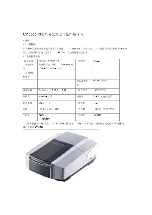
UV-2600型紫外分光光度计操作指导书1概况仪器概况:UV-2600型紫外分光光度计是由日本岛津(Shimadzu)生产制造,与功能强大的操作软件UVProbe结合,操作简单方便,且符合SH/T0181方法的测量精度要求。
主要技术参数光源50W卤素灯、氘灯单色器切尼尔-特纳单色器主电压AC100V~240V主频率50/60Hz使用条件操作温度:15~35℃操作湿度:30%~805%2仪器结构仪器由UV-2600型紫外分光光度计和计算机组成。
3操作步骤开机在使用前先确认仪器和计算机的工作电源,检查仪器样品室应无遮挡光路的物品。
确认后先开启计算机,然后开启仪器电源。
待分光光度计外侧的指示灯显示绿色时,启动电脑桌面上的UVPROBE程序。
首先从下拉式菜单的仪器项上追加需要的仪器,操作完毕如下图①所示,然后点击上图的连接键②,这样仪器与计算机连接(当然,中间的通讯电缆的连接、通讯口的指定等都是必须的,此处不再赘述)并开始下示的初始化面。
初始化大约需要5分钟左右,进行一系列的检查和初置,如一切顺利通过就可以开始测定。
测定首先选择测定的方式,在主菜单上能发现右图所示的各键,自左至右分别为:①报告生成器:用于制作各种格式的报告。
②动力学测定方式:一般测定吸收值随时间的变化,通常用于酶反应随时间的变化。
③光度测定(定量)方式:可进行多波长、单波长、峰高或峰面积定量。
校准曲线可使用多点、单点、K因子等方法。
由于具有自定义方程的功能,DNA/蛋白质测定等以前需要特殊选购的软件才能进行的工作,使用UVPROBE可自编程序进行测定。
④光谱测定方式:可进行紫外可见区的光谱测定。
光谱测定方式3.3.1参数的设定点击菜单栏上的键,即可出现如下图所示的选择测定条件的画面:在此对话框中可选择波长测定的范围、扫描的速度、采样间隔等条件。
点击图中[试样准备]标签,可输入重量、体积、稀释因子、光程长等信息。
点击图中[仪器参数]标签,可选择测定种类(吸收值、透射率、能量、反射率)以及通带(狭逢)等条件。
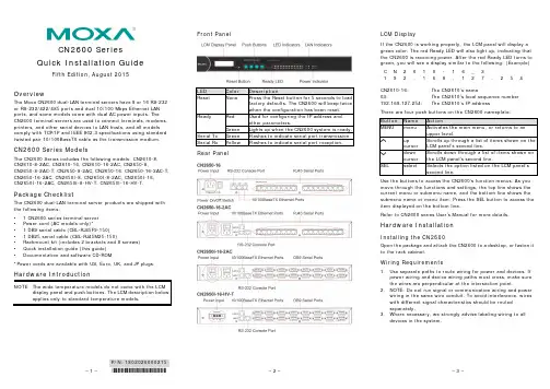
– 1 –– 2 –– 3 –P/N: 1802026000215*1802026000215*CN2600 Series Quick Installation GuideFifth Edition, August 2015OverviewThe Moxa CN2600 dual-LAN terminal servers have 8 or 16 RS-232 or RS-232/422/485 ports and dual 10/100 Mbps Ethernet LAN ports, and some models come with dual AC power inputs. The CN2600 terminal servers are used to connect terminals, modems, printers, and other serial devices to LAN hosts, and all models comply with TCP/IP and IEEE 802.3 specifications using standard twisted pair 10/100BaseTX cable as the transmission medium.CN2600 Series ModelsThe CN2600 Series includes the following models: CN2610-8, CN2610-8-2AC, CN2610-16, CN2610-16-2AC, CN2650-8,CN2650-8-2AC-T, CN2650-8-2AC, CN2650-16, CN2650-16-2AC-T, CN2650-16-2AC, CN2650I-8, CN2650I-8-2AC, CN2650I-16, CN2650I-16-2AC, CN2650I-8-HV-T, CN2650I-16-HV-T.Package ChecklistThe CN2600 dual-LAN terminal server products are shipped with the following items: • 1 CN2600 series terminal server • Power cord (AC models only)*• 1 DB9 serial cable (CBL-RJ45F9-150) • 1 DB25 serial cable (CBL-RJ45M25-150)• Rackmount kit (includes 2 brackets and 8 screws) • Quick installation guide (this guide) •Documentation and software CD-ROM*Power cords are available with US, Euro, UK, and JP plugs.Hardware IntroductionNOTE The wide temperature models do not come with the LCM display panel and push buttons. The LCM description below applies only to standard temperature models.Front PanelRear PanelLCM DisplayIf the CN2600 is working properly, the LCM panel will display a green color. The red Ready LED will also light up, indicating that the CN2600 is receiving power. After the red Ready LED turns to green, you will see a display similar to the following: (Example) C N 2 6 1 0 - 1 6 _ 3 192.168.127.254CN2610-16: The CN2610’s name03:The CN2610’s local sequence number192.168.127.254:The CN2610’s IP addressThere are four push buttons on the CN2600 nameplate:Use the buttons to access the CN2600’s function menus. As you move through the functions and settings, the top line shows the current menu or submenu name, and the bottom line shows the submenu name or menu item. Press the SEL button to access the item displayed on the bottom line.Refer to CN2600 series User’s Manual for more details.Hardware InstallationInstalling the CN2600Open the package and attach the CN2600 to a desktop, or fasten it to the rack cabinet.Wiring Requirements1. Use separate paths to route wiring for power and devices. Ifpower wiring and device wiring paths must cross, make sure the wires are perpendicular at the intersection point.2. NOTE: Do not run signal or communication wiring and powerwiring in the same wire conduit. To avoid interference, wires with different signal characteristics should be routed separately.3. Where necessary, we strongly advise labeling wiring to alldevices in the system.– 4 – – 5 – – 6 –/supportThe Americas: +1-714-528-6777 (toll-free: 1-888-669-2872)Europe: +49-89-3 70 03 99-0 Asia-Pacific: +886-2-8919-1230China: +86-21-5258-9955 (toll-free: 800-820-5036)2015 Moxa Inc., All Rights ReservedConnecting the PowerAC: Connect the CN2600 100-240 VAC power line with its ACconnector. If the power is properly supplied, the “Ready” LED will show a solid red color until the system is ready, at which time the “Ready” LED will change to a green color.DC: Connect the NPort CN2650I-HV’s power cord to the DC connector, and then follow the steps given below:Take the CN2650I-8-HV-T as an example. Loosen the screws on the V+ and V- terminals of the CN2650I-8-HV-T terminal block. Connect the power cord’s 100 VDC wire to the terminal block’s V+ terminal, and the power cord’s DC Power Ground wire to the terminal block’s V- terminal, and then tighten the terminal block screws. (Note: The CN2650I-8-HV-T can still operate even if the DC Power Ground wires are reversed.) The “Ready” LED will show a solid red color until the system is ready, at which time it will change to a green color.Grounding the CN2650I-HV:Grounding and wire routing help limit the effects of noise due to electromagnetic interference (EMI). Run the ground connection from the ground screw to the grounding surface prior toconnecting devices. The Shielded Ground(sometimes called Protected Ground) contact is the second contact from the right of the 5-pin power terminal block connector located on the rear panel of the CN2650I-8-HV-T. Connect the SG wire to the Earth ground.Connecting to the NetworkUse an Ethernet cable to connect the CN2600 to the Ethernet network. There are 2 LED indicators located on the top left and right corners of the Ethernet connector. If the cable is properly connected, the CN2600 will indicate a valid connection to the Ethernet in the following ways:The top right corner LED indicator maintains a solid green color when the cable is properly connected to a 100 Mbps Ethernet network.The top left corner LED indicator maintains a solid orange color when the cable is properly connected to a 10 Mbps Ethernet network.Connecting to a Serial DeviceConnect the serial data cable between the CN2600 and the serialdevice.Connecting to a ConsoleA console is a combination of keyboard and monitor, and is used to configure settings and to monitor the status of your system. If you do not have a network environment, use a terminal, a PC running UNIX, or a PC with terminal emulation software (e.g., HyperTerminal in Windows; PComm by Moxa). Use anRJ45-to-DB25 or RJ45-to-DB9 cable to connect the terminal to the console socket. Refer to the CN2600 User’s Manual for more details.Software InstallationEntering the Console UtilityThe Console Utility is the main application needed to set up theserver/port configuration, and to execute utilities such as ping, diagnosis, monitor, and upgrade. There are two ways to enter the Console Utility. One is to use terminal emulation through a console terminal, and the other is to telnet from a network terminal. Refer to the CN2600 User’s Manual for more details.Pin Assignments and Cable Wiring。
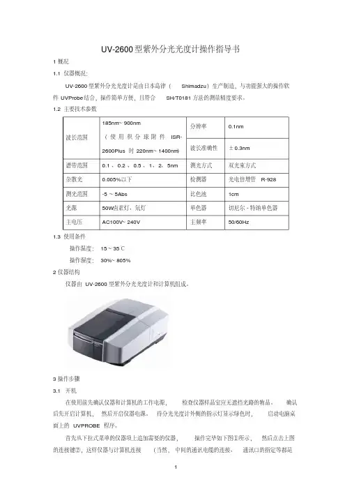
UV-2600 型紫外分光光度计操作指导书1概况1.1 仪器概况:UV-2600 型紫外分光光度计是由日本岛津( Shimadzu )生产制造,与功能强大的操作软件UVProbe 结合,操作简单方便,且符合SH/T0181 方法的测量精度要求。
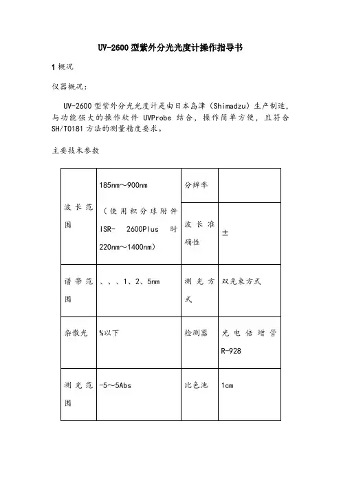
1.2 主要技术参数波长范围185nm~ 900nm ISR- 分辨率0.1nm图象面板分球附件使(用积2600Plus 时①220nm~ 1400nm)①定期维护检查表波长准确性0.3nm ±列名②谱带范围2、5nm 、、 0.10.2 、 0.51 、测光方式双光束方式杂散光0.005% 以下检测器R-928 光电倍增管测光范围5Abs ~ -5 比色池1cm光源卤素灯、氘灯 50W 单色器切尼尔 - 特纳单色器主电压240V 主频率50/60Hz~ AC100V1.3 使用条件 15 操作温度:~℃ 35805% 操作湿度: 30%~仪器结构 2 型紫外分光光度计和计算机组成。
仪器由 UV-2600操作步骤 3 开机 3.1确认检查仪器样品室应无遮挡光路的物品。
在使用前先确认仪器和计算机的工作电源,启动电脑桌待分光光度计外侧的指示灯显示绿色时,然后开启仪器电源。
后先开启计算机,UVPROBE 面上的程序。
然后点击上图首先从下拉式菜单的仪器项上追加需要的仪器,操作完毕如下图①所示,通讯口的指定等都是(当然,的连接键②,这样仪器与计算机连接中间的通讯电缆的连接、1必须的,此处不再赘述)并开始下示的初始化面。
⑧①⑨②⑩③⑾④⑿⑤⒀⑥⒁⑦如一切顺利通过就可以开始测 5 分钟左右,进行一系列的检查和初置,初始化大约需要定。
3.2测定首先选择测定的方式,在主菜单上能发现右图所示的各键,自左至右分别为:①报告生成器:用于制作各种格式的报告。
②动力学测定方式:一般测定吸收值随时间的变化,通常用于酶反应随时间的变化。
③光度测定(定量)方式:可进行多波长、单波长、峰高或峰面积定量。

分光測色計中文操作手冊制定:TOMMY 日期:2004/05/18第三次修订本操作環境:•應在外界溫度從5℃到40℃的環境中使用, 不能在溫度變化迅速的環境中使用.•不可以把儀器直接置於太陽底下或放在火爐附近.•不可以在吸煙、有灰塵及有化學氣體的環境下使用儀器.•不能在有強磁性的環境下使用儀器.•不能在海拔2000m以上地方使用儀器.•CM-2600d/2500d是一室內用測試儀器, 不應在室外使用.白色校正板:•由於白板數據是在溫度23℃時測量得到的, 所以爲了得到更高精度的測量資料, 白板校正和測量應在溫度23℃左右進行.•保護好白板不能被刮傷或污染.•白板不用時請蓋好.孔徑:•不要用手去碰孔徑的內表面, 不要刮傷或弄髒它.•不用時把它放在白板校正盒中的孔徑存放處.電源:•在儀器不用時一定記得要關閉儀器電源開關.•要經常用變壓器(AC-A17)來供電.系統:•不能讓儀器受到巨烈的撞擊或振動.•爲了使儀器的積分球及測量孔免受污染, 在儀器不用時記得把儀器放置在白板校正盒上.•不能在電視機、收錄機等電器設備旁使用, 否則儀器會受到干擾.備用電池:•儀器中測量之資料及各個設定的存儲都依賴於儀器內的備用電池, 備用電池充足電後可一次性保存記憶體中內容4.5個月, 充電時需5個小時才能充足.•CM-2600d/2500d必須存放在溫度從0℃到45℃, 濕度小於80%的環境中. •不能把CM-2600d/2500d放在汽車或汽車的尾箱中, 也不能直接放在太陽底下.•不能把CM2600d/2500d放在吸煙、有灰塵和有化學氣體的環境中.•不要讓灰塵進入到積分球中, 否則會影響儀器測量的精確度.•在不用儀器時記得把白板蓋好以免白板變色.•在不用儀器時記得把孔徑放在一個不直接見光的地方.•在運輸時記得把儀器放入到盒子中.•如果在兩周或更長時間不用儀器時, 記得把電池取出.清潔注意事項:•不能用化學試劑如酒精或苯來擦儀器, 只能用幹凈、柔軟的幹布來擦. •如果白板被污染, 同樣用幹凈、柔軟之幹布拭擦; 如果無法清潔污點, 請聯系美能达公司或专业人员.•當孔徑內表面或積分球被弄髒後, 請聯系本公司.•當CM-2600d/2500d被摔壞時, 請不要自已拆卸, 勿必請聯系本公司或请专业技术人员维修.第一部分 使用前的準備標準配件:•白色校正板CM-A145•標準孔徑CM-A146(ψ8mm) CM-A147(ψ3mm)備註:CMA146用於CN-2600d/2500dCM-A147只用於CM-2600d•變壓器 AC-A17輸入電壓:100到240 V ac(50/60Hz)輸出電壓:5 V dc 2.8A•RS-232C 通訊線 IF-A16※ 線長2米•AA 型號電池(×4)可選配件:(无特别要求,需要单独购买)•零點校正盒CM-A32•手提箱CM-A148•CM-A149•色彩品質控制軟體“Spectra Magic”(CM-S9W)版本V3.2或更高•印表機通訊線CR-A75功能介紹:1.觀物鏡※通過觀物鏡可以看清所測物.品的位置是否放置正確.2.觀物鏡開關※用來打開/關閉觀物鏡.備註: 當觀物鏡被打開時, 測量就無法進行.3.功能鍵※向左或向右旋轉此功能鍵可選擇所需的功能, 當選定好了後按下此鍵即可確定.4.LCD顯示屏5.樣品測量孔※CM-2600d可通過更換孔徑來改變測量孔徑的大小.6.測量孔徑選擇開關※CM-2500d型號分光儀無此開關.7.測量鍵. 8. 資料輸出埠.9.電池蓋. 10. 變壓器插孔.11.電源開關.白色校正板CM-A1451.蓋子*用來保護白板2.白色校正板*在白板不用時記得用蓋子蓋住3.孔徑存放處*用於存放不用的孔徑準備工作孔徑的安裝及取下一. 安裝孔徑1.把測量孔徑放在測量孔上, 讓孔徑上突出的插銷對準積分球上的標志2.按積分球上指示方向旋動孔徑, 直到旋不動爲止二. 取下孔徑1. 按積分球上指示方向相反的方向旋動孔徑, 直到旋不動爲止2. 取下孔徑即可孔徑的存放備註: 2600D在儀器的白色校正板CM-A145上有一個用於存放不用之孔徑的裝置,三. 存放孔徑把孔徑放在孔徑存放的裝置上,然後順時針旋轉孔徑直到旋不動爲止四. 取下孔徑先逆時針旋轉孔徑直到旋不動爲止, 再取下孔徑清潔一.白色校正板※當白色校正板弄髒後請用柔軟的幹布或透鏡清潔液來清潔二.孔徑※用噴氣球把孔徑上灰塵吹幹凈三.積分球1.把觀物鏡開關打開2.取下孔徑3.用噴氣球把積分內的灰塵吹幹凈*當積分球中的臟點用噴球無法吹幹凈時請聯联系美能达。
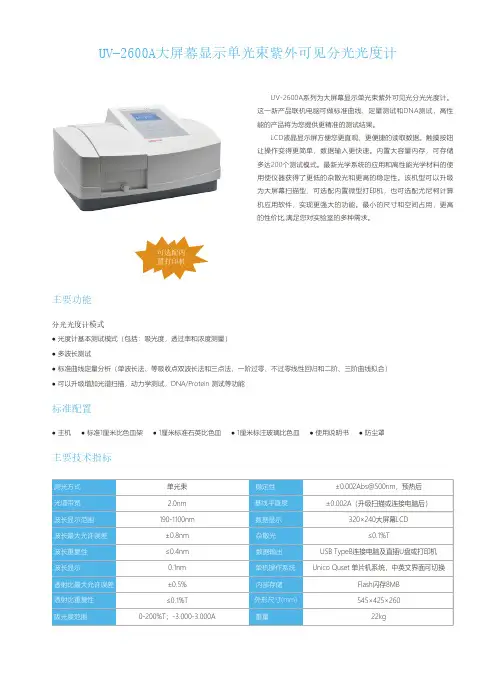
UV-2600A大屏幕显示单光束紫外可见分光光度计
● 光度计基本测试模式(包括:吸光度,透过率和浓度测量)● 多波长测试
● 标准曲线定量分析(单波长法、等吸收点双波长法和三点法,一阶过零、不过零线性回归和二阶、三阶曲线拟合)● 可以升级增加光谱扫描,动力学测试,DNA/P r otein 测试等功能
分光光度计模式
主要功能
● 主机
● 标准1厘米比色皿架
● 1厘米标准石英比色皿
● 1厘米标注玻璃比色皿
● 使用说明书
● 防尘罩
标准配置
主要技术指标
可选配内置打印机
UV-2600A系列为大屏幕显示单光束紫外可见光分光光度计。
这一新产品联机电脑可做标准曲线、定量测试和DNA测试,高性能的产品将为您提供更精准的测试结果。
LCD液晶显示屏方便您更直观、更便捷的读取数据。
触摸按钮让操作变得更简单,数据输入更快速。
内置大容量内存,可存储多达200个测试模式。
最新光学系统的应用和高性能光学材料的使用使仪器获得了更低的杂散光和更高的稳定性。
该机型可以升级为大屏幕扫描型,可选配内置微型打印机,也可选配尤尼柯计算机应用软件,实现更强大的功能。
最小的尺寸和空间占用,更高的性价比,满足您对实验室的多种需求。

xYJ2600使用说明书
XYJ2600系列多媒体集中控制器简介:信源XYJ2600系列多媒体集中控制器是在系列中控基础上,结合学校对多媒体教学的特殊要求增加许多实用功能而最新推出的。
它集投影机展示台、银幕、台式电脑、笔记本电脑的控制于一身,高性能VGA切换分配(台式电脑、笔记本电脑、数码展示台等3路进2路分配输出,其中电脑显示器独立显示台式电脑内容),音视频切换(3路AV输入1路AV输出),话筒输入,话筒数字音量控制,一键开启电脑等,功能简洁明了。
使用做到一键通(B型,投影机开机,银幕自动下降,关闭电源,投影机自动关机、散热,银幕自动上升,延时切断电源)。
面板上还集成有网络接口、USB接口、电源插口,给用户使用带来极大方便。
一、安装调试指南
安装XYJ2600多媒体集中控制器的安装非常方便,只要按以下接线图连接即可。
二、调试
投影机红外控制码的写入(XYJ2600-A型)因为各厂家投影机的控制码各不相同,所以必须首先对投影机的控制码进行学习以便控制投影机。
三、红外控制码清除方法
如果需要清除学习的控制码,按一下(清除)按键,此时面板指示灯闪亮,进入删除状态。
再按一下要删除的功能键,此时学码指示
灯也同时开始闪亮(功能键中没有保存控制码时,学码指示灯不会亮),再按一下(清除)键即可清除此功能控制码,面板指示灯此时又开始闪亮,可继续清除其它功能键。
要想退出清除状态,再按一下(清除)键即可。
四、提示
为了使控制码学习顺利,请将第一个要学习的功能键学习两遍。
五、注
对于有些需按下投影机POWER键三秒以上才能关机的,请选用
RS232串口控制的XYJ2600-B型多媒体集中控制器。
UV-2600系列紫外可见分光光度计操作规程1 目的规范UV-2600紫外可见分光光度计的操作、使用、保养和维护,以延长仪器设备寿命,保证设备和操作人员的安全,使检验结果准确可靠。
2 适用范围适用于本公司UV-2600紫外可见分光光度计(尤尼可(上海)仪器有限公司)的使用操作。
3 职责3.1操作人员:按本操作规程操作仪器,对仪器进行日常维护,作使用登记。
3.2保管人员:负责监督仪器操作是否符合规程,对仪器进行定期维护、保养。
3.3计量检定员:负责该仪器的周期检定计划及实施。
3.4科室负责人:负责仪器综合管理。
4 仪器设备性能技术指标4.1波长范围:190nm~1100nm4.2波长精度:±0.8nm4.3波长重复性:0.2nm4.4光谱带宽:4nm,4.5杂散光:0.05%T( 220nm,340nm)4.6数据显示:320x240图行液晶显示器4.7光度方式:透过率、吸光度、反射率、能量4.8光度范围:0-200% -0.3-3.0A0-9999C(0-9999F)4.9光度精度:0.3%T4.10基线直线性:±0.002 A4.11稳定性:±0.002A/小时@500nm(预热1小时后)5 安全操作注意事项5.1本仪器必须设专人管理,实行专管共用,使用人员必须经专门培训后方可上机操作。
5.2仪器正常使用环境:室内空气流通、清洁、干燥(使用温度为5℃—35℃)、无腐蚀性气体、避免直射日光的照射。
5.3严格遵守操作规程,如仪器出现故障应马上切断电源,立即向管理人员或科室负责人报告,查明原因及时修理,不得擅自“修理”,如需修理,须及时向领导报告,并作好使用和故障情况登记及实验记录。
5.4不得在仪器室内制作和储存样品。
5.5注意仪器的清洁卫生,应定期更换干燥剂。
5.6严禁频繁开关机,以免损坏电源。
供给仪器的电源为220伏±10%,49.5—50HZ,并必须装有良好的接地线。
PT2cn-1631炉内气体监测仪SD-2600使用说明书(PT2-163)(PT2E-163)邮编:174-8744东京都板桥区小豆泽2-7-6主页:https://www.rikenkeiki.co.jp/使用注意事项本仪器是气体警报器,有检测大气中的可燃性气体并发出警报的功能。
气体警报器是安全仪器,不是对气体进行定量、定性分析、测量的分析仪或浓度计。
使用时,请充分理解以下几点,正确使用仪器。
1.本仪器会受到待检测气体以外的气体、蒸气的干扰。
请注意干扰造成的警报动作。
另外,安装场所的环境变化(温度・湿度等)也可能造成变动。
2.请在适合仪器性能的范围内使用警报设置。
对于符合高压气体安全法的设备,如果警报设置低于本公司标准警报设置值时,可能引起误警报。
3.本仪器是安全仪器,不是控制仪器。
请将本仪器的警报触点输出用于外部警报灯・蜂鸣器,将模拟信号输出用于指示计或者外部记录仪。
用于除此以外的控制时,本公司对误动作等引起的补偿概不负责。
4.本仪器使用的气体检测传感器的气体感应部是在金属的多孔质烧结体中浸渗氧化催化剂而成。
如果烧结体表面附着硅酮或硫化物,可能导致气体感应部面积减小,灵敏度大幅降低。
在安全管理上,无论多么微量,请避免在硅酮或硫化物存在的情况下使用本仪器。
5.维护本仪器时需要进行定期检查,包括使用说明书中记载的定期更换部件的更换调整。
由于是安全仪器,推荐根据法规每6个月进行定期检查及气体校正。
目录1.产品概要 (1)1-1.前言 (1)1-2.使用目的 (1)1-3.危险、警告、注意、注记的定义 (1)1-4.标准及防爆规格的确认方法 (1)2.安全上的重要事项 (2)2-1.危险事项 (2)2-2.警告事项 (2)2-3.注意事项 (3)2-4.安全信息 (4)3.产品组成 (5)3-1.主机及标准附件 (5)3-2.各部名称与作用 (6)3-3.框图 (7)4.使用方法 (8)4-1.使用时 (8)4-2.与安装场所有关的注意事项 (8)4-3.系统设计上的注意事项 (9)4-4.安装方法 (10)4-5.配线方法 (11)5.操作方法 (17)5-1.启动准备 (17)5-2.基本动作流程 (17)5-3.启动方法 (18)5-4.关于各种模式 (19)5-5.用户模式 (20)5-6.结束方法 (22)6.各种动作及功能 (23)6-1.气体警报动作 (23)6-2.故障警报动作 (24)6-3.外部输出动作 (25)6-4.关于各种功能 (26)7.保养检查 (27)7-1.检查的频度与检查项目 (27)7-2.定期检查模式 (28)7-3.气体校正方法 (35)7-4.更换部件 (37)8.关于储存、移机及废弃 (38)8-1.储存或长期不使用时的处理 (38)8-2.移机或者重新使用时的处理 (38)8-3.产品的废弃 (38)9.故障排除 (39)10.产品规格 (40)10-1.规格一览 (40)10-2.附件一览 (41)10-3.检测原理 (42)11.术语的定义 (43)3-3.框图<电气系统图>7<零位调整“1-1”>进行零位调整时使用。
UV-2600型紫外分光光度计操作指导书1概况 1.1仪器概况:UV-2600型紫外分光光度计是由日本岛津(Shimadzu )生产制造,与功能强大的操作软件UVProbe 结合,操作简单方便。
1.2主要技术参数1.3使用条件操作温度:15~35℃ 操作湿度:30%~80% 2仪器结构仪器由UV-2600型紫外分光光度计和计算机组成。
3操作步骤 3.1 开机在使用前先确认仪器和计算机的工作电源已连接好,检查仪器样品室应无遮挡光路的物品,样品室盖关闭。
确认后先开启计算机,然后开启仪器电源(仪器右下侧的power 键,开关按到“1”侧表示打开),等待仪器自检(自检时不开盖),大约5分钟后,听到嘟嘟嘟声表示自检完毕,自检过程中分光光度计外侧的指示灯状态为红灯闪烁到绿灯闪烁,最终显示为绿灯不闪烁。
3.2 连接软件:双击电脑上的UVProbe 图标,打开UVProbe 软件,出现以下图示,点击上图中的“连接”,并开始如下图的初始化界面。
初始化大约需要5分钟左右,仪器自动进行一系列的检查和初置,如一切顺利通过(图上的通过栏为绿色)点击“确定”,出现下图界面。
但是如果检测出现异常则上述图例出现红色显示并停止初始化。
确认“失败”项目后关闭(off )电源,再次确认样品室无遮挡光路的物品,样品室盖关闭后,重新打开电源(on )。
① ② ③ ④ ⑤ ⑥ ⑦⑨ ⑩ ⑾ ⑿⑧“仪器控制按键”栏(连接)“仪器状态”栏即进入通讯状态的测试模式,此时[连接])变为[断开],在[仪器状态]栏显示当前波长和光度值。
4 测定首先选择测定的方式,在主菜单上能发现右图所示的各键,自左至右分别为:①报告生成器:用于制作各种格式的报告。
②动力学测定方式:测定固定波长光度值的时间变化过程(时间过程扫描测定)。
也可计算酶的活性值等。
③光度测定(定量)方式:测定(光度测定)一点或多点波长的光度值。
还具备使用各种工作曲线法(多点工作曲线、单点工作曲线、K系数法)的定量功能。
ltd2600探地雷达使用手册LTD2600探地雷达是一种先进的地下探测设备,旨在帮助用户准确、高效地探测地下的各种目标,如金属物体、地下管道和地下障碍物等。
本使用手册将详细介绍LTD2600探地雷达的功能、使用方法以及注意事项,以帮助用户正确操作并获取最佳的探测结果。
一、产品概述1. LTD2600探地雷达是一款采用雷达技术的地下探测设备。
2. 主要用途:寻找地下金属物体、地下管道以及地下障碍物。
3. 特点:高精度、高效率、易操作、可靠性高。
二、功能介绍1. 探测地下金属物体:LTD2600探地雷达能够准确识别和定位地下金属物体,如金属管道、地下电缆等。
2. 探测地下管道:通过LTD2600探地雷达,用户可以轻松探测地下水管、天然气管道等管线。
3. 探测地下障碍物:不仅能够识别金属物体,LTD2600探地雷达还具备探测非金属障碍物(如混凝土、塑料等)的能力。
三、使用方法1. 准备工作a. 确保LTD2600探地雷达电池已充电或已连接外部电源。
b. 确保探测传感器已正确安装并与设备连接良好。
c. 打开电源,并等待设备初始化完成。
2. 参数设置a. 根据具体需求,选择适当的探测模式(金属物体、管道或障碍物)。
b. 根据地下环境的复杂程度,调整扫描深度。
3. 开始探测a. 将LTD2600探地雷达置于地面上,并缓慢移动,确保完整覆盖需要探测的区域。
b. 观察控制面板上的指示器,当出现信号强度变化时,表明有目标存在。
c. 当设备发出声音或显示目标图形时,说明成功探测到地下目标。
4. 数据分析a. 将探测到的数据传输到计算机或移动设备上进行进一步分析。
b. 根据分析结果,确定目标的确切位置和性质。
四、注意事项1. 使用LTD2600探地雷达前,请仔细阅读并遵守本使用手册的操作指南。
2. 在使用设备时,应确保周围环境安全,避免对他人和自身造成伤害。
3. 避免在恶劣天气条件下使用,以免影响设备性能和探测效果。
ltd2600探地雷达使用手册概述及解释说明1. 引言1.1 概述本手册是针对LTD2600探地雷达的使用进行详细说明和解释的指南。
探地雷达是一种重要的地质勘察仪器,用于探测地下物体的位置、形状和性质。
本手册将提供有关该设备的介绍、操作步骤以及使用过程中需要注意的事项。
1.2 文章结构文章主要分为以下几个部分:引言、LTD2600探地雷达介绍、使用前的准备工作、LTD2600探地雷达的操作步骤以及结论与建议。
每个部分都会逐一介绍并深入讨论相关内容,以帮助读者全面了解和正确使用LTD2600探地雷达。
1.3 目的撰写本手册的目的是为了帮助用户更好地理解和操作LTD2600探地雷达。
通过阅读本手册,用户可以了解到该设备的基本原理、功能特点和技术应用领域,并能够按照正确步骤进行设备启动、数据采集与处理以及实时监测和显示功能操作。
此外,在结论与建议部分,我们还将总结使用体验并提供针对不同环境优化建议,同时展望探地雷达技术未来的发展趋势。
以上为“1. 引言”部分的内容,供参考。
2. LTD2600探地雷达介绍2.1 设备概述LTD2600探地雷达是一种高性能地质勘探设备,具有先进的技术原理和广泛的应用领域。
该雷达采用无线传输技术,能够在各种复杂的地质环境中快速、准确地检测地下目标,并提供可靠的数据分析结果。
2.2 技术原理LTD2600探地雷达基于电磁波传播和反射原理进行工作。
通过发射电磁波束并接收反射信号,它可以分析信号之间的时间差和强度变化,从而确定目标物体的位置、形状和性质。
该雷达使用了先进的数字信号处理算法,提供了出色的深度探测性能和高分辨率。
2.3 应用领域LTD2600探地雷达广泛应用于以下领域:1. 地质勘探:在石油、天然气等资源勘探中,LTD2600能够帮助寻找潜在的油气层或矿藏。
2. 建筑工程:在建筑施工前,使用LTD2600可以检测到潜在的地下障碍物,如管线、地下设施等,以避免施工事故和损失。