备考2014年全国高中物理竞赛---ipho_Problems71
- 格式:doc
- 大小:43.01 KB
- 文档页数:3

2014 第 31 届全国中学生物理竞赛预赛试题及参考答案与评分标准一、选择题.本题共 5 小题,每小题 6 分,在每小题给出的 4个选项中,有的小题只有一项符合题意,有的小题有多项符合题意.把符合题意的选项前面的英文字母写在每小题后面的方括号内,全部选对的得 6 分,选对但不全的得 3 分,有选错或不答的得 0分.1.一线膨胀系数为α的正立方体物块,当膨胀量较小时,其体膨胀系数等于A.α1/3B.α3C.αD. 3α2.按如下原理制作一杆可直接测量液体密度的秤,称为密度秤,其外形和普通的杆秤差不多,装秤钩的地方吊着一体积为 lcm 3的较重的合金块,杆上有表示液体密度数值的刻度.当秤砣放在 Q 点处时秤杆恰好平衡,如图所示,当合金块完全浸没在待测密度的液体中时,移动秤砣的悬挂点,直至秤杆恰好重新平衡,便可直接在杆秤上读出液体的密度.下列说法中错误的是A.密度秤的零点刻度在Q 点B.秤杆上密度读数较大的刻度在较小的刻度的左边C.密度秤的刻度都在Q 点的右侧D.密度秤的刻度都在Q 点的左侧3.一列简谐横波在均匀的介质中沿z 轴正向传播,两质点P1和 P2的平衡位置在 x 轴上,它们相距 60cm,当 P1质点在平衡位置处向上运动时,P2质点处在波谷位置,若波的传播速度为 24 m/s,则该波的频率可能为A. 50Hz B . 60HzC. 400Hz D . 410Hz4.电磁驱动是与炮弹发射、航空母舰上飞机弹射起飞有关的一种新型驱动方式,电磁驱动的原理如图所示,当直流电流突然加到一固定线圈上,可以将置于线圈上的环弹射出去.现在同一个固定线圈上,先后置有分别用钢、铝和硅制成的形状、大小和横截面积均相同的三种环;当电流突然接通时,它们所受到的推力分别为F1、F2和 F3.若环的重力可忽略,下列说法正确的是A. F1>F 2>F3B. F2 >F3 >F1C. F3 >F 2> F 1 D . F1=F2=F35.质量为 m A的 A 球,以某一速度沿光滑水平面向静止的 B 球运动,并与B 球发生弹性正碰.假设 B 球的质量m B可选取为不同的值,则A.当 m B=m A时,碰后 B 球的速度最大B.当 m B =m A时,碰后 B 球的动能最大C.在保持m B>m A的条件下, m B越小,碰后 B 球的速度越大D.在保持 m B<m A的条件下, m B越大,碰后 B 球的动量越大二、填空题.把答案填在题中的横线上,只要给出结果,不需写出求得结果的过程.6.( 10 分)用国家标准一级螺旋测微器(直标度尺最小分度为0.5mm,丝杆螺距为0.5mm,套管上分为 50 格刻度)测量小球直径.测微器的初读数如图(a)所示,其值为 _____mm,测量时如图 (b) 所示,其值为_____mm ,测得小球直径d=___________mm .7.( 10 分)为了缓解城市交通拥问题,杭州交通部门在禁止行人步行的十字路口增设“直行待区”(行人可从天桥或地下过道过马路),如图所示.当其他车道的车辆右拐时,直行道上的车辆可以提前进入“直行待行区”;当直行绿灯亮起时,可从“直行待行区”直行通过十字路口.假设某十字路口限速50km/h ,“直行待行区”的长度为12m,从提示进入“直行待行区”到直行绿灯亮起的时间为4s.如果某汽车司机看到上述提示时立即从停车线由静止开始匀加速直线运动,运动到“直行待行区”的前端虚线处正好直行绿灯亮起,汽车总质量为 1.5t ,汽车运动中受到的阻力恒为车重的0.1 倍,则该汽车的行驶加速度为_________;在这4s 内汽车发动机所做的功为 _____________ (取 g=10m/s2)8.( 10 分)如图所示,两个薄透镜L 1和 L2共轴放置,已知 L 1的焦距 f 1=f ,L 2的焦距 f 2=―f ,两透镜间的距离也是f,小物体位于物面 P 上,物距 u1=3f .(1)小物体经过这两个透镜成的像在L 2的 _____边,到 L2的距离为 ________,是 ______像(填“实”或“虚”)、 _______像(填“正”或“倒”),放大率为 ___________.(2)现把两个透镜位置调换,若还要使给定的原物体在原像处成像,两透镜作为整体应沿光轴向 ______边移动距离 _________.这个新的像是 ______(填“实”或“虚”)、______像(填“正”或“倒”),放大率为 __________ .9.(10 分 )图中所示的气缸壁是绝热的.缸内隔板 A 是导热的,它固定在缸壁上.活塞 B 是绝热的,它与缸壁的接触是光滑的,但不漏气. B 的上方为大气. A 与B之间以及 A 与缸底之间都盛有n mol 的同种理想气体,系统在开始时处于平衡状态.现通过电炉丝 E 对气体缓慢加热,在加热过程中,A、 B 之间的气体经历____过程. A 以下气体经历____过程;气体温度每上升1K, A、 B 之间的气体吸收的热量与 A 以下气体净吸收的热量之差等于_____.已知普适气体常量为R.10.( 10 分)字宙空间某区域有一磁感应强度大小为B=1.0 ×10⁻⁹ T 的均匀磁场,现有一电子绕磁力线做螺旋运动.该电子绕磁力线旋转一圈所需的时间间隔为_____s;若该电子沿磁场方向的运动速度为 1.0 ×10⁻²c(c 为真空中光速的大小),则它在沿磁场方向前进 1.0 ×10⁻³ 光年的过程中,绕磁力线转了 _____圈. 已知电子电荷量为 1.60 ×10 -19C,电子质量为 9.11 ×10⁻³¹kg .三、计算题,计算题的解答应写出必要的文字说明、方程式和重要的演算步骤,只写出最后结果的不能得分.有数值计算的,答案中必须明确写出数值和单位.11.( 15 分)如图所示,一水平放置的厚度为t 折射率为 n 的平行玻璃砖,下表面镀银(成反射镜).一物点 A 位于玻璃砖的上方距玻璃砖的上表面为h 处.观察者在 A 点附近看到了A 点的像. A 点的像到 A 点的距离等于多少?不考虑光经玻璃砖上表面的反射.12.( 20 分)通常电容器两极板间有多层电介质,并有漏电现象.为了探究其规律性,采用如图所示的简单模型,电容器的两极板面积均为A.其间充有两层电介质l 和 2,第 1 层电介质的介电常数、电导率(即电阻率的倒数)和厚度分别为ε、σ和 d ,第 2 层电介质的111则为ε、σ和 d .现在两极板加一直流电压U,,电容器处于稳定状态.222(1)画出等效电路图;(2)计算两层电介质所损耗的功率;(3)计算两介质交界面处的净电荷量;提示:充满漏电电介质的电容器可视为一不漏电电介质的理想电容和一纯电阻的并联电路.13. (20 分 )如图所示,一绝缘容器内部为长方体空胶,其长和宽分别为 a 和 b,厚度为 d,其两侧等高处装有两根与大气相通的玻璃管(可用来测量液体两侧的压强差).容器内装满密度为ρ的导电液体,容器上下两端装有铂电极 A 和 C,这样就构成了一个液体电阻,该液体电阻置于一方向与容器的厚度方向平行的均匀恒定的磁感应强度为 B 的磁场中,并通过开关 K 接在一电动势为ε、内阻为 r 的电池的两端,闭合开关.若稳定时两侧玻璃管中液面的高度差为 h,求导电液体的电导率σ.重力加速度大小为 g.14.( 20 分) lmol 的理想气体经历一循环过程l— 2— 3—1,如 p— T 图示所示.过程l — 2 是等压过程,过程3— 1是通过 p — T图原点的直线上的一段,描述过程 2 — 3的方程2为 c1p + c2p =T ,式中 c1和 c2都是待定的常量, p 和 T 分别是气体的压强和绝对温度.已知,气体在状态 l 的压强、绝对温度分别为p1和 T1.气体在状态 2 的绝对温度以及在状态 3 的压强和绝对湿度分别为T 2以及 p3和 T3.气体常量 R 也是已知的.(1)求常量 c1和 c2的值;(2)将过程 l— 2— 3— 1 在 p—V 图示上表示出来;(3)求该气体在一次循环过程中对外做的总功.15. (20 分 )一个ω介子飞行时衰变成静止质量均为m 的三个π介子,这三个π介子的动量共面.已知:衰变前后介子运动的速度都远小于光在真空中的速度c;衰变后的三个π介子的动能分别为T 1、 T2和 T 3,且第一、二个π介子飞行方向之间的夹角为θl,第二、三个π介子飞行方向之间的夹角为θ(2如图所示);介子的动能等于介子的能量与其静止时的能量(即其静止质量与c2的乘积)之差.求ω介子在衰变前的辨阀的飞行方向(用其飞行方向与衰变后的第二个介子的飞行方向的夹角即图中的φ角表示)及其静止质量.16. (25 分 )一圈盘沿顺时针方向绕过圆盘中心O 并与盘面垂直的固定水平转轴以匀角速度ω =4.43rad/s转动.圆盘半径r=1.00m ,圆盘正上方有一水平天花板.设圆盘边缘各处始终有水滴被甩出.现发现天花板上只有一点处有水.取重力加速度大小g=9. 80m/s 2.求(1) 天花板相对于圆盘中心轴 O 点的高度;(2) 天花板上有水的那一点的位置坐标,参考答案与评分标准一、 1. (D) 2. (C) 3. (AD) 4. (A) 5. (BCD)二、6. 0.022~ 0.024mm (3 分 );3.772~ 3.774mm(3 分) ;3.748~ 3.752mm(4 分) ( 若有效位数错,无分 )7. 24分 )1.5m/s (5 分 ) ;4.5 ×10 J(58. (1) 右, f ,实,倒, 1 (每空 1 分 ) (2)左, 2f ,实,倒, 1 (每空 1 分 ) 9. 等压 (2 分) ;等容 (2 分); nR(6 分) 10. 3.6 ×10⁻²(5 分) ; 8.8 ×10 (5 分)7三、 11. (15 分) 由折射定律得: sin θ, ①i = sin θd―θ由几何关系得: x1=htan θi , ②, x 2 =htan θd , ③, H=2(x 1+x 2)tan(90④, H 为物A 到i ), 像 A /的距离,在小角度近似下有: tan θi ≈ sin θi , tan θd ≈ sin θd ,tan(900― θi1, ⑤,联) ≈sin θi 立以上各式得: H=2(h+ t) , ⑥n评分标准:①式 3 分,②③④式各 2 分,⑤⑥各 3 分12. (20 分 )(1) 等效电路如图所示(2) 等效电容 C 1 和 C 2 为: C 1=ε1A , C 2 =ε2A , ①d 1d 2等效电阻 R 1 和 R 2 为: R 1=d 1 , R 2= d 2, ② σ1 A σ2 A两层电介质所消粍的功率为: P= U 2 U 2 A σ1σ2, ③ =R 1+R 2 d 1σ2+d 2σ1 (3) 没两层介质各自上下界面之间的电压分别为U 1 和 U 2 ,上层介质界面上的电荷为:ε1A · UR 1 ε1σ2AU Q 1 =C U 1= d 1 R 1+R 2 = d 1σ2+d 2σ1 , ④,下层介质界面上的电荷为:Q 2= ε2σ1AU , ⑤d 1σ2+d 2σ1―ε两层介质交界面处的净电荷量为:Q=Q 1― Q 2=, ⑥d 1σ2+d 2σ1评分标准:第 (1) 问 4 分 (可不标字母、箭头 ),第 (2)问 9 分,①②③式各 3 分,第 (3)问 7 分,④⑤式各 2 分,⑥式 3 分13. (20 分 )沿着电流 I 的方向液柱长度为 a ,该液柱受到的安培力大小为:F 安 =BIa, ①液柱两侧面受到的由压强差产生的压力大小为:F P =ρghad , ②水平方向上二力平衡,有:F 安 = F P , ③,由欧姆定律得:ε=I(R+r) , ④,式中 R= a , ⑤σbd由以上各式解得: σ=ρgha, ⑥b(B ε―r ρghd)评分标准:①式 4 分,②③④⑤式各 3 分,⑥式 4 分14. (20 分 )(1) 设气体在状态i(i=1 、 2 和 3)下的压强、体积和绝对温度分别为p i 、 V i 和 T i ,由题设条件有: c 1 222 22, ①, 1 3 22 3=T 3, ②p + c p =T c p + c pT 2p 3―T 3p 2 T 2p 3―T 3p 1T 2 p 32―T 3p 22 T 2 p 32―T 3p 12由此解得: c 1= p 22 p 3― p 3 2p 2= p 12 p 3― p 32p 1 , ③, c 1 = p 2p 3 2― p 22p 3 =p 1p 3 3― p 12 p 3 , ④(2) 利用气体状态方程pV=RT ,以及 V 1=R T 1, V 2=R T 2,V 3=R T 3, ⑤p 1 p 2 p 3 可将过程 2― 3 的方程为: p V 2― V 3V 2p 3― V 3p 2 , ⑥p 2― p 3=V+p 2―p 3可见,在 p ― V 图上过程 2― 3 是以 (p 2, V 2 )和 (p 3 , V 3 ) 为状态端点的直线段,过程3―1 是通过原点直线上的一段,因而描述其过程的方程为:p , ⑦,式中c 3 是一常量,利用气=c 3T体状态方程 pV=RT ,可将过程 3— 1 的方程改写为: V=R31, ⑧, 这是以 (p 3,V 1 和 (p 1,c 3V 1) 为状态端点的等容降压过程 .综上所述,过程 1―2― 3― 1 在 p ― V 图上是一直角三角形,如图所示 .1 3― p 1 2― V 1(3) 气体在一次循环过程中对外做的总功为: W= ― 2(p)( V) , ⑨利用气体状态方程 pV=RT 和⑤式,上式即1p 3 ―1) , ⑩W=― R(T 2― T 1)(2 p 1评分标准: 第 (1) 问 8 分,①②③④式各 2 分;第(2) 问 10 分,⑤⑥式各 2 分,过程 1― 2― 3―1 在 p ― V 上的图示正确得 6 分;第 (3) 问2 分,⑩式 2 分.15. (20 分 )以第二个 π介子的飞行方向为 x 轴,以事件平面为 x ―y 平面,设衰变前ω介子和衰变后三个 π介子的动量大小分别为 P ω、 P 1 、P 2 和 P 3,衰变前后粒子在x 和 y 方向的动量分别守恒,有: P ωcos φ= P 1cos θ1+P 2+ P 3cos θ2 ,? ,― P ωsin φ= ― P 1sin θ1+ P 3sin θ2 ,?衰变前后粒子的总能量守恒,有: m ω2ω21 )+( mc 2 2 2 3 ) ,? ,c +T =(mc +T +T )+( mc +T式中左端和右端三个括号内的分别是衰变前ω 介子的总能量 (静能和动能之和 ) 和衰变后三个 π介子的总能量,动能可由动量和静质量表示:T ω= p ω2,? , T 1=p 12,? , T 2= p 22 ,? , T 3 =p 32,?2m ω 2m 2m 2m分别由⑤⑥⑦式得 p 1 = 2mT 1 ,? , p 2 = 2mT 2 ,? , p 3 = 2mT 3 ,?联立①②⑧⑨⑩式得:φ=arctanT 1sin θ1― T 3sin θ2, ⑴T 1cos θ1+ T 2+T 3cos θ22T 1T 3cos(θ1+θ2)+ T 1 T 2cos θ1+ T 2T 3 cos θ2] , ⑵P ω =2m(T 1+T 2+T 3)+4m由③④式得:2 2 ― 2m ω 212 3 1 2 3 1 3 1 21 2 12 3 2m ωc+T )+4m[ T(3mc +T +T +T )+2m(T +T T cos(θ+θ)+ T T cos θ+T Tcos θ2]=0 , ⑶3 12(T 1+T 2+T 3 )+31 2 P ω2, ⑷其解为 m ω= m+[ m+ 2(T 1+T 2+T 3)] ―2c 22 2c2 2c式中 p ω2 由⑵式给出。
Problems of the 20th International Physics Olympiad 1(Warsaw, 1989)Waldemar GorzkowskiInstitute of Physics, Polish Academy of Sciences, Warsaw, Poland 2AbstractThe article contains problems given at the 20th International Physics Olympiad (1989) and their solutions. The 20th IPhO was the third IPhO organized in Warsaw, Poland.LogoThe emblem of the XX International PhysicsOlympiad contains a picture that is a historical record ofthe first hypernuclear event observed and interpreted inWarsaw by M. Danysz and J. Pniewski3. The collisionof a high-energy particle with a heavy nucleus wasregistered in nuclear emulsion. Tracks of the secondaryparticles emitted in the event, seen in the picture (upperstar), consist of tracks due to fast pions (“thin tracks”)and to much slower fragments of the target nucleus(“black tracks”). The “black track” connecting the upperstar (greater) with the lower star (smaller) in the figureis due to a hypernuclear fragment, in this case due to apart of the primary nucleus containing an unstablehyperon Λinstead of a nucleon. Hyperfragments (hypernuclei) are a new kind of matter in which the nuclei contain not only protons and neutrons but also some other heavy particles.In the event observed above the hyperon Λ, bound with nucleon, decays like a free particle through a week (slow) process only. This fact strongly suggested the existence of a new quantum number that could explain suppression of the decay, even in presence of nucleons. Indeed, this was one of the observations that, 30 months later, led to the concept of strangeness.IntroductionTheoretical problems (including solutions and marking schemes) were prepared especially for the 20th IPhO by Waldemar Gorzkowski. The experimental problem (including the solution and marking scheme) was prepared especially for this Olympiad by Andrzej Kotlicki. The problems were refereed independently (and many times) by at least two persons1 This article has been sent for publication in Physics Competitions in October 20032 e-mail: gorzk@.pl3 M. Danysz and J. Pniewski, Bull. Acad. Polon. Sci., 3(1) 42 (1952) and Phil. Mag., 44, 348 (1953). Later the same physicists, Danysz and Pniewski, discovered the first case of a nucleus with two hyperons (double hyperfragment).after any change was made in the text to avoid unexpected difficulties at the competition. This work was done by:First Problem:Andrzej Szadkowski, Andrzej Szymacha, Włodzimierz UngierSecond Problem:Andrzej Szadkowski, Andrzej Szymacha, Włodzimierz Ungier, Stanisław Woronowicz Third Problem:Andrzej Rajca, Andrzej Szymacha, Włodzi mierz UngierExperimental Problem:Krzysztof Korona, Anna Lipniacka, Jerzy Łusakowski, Bruno SikoraSeveral English versions of the texts of the problems were given to the English-speaking students. As far as I know it happened for the first time (at present it is typical). The original English version was accepted (as a version for the students) by the leaders of the Australian delegation only. The other English-speaking delegations translated the English originals into English used in their countries. The net result was that there were at least four English versions. Of course, physics contained in them was exactly the same, while wording and spelling were somewhat different (the difference, however, were not too great).This article is based on the materials quoted at the end of the article and on personal notes of the author.THEORETICAL PROBLEMSProblem 1Consider two liquids A and B insoluble in each other. The pressures p i (i = A or B) of their saturated vapors obey, to a good approximation, the formula:i io i T p p βα+=)/ln(; i = A or B,where p o denotes the normal atmospheric pressure, T – the absolute temperature of the vapor, and i α and i β (i = A or B) – certain constants depending on the liquid. (The symbol ln denotes the natural logarithm, i.e. logarithm with base e = 2.7182818…)The values of the ratio p i /p 0 for the liquids A and B at the temperature 40︒C and 90︒C are given in Tab. 1.1.Table 1.1The errors of these values are negligible.A. Determine the boiling temperatures of the liquids A and B under the pressure p 0.B. The liquids A and B were poured into a vessel in which the layers shown in Fig. 1.1 were formed. The surface of the liquid B has been covered with a thin layer of a non-volatile liquid C, which is insoluble in the liquids A and B and vice versa, thereby preventing any free evaporation from the upper surface of the liquid B, The ratio of molecular masses of the liquids A and B (in the gaseous phase) is:.8/==B A μμγThe masses of the liquids A and B were initially the same, each equal to m = 100g. The heights of the layers of the liquids in the vessel and the densities of the liquidsare small enough to make the assumption that the pressure in any point in the vessel is practically equal to the normal atmospheric pressure p 0.The system of liquids in the vessel is slowly, but continuously and uniformly, heated. It was established that the temperature t of the liquids changed with time τ as shown schematically in the Fig. 1.2.Determine the temperatures t 1 and t 2 corresponding to the horizontal parts of the diagram and the masses of the liquids A and B at the time τ1. The temperatures should be rounded to the nearest degree (in ︒C) and the masses of the liquids should be determined to one-tenth of gram.REMARK: Assume that the vapors of the liquids, to a good approximation,(1) obey the Dalton law stating that the pressure of a mixture of gases is equal tothe sum of the partial pressures of the gases forming the mixture and(2) can be treated as perfect gases up to the pressures corresponding to thesaturated vapors.SolutionPART AThe liquid boils when the pressure of its saturated vapor is equal to the external pressure. Thus, in order to find the boiling temperature of the liquid i (i - A or B), one should determine such a temperature T bi (or t bi ) for which p i /p 0 = 1.p 0 p 0Hence,Thus, the boiling temperature of the liquid A is equal toT= 3748.49K/10.711 ≈ 349.95 K.bAIn the Celsius scale the boiling temperature of the liquid A ist(349.95 – 273.15)︒C = 76.80︒C ≈ 77︒C.=bAFor the liquid B, in the same way, we obtain:α -5121.64 K,≈Bβ13.735,≈BT372-89 K,≈bBt99.74°C ≈100°C.≈bBPART BAs the liquids are in thermal contact with each other, their temperatures increase in time in the same way.At the beginning of the heating, what corresponds to the left sloped part of the diagram, no evaporation can occur. The free evaporation from the upper surface of the liquid B cannot occur - it is impossible due to the layer of the non-volatile liquid C. The evaporation from the inside of the system is considered below.Table 1.2Therefore, ≈1t 67︒ C (with required accuracy).Now we calculate the pressures of the saturated vapors of the liquids A and B at the temperature ≈1t 67°C, i.e. the pressures of the saturated vapors of the liquids A and B in each bubble formed on the surface separating the liquids. From the equations (1) and (2), we get:≈A p 0.7340p ,≈B p 0.2670p ,)001.1(00p p p p B A ≈=+.τthe vessel contains 95.5 evaporation of 100 g / 22 ≈4.5 g of the liquid B. Thus, at the time1g of the liquid B (and no liquid A). The temperaturet is equal to the boiling temperature of2the liquid B: =t100°C.2Marking Scheme1.physical condition for boiling 1 point2.boiling temperature of the liquid A (numerical value) 1 point3.boiling temperature of the liquid B (numerical value) 1 point4.analysis of the phenomena at the temperaturet 3 points15.numerical value oft 1 point16.numerical value of the mass ratio of the saturated vapors in the bubble 1 pointτ 1 point7.masses of the liquids at the time18.determination of the temperaturet 1 point2REMARK: As the sum of the logarithms is not equal to the logarithm of the sum, the formula given in the text of the problem should not be applied to the mixture of the saturated vapors in the bubbles formed on the surface separating the liquids. However, the numerical data have been chosen in such a way that even such incorrect solution of the problem gives the correct value of the temperaturet(within required accuracy). The purpose of that was to1allow the pupils to solve the part B of the problem even if they determined the temperaturet1 in a wrong way. Of course, one cannot receive any points for an incorrect determination of the temperaturet even if its numerical value is correct.1Typical mistakes in the pupils' solutionsNobody has received the maximum possible number of points for this problem, although several solutions came close. Only two participants tried to analyze proportion of pressures of the vapors during the upward movement of the bubble trough the liquid B. Part of the students confused Celsius degrees with Kelvins. Many participants did not take into account the boiling on the surface separating the liquids A and B, although this effect was the essence of the problem. Part of the students, who did notice this effect, assumed a priori that the liquid with lower boiling temperature "must" be the first to evaporate. In general, this need not be true: if γwere, for example, 1/8 instead 8, then liquid A rather than B would remain in the vessel. As regards the boiling temperatures, practically nobody had any essential difficulties.Problem 2Three non-collinear points P1, P2 and P3, with known masses m1, m2 and m3, interact with one another through their mutual gravitational forces only; they are isolated in free space and do not interact with any other bodies. Let σ denote the axis going through the center-of-mass of the three masses, and perpendicular to the triangle P1P2P3. What conditions should the angular velocities ω of the system (around the axis σ) and the distances:P1P2 = a12, P2P3 = a23, P1P3 = a13,fulfill to allow the shape and size of the triangle P1P2P3 unchanged during the motion of the system, i.e. under what conditions does the system rotate around the axis σ as a rigid body?SolutionIn the same way, for the points P 2 and P 3, one gets the relations:a) the point P 2:1223a a =; GM a =32ωb) the point P 3:2313a a =; GM a =32ωSummarizing, the system can rotate as a rigid body if all the distances between the masses are equal:a a a a ===132312, (11) the angular velocity ω is constant and the relation (9) holds.SECOND METHOD At the beginning we find the moment of inertia I of the system with respect to the axis σ. Using the relation (2), we can write:.222)(02323313121212323222221212332211r r r r r r r r r r r r m m m m m m m m m m m m +++++=++=Of course,22i i r =r i = 1, 2, 3and,011312313=-a a hence,The method described here does not differ essentially from the first method. In fact they are slight modifications of each other. However, it is interesting to notice how application of a proper mathematical language, e.g. the vector product, simplifies the calculations.The relation (9) can be called a “generalized Kepler’s law” as, in fact, it is very similar to the Kepler’s law but with respect to the many -body system. As far as I know this ge neralized Kepler’s law was presented for the first time right at the 20th IPhO.Marking scheme1. the proof that =ωconst 1 point2. the conditions at the equilibrium (conditions for the forcesand their moments or extremum of the total potential energy) 3 points3. the proof of the relation a a ij = 4 points4. the proof of the relation GM a =32ω 2 pointsRemarks and typical mistakes in the pupils' solutionsNo type of error was observed as predominant in the pupils' solutions. Practically all the mistakes can be put down to the students' scant experience in calculations and general lack of skill. Several students misunderstood the text of the problem and attempted to prove that the three masses should be equal. Of course, this was impossible. Moreover, it was pointless, since the masses were given. Almost all the participants tried to solve the problem by analyzing equilibrium of forces and/or their moments. Only one student tried to solve the problem by looking for a minimum of the total potential energy (unfortunately, his solution was not fully correct). Several participants solved the problem using a convenient reference system: one mass in the origin and one mass on the x -axis. One of them received a special prize.Problem 3The problem concerns investigation of transforming the electron microscope with magnetic guiding of the electron beam (which is accelerated with the potential difference U = 511 kV) into a proton microscope (in which the proton beam is accelerated with the potential difference –U ). For this purpose, solve the following two problems:A. An electron after leaving a device, which accelerated it with the potential difference U , falls into a region with an inhomogeneous field B generated with a system of stationary coils L 1, L 2, … , L n . The known currents in the coils are i 1, i 2, … , i n , respectively.What should the currents i 1’, i 2’, … , i n ’ in the coils L 1, L 2, … , L n be, in order to guide the proton (initially accelerated with the potential difference –U ) along the same trajectory (and in the same direction) as that of the electron?HINT: The problem can be solved by finding a condition under which the equation describing the trajectory is the same in both cases. It may be helpful to use the relation:p dt d p = dt d 21p 2 = dtd 21p 2.B. How many times would the resolving power of the above microscope increase or decrease if the electron beam were replaced with the proton beam? Assume that the resolving power of the microscope (i.e. the smallest distance between two point objects whose circular images can be just separated) depends only on the wave properties of the particles.Assume that the velocities of the electrons and protons before their acceleration are zero, and that there is no interaction between own magnetic moment of either electrons or protons and the magnetic field. Assume also that the electromagnetic radiation emitted by the moving particles can be neglected.NOTE: Very often physicists use 1 electron-volt (1 eV), and its derivatives such as 1 keV or 1 MeV, as a unit of energy. 1 electron-volt is the energy gained by the electron that passed the potential difference equal to 1 V.Perform the calculations assuming the following data:Rest energy of electron:E e = m e c 2 = 511 keV Rest energy of proton:E p = m p c 2 = 938 MeVSolutionPART A At the beginning one should notice that the kinetic energy of the electron accelerated with the potential difference U = 511 kV equals to its rest energy 0E . Therefore, at least in the case of the electron, the laws of the classical physics cannot be applied. It is necessary to use relativistic laws.The relativistic equation of motion of a particle with the charge e in the magnetic field B has the following form:L dtd F p =It means that the value of the particle momentum (and the value of the velocity) is constant during the motion:is the same in both cases.where c denotes the velocity of light.It is worthwhile to notice that our protons are 'almost classical', because their kinetic energy )(e k E E = is small compared to the proton rest energy p E . Thus, one can expect that the momentum of the proton can be determined, with a good accuracy, from the classical considerations. We have:.212121'22p e e p e e p e e p e p eE E c E E c E E E c E E E E E cE p =≈+=⎪⎪⎭⎫ ⎝⎛-⎪⎪⎭⎫ ⎝⎛+= In accordance with our expectations, we have obtained the same result as above.Marking scheme1. the relativistic equation of motion 1 point2. independence of p and v of the time 1 point3. identity of e B /p in both cases 2 points4. scaling of the fields and the currents with the same factor 1 point5. determination of the momenta (relativistically) 1 point6. the ratio of the momenta (numerically) 1 point7. proportionality of the resolving power to λ 1 point8. inverse proportionality of λ to p 1 point9. scaling of the resolving power 1 pointRemarks and typical mistakes in the pupils' solutionsSome of the participants tried to solve the problem by using laws of classical mechanics only. Of course, this approach was entirely wrong. Some students tried to find the required condition by equating "accelerations" of particles in both cases. They understood the "acceleration" of the particle as a ratio of the force acting on the particle to the "relativistic" mass of the particle. This approach is incorrect. First, in relativistic physics the relationship between force and acceleration is more complicated. It deals with not one "relativistic" mass,but with two "relativistic" masses: transverse and longitudinal. Secondly, identity of trajectories need not require equality of accelerations. The actual condition, i.e. the identity of e B /p in both cases, can be obtained from the following two requirements:1° in any given point of the trajectory the curvature should be the same in both cases;2° in the vicinity of any given point the plane containing a small arc of the trajectory should be oriented in space in both cases in the same way.Most of the students followed the approach described just above. Unfortunately, many forgot about the second requirement (they neglected the vector character of the quantity e B /p ).EXPERIMENTAL PROBLEM 1The following equipment is provided:1. Two piezoelectric discs of thickness 10 mm with evaporated electrodes (Fig. 4.1) fixed in holders on the jaws of the calipers;Fig. 4.12. The calibrated sine wave oscillator with a photograph of the control panel, explaining the functions of the switches and regulators;3. A double channel oscilloscope with a photograph of the control panel, explaining the functions of the switches and regulators;4. Two closed plastic bags containing liquids;5. A beaker with glycerin (for wetting the discs surfaces to allow better mechanical coupling);6. Cables and a three way connector;7. A stand for support the bags with the liquids;8. Support and calipers.A piezoelectric material changes its linear dimensions under the influence of an electric field and vice-versa, the distortion of a piezoelectric material induces an electrical field. Therefore, it is possible to excite the mechanical vibrations in a piezoelectric material by applying an alternating electric field, and also to induce an alternating electric field by mechanical vibrations.1 The Organizing Committee planned to give another experimental problem: a problem on high T c superconductivity. Unfortunately, the samples of superconductors, prepared that time by a factory, were of very poor quality. Moreover, they were provided after a long delay. Because of that the organizers decided to use this problem, which was also prepared, but considered as a second choice.10 mm ElectrodesA. Knowing that the velocity of longitudinal ultrasonic waves in the material of the disc is about 34 m/s, estimate roughly the resonant frequency of the mechanical vibrations10parallel to the disc axis. Assume that the disc holders do no restrict the vibrations. (Note that other types of resonant vibrations with lower or higher frequencies may occur in the discs.) Using your estimation, determine experimentally the frequency for which the piezoelectric discs work best as a transmitter-receiver set for ultrasound in the liquid. Wetting surfaces of the discs before putting them against the bags improves penetration of the liquid in the bag by ultrasound.B. Determine the velocity of ultrasound for both liquids without opening the bags and estimate the error.C. Determine the ratio of the ultrasound velocities for both liquids and its error.Complete carefully the synopsis sheet. Your report should, apart from the synopsis sheet, contain the descriptions of:-method of resonant frequency estimation;-methods of measurements;-methods of estimating errors of the measured quantities and of final results. Remember to define all the used quantities and to explain the symbols.Solution (draft)11 In the real Synopsis Sheet the students had more space for filling.A. As the holders do not affect vibrations of the disc we may expect antinodes on the flat surfaces of the discs (Fig. 4.2; geometric proportions not conserved). One of the frequencies is expected forfv l 221==λ,where v denotes the velocity of longitudinal ultrasonic wave (its value is given in the text of the problem), f - the frequency and l - the thickness of the disc. Thus:lv f 2=.Numerically 5102⋅=f Hz = 200 kHz.Fig. 4.2One should stress out that different modes of vibrations can be excited in the disc with height comparable to its diameter. We confine our considerations to the modes related to longitudinal waves moving along the axis of the disc as the sound waves in liquids are longitudinal. We neglect coupling between different modes and require antinodes exactly at the flat parts of the disc. We assume also that the piezoelectric effect does not affect velocity of ultrasound. For these reasons the frequency just determined should be treated as only a rough approximation. However, it indicates that one should look for the resonance in vicinity of 200 kHz.The experimental set-up is shown in Fig. 4.3. The oscillator (generator) is connected to one of the discs that works as a transmitter and to one channel of the oscilloscope. The second disc is connected to the second channel of the oscilloscope and works as a receiver. Both discs are placed against one of the bags with liquid (Fig. 4.4). The distance d can be varied.1 This draft solution is based on the camera-ready text of the more detailed solution prepared by Dr. Andrzej Kotlicki and published in the proceedings [3]Fig. 4.3Fig. 4.4One searches for the resonance by slowly changing the frequency of the oscillator in the range 100 – 1000 kHz and watching the signal on the oscilloscope. In this way the students could find a strong resonance at frequency 220≈f kHz. Other resonance peaks could be found at about 110 kHz and 670 kHz. They should have been neglected as they are substantially weaker. (They correspond to some other modes of vibrations.) Accuracy of these measurements was 10 kHz (due to the width of the resonance and the accuracy of the scale on the generator).B. The ultrasonic waves pass through the liquid and generate an electric signal in the receiver. Using the same set-up (Fig. 4.3 and 4.4) we can measure dependence of the phase shift between the signals at Y 1 and Y 2 vs. distance between the piezoelectric discs d at the constant frequency found in point A . This phase shift is 0/2ϕπϕ+=∆l v df , where l v denotes velocity of ultrasound in the liquid. 0ϕ denotes a constant phase shift occurring when ultrasound passes trough the bag walls (possibly zero). The graph representing dependence )(ϕ∆d should be a straight line. Its slope allows to determine l v and its error. In general, themeasurements of ϕ∆ are difficult for many reflections in the bag, which perturb the signal. One of the best ways is to measure d only for πϕn =∆ (n - integer) as such points can be found rather easy. Many technical details concerning measurements can be found in [3] (pp. 37 and 38).The liquids given to the students were water and glycerin. In the standard solution the author of the problem received the following values:v water = 310)10.050.1(⋅± m/s; v glycerin = 310)10.096.1(⋅± m/s.The ratio of these values was 15.031.1±.The ultrasonic waves are partly reflected or scattered by the walls of the bag. This effect somewhat affects measurements of the phase shift. To minimize its role one can measure the phase shift (for a given distance) or distance (at the same phase shift) several times, each time changing the shape of the bag. As regards errors in determination of velocities it is worth to mention that the most important factor affecting them was the error in determination of the frequency. This error, however, practically does not affect the ratio of velocities.Marking SchemeFrequency estimation 1. Formula 1 point 2. Result (with units)1 point 3. Method of experimental determining the resonance frequency 1 point 4. Result (if within 5% of standard value)2 points 5. Error1 pointMeasurements of velocities1. Explanation of the method 2 points2. Proper number of measurements in each series 3 points3. Result for velocity in the first liquid (if within 5% of standard value) 2 points4. Error of the above 1 point5. Result for velocity in the second liquid (if within 5% of standard value) 2 points6. Error of the above 1 pointRatio of velocities1. Result (if within 3% of standard value) 2 points2. Error of the above 1 pointTypical mistakesThe results of this problem were very good (more than a half of competitors obtained more than 15 points). Nevertheless, many students encountered some difficulties in estimation of the frequency. Some of them assumed presence of nodes at the flat surfaces of the discs (this assumption is not adequate to the situation, but accidentally gives proper formula). In part B some students tried to find distances between nodes and antinodes for ultrasonic standing wave in the liquid. This approach gave false results as the pattern of standing waves in the bag is very complicated and changes when the shape of the bag is changed.AcknowledgementI would like to thank very warmly to Prof. Jan Mostowski and Dr. Andrzej Wysmołek for reading the text of this article and for valuable critical remarks. I express special thanks to Dr. Andrzej Kotlicki for critical reviewing the experimental part of the article and for a number of very important improvements.Literature[1] Waldemar Gorzkowski and Andrzej Kotlicki, XX Międzynarodowa Olimpiada Fizyczna - cz. I, Fizyka w Szkole nr1/90, pp. 34 - 39[2] Waldemar Gorzkowski,XX Międzynarodowa Olimpiada Fizyczna - cz. II, Fizyka w Szkole nr2/3-90, pp. 23 - 32[3] XX International Physics Olympiad - Proceedings of the XX International Physics Olympiad, Warsaw (Poland), July 16 - 24, 1989, ed. by W. Gorzkowski, World Scientific Publishing Company, Singapore 1990 [ISBN 981-02-0084-6]。
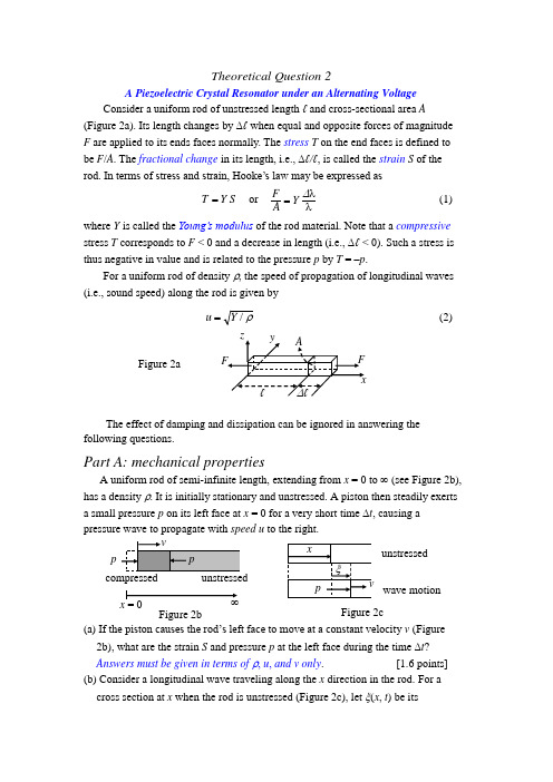
Theoretical Question 2A Piezoelectric Crystal Resonator under an Alternating VoltageConsider a uniform rod of unstressed length ℓ and cross-sectional area A(Figure 2a). Its length changes by ∆ℓ when equal and opposite forces of magnitude F are applied to its ends faces normally. The stress T on the end faces is defined to be F /A . The fractional change in its length, i.e., ∆ℓ/ℓ, is called the strain S of the rod. In terms of stress and strain, Hooke’s law may be expressed asS Y T = or∆Y A F = (1) where Y is called the Young’s modulus of the rod material. Note that a compressive stress T corresponds to F < 0 and a decrease in length (i.e., ∆ℓ < 0). Such a stress is thus negative in value and is related to the pressure p by T = –p .For a uniform rod of density ρ, the speed of propagation of longitudinal waves (i.e., sound speed) along the rod is given byρ/Y u = (2)The effect of damping and dissipation can be ignored in answering the following questions.Part A: mechanical propertiesA uniform rod of semi-infinite length, extending from x = 0 to ∞ (see Figure 2b), has a density ρ. It is initially stationary and unstressed. A piston then steadily exerts a small pressure p on its left face at x = 0 for a very short time ∆t , causing a pressure wave to propagate with speed u to the right.(a) If the piston causes the rod’s left face to move at a constant velocity v (Figure 2b), what are the strain S and pressure p at the left face during the time ∆t ?Answers must be given in terms of ρ, u , and v only . [1.6 points] (b) Consider a longitudinal wave traveling along the x direction in the rod. For a cross section at x when the rod is unstressed (Figure 2c), let ξ(x , t ) be itsFigure 2aFigure 2cFigure 2bdisplacement at time t and assume)(sin ),(0t u x k t x -=ξξ (3)where ξ0 and k are constants. Determine the corresponding velocity v (x , t ), strain S (x , t ), and pressure p (x , t ) as a function of x and t . [2.4 points] Part B: electromechanical properties (including piezoelectriceffect)Consider a quartz crystal slab of length b , thickness h , and width w (Figure 2d). Its length and thickness are along the x-axis and z-axis. Electrodes are formed by thin metallic coatings at its top and bottom surfaces. Electrical leads that also serve as mounting support (Figure 2e) are soldered to the electrode’s centers, which may be assumed to be stationary for longitudinal oscillations along the x direction.The quartz crystal under consideration has a density ρ of 2.65⨯103 kg/m 3 and Young’s modulus Y of 7.87⨯1010 N/m 2. The length b of the slab is 1.00 cm and the width w and heighth of the slab are such that h << w and w << b . With switch K left open, we assume only longitudinal modes of standing wave oscillation in the x direction are excited in the quartz slab.For a standing wave of frequency f =ω/2π, the displacement ξ(x , t ) at time t of a cross section of the slab with equilibrium position x may be written ast x g t x ωξξcos )(2),(0=, )0(b x ≤≤ (4a)where ξ0 is a positive constant and the spatial function g (x ) is o f t h e f o rm ).2(cos )2(sin )(21b x k B b x k B x g -+-= (4b) g(x) has the maximum value of one and k=ω/u . Keep in mind that the centers of the electrodes are stationary and the left and right faces of the slab are free and must have zero stress (or pressure).(c) Determine the values of B 1 and B 2 in Eq. (4b) for a longitudinal standing wave in the quartz slab. [1.2 point] (d) What are the two lowest frequencies at which longitudinal standing waves may be excited in the quartz slab? [1.2 point]The piezoelectric effect is a special property of a quartz crystal. Compression or dilatation of the crystal generates an electric voltage across the crystal, andconversely, an external voltage applied across the crystal causes the crystal to expand or contract depending on the polarity of the voltage. Therefore, mechanical andelectrical oscillations can be coupled and made to resonate through a quartz crystal.To account for the piezoelectric effect, let the surface charge densities on the upper and lower electrodes be –σ and +σ, respectively, when the quartz slab is under an electric field E in the z direction. Denote the slab’s strain and stress in the xdirection by S and T , respectively. Then the piezoelectric effect of the quartz crystal can be described by the following set of equations:E d T Y S p +=)/1( (5a)E T d T p εσ+= (5b)where 1/Y = 1.27⨯10−11 m 2/N is the elastic compliance (i.e., inverse of Young’s modulus) at constant electric field and εT = 4.06⨯10−11 F/m is the permittivity at constant stress, while d p = 2.25⨯10−12 m/V is the piezoelectric coefficient .Let switch K in Fig. 2d be closed. The alternating voltage V (t ) = V m cos ωt now acts across the electrodes and a uniform electric field E (t ) = V (t )/h in the z direction appears in the quartz slab. When a steady state is reached, a longitudinal standing wave oscillation of angular frequency ω appears in the slab in the x direction.With E being uniform, the wavelength λ and the frequency f of a longitudinal standing wave in the slab are still related by λ = u /f with u given by Eq. (2). But, as Eq. (5a) shows, T = Y S is no longer valid, although the definitions of strain and stress remain unchanged and the end faces of the slab remain free with zero stress. (e) Taking Eqs. (5a) and (5b) into account, the surface charge density σ on the lower electrode as a function of x and t is of the form,,)(2cos ),(21h t V D b x k D t x ⎥⎦⎤⎢⎣⎡+⎪⎭⎫ ⎝⎛-=σ where k =ω/u . Find the expressions for D 1 and D 2. [2.2 points] (f) The total surface charge Q (t ) on the lower electrode is related to V (t ) by)()]12tan 2(1[)(02t V C kb kb t Q -+=α (6) Find the expression for C 0 and the expression and numerical value of α2.[1.4 points][Answer Sheet] Theoretical Question 2A Piezoelectric Crystal Resonator under an Alternating VoltageWherever requested, give each answer as analytical expressions followed by numerical values and units. For example:area of a circle A = πr2 = 1.23 m2.(b) The velocity v(x, t), strain S(x, t), and pressure p(x, t) are(e) The expressions of D and D are。

2014年第九届全国高中应用物理竞赛(立思杯)试题注意事项:1.请在密封线内填写所在地区、学校、姓名和考号。
2.用蓝色或黑色钢笔、圆珠笔书写。
3.答卷过程中可以使用普通型计算器。
4.本试卷共有三个大题,总分为150分。
5.答卷时间:2014年4月13日(星期日)上午9:30~11:30。
一、本题包括11小题,考生只需做10小题,每小题5分,共50分。
在每小题给出的四个选项中,有的小题只有一个选项正确,有的小题有多个选项正确。
请把符合题目要求的选项的序号填入题后的( )内。
全选对的得5分,选不全的得3分,有选错或不选的得0分。
1.某电子仪器中为了便于调节电路中的电流,在它的调节部分常将两个滑动变阻器串联使用,如图1所示。
已知这两个滑动变阻器分别用不同的电阻丝绕在相同的绝缘瓷管上制成的,并且滑片在变阻器上调节过程中可移动的最大距离相等,其中R1的总电阻是200 Ω,R2的总电阻是5000Ω。
开始时两变阻器接入电路的阻值最大。
下面的几种方法中,能够既快又准确地使电流表指针指到要求位置的是( )A.先调节R1,使电流表指针指到要求位置附近,再调节R2B.先调节R2,使电流表指针指到要求位置附近,再调节R1C.同时调节R1和R2,使电流表指针指到要求位置D.交替、反复调节R1和R2,使电流表指针指到要求位置2.在喜庆的夜晚,人们有时要燃放焰火来增加欢乐的气氛。
当礼花弹凌空在最高点炸开后,通常我们会看在空中先形成一个五彩缤纷的“火球”并迅速“膨胀”,而后“火球”散落下来(如图2)。
在一个无风的夜晚放焰火,对于这些“火球”在空中散落下来过程中的形状,若不考虑空气阻力的作用,则图3中所给出的情景可能正确的是( )图2 图33.在一些高电压、强电流的环境下,普通的交流电流表不能直接用来测量电路中的电流,通常要通过电流互感器来连接。
图4甲为某型号的电流互感器,其中a、b两接线柱分别与其内部的一组线圈的两端相连接:c、d两接线柱分别与其内部的另一细线圈的两端相连接。
Problems of the XI International Olympiad, Moscow, 1979The publication has been prepared by Prof. S. Kozel and Prof. V.Orlov(Moscow Institute of Physics and Technology)The XI International Olympiad in Physics for students took place in Moscow, USSR, in July 1979 on the basis of Moscow Institute of Physics and Technology (MIPT). Teams from 11 countries participated in the competition, namely Bulgaria, Finland, Germany, Hungary, Poland, Romania, Sweden, Czechoslovakia, the DDR, the SFR Yugoslavia, the USSR. The problems for the theoretical competition have been prepared by professors of MIPT (V.Belonuchkin, I.Slobodetsky, S.Kozel). The problem for the experimental competition has been worked out by O.Kabardin from the Academy of Pedagogical Sciences.It is pity that marking schemes were not preserved.Theoretical ProblemsProblem 1.A space rocket with mass M=12t is moving around the Moon along the circular orbit at the height of h=100 km. The engine is activated for a short time to pass at the lunar landing orbit. The velocity of the ejected gases u = 104 m/s. The Moon radius R M = 1,7·103 km, the acceleration of gravity near the Moon surface g M = 1.7 m/s2Fig.1 Fig.21). What amount of fuel should be spent so that when activating the braking engine atpoint A of the trajectory, the rocket would land on the Moon at point B (Fig.1)?2). In the second scenario of landing, at point A the rocket is given an impulse directedtowards the center of the Moon, to put the rocket to the orbit meeting the Moon surfaceat point C (Fig.2). What amount of fuel is needed in this case?Problem 2.Brass weights are used to weigh an aluminum-made sample on an analytical balance. The weighing is ones in dry air and another time in humid air with the water vapor pressure P h =2·103 Pa. The total atmospheric pressure (P = 105 Pa) and the temperature (t =20° C) are the same in both cases.What should the mass of the sample be to be able to tell the difference in the balancereadings provided their sensitivity is m0= 0.1 mg ?Aluminum density ρ1= 2700 kg/m3, brass density ρ2=.8500 kg/m3.Problem 3.During the Soviet-French experiment on the optical location of the Moon the light pulse of a ruby laser (λ= 0,69 μm) was directed to the Moon’s surface by the telescope with a diameter of the mirror D= 2,6 m. The reflector on the Moon’s surface reflected the light backward as an ideal mirror with the diameter d = 20 cm. The reflected light was then collected by the same telescope and focused at the photodetector.1)What must the accuracy to direct the telescope optical axis be in this experiment?2)What part of emitted laser energy can be detected after reflection on the Moon, if weneglect the light loses in the Earth’s atmosph ere?3)Can we see a reflected light pulse with naked eye if the energy of single laser pulseE = 1 J and the threshold sensitivity of eye is equal n =100 light quantum?4)Suppose the Moon’s surface reflects α = 10% of the incident light in the spatial an gle 2πsteradian, estimate the advantage of a using reflector.The distance from the Earth to the Moon is L = 380000 km. The diameter of pupil of the eye isd p = 5mm. Plank constant is h = 6.6ּ10-34 Jּs.Experimental ProblemDefine the electrical cir cuit scheme in a “black box” and determine the parameters of its elements. List of instruments: A DC source with tension 4.5 V, an AC source with 50 Hz frequency and output voltage up to 30 V, two multimeters for measuring AC/DC current and voltage, variable resistor, connection wires.Solution of Problems of the XI International Olympiad, Moscow, 1979Solution of Theoretical ProblemsProblem 1.1) During the rocket moving along the circular orbit its centripetal acceleration is created by moon gravity force:R Mv RMM G M 202=, where R = R M + h is the primary orbit radius, v 0 -the rocket velocity on the circular orbit:RM Gv M=0 Since 2MMM R M Gg = it yields hR g R RR g v M MMMM +==20 (1)The rocket velocity will remain perpendicular to the radius-vector OA after the braking engine sends tangential momentum to the rocket (Fig.1). The rocket should then move along the elliptical trajectory with the focus in the Moon’s center.Denoting the rocket velocity at points A and B as v A and v B we can write the equations for energy and momentum conservation as follows:MMB M A R MM GMv R MM G Mv -=-2222 (2) Mv A R = Mv B R M(3)Solving equations (2) and (3) jointly we find)(2M MM A R R R R M Gv +=Taking (1) into account, we getMMA R R R v v +=20.Thus the rocket veloci ty change Δv at point A must be./2422121000s m h R R v R R R v v v v M M MMA =⎪⎪⎭⎫ ⎝⎛+-=⎪⎪⎭⎫ ⎝⎛+-=-=∆ Since the engine switches on for a short time the momentum conservation low in the system“rocket -fuel” can be written in the form (M – m 1)Δv = m 1uwhere m 1 is the burnt fuel mass. This yieldsvu vm ∆+∆=1 Allow for Δv << u we findkg 291=∆≈M uvm2) In the second case the vectoris directed perpendicular to the vectorthus givingBased on the energy conservation law in this case the equation can be written as()MMC M R GMM Mv R GMM v v M -=-∆+2222220 (4)and from the momentum conservation lawM C R Mv R Mv =0.(5)Solving equations (4) and (5) jointly and taking into account (1) we find()m/s 9722≈+=-=∆hR g hRR R g v M MM M.Using the momentum conservation law we obtainkg 11622≈∆=M uv m .Problem 2.A sample and weights are affected by the Archimede’s buoyancy force of either dry or humid air in the first and second cases, respectively. The difference in the scal e indication ΔF is determined by the change of difference of these forces.The difference of Archimede’s buoyancy forces in dry air: g V F a '1ρ∆=∆Whereas in humid air it is:where ΔV - the difference in volumes between the sample and the weights, and "a 'and ρρa - densities of dry and humid air, respectively.Then the difference in the scale indications ΔF could be written as follows:()"'21aa Vg F F F ρρ-∆=∆-∆=∆ (1)According to the problem conditions this difference should be distinguished, i.e.g m F 0≥∆ or ()0"'m Vg a a ≥-∆ρρ , wherefrom"'0aa mV ρρ-≥∆ .(2) The difference in volumes between the aluminum sample and brass weights can be found from the equation⎪⎪⎭⎫ ⎝⎛-=-=∆211221ρρρρρρm mm V , (3)where m is the sought mass of the sample. From expressions (2) and (3) we obtain⎪⎪⎭⎫⎝⎛--≥⎪⎪⎭⎫ ⎝⎛-∆=1221"'01221ρρρρρρρρρρa a m V m . (4)To find the mass m of the sample one has to determine the difference ()"'aa ρρ- . With the general pressure being equal, in the second case, some part of dry air is replaced by vapor:Vm V m v a a a ∆-∆=-"'ρρ .Changes of mass of air Δm a and vapor Δm v can be found from the ideal-gas equation of stateRT VM P m a a a =∆ , RTVM P m vv v =∆,wherefrom we obtain()RTM M P v a a a a -=-"'ρρ . (5)From equations (4) and (5) we obtain()⎪⎪⎭⎫ ⎝⎛--≥12210ρρρρv a a M M P RTm m . (6) g V F a "2ρ∆=∆The substitution of numerical values gives the answer: m ≥ 0.0432 kg ≈ 43 g.Note. When we wrote down expression (3), we considered the sample mass be equal to the weights’ mass, at the same time allowing for a small error.One may choose another way of solving this problem. Let us calculate the change of Archimede’s force by the c hange of the air average molar mass.In dry air the condition of the balance between the sample and weights could be written down in the form of2211V RT P M V RT P M a a ⎪⎭⎫ ⎝⎛-=⎪⎭⎫ ⎝⎛-ρρ .(7) In humid air its molar mass is equal to,PP P M P P M M av a a -+= (8)whereas the condition of finding the scale error could be written in the form02211m V RT P M V RT P M a a ≥⎪⎭⎫ ⎝⎛--⎪⎭⎫ ⎝⎛-ρρ.(9) From expressions (7) –(9) one can get a more precise answer()()av a aa P M M P M RT m m 12210ρρρρ---≥. (10)Since a a P M <<RT m 210ρρ , then both expressions (6) and (10) lead practically to the same quantitative result , i.e. m ≥ 43 g.Problem 3.1) The beam divergence angle δφ caused by diffraction defines the accuracy of the telescope optical axis installation:δφ ≈ λ/D ≈ 2.6∙10-7 rad. ≈ 0.05″ .2) The part K 1 of the light energy of a laser, directed to a reflector, may be found by the ratio of the area of S 1 reflector ( S 1 = πd 2/4 ) versus the area S 2 of the light spot on the Moon (S 2 = πr 2 , where r = L δφ ≈ Lλ/D, L – the distance from the Earth to the Moon)()22222221142LD d r d S S K λ===The reflected light beam diverges as well and forms a light spot with the radius R on the Earth’s surface:R = λL/d, as r << RThat’s why the part K 2 of the reflected energy, which got into the telescope, makes()222222242Ld D R D K λ== The part K 0 of the laser energy, that got into the telescope after having been reflected by the reflector on the Moon, equals42102⎪⎭⎫ ⎝⎛==L dD K K K λ≈ 10-123) The pupil of a naked eye receives as less a part of the light flux compared to a telescope, as the area of the pupil S e is less than the area of the telescope mirror S t :≈==2200Dd K S S K Ke t e e 3.7∙10-18 .So the number of photons N getting into the pupil of the eye is equale K h E N ν== 12.Since N<n, one can not perceive the reflected pulse with a naked eye.4) In the absence of a reflector α =10% of the laser energy, that got onto the Moon, are dispersed by the lunar surface within a solid angle Ω1 = 2π steradian.The solid angle in which one can see the telescope mirror from the Moon, constitutesΩ2 = S t /L 2 = πD 2/4L 2That is why the part K of the energy gets into the telescope and it is equalThus, the gain β , which is obtained through the use of the reflector is equalβ = K 0/K ≈ 2·106Note. The result obtained is only evaluative as the light flux is unevenly distributed inside the angle of diffraction.182212105.08-⋅≈=ΩΩ=L D K ααSolution of Experimental Problem.A transformer is built-in in a “black box”. The black box has 4 terminals. To be able to determine the equivalent circuit and the parameters of its elements one may first carry out measurements of the direct current. The most expedient is to mount the circuit according to the layout in Fig.3 and to build volt-ampere characteristics for various terminals of the “box”. This enables one to mak e sure rightway that there were no e.m.f. sources in the “box” (the plot I=f(U) goes through the origin of the coordinates), no diodes (the current strength does not depend on the polarity of the current’s external source), by the inclination angle of th e plot one may define the resistances between different terminals of the “box”. The tests allowed for some estimations of values R 1-2 and R 3-4. The ammeter did not register any current between the other terminals. This means that between these terminals there might be some other resistors with resistances larger than R L :ohm 1025.2A102V5,466min max ⋅=⋅==-I U R L where I min - the minimum value of the strength of the current which the instrument would haveregistered. Probably there might be some capacitors between terminals 1-3, 1-4, 2-3, 2-4 (Fig.4).Then, one can carry out analogous measurements of an alternative current. The taken volt-ampere characteristics enabled one to find full resistances on the alternative current of sections 1-2 and 3-4: Z 1 and Z 2 and to compare them to the values R 1 and R 2. It turned out, that Z 1>R 2 and Z 2>R 2.Fig.4Fig.5This fact allows one to conclude that in the “black box” the coils are connected to terminals 1-2 and 3-4 (Fig.5). Inductances of coils L 1 and L 2 can be determined by the formulasFig.3“Black box”πν221211R Z L -=, πν222222R Z L -=.After that the dependences Z = f(I), L=f(I) are to be investigated. The character of the found dependences enabled one to draw a conclusion about the presence of ferromagnetic cores in the coils. Judging by the results of the measurements on the alternative current one could identify the upper limit of capacitance of the capacitors which could be placed between terminals 1-3, 1-4, 2-3, 2-4:69min max1max 510A 510F 5nF 223.1450s 3VI C U πν---⋅===⋅=⋅⋅⋅ Th-2 and 3-4. The plotof dependence of voltage U 3-4 versus voltage U 1-2 (Fig. 6) allows one to find both the transformation coefficient214321==--U U K and the maximum operational voltages on coils L 1 and L 2, when the transformationFig.6coefficient has not changed yet, i.e. before saturation of the core. U 1-2(max) =2.5 V, U 3-4(max) = 5 V.One could build either plot K (U 1-2) or K (U 3-4) (Fig. 7).Fig.7Note: It was also possible to define the “box” circuit after tests of the direct current. To do that one had to find the presence of induction coupling between terminals 1-2 and 3-4, that is the appearance of e.m.f. of induction in circuit 3-4, when closing and breaking circuits 1-2 and vice-versa. When comparing the direction of the pointer’s rejection of the voltmeters connected to terminals 1-2 and 3-4 one could identify directions of the transformer’s windings.AcknowledgementThe authors would like to express their thanks and gratitude to Professor Waldemar Gorzkowski and Professor Ivo Volf for supplying the materials for the XI IphO in the Polish, Hungarian and Czech languages that have been of great help to the authors in their work at the problems of the Olympiad.References:1.O.Kabardin, V.Orlov, International Physics Olympiads for Pupuls, Nauka, Moskva 1985.2.W.Gorzkowski, A.Kotlicki, Olimpiady Fizyczne XXVII i XXVIII, WsiP, Warszawa 19833.R.Kunfalvi, Collection of Competition Tasks from the 1 trough XV International PhysicsOlympiads, 1867-1984, Roland Eotvos Physical Society an UNESCO, Budapest 19854.V.Urumov, Megjunadodni Olimpijadi po Fisika, Prosvento Delo, Skopje 19995. D.Kluvanec, I.Volf, Mezinarodni Fysikalni Olympiady, MaFy, Hradec Kralowe 1993。
2014年高中物理竞赛高 二 试卷注意事项:1.本试卷共23题,满分为150分,考试时间120分钟. 2.将每题的答案答题卷上,在试卷上答题无效,本卷g 取10m/s 2.一、选择题(本题共10 小题,每小题 4 分,共40 分.每小题只有一个选项符合题意). 1.如图所示,棒AB 上均匀分布着正电荷,它的中点正上方有一P 点,则P 点的场强方向为(A )垂直于AB 向上 (B )垂直于AB 向下 (C )平行于AB 向左 (D )平行于AB 向右2.在物理学发展的过程中,有许多伟大的科学家做出了贡献。
关于科学家和他们的贡献,下列说法正确的是(A )安培首先提出了磁场对运动电荷的作用力公式(B )法拉第根据小磁针在通电导线周围的偏转而发现了电流的磁效应(C )法国物理学家库仑利用扭秤实验发现了电荷之间的相互作用规律——库仑定律 (D )楞次发现了电磁感应现象,并研究得出了判断感应电流方向的方法——楞次定律 3.两木块自左向右运动,现用高速摄影机在同一底片上多次曝光,记录下木块每次曝光时的位置,如下图所示,连续两次曝光的时间间隔是相等的,由图可知(A )在时刻t 2以及时刻t 5两木块速度相同 (B )在时刻t 1两木块速度相同(C )在时刻t 3和时刻t 4之间某瞬时两木块速度相同 (D )在时刻t 4和时刻t 5之间某瞬时两木块速度相同4.如图所示,水平放置的两块带电平行金属板.板间存在着方向竖直向下、场强大小为E 的匀强电场和垂直于纸面的匀强磁场.假设电场、磁场只存在于两板间.一个带正电的粒子,以水平速度v 0从两极板的左端正中央沿垂直于电场、磁场的方向射入极板间,恰好做匀速直线运动.不计粒子的重力及空气阻力.则 (A)板间所加的匀强磁场0EB v,方向垂直于纸面向里 (B)若粒子电量加倍,将会向下偏转(C)若粒子从极板的右侧射入,一定沿直线运动 (D)若粒子带负电,其它条件不变,将向上偏转 5.用两个相同的小量程电流表,分别改装成了两个量程不同的大量程电流表A 1、A 2,若把A 1、A 2分别采用串联或并联的方式接入电路,如图(a )、(b )所示,则闭合开关后,下列有关电表的示数和电表指针偏转角度的说法正确的是v 0E(A)图(a )中的A 1、A 2的示数相同 (B)图(a )中的A 1、A 2的指针偏角相同 (C)图(b )中的A 1、A 2的示数和偏角都不同 (D)图(b )中的A 1、A 2的指针偏角相同6.如图所示,半径为R 的半球形碗固定于水平地面上,一个质量为m 的物块,从碗口沿内壁由静止滑下,滑到最低点时速度大小为v ,物块与碗之间的动摩擦因数恒为μ,则下列说法正确的是(A )在最低点时物块所受支持力大小为mg(B )整个下滑过程物块所受重力的功率一直增大(C )物块在下滑至最低点过程中动能先增大后减小 (D )整个下滑过程摩擦力对滑块做功212mgR mv -7.如图所示电路,电源内阻不能忽略,R 的阻值小于变阻器的总电阻,开始时滑动变阻器的滑片P 停在变阻器的中点,稳定后滑片P 由中点向上移动至顶端的全过程中(A )电压表的示数先减小后增大 (B )电压表的示数先增大后减小 (C )电流表的示数先增大后减小 (D )电流表的示数先减小后增大8.如图所示,导线AB 可在置于匀强磁场中的不计电阻的金属框架上滑动,则下列判断正确的是 (A)AB 向左匀加速运动时,电流表中电流均匀增大 (B)AB 向左减速运动时,电流表中有电流方向由a→b (C)AB 向右加速运动时,电流表中有电流方向由b→a (D )AB 向左匀速运动时,电流表中有电流方向由a →b9.如图所示,一足够长的木板在光滑的水平面上以速度v 匀速运动,现将质量为m 的物体竖直向下无初速轻轻地放置在木板上的P 处,已知物体m 和木板之间的动摩擦因数为μ。
V International Physics Olympiad, 1971Sofia, BulgariaThe problems and the solutions are adapted byVictor IvanovUniversity of Sofia, Faculty of Physics, 5 James Bourchier Blvd., 1164 Sofia, Bulgaria Reference: O. F. Kabardin, V. A. Orlov, in “Internat ional Physics Olympiads for High School Students”, eds. V. G. Razumovski, Moscow, Nauka, 1985. (In Russian).Theoretical problemsQuestion 1.A triangular prism of mass M is placed one side on a frictionless horizontal plane as shown in Fig. 1. The other two sides are inclined with respect to the plane at angles α1 and α2 respectively. Two blocks of masses m1 and m2, connected by an inextensible thread, can slide without friction on the surface of the prism. The mass of the pulley, which supports the thread, is negligible.∙Express the acceleration a of the blocks relative to the prism in terms of the acceleration a0 of the prism.∙Find the acceleration a0 of the prism in terms of quantities given and the acceleration g due to gravity.∙At what ratio m1/m2 the prism will be in equilibrium?Fig. 1Question 2.A vertical glass tube of cross section S= 1.0 cm2contains unknown amount of hydrogen. The upper end of the tube is closed. The other end is opened and is immersed in a pan filled with mercury. The tube and the pan are placed in a sealed chamber containing air at temperature T0 = 273 K and pressure P0 = 1.334⨯105 Pa. Under these conditions the height of mercury column in the tube above the mercury level in the pan is h0 = 0.70 m.One of the walls of the chamber is a piston, which expands the air isothermally to a pressure of P1= 8.00⨯104Pa. As a result the height of the mercury column in the tube decreases to h1= 0.40 m. Then the chamber is heated up at a constant volume to some temperature T2 until the mercury column rises to h2 = 0.50 m. Finally, the air in the chamber is expanded at constant pressure and the mercury level in the tube settles at h3 = 0.45 m above the mercury level in the pan.Provided that the system is in mechanical and thermal equilibrium during all the processes calculate the mass m of the hydrogen, the intermediate temperature T 2, and the pressure P in the final state.The density of mercury at temperature T 0 is ρ0 = 1.36⨯104 kg/m 3, the coefficient of expansion for mercury β = 1.84⨯10–4 K –1, and the gas constant R = 8.314 J/(mol ⨯K). The thermal expansion of the glass tube and the variations of the mercury level in the pan are not considered.Hint . If ∆T is the interval of temperature variations of the system then β∆T = x << 1 In that case you can use the approximation: x x-≈+111. Question 3.Four batteries of EMF E 1 = 4 V, E 2 = 8 V, E 3 = 12 V, and E 4 = 16 V, four capacitors with the same capacitance C 1 = C 2 = C 3 = C 4 = 1 μF, and four equivalent resistors are connected in the circuit shown in Fig. 3. The internal resistance of the batteries is negligible.∙ Calculate the total energy W accumulated on the capacitors when a steady state of thesystem is established.∙ The points H and B are short connected. Find the charge on the capacitor C 2 in thenew steady state.Fig. 3Question 4.A spherical aquarium, filled with water, is placed in front of a flat vertical mirror. The radius of the aquarium is R , and the distance between its center and the mirror is 3R . A small fish, which is initially at the point nearest to the mirror, starts to move with velocity v along the wall. An observer looks at the fish from a very large distance along a horizontal line passing trough the center of the aquarium.What is the relative velocity v rel at which the two images of the fish seen by the observer will move apart? Express your answer in terms of v . Assume that:∙ The wall of the aquarium is made of a very thin glass.∙ The index of refraction of water is n = 4/3.C 2 C 4Experimental ProblemApparatus: dc source, ammeter, voltmeter, rheostat (coil of high resistance wire with sliding contact), and connecting wires.Problem: Construct appropriate circuit and establish the dependence of the electric power P dissipated in the rheostat as a function of the current I supplied by the dc source.1.Make a plot of P versus I.2.Find the internal resistance of the dc source.3.Determine the electromotive force E of the source.4.Make a graph of the electric power P versus resistance R of the rheostat.5.Make a graph of the total power P tot dissipated in the circuit as a function of R.6.Make a graph of the efficiency of the dc source versus R.。