Linux下SPI驱动测试程序
- 格式:doc
- 大小:41.00 KB
- 文档页数:9

linuxSPI驱动——gpio模拟spi驱动(转载)⼀:⾸先在我的平台注册platform_device,保证能让spi-gpio.c能执⾏到probe函数。
1: struct spi_gpio_platform_data {2: unsigned sck;3: unsigned mosi;4: unsigned miso;5:6: u16 num_chipselect;7: };1: //#define NCS GPIO_PB(2) //定义SS所对应的GPIO接⼝编号2: //#define SCLK GPIO_PB(0) //定义SCLK所对应的GPIO接⼝编号3: //#define MOSI GPIO_PB(4) //定义SCLK所对应的GPIO接⼝编号4: //#define MISO GPIO_PB(1)5: static struct spi_gpio_platform_data jz_spi_gpio_data = {6: .sck = GPIO_PB(0), //GPIO_SPI_SCK,7: .mosi = GPIO_PB(4), //GPIO_SPI_MOSI,8: .miso = GPIO_PB(1), //GPIO_SPI_MISO,9: .num_chipselect = 1,10: };11:12: struct platform_device jz_spi_gpio_device = {13: .name = "spi_gpio",14: .id = 0,15: .dev = {16: .platform_data = &jz_spi_gpio_data,17: },18: };注册platform device1: platform_device_register(&jz_spi_gpio_device);⼆:注册platform_driver在spi_gpio.c⾥⾯注册platform driver1: MODULE_ALIAS("platform:" DRIVER_NAME);2:3: static struct platform_driver spi_gpio_driver = {4: = DRIVER_NAME,5: .driver.owner = THIS_MODULE,6: .remove = __exit_p(spi_gpio_remove),7: };8:9: static int __init spi_gpio_init(void)10: {11: return platform_driver_probe(&spi_gpio_driver, spi_gpio_probe);12: }13: module_init(spi_gpio_init);14:15: static void __exit spi_gpio_exit(void)16: {17: platform_driver_unregister(&spi_gpio_driver);18: }19: module_exit(spi_gpio_exit);20:21:22: MODULE_DESCRIPTION("SPI master driver using generic bitbanged GPIO ");23: MODULE_AUTHOR("David Brownell");24: MODULE_LICENSE("GPL");三:具体算法分析1: struct spi_gpio {2: struct spi_bitbang bitbang; /* gpio 模拟spi算法相关的结构 */3: struct spi_gpio_platform_data pdata; /* spi platform data 对应模拟spi的四个gpio编号 */4: struct platform_device *pdev; /* 对应注册的 platform device */5: };1:2: static int __init spi_gpio_probe(struct platform_device *pdev)3: {4: int status;5: struct spi_master *master;6: struct spi_gpio *spi_gpio;7: struct spi_gpio_platform_data *pdata;8: u16 master_flags = 0;9:10: pdata = pdev->dev.platform_data; /* 存放spi的四根gpio */11: #ifdef GENERIC_BITBANG12: if (!pdata || !pdata->num_chipselect)13: return -ENODEV;14: #endif15:16: /* 申请注册四个gpio */17: status = spi_gpio_request(pdata, dev_name(&pdev->dev), &master_flags);18: if (status < 0) {19: return status;20: }21:22: /* alloc a spi master ,master->dev->p->driver_data = &master[1]*/23: master = spi_alloc_master(&pdev->dev, sizeof *spi_gpio);24: if (!master) {25: status = -ENOMEM;26: goto gpio_free;27: }28: /* spi_gpio指向⼀块空间, 即指向mstaer[1]29: pdev->dev->p->driver_data = spi_gpio;30: 初始化spi_gpio31: */32: spi_gpio = spi_master_get_devdata(master);33: platform_set_drvdata(pdev, spi_gpio);34:35: spi_gpio->pdev = pdev;36: if (pdata)37: spi_gpio->pdata = *pdata;38:39: master->flags = master_flags;40: master->bus_num = pdev->id;41: master->num_chipselect = SPI_N_CHIPSEL;42: master->setup = spi_gpio_setup; /* setup ⽐如cs引脚申请 */43: master->cleanup = spi_gpio_cleanup;44: /* spi_gpio->bitbang.master = master */45: spi_gpio->bitbang.master = spi_master_get(master);46: spi_gpio->bitbang.chipselect = spi_gpio_chipselect;47: /* spi_gpio->bitbang.txrx_word 数组函数四个元素指针,分别指向spi四种mode算法函数 */ 48: if ((master_flags & (SPI_MASTER_NO_TX | SPI_MASTER_NO_RX)) == 0) {49: spi_gpio->bitbang.txrx_word[SPI_MODE_0] = spi_gpio_txrx_word_mode0;50: spi_gpio->bitbang.txrx_word[SPI_MODE_1] = spi_gpio_txrx_word_mode1;51: spi_gpio->bitbang.txrx_word[SPI_MODE_2] = spi_gpio_txrx_word_mode2;52: spi_gpio->bitbang.txrx_word[SPI_MODE_3] = spi_gpio_txrx_word_mode3;53: } else {54: spi_gpio->bitbang.txrx_word[SPI_MODE_0] = spi_gpio_spec_txrx_word_mode0;55: spi_gpio->bitbang.txrx_word[SPI_MODE_1] = spi_gpio_spec_txrx_word_mode1;56: spi_gpio->bitbang.txrx_word[SPI_MODE_2] = spi_gpio_spec_txrx_word_mode2;57: spi_gpio->bitbang.txrx_word[SPI_MODE_3] = spi_gpio_spec_txrx_word_mode3;58: }59: /* spi_gpio->bitbang.setup_transfer初始化传输的bits_per_word和speed */60: spi_gpio->bitbang.setup_transfer = spi_bitbang_setup_transfer;61: spi_gpio->bitbang.flags = SPI_CS_HIGH;62: /* spi_gpio->bitbang相关算法接⼝初始化 */63: status = spi_bitbang_start(&spi_gpio->bitbang);64: if (status < 0) {65: spi_master_put(spi_gpio->bitbang.master);66: gpio_free:67: if (SPI_MISO_GPIO != SPI_GPIO_NO_MISO)68: gpio_free(SPI_MISO_GPIO);69: if (SPI_MOSI_GPIO != SPI_GPIO_NO_MOSI)70: gpio_free(SPI_MOSI_GPIO);71: gpio_free(SPI_SCK_GPIO);72: spi_master_put(master);73: }74:75: return status;76: }四:总之最终让spi_gpi0整个对象存放了整个gpio模拟spi的算法结构;⽽pdev->dev->p->driver_data = spi_gpio;platform device和 platform driver两者match结果是:root@CarRadio:/# ls /sys/bus/platform/devices/spi_gpio.0/ driver modalias power spi0.0 spi_master subsystem uevent root@CarRadio:/# ls /sys/bus/platform/devices/spi_gpio.0/driver/ spi_gpio.0 uevent。

一概念用户空间驱动就是指在用户空间实现的驱动程序。
可以认为它跟普通的用户程序没有什么两样,它使用用户进程空间和栈,下面来看看用户态驱动的优点和缺点优点:1 可以和整个C库链接2 驱动的问题不会导致整个系统挂起3 容易调试缺点:1 中断和DMA在用户态是无法使用的(现在在用户态其实也是可以使用中断和DMA但是比较麻烦,比如可以使用poll函数来等待基于GPIO的中断,同样也可以使用/dev/mem来使用DMA)2 响应时间慢, 因为需要上下文切换在客户和硬件之间传递信息或动作所以总的来说对于一个较为慢速的不需要实时交互的设备,可以使用用户态的驱动来实现。
二spi用户态驱动spi用户驱动主要是依赖于内核模块spidev,该模块实现了一个通用的spi驱动,在用户空间调用该通用驱动提供的接口,操作相应的spi设备,其实这就是spi用户态驱动。
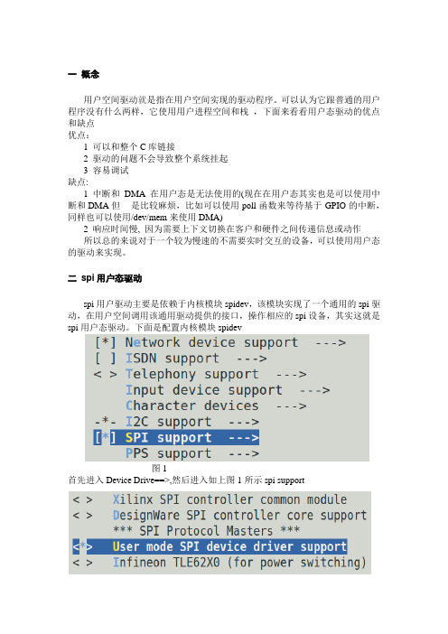
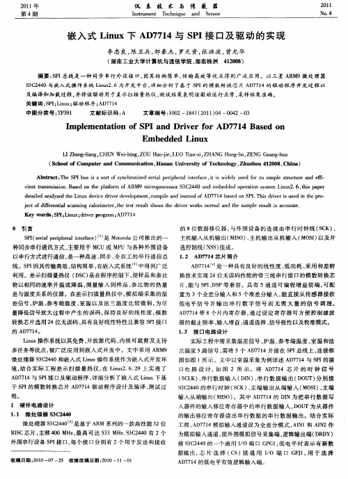
下面是配置内核模块spidev图1首先进入Device Drive==>,然后进入如上图1所示spi support图2如上图2选择用户态spi设备驱动,这样内核模块spidev就配置成功一添加spi_board_info首先需要在内核的arch/arm/mach-*/board-*.c 即BSP信息中添加一个spi_board_info(无论是用户态spi驱动还是内核态spi驱动都需要这样),同时名字必须是“spidev”,那么为什么要这么做了,这就是从 2.6内核起linux 驱动使用了一个叫做Device Model即设备模型的东东,总线,驱动和设备,总线将设备和驱动进行匹配,为了要能够使spi驱动的probe函数能够被调用,则必须存在一个设备与该驱动进行匹配,匹配成功后,spi子系统才会自动调用该驱动的probe函数,对于没有使用热插拔机制总线的设备比如platform,,spi,i2c,则必须手动在BSP信息中间手动添加设备信息,spi总线就是通过添加spi_board_info,来触发内核创建spi设备(struct spi_device),i2c则是添加i2c_board_info。
Linux驱动:SPI驱动编写要点题外话:⾯对成功和失败,⼀个⼈有没有“冠军之⼼”,直接影响他的表现。
⼏周前剖析了Linux SPI 驱动框架,算是明⽩个所以然,对于这么⼀个庞⼤的框架,并不是每⼀⾏代码都要⾃⼰去敲,因为前⼈已经把这个框架搭建好了,作为驱动开发者的我们只需要搞清楚哪⼀部分是需要⾃⼰修改或重新编写就OK了。
结合Linux内核⾯向对象的设计思想,SPI总的设计思路⼤概是这样的:第①处:内核中抽象了SPI控制器,让spi_master成为他的象征,他的实例化对象就是与硬⽣⽣的SPI控制器对应的,在Linux内核中习惯将集成到SOC上的控制器⽤假想的platform总线来进⾏管理,于是乎spi_master的实例化就得依靠platform_device和platform_driver来联⼿完成了。
细嚼慢咽:这⾥的platform_device就相当于是spi_master的静态描述:包括⼏号控制器、寄存器地址、引脚配置等等,把这些信息以“资源”的形式挂在platform_device上,等platform_driver找到命中注定的那个他之后就可以获得这个(静态描述)资源,probe中⽤这些资源就⽣出了spi_master实例对象。
这⼀系列流程前辈们都已经做好了,我们要做的就是将这静态描述platform_device修改成和⾃⼰SOC中的spi 控制器⼀致的特性即可。
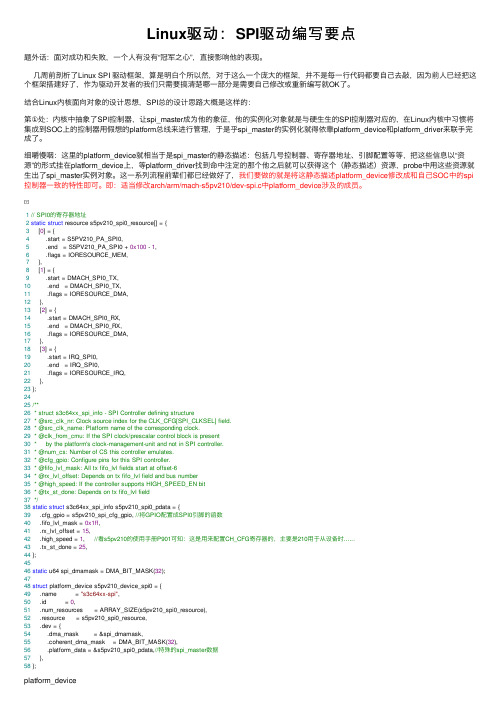
即:适当修改arch/arm/mach-s5pv210/dev-spi.c中platform_device涉及的成员。
1// SPI0的寄存器地址2static struct resource s5pv210_spi0_resource[] = {3 [0] = {4 .start = S5PV210_PA_SPI0,5 .end = S5PV210_PA_SPI0 + 0x100 - 1,6 .flags = IORESOURCE_MEM,7 },8 [1] = {9 .start = DMACH_SPI0_TX,10 .end = DMACH_SPI0_TX,11 .flags = IORESOURCE_DMA,12 },13 [2] = {14 .start = DMACH_SPI0_RX,15 .end = DMACH_SPI0_RX,16 .flags = IORESOURCE_DMA,17 },18 [3] = {19 .start = IRQ_SPI0,20 .end = IRQ_SPI0,21 .flags = IORESOURCE_IRQ,22 },23 };2425/**26 * struct s3c64xx_spi_info - SPI Controller defining structure27 * @src_clk_nr: Clock source index for the CLK_CFG[SPI_CLKSEL] field.28 * @src_clk_name: Platform name of the corresponding clock.29 * @clk_from_cmu: If the SPI clock/prescalar control block is present30 * by the platform's clock-management-unit and not in SPI controller.31 * @num_cs: Number of CS this controller emulates.32 * @cfg_gpio: Configure pins for this SPI controller.33 * @fifo_lvl_mask: All tx fifo_lvl fields start at offset-634 * @rx_lvl_offset: Depends on tx fifo_lvl field and bus number35 * @high_speed: If the controller supports HIGH_SPEED_EN bit36 * @tx_st_done: Depends on tx fifo_lvl field37*/38static struct s3c64xx_spi_info s5pv210_spi0_pdata = {39 .cfg_gpio = s5pv210_spi_cfg_gpio, //将GPIO配置成SPI0引脚的函数40 .fifo_lvl_mask = 0x1ff,41 .rx_lvl_offset = 15,42 .high_speed = 1, //看s5pv210的使⽤⼿册P901可知:这是⽤来配置CH_CFG寄存器的,主要是210⽤于从设备时......43 .tx_st_done = 25,44 };4546static u64 spi_dmamask = DMA_BIT_MASK(32);4748struct platform_device s5pv210_device_spi0 = {49 .name = "s3c64xx-spi",50 .id = 0,51 .num_resources = ARRAY_SIZE(s5pv210_spi0_resource),52 .resource = s5pv210_spi0_resource,53 .dev = {54 .dma_mask = &spi_dmamask,55 .coherent_dma_mask = DMA_BIT_MASK(32),56 .platform_data = &s5pv210_spi0_pdata,//特殊的spi_master数据57 },58 };platform_device第②处:添加/修改SPI外设“静态描述”的结构。

需要了解Linux下SPI从设备驱动的编写需要了解Linux下SPI从设备驱动的编写SPI(Serial Peripheral Interface) 是一个同步的四线制串行线,用于连接微控制器和传感器、存储器及外围设备。
三条信号线持有时钟信号(SCLK,经常在10MHz左右)和并行数据线带有“主出,从进(MOSI)”或是“主进,从出(MISO)”信号。
数据交换的时候有四种时钟模式,模式0和模式3是最经常使用的。
每个时钟周期将会传递数据进和出。
如果没有数据传递的话,时钟将不会循环。
SPI驱动分为两类:控制器驱动:它们通常内嵌于片上系统处理器,通常既支持主设备,又支持从设备。
这些驱动涉及硬件寄存器,可能使用DMA。
或它们使用GPIO引脚成为PIO bitbangers。
这部分通常会由特定的开发板提供商提供,不用自己写。
协议驱动:它们通过控制器驱动,以SPI连接的方式在主从设备之间传递信息。
这部分涉及具体的SPI从设备,通常需要自己编写。
那么特定的目标板如何让Linux 操控SPI设备?下面以AT91SAM9260系列CAN设备驱动为例,Linux内核版本为2.6.19。
本文不涉及控制器驱动分析。
board_info提供足够的信息使得系统正常工作而不需要芯片驱动加载[cpp] view plain copy在arch/arm/mach-at91rm9200/board-at91sam9260.c中有如下代码:#include#include…….static struct spi_board_info ek_spi_devices[] = {/* spi can ,add by mrz */#if defined(CONFIG_CAN_MCP2515) {.modalias = "mcp2515",.chip_select = 0,// .controller_data = AT91_PIN_PB3,。
linux下串口驱动测试程序2009-12-26 20:42:20| 分类:技术| 标签:|字号大中小订阅【转载时请注明文章出处:】为了测试串口驱动,我们需要用串口驱动测试程序先向串口写入数据,然后再从串口读出来,以证明串口驱动的正确性。
下面我们来分析一下串口驱动测试程序的流程。
1、串口程序需要的头文件#include <stdio.h> /*标准输入输出定义*/#include <stdlib.h> /*标准函数库定义*/#include <unistd.h> /*Unix 标准函数定义*/#include <sys/types.h>#include <sys/stat.h>#include <fcntl.h> /*文件控制定义*/#include <termios.h> /*PPSIX 终端控制定义*/#include <errno.h> /*错误号定义*/2、打开串口设备fd = open( "/dev/ttyS0", O_RDWR); 我们以/dev/ttyS0即一般机子上的COM1为例。
3、设置串口设备:串口设备的设置主要通过struct termio的结构体来完成:struct termio{ unsigned short c_iflag; /* 输入模式标志 */unsigned short c_oflag; /* 输出模式标志 */unsigned short c_cflag; /* 控制模式标志*/unsigned short c_lflag; /* 当前模式标志 */unsigned char c_line; /* line discipline */unsigned char c_cc[NCC]; /* 控制字 */};我们用下面函数实现具体的串口设置:int setup_port(int fd, int baud, int databits, int parity, int stopbits){struct termio term_attr;if (ioctl(fd, TCGETA, &term_attr) < 0) { //将fd所对应的终端信息存入termio结构,得到当前配置return -1;}memcpy(&oterm_attr, &term_attr, sizeof(struct termio)); //保持当前配置到oterm_attr,用于系统恢复term_attr.c_iflag &= ~(INLCR | IGNCR | ICRNL | ISTRIP);term_attr.c_oflag &= ~(OPOST | ONLCR | OCRNL);term_attr.c_lflag &= ~(ISIG | ECHO | ICANON | NOFLSH);term_attr.c_cflag &= ~CBAUD;term_attr.c_cflag |= CREAD | speed_to_flag(baud); //设置波特率//标志各种标志可选范围term_attr.c_cflag &= ~(CSIZE); //设置数据位长度switch (databits) {case 5:term_attr.c_cflag |= CS5; //设置数据位长度为5,下同break;case 6:term_attr.c_cflag |= CS6;break;case 7:term_attr.c_cflag |= CS7;break;case 8:default:term_attr.c_cflag |= CS8;break;}switch (parity) { //设置奇偶校验位case 1:term_attr.c_cflag |= (PARENB | PARODD); //奇校验break;case 2:term_attr.c_cflag |= PARENB; //偶校验term_attr.c_cflag &= ~(PARODD);break;case 0:default:term_attr.c_cflag &= ~(PARENB); //不校验break;}switch (stopbits) { //设置停止位case 2: //有停止位为两位,下同term_attr.c_cflag |= CSTOPB;break;case 1:default:term_attr.c_cflag &= ~CSTOPB;break;}term_attr.c_cc[VMIN] = 1; //更新设置,并且立即完成term_attr.c_cc[VTIME] = 0; //设置超时if (ioctl(fd, TCSETAW, &term_attr) < 0) { //将更改后的属性加载到设备中return -1;}if (ioctl(fd, TCFLSH, 2) < 0) { //将输入输出队列全部发出,清空串口中队列return -1;}return 0;}4、向串口写入数据:while ( (len = read(0, buf, MAX_BUF_SIZE)) > 0 ) { if (len == 1) { //如果当前缓冲区为空,则写入停止位,发送buf[0] = MY_END_CHAR;buf[1] = 0;write_data(fd, buf, len);break;}i = write_data(fd, buf, len); //发送缓冲区内容if (i == 0) {fprintf(stderr, "Send data error!\n");break;}}5、从串口读数据:len = MAX_BUF_SIZE;while (1) {i = read_data(fd, buf, len); //从串口读取数据if (i > 0) {//count += i;//fprintf(stderr, "Recv %d byte\n", i);printf("%s", buf);if (buf[i-1] == MY_END_CHAR) { //如果读入的倒数第二位为停止位,则中断接受程序break;}}}在具体的测试中,在PC机上gcc编译程序,然后用arm-linux-gcc编程程序发送到友善之臂2440的板子上,然后一边发送一边接受,这样如果发送的数据和接受的数据相同,则测试成功。
2.6.18内核下已经添加了完整的spi子系统了,参考mtd的分析,将从下到上层,再从上到下层的对其进行分析。
以下先从下到上的进行分析:driver/spi下有两个底层相关的spi驱动程序:spi_s3c24xx.c和spi_s3c24xx_gpio.c其中spi_s3c24xx.c是基于s3c24xx下相应的spi接口的驱动程序,spi_s3c24xx_gpio.c允许用户指定3个gpio口,分别充当spi_clk、spi_mosi和spi_miso接口,模拟标准的spi总线。
s3c2410自带了两个spi接口(spi0和spi1),在此我只研究基于s3c2410下spi接口的驱动程序spi_s3c24xx.c。
首先从spi驱动的检测函数进行分析:static int s3c24xx_spi_probe(struct platform_device *pdev){struct s3c24xx_spi *hw;struct spi_master *master;struct spi_board_info *bi;struct resource *res;int err = 0;int i;/* pi_alloc_master函数申请了struct spi_master+struct s3c24xx_spi大小的数据, * spi_master_get_devdata和pi_master_get分别取出struct s3c24xx_spi 和struct spi_master结构指针*/master = spi_alloc_master(&pdev->dev, sizeof(struct s3c24xx_spi));if (master == NULL) {dev_err(&pdev->dev, "No memory for spi_master\n");err = -ENOMEM;goto err_nomem;}/* 填充struct spi_master结构*/hw = spi_master_get_devdata(master);memset(hw, 0, sizeof(struct s3c24xx_spi));hw->master = spi_master_get(master);hw->pdata = pdev->dev.platform_data;hw->dev = &pdev->dev;if (hw->pdata == NULL) {dev_err(&pdev->dev, "No platform data supplied\n");err = -ENOENT;goto err_no_pdata;}platform_set_drvdata(pdev, hw);//dev_set_drvdata(&pdev->dev, hw)init_completion(&hw->done);/* setup the state for the bitbang driver *//* 填充hw->bitbang结构(hw->bitbang结构充当一个中间层,相当与inputsystem的input_handle struct) */hw->bitbang.master = hw->master;hw->bitbang.setup_transfer = s3c24xx_spi_setupxfer;hw->bitbang.chipselect = s3c24xx_spi_chipsel;hw->bitbang.txrx_bufs = s3c24xx_spi_txrx;hw->bitbang.master->setup = s3c24xx_spi_setup;dev_dbg(hw->dev, "bitbang at %p\n", &hw->bitbang);/* find and map our resources *//* 申请spi所用到的资源:io、irq、时钟等*/res = platform_get_resource(pdev, IORESOURCE_MEM, 0);if (res == NULL) {dev_err(&pdev->dev, "Cannot get IORESOURCE_MEM\n");err = -ENOENT;goto err_no_iores;}hw->ioarea = request_mem_region(res->start, (res->end - res->start)+1,pdev->name);if (hw->ioarea == NULL) {dev_err(&pdev->dev, "Cannot reserve region\n");err = -ENXIO;goto err_no_iores;}hw->regs = ioremap(res->start, (res->end - res->start)+1);if (hw->regs == NULL) {dev_err(&pdev->dev, "Cannot map IO\n");err = -ENXIO;goto err_no_iomap;}hw->irq = platform_get_irq(pdev, 0);if (hw->irq dev, "No IRQ specified\n");err = -ENOENT;goto err_no_irq;}err = request_irq(hw->irq, s3c24xx_spi_irq, 0, pdev->name, hw);if (err) {dev_err(&pdev->dev, "Cannot claim IRQ\n");goto err_no_irq;}hw->clk = clk_get(&pdev->dev, "spi");if (IS_ERR(hw->clk)) {dev_err(&pdev->dev, "No clock for device\n");err = PTR_ERR(hw->clk);goto err_no_clk;}/* for the moment, permanently enable the clock */clk_enable(hw->clk);/* program defaults into the registers *//* 初始化spi相关的寄存器*/writeb(0xff, hw->regs + S3C2410_SPPRE);writeb(SPPIN_DEFAULT, hw->regs + S3C2410_SPPIN);writeb(SPCON_DEFAULT, hw->regs + S3C2410_SPCON);/* add by lfc */s3c2410_gpio_setpin(S3C2410_GPE13, 0);s3c2410_gpio_setpin(S3C2410_GPE12, 0);s3c2410_gpio_cfgpin(S3C2410_GPE13, S3C2410_GPE13_SPICLK0);s3c2410_gpio_cfgpin(S3C2410_GPE12, S3C2410_GPE12_SPIMOSI0);s3c2410_gpio_cfgpin(S3C2410_GPE11, S3C2410_GPE11_SPIMISO0);/* end add *//* setup any gpio we can *//* 片选*/if (!hw->pdata->set_cs) {s3c2410_gpio_setpin(hw->pdata->pin_cs, 1);s3c2410_gpio_cfgpin(hw->pdata->pin_cs, S3C2410_GPIO_OUTPUT);}/* register our spi controller *//* 最终通过调用spi_register_master来注册spi控制器(驱动) */err = spi_bitbang_start(&hw->bitbang);if (err) {dev_err(&pdev->dev, "Failed to register SPI master\n");goto err_register;}dev_dbg(hw->dev, "shutdown=%d\n", hw->bitbang.shutdown);/* register all the devices associated *//* 注册所用使用本spi驱动的设备*/bi = &hw->pdata->board_info[0];for (i = 0; i pdata->board_size; i++, bi++) {dev_info(hw->dev, "registering %s\n", bi->modalias);bi->controller_data = hw;spi_new_device(master, bi);}return 0;err_register:clk_disable(hw->clk);clk_put(hw->clk);err_no_clk:free_irq(hw->irq, hw);err_no_irq:iounmap(hw->regs);err_no_iomap:release_resource(hw->ioarea);kfree(hw->ioarea);err_no_iores:err_no_pdata:spi_master_put(hw->master);;err_nomem:return err;}/** spi_alloc_master - allocate SPI master controller* @dev: the controller, possibly using the platform_bus* @size: how much driver-private data to preallocate; the pointer to this* memory is in the class_data field of the returned class_device,* accessible with spi_master_get_devdata().** This call is used only by SPI master controller drivers, which are the* only ones directly touching chip registers. It's how they allocate* an spi_master structure, prior to calling spi_register_master().** This must be called from context that can sleep. It returns the SPI* master structure on success, else NULL.** The caller is responsible for assigning the bus number and initializing* the master's methods before calling spi_register_master(); and (after errors* adding the device) calling spi_master_put() to prevent a memory leak.*//*注释已经写得很清楚了,本函数旨在分配spi_master struct *其中,device为主控制设备,size为需要预分配的设备私有数据大小*该函数被spi主控制器驱动所调用,用于在调用spi_register_master注册主控制器前*分配spi_master struct,分配bus number和初始化主控制器的操作方法*注意在分配spi_master struct的时候多分配了大小为size的设备私有数据*并通过spi_master_set_devdata函数把其放到class_data field里,以后可以通过spi_master_get_devdata来访问*/struct spi_master * __init_or_modulespi_alloc_master(struct device *dev, unsigned size){struct spi_master *master;if (!dev)return NULL;master = kzalloc(size + sizeof *master, SLAB_KERNEL);if (!master)return NULL;class_device_initialize(&master->cdev);master->cdev.class = &spi_master_class;master->cdev.dev = get_device(dev);spi_master_set_devdata(master, &master[1]);return master;}/** spi_bitbang_start - start up a polled/bitbanging SPI master driver* @bitbang: driver handle** Caller should have zero-initialized all parts of the structure, and then* provided callbacks for chip selection and I/O loops. If the master has* a transfer method, its final step should call spi_bitbang_transfer; or,* that's the default if the transfer routine is not initialized. It should* also set up the bus number and number of chipselects.** For i/o loops, provide callbacks either per-word (for bitbanging, or for* hardware that basically exposes a shift register) or per-spi_transfer* (which takes better advantage of hardware like fifos or DMA engines).** Drivers using per-word I/O loops should use (or call) spi_bitbang_setup and* spi_bitbang_cleanup to handle those spi master methods. Those methods are* the defaults if the bitbang->txrx_bufs routine isn't initialized.** This routine registers the spi_master, which will process requests in a* dedicated task, keeping IRQs unblocked most of the time. To stop* processing those requests, call spi_bitbang_stop().*/int spi_bitbang_start(struct spi_bitbang *bitbang){int status;if (!bitbang->master || !bitbang->chipselect)return -EINV AL;/*bitbang_work * 初始化 a work,后面再create_singlethread_workqueue, * 等到有数据要传输的时候,在spi_bitbang_transfer函数中通过调用queue_work(bitbang->workqueue, &bitbang->work) * 把work扔进workqueue中调度运行 * 这是内核的一贯做法,在mmc/sd驱动中也是这样处理的^_^ */INIT_WORK(&bitbang->work, bitbang_work, bitbang);/* 初始化自旋锁和链表头,以后用到*/spin_lock_init(&bitbang->lock);spi_new_device INIT_LIST_HEAD(&bitbang->queue);if (!bitbang->master->transfer)bitbang->master->transfer = spi_bitbang_transfer;//spi数据的传输就是通过调用这个方法来实现的/* spi_s3c24xx.c驱动中有相应的txrx_bufs处理方法,在bitbang_work中被调用*/if (!bitbang->txrx_bufs) {bitbang->use_dma = 0;bitbang->txrx_bufs = spi_bitbang_bufs;if (!bitbang->master->setup) {if (!bitbang->setup_transfer)bitbang->setup_transfer =spi_bitbang_setup_transfer;bitbang->master->setup = spi_bitbang_setup;bitbang->master->cleanup = spi_bitbang_cleanup;}/* spi_s3c24xx.c驱动中有相应的setup处理方法,在稍后的spi_new_device 中被调用*/} else if (!bitbang->master->setup)return -EINV AL;/* this task is the only thing to touch the SPI bits */bitbang->busy = 0;/* 创建工作者进程*/bitbang->workqueue = create_singlethread_workqueue(bitbang->master->cdev.dev->bus_id);if (bitbang->workqueue == NULL) {status = -EBUSY;goto err1;}/* driver may get busy before register() returns, especially* if someone registered boardinfo for devices*/status = spi_register_master(bitbang->master);if (status workqueue);err1:return status;}/*** spi_register_master - register SPI master controller* @master: initialized master, originally from spi_alloc_master()** SPI master controllers connect to their drivers using some non-SPI bus,* such as the platform bus. The final stage of probe() in that code* includes calling spi_register_master() to hook up to this SPI bus glue.** SPI controllers use board specific (often SOC specific) bus numbers,* and board-specific addressing for SPI devices combines those numbers* with chip select numbers. Since SPI does not directly support dynamic* device identification, boards need configuration tables telling which* chip is at which address.** This must be called from context that can sleep. It returns zero on* success, else a negative error code (dropping the master's refcount).* After a successful return, the caller is responsible for calling* spi_unregister_master().*/int __init_or_modulespi_register_master(struct spi_master *master){static atomic_t dyn_bus_id = ATOMIC_INIT((1cdev.dev;int status = -ENODEV;int dynamic = 0;if (!dev)return -ENODEV;/* convention: dynamically assigned bus IDs count down from the max */if (master->bus_num bus_num = atomic_dec_return(&dyn_bus_id);dynamic = 1;}/* register the device, then userspace will see it.* registration fails if the bus ID is in use.*/snprintf(master->cdev.class_id, sizeof master->cdev.class_id,"spi%u", master->bus_num);status = class_device_add(&master->cdev);//注册设备if (status cdev.class_id,dynamic ? " (dynamic)" : "");/* populate children from any spi device tables */scan_boardinfo(master);status = 0;done:return status;}/* FIXME someone should add support for a __setup("spi", ...) that* creates board info from kernel command lines*//* * scan board_list for spi_board_info which is registered by spi_register_board_info * 很可惜,s3c24xx的spi驱动中不支持spi_register_board_info这种标准方式注册方式,而是直接调用spi_new_device内部函数*/static void __init_or_modulescan_boardinfo(struct spi_master *master){struct boardinfo *bi;struct device *dev = master->cdev.dev;down(&board_lock);list_for_each_entry(bi, &board_list, list) {struct spi_board_info *chip = bi->board_info;unsigned n;for (n = bi->n_board_info; n > 0; n--, chip++) {if (chip->bus_num != master->bus_num)continue;/* some controllers only have one chip, so they* might not use chipselects. otherwise, the* chipselects are numbered 0..max.*/if (chip->chip_select >= master->num_chipselect&& master->num_chipselect) {dev_dbg(dev, "cs%d > max %d\n",chip->chip_select,master->num_chipselect);continue;}(void) spi_new_device(master, chip);}}up(&board_lock);}/** Board-specific early init code calls this (probably during arch_initcall)* with segments of the SPI device table. Any device nodes are created later, * after the relevant parent SPI controller (bus_num) is defined. We keep* this table of devices forever, so that reloading a controller driver will* not make Linux forget about these hard-wired devices.** Other code can also call this, e.g. a particular add-on board might provide * SPI devices through its expansion connector, so code initializing that board * would naturally declare its SPI devices.** The board info passed can safely be __initdata ... but be careful of* any embedded pointers (platform_data, etc), they're copied as-is.*/int __initspi_register_board_info(struct spi_board_info const *info, unsigned n){struct boardinfo *bi;bi = kmalloc(sizeof(*bi) + n * sizeof *info, GFP_KERNEL);if (!bi)return -ENOMEM;bi->n_board_info = n;memcpy(bi->board_info, info, n * sizeof *info);down(&board_lock);list_add_tail(&bi->list, &board_list);up(&board_lock);return 0;}/* On typical mainboards, this is purely internal; and it's not needed* after board init creates the hard-wired devices. Some development* platforms may not be able to use spi_register_board_info though, and* this is exported so that for example a USB or parport based adapter* driver could add devices (which it would learn about out-of-band).*/struct spi_device *__init_or_modulespi_new_device(struct spi_master *master, struct spi_board_info *chip){struct spi_device *proxy;//这个结构很重要,以后就是通过这个结构来操作实际的spi设备的struct device *dev = master->cdev.dev;int status;/* NOTE: caller did any chip->bus_num checks necessary */if (!spi_master_get(master))return NULL;proxy = kzalloc(sizeof *proxy, GFP_KERNEL);if (!proxy) {dev_err(dev, "can't alloc dev for cs%d\n",chip->chip_select);goto fail;}/* 初始化spi_device 结构各成员*/proxy->master = master;proxy->chip_select = chip->chip_select;proxy->max_speed_hz = chip->max_speed_hz;proxy->mode = chip->mode;proxy->irq = chip->irq;proxy->modalias = chip->modalias;snprintf(proxy->dev.bus_id, sizeof proxy->dev.bus_id,"%s.%u", master->cdev.class_id,chip->chip_select);proxy->dev.parent = dev;proxy->dev.bus = &spi_bus_type;proxy->dev.platform_data = (void *) chip->platform_data;proxy->controller_data = chip->controller_data;proxy->controller_state = NULL;proxy->dev.release = spidev_release;/* drivers may modify this default i/o setup *//* 调用master->setup(即s3c24xx_spi_setup)函数初始化spi设备*/ status = master->setup(proxy);if (status dev.bus_id, status);goto fail;}/* driver core catches callers that misbehave by defining* devices that already exist.*/status = device_register(&proxy->dev);//真正注册原始设备if (status dev.bus_id, status);goto fail;}dev_dbg(dev, "registered child %s\n", proxy->dev.bus_id);return proxy;fail:spi_master_put(master);kfree(proxy);return NULL;}static int s3c24xx_spi_setup(struct spi_device *spi){int ret;/* 进行一些检查性操作*/if (!spi->bits_per_word)spi->bits_per_word = 8;if ((spi->mode & SPI_LSB_FIRST) != 0)return -EINV AL;ret = s3c24xx_spi_setupxfer(spi, NULL);if (ret dev, "setupxfer returned %d\n", ret);return ret;}dev_dbg(&spi->dev, "%s: mode %d, %u bpw, %d hz\n",__FUNCTION__, spi->mode, spi->bits_per_word,spi->max_speed_hz);return 0;}static int s3c24xx_spi_setupxfer(struct spi_device *spi,struct spi_transfer *t){struct s3c24xx_spi *hw = to_hw(spi);unsigned int bpw;unsigned int hz;unsigned int div;bpw = t ? t->bits_per_word : spi->bits_per_word;hz = t ? t->speed_hz : spi->max_speed_hz;if (bpw != 8) {dev_err(&spi->dev, "invalid bits-per-word (%d)\n", bpw);return -EINV AL;}div = clk_get_rate(hw->clk) / hz;/* is clk = pclk / (2 * (pre+1)), or is it* clk = (pclk * 2) / ( pre + 1) */div = (div / 2) - 1;//求出预分频值if (div 255)div = 255;dev_dbg(&spi->dev, "setting pre-scaler to %d (hz %d)\n", div, hz);writeb(div, hw->regs + S3C2410_SPPRE);//设置预分频值spin_lock(&hw->bitbang.lock);if (!hw->bitbang.busy) {hw->bitbang.chipselect(spi, BITBANG_CS_INACTIVE);//修改时钟,先禁用spi/* need to ndelay for 0.5 clocktick ? */}spin_unlock(&hw->bitbang.lock);return 0;}static void s3c24xx_spi_chipsel(struct spi_device *spi, int value){struct s3c24xx_spi *hw = to_hw(spi);unsigned int cspol = spi->mode & SPI_CS_HIGH ? 1 : 0;unsigned int spcon;switch (value) {case BITBANG_CS_INACTIVE:/* 禁用spi(禁用片选) */if (hw->pdata->set_cs)hw->pdata->set_cs(hw->pdata, value, cspol);elses3c2410_gpio_setpin(hw->pdata->pin_cs, cspol ^ 1);break;case BITBANG_CS_ACTIVE:/* * 启用spi:根据需要设置寄存器并启用使能片选 * (如果spi_board_info中没有设置相应的mode选项的话,那就只能使用默认值SPPIN_DEFAULT和SPCON_DEFAULT了) */spcon = readb(hw->regs + S3C2410_SPCON);if (spi->mode & SPI_CPHA)spcon |= S3C2410_SPCON_CPHA_FMTB;elsespcon &= ~S3C2410_SPCON_CPHA_FMTB;if (spi->mode & SPI_CPOL)spcon |= S3C2410_SPCON_CPOL_HIGH;elsespcon &= ~S3C2410_SPCON_CPOL_HIGH;spcon |= S3C2410_SPCON_ENSCK;/* write new configration */writeb(spcon, hw->regs + S3C2410_SPCON);if (hw->pdata->set_cs)hw->pdata->set_cs(hw->pdata, value, cspol);elses3c2410_gpio_setpin(hw->pdata->pin_cs, cspol);break;}}好了,至此spi主控制器(驱动)和板上spi设备注册完毕,以后要使用spi来传输数据的话,只要先获得spi设备结构,然后就可以利用它来和spi驱动打交道了(就好像你要操作一个文件,先要获取文件句柄一样,明白吧^_^)上文从下到上的介绍了spi子系统,现在反过来从上到下的来介绍spi子系统的使用:int spi_register_driver(struct spi_driver *sdrv){sdrv->driver.bus = &spi_bus_type;if (sdrv->probe)sdrv->driver.probe = spi_drv_probe;if (sdrv->remove)sdrv->driver.remove = spi_drv_remove;if (sdrv->shutdown)sdrv->driver.shutdown = spi_drv_shutdown;return driver_register(&sdrv->driver);}2.6内核的典型做法,不直接使用原始设备驱动,而是使用包装后的抽象设备驱动spi_driver,间接与原始设备驱动建立联系,并最终通过调用driver_register来注册原始设备驱动(要充分理解2.6内核的抽象化思想)。
Linux下的SPI总线驱动(一)2013-04-12 15:08:46分类:LINUX版权所有,转载请说明转自一.SPI理论介绍SPI总线全名,串行外围设备接口,是一种串行的主从接口,集成于很多微控制器内部。
和I2C使用2根线相比,SPI总线使用4根线:MOSI (SPI 总线主机输出/ 从机输入)、MISO (SPI总线主机输入/从机输出)、SCLK(时钟信号,由主设备产生)、CS(从设备使能信号,由主设备控制)。
由于SPI总线有专用的数据线用于数据的发送和接收,因此可以工作于全双工,当前市面上可以找到的SPI外围设备包括RF芯片、智能卡接口、E2PROM、RTC、触摸屏传感器、ADC。
SCLK信号线只由主设备控制,从设备不能控制信号线。
同样,在一个基于SPI的设备中,至少有一个主控设备。
这样传输的特点:这样的传输方式有一个优点,与普通的串行通讯不同,普通的串行通讯一次连续传送至少8位数据,而SPI允许数据一位一位的传送,甚至允许暂停,因为SCLK 时钟线由主控设备控制,当没有时钟跳变时,从设备不采集或传送数据。
也就是说,主设备通过对SCLK时钟线的控制可以完成对通讯的控制。
SPI还是一个数据交换协议:因为SPI的数据输入和输出线独立,所以允许同时完成数据的输入和输出。
不同的SPI 设备的实现方式不尽相同,主要是数据改变和采集的时间不同,在时钟信号上沿或下沿采集有不同定义,具体请参考相关器件的文档。
在点对点的通信中,SPI接口不需要进行寻址操作,且为全双工通信,显得简单高效。
在多个从设备的系统中,每个从设备需要独立的使能信号,硬件上比I2C 系统要稍微复杂一些。
二.SPI驱动移植我们下面将的驱动的移植是针对Mini2440的SPI驱动的移植Step1:在Linux Source Code中修改arch/arm/mach-s3c2440/文件,加入头文件:#include <linux/spi/>#include <../mach-s3c2410/include/mach/>然后加入如下代码:static struct spi_board_info s3c2410_spi0_board[] ={[0] = {.modalias = "spidev", us_num = 0, hip_select = 0, rq = IRQ_EINT9, ax_speed_hz = 500 * 1000,in_cs = S3C2410_GPG(2),.num_cs = 1, us_num = 0, pio_setup = s3c24xx_spi_gpiocfg_bus0_gpe11_12_13, odalias = "spidev",.bus_num = 1,.chip_select = 0,.irq = IRQ_EINT2,.max_speed_hz = 500 * 1000,}};static struct s3c2410_spi_info s3c2410_spi1_platdata = {.pin_cs = S3C2410_GPG(3),.num_cs = 1,.bus_num = 1,.gpio_setup = s3c24xx_spi_gpiocfg_bus1_gpg5_6_7,};Step2:在mini2440_devices[]平台数组中添加如下代码:&s3c_device_spi0,&s3c_device_spi1,Step3:最后在mini2440_machine_init函数中加入如下代码:&s3c2410_spi0_platdata;spi_register_board_info(s3c2410_spi0_board, ARRAY_SIZE(s3c2410_spi0_board)); &s3c2410_spi1_platdata;spi_register_board_info(s3c2410_spi1_board, ARRAY_SIZE(s3c2410_spi1_board)); Step4:最后需要修改arch/arm/plat-s3c24xx/KConfig文件找到config S3C24XX_SPI_BUS0_GPE11_GPE12_GPE13boolhelpSPI GPIO configuration code for BUS0 when connected toGPE11, GPE12 and GPE13.config S3C24XX_SPI_BUS1_GPG5_GPG6_GPG7boolhelpSPI GPIO configuration code for BUS 1 when connected toGPG5, GPG6 and GPG7.修改为config S3C24XX_SPI_BUS0_GPE11_GPE12_GPE13bool "S3C24XX_SPI_BUS0_GPE11_GPE12_GPE13"helpSPI GPIO configuration code for BUS0 when connected toGPE11, GPE12 and GPE13.config S3C24XX_SPI_BUS1_GPG5_GPG6_GPG7bool "S3C24XX_SPI_BUS1_GPG5_GPG6_GPG7"helpSPI GPIO configuration code for BUS 1 when connected toGPG5, GPG6 and GPG7.Step5:最后make menuconfig配置,选中System Type和SPI support相应文件Step6:执行make生成zInage,将编译好的内核导入开发板,并且编译测试程序运行即可。
好了,我们的SPI驱动移植就做好了,我们可以编写SPI测试代码进行测试。
三.SPI设备和驱动的注册在SPI子系统中,包含两类设备驱动。
一类称之为.SPI主控设备驱动,用于驱动SPI主控设备,以和SPI总线交互,读写通信数据。
另一类称之为SPI接口设备驱动,用于解析SPI主控设备驱动读取的数据,形成有意义的协议数据。
下面我们就看看SPI主控设备的注册、SPI 主控设备驱动的注册、SPI接口设备的添加、SPI接口设备的注册、SPI接口设备驱动的注册五个过程。
主控设备的注册我们在移植的Step3:最后在mini2440_machine_init函数中加入如下代码:&s3c2410_spi0_platdata;spi_register_board_info(s3c2410_spi0_board, ARRAY_SIZE(s3c2410_spi0_board));&s3c2410_spi1_platdata;spi_register_board_info(s3c2410_spi1_board, ARRAY_SIZE(s3c2410_spi1_board));这里面的s3c_device_spi0其实定义在\arch\arm\plat-s3c24xx\中,跟踪下static struct resource s3c_spi0_resource[] = {[0] = {.start = S3C24XX_PA_SPI,.end = S3C24XX_PA_SPI + 0x1f,.flags = IORESOURCE_MEM,},[1] = {.start = IRQ_SPI0,.end = IRQ_SPI0,.flags = IORESOURCE_IRQ,}};static u64 s3c_device_spi0_dmamask = 0xffffffffUL;struct platform_device s3c_device_spi0 = {.name = "s3c2410-spi",.id = 0,.num_resources = ARRAY_SIZE(s3c_spi0_resource),.resource = s3c_spi0_resource,.dev = {.dma_mask = &s3c_device_spi0_dmamask,.coherent_dma_mask = 0xffffffffUL}};EXPORT_SYMBOL(s3c_device_spi0);这样就能理解移植时添加&s3c2410_spi0_platdata代码,其实是把s3c2410_spi0_platdata作为平台设备的私有数据。
在s3c_device_spi0中就包含了设备的寄存器地址,设备名称,设备所产生的总线号,总线挂载的数目,及各种配置函数。
然后由函数platform_add_devices(smdk2440_devices, ARRAY_SIZE(smdk2440_devices));统一把2440所有设备进行注册。
然后看下这个platform_add_devices注册函数主要干了什么事情。
在linux/drivers/base /中105行定义了这个函数。
函数调用platform_device_register()来进行注册。
然后在platform_device_regisrer中调用device_initialize(pdev->dev)platform_device_add(pdev)这俩个函数,从函数名称上我们推断一个是初始化设备信息中的dev结构体,另一个是把这个设备增加到什么地方去。
首先看初始化dev结构体。
初看下初始化了kobj相关东西,初始化链表,同步锁,还有相关标志。
然后看platform_device_add里面内容。
把其中一个pdev->=& platform_bus_type (全局变量)至此我们基本可以确定了,这个设备属于platform_bus_type。
所以这个设备的总线信息就知道了,但是总线还不知道这个设备,不过放心,在接下来的初始化过程中有一个函数bus_add_device,会让总线知道这个函数。
这样至此我们就把一个设备注册完毕,初始化了一些我们能初始化的东西。
结果之一是设备在总线上可以找到。
SPI接口设备的添加在移植的Step1中,曾经添加了如下代码static struct spi_board_info s3c2410_spi0_board[] ={[0] = {.modalias = "spidev", us_num = 0, hip_select = 0, rq = IRQ_EINT9, ax_speed_hz = 500 * 1000, //SPI的最大速率}};上面结构体来填充SPI接口的设备信息,然后通过函数spi_register_board_info(s3c2410_spi0_board,ARRAY_SIZE(s3c2410_spi0_board));注册。