计算机图像图形外文翻译外文文献英文文献图像分割
- 格式:doc
- 大小:613.37 KB
- 文档页数:18
数字图像处理外文翻译参考文献(文档含中英文对照即英文原文和中文翻译)原文:Application Of Digital Image Processing In The MeasurementOf Casting Surface RoughnessAhstract- This paper presents a surface image acquisition system based on digital image processing technology. The image acquired by CCD is pre-processed through the procedure of image editing, image equalization, the image binary conversation and feature parameters extraction to achieve casting surface roughness measurement. The three-dimensional evaluation method is taken to obtain the evaluation parametersand the casting surface roughness based on feature parameters extraction. An automatic detection interface of casting surface roughness based on MA TLAB is compiled which can provide a solid foundation for the online and fast detection of casting surface roughness based on image processing technology.Keywords-casting surface; roughness measurement; image processing; feature parametersⅠ.INTRODUCTIONNowadays the demand for the quality and surface roughness of machining is highly increased, and the machine vision inspection based on image processing has become one of the hotspot of measuring technology in mechanical industry due to their advantages such as non-contact, fast speed, suitable precision, strong ability of anti-interference, etc [1,2]. As there is no laws about the casting surface and the range of roughness is wide, detection parameters just related to highly direction can not meet the current requirements of the development of the photoelectric technology, horizontal spacing or roughness also requires a quantitative representation. Therefore, the three-dimensional evaluation system of the casting surface roughness is established as the goal [3,4], surface roughness measurement based on image processing technology is presented. Image preprocessing is deduced through the image enhancement processing, the image binary conversation. The three-dimensional roughness evaluation based on the feature parameters is performed . An automatic detection interface of casting surface roughness based on MA TLAB is compiled which provides a solid foundation for the online and fast detection of casting surface roughness.II. CASTING SURFACE IMAGE ACQUISITION SYSTEMThe acquisition system is composed of the sample carrier, microscope, CCD camera, image acquisition card and the computer. Sample carrier is used to place tested castings. According to the experimental requirements, we can select a fixed carrier and the sample location can be manually transformed, or select curing specimens and the position of the sampling stage can be changed. Figure 1 shows the whole processing procedure.,Firstly,the detected castings should be placed in the illuminated backgrounds as far as possible, and then through regulating optical lens, setting the CCD camera resolution and exposure time, the pictures collected by CCD are saved to computer memory through the acquisition card. The image preprocessing and feature value extraction on casting surface based on corresponding software are followed. Finally the detecting result is output.III. CASTING SURFACE IMAGE PROCESSINGCasting surface image processing includes image editing, equalization processing, image enhancement and the image binary conversation,etc. The original and clipped images of the measured casting is given in Figure 2. In which a) presents the original image and b) shows the clipped image.A.Image EnhancementImage enhancement is a kind of processing method which can highlight certain image information according to some specific needs and weaken or remove some unwanted informations at the same time[5].In order to obtain more clearly contour of the casting surface equalization processing of the image namely the correction of the image histogram should be pre-processed before image segmentation processing. Figure 3 shows the original grayscale image and equalization processing image and their histograms. As shown in the figure, each gray level of the histogram has substantially the same pixel point and becomes more flat after gray equalization processing. The image appears more clearly after the correction and the contrast of the image is enhanced.Fig.2 Casting surface imageFig.3 Equalization processing imageB. Image SegmentationImage segmentation is the process of pixel classification in essence. It is a very important technology by threshold classification. The optimal threshold is attained through the instmction thresh = graythresh (II). Figure 4 shows the image of the binary conversation. The gray value of the black areas of the Image displays the portion of the contour less than the threshold (0.43137), while the white area shows the gray value greater than the threshold. The shadows and shading emerge in the bright region may be caused by noise or surface depression.Fig4 Binary conversationIV. ROUGHNESS PARAMETER EXTRACTIONIn order to detect the surface roughness, it is necessary to extract feature parameters of roughness. The average histogram and variance are parameters used to characterize the texture size of surface contour. While unit surface's peak area is parameter that can reflect the roughness of horizontal workpiece.And kurtosis parameter can both characterize the roughness of vertical direction and horizontal direction. Therefore, this paper establisheshistogram of the mean and variance, the unit surface's peak area and the steepness as the roughness evaluating parameters of the castings 3D assessment. Image preprocessing and feature extraction interface is compiled based on MATLAB. Figure 5 shows the detection interface of surface roughness. Image preprocessing of the clipped casting can be successfully achieved by this software, which includes image filtering, image enhancement, image segmentation and histogram equalization, and it can also display the extracted evaluation parameters of surface roughness.Fig.5 Automatic roughness measurement interfaceV. CONCLUSIONSThis paper investigates the casting surface roughness measuring method based on digital Image processing technology. The method is composed of image acquisition, image enhancement, the image binary conversation and the extraction of characteristic parameters of roughness casting surface. The interface of image preprocessing and the extraction of roughness evaluation parameters is compiled by MA TLAB which can provide a solid foundation for the online and fast detection of casting surface roughness.REFERENCE[1] Xu Deyan, Lin Zunqi. The optical surface roughness research pro gress and direction[1]. Optical instruments 1996, 18 (1): 32-37.[2] Wang Yujing. Turning surface roughness based on image measurement [D]. Harbin:Harbin University of Science and Technology[3] BRADLEY C. Automated surface roughness measurement[1]. The InternationalJournal of Advanced Manufacturing Technology ,2000,16(9) :668-674.[4] Li Chenggui, Li xing-shan, Qiang XI-FU 3D surface topography measurement method[J]. Aerospace measurement technology, 2000, 20(4): 2-10.[5] Liu He. Digital image processing and application [ M]. China Electric Power Press,2005译文:数字图像处理在铸件表面粗糙度测量中的应用摘要—本文提出了一种表面图像采集基于数字图像处理技术的系统。
中英文对照外文翻译文献(文档含英文原文和中文翻译)Elastic image matchingAbstractOne fundamental problem in image recognition is to establish the resemblance of two images. This can be done by searching the best pixel to pixel mapping taking into account monotonicity and continuity constraints. We show that this problem is NP-complete by reduction from 3-SAT, thus giving evidence that the known exponential time algorithms are justified, but approximation algorithms or simplifications are necessary.Keywords: Elastic image matching; Two-dimensional warping; NP-completeness 1. IntroductionIn image recognition, a common problem is to match two given images, e.g. when comparing an observed image to given references. In that pro-cess, elastic image matching, two-dimensional (2D-)warping (Uchida and Sakoe, 1998) or similar types of invariant methods (Keysers et al., 2000) can be used. For this purpose, we can define cost functions depending on the distortion introduced in the matching andsearch for the best matching with respect to a given cost function. In this paper, we show that it is an algorithmically hard problem to decide whether a matching between two images exists with costs below a given threshold. We show that the problem image matching is NP-complete by means of a reduction from 3-SAT, which is a common method of demonstrating a problem to be intrinsically hard (Garey and Johnson, 1979). This result shows the inherent computational difficulties in this type of image comparison, while interestingly the same problem is solvable for 1D sequences in polynomial time, e.g. the dynamic time warping problem in speech recognition (see e.g. Ney et al., 1992). This has the following implications: researchers who are interested in an exact solution to this problem cannot hope to find a polynomial time algorithm, unless P=NP. Furthermore, one can conclude that exponential time algorithms as presented and extended by Uchida and Sakoe (1998, 1999a,b, 2000a,b) may be justified for some image matching applications. On the other hand this shows that those interested in faster algorithms––e.g. for pattern recognition purposes––are right in searching for sub-optimal solutions. One method to do this is the restriction to local optimizations or linear approximations of global transformations as presented in (Keysers et al., 2000). Another possibility is to use heuristic approaches like simulated annealing or genetic algorithms to find an approximate solution. Furthermore, methods like beam search are promising candidates, as these are used successfully in speech recognition, although linguistic decoding is also an NP-complete problem (Casacuberta and de la Higuera, 1999). 2. Image matchingAmong the varieties of matching algorithms,we choose the one presented by Uchida and Sakoe(1998) as a starting point to formalize the problem image matching. Let the images be given as(without loss of generality) square grids of size M×M with gray values (respectively node labels)from a finite alphabet &={1,…,G}. To define thed:&×&→N , problem, two distance functions are needed,one acting on gray valuesg measuring the match in gray values, and one acting on displacement differences :Z×Z→N , measuring the distortion introduced by t he matching. For these distance ddfunctions we assume that they are monotonous functions (computable in polynomial time) of the commonly used squared Euclid-ean distance, i.ed g (g 1,g 2)=f 1(||g 1-g 2||²)and d d (z)=f 2(||z||²) monotonously increasing. Now we call the following optimization problem the image matching problem (let µ={1,…M} ).Instance: The pair( A ; B ) of two images A and B of size M×M .Solution: A mapping function f :µ×µ→µ×µ.Measure:c (A,B,f )=),(),(j i f ij g B Ad ∑μμ⨯∈),(j i+∑⨯-⋅⋅⋅∈+-+μ}1,{1,),()))0,1(),(())0,1(),(((M j i d j i f j i f dμ⨯-⋅⋅⋅∈}1,{1,),(M j i +∑⋅⋅⋅⨯∈+-+1}-M ,{1,),()))1,0(),(())1,0(),(((μj i d j i f j i f d 1}-M ,{1,),(⋅⋅⋅⨯∈μj iGoal:min f c(A,B,f).In other words, the problem is to find the mapping from A onto B that minimizes the distance between the mapped gray values together with a measure for the distortion introduced by the mapping. Here, the distortion is measured by the deviation from the identity mapping in the two dimensions. The identity mapping fulfills f(i,j)=(i,j),and therefore ,f((i,j)+(x,y))=f(i,j)+(x,y)The corresponding decision problem is fixed by the followingQuestion:Given an instance of image matching and a cost c′, does there exist a ma pping f such that c(A,B,f)≤c′?In the definition of the problem some care must be taken concerning the distance functions. For example, if either one of the distance functions is a constant function, the problem is clearly in P (for d g constant, the minimum is given by the identity mapping and for d d constant, the minimum can be determined by sorting all possible matching for each pixel by gray value cost and mapping to one of the pixels with minimum cost). But these special cases are not those we are concerned with in image matching in general.We choose the matching problem of Uchida and Sakoe (1998) to complete the definition of the problem. Here, the mapping functions are restricted by continuity and monotonicity constraints: the deviations from the identity mapping may locally be at most one pixel (i.e. limited to the eight-neighborhood with squared Euclidean distance less than or equal to 2). This can be formalized in this approach bychoosing the functions f1,f2as e.g.f 1=id,f2(x)=step(x):=⎩⎨⎧.2,)10(,2,0>≤⋅xGxMM3. Reduction from 3-SAT3-SAT is a very well-known NP-complete problem (Garey and Johnson, 1979), where 3-SAT is defined as follows:Instance: Collection of clauses C={C1,···,CK} on a set of variables X={x1, (x)L}such that each ckconsists of 3 literals for k=1,···K .Each literal is a variable or the negation of a variable.Question:Is there a truth assignment for X which satisfies each clause ck, k=1,···K ?The dependency graph D(Ф)corresponding to an instance Ф of 3-SAT is defined to be the bipartite graph whose independent sets are formed by the set of clauses Cand the set of variables X .Two vert ices ck and x1are adjacent iff ckinvolvesx 1or-xL.Given any 3-SAT formula U, we show how to construct in polynomial time anequivalent image matching problem l(Ф)=(A(Ф),B(Ф)); . The two images of l (Ф)are similar according to the cost function (i.e.f:c(A(Ф),B(Ф),f)≤0) iff the formulaФ is satisfiable. We perform the reduction from 3-SAT using the following steps:• From the formula Ф we construct the dependency graph D(Ф).• The dependency graph D(Ф)is drawn in the plane.• The drawing of D(Ф)is refined to depict the logical behaviour of Ф , yielding two images(A(Ф),B(Ф)).For this, we use three types of components: one component to represent variables of Ф , one component to represent clauses of Ф, and components which act as interfaces between the former two types. Before we give the formal reduction, we introduce these components.3.1. Basic componentsFor the reduction from 3-SAT we need five components from which we will construct the in-stances for image matching , given a Boolean formula in 3-DNF,respectively its graph. The five components are the building blocks needed for the graph drawing and will be introduced in the following, namely the representations of connectors,crossings, variables, and clauses. The connectors represent the edges and have two varieties, straight connectors and corner connectors. Each of the components consists of two parts, one for image A and one for image B , where blank pixels are considered to be of the‘background ’color.We will depict possible mappings in the following using arrows indicating the direction of displacement (where displacements within the eight-neighborhood of a pixel are the only cases considered). Blank squares represent mapping to the respective counterpart in the second image.For example, the following displacements of neighboring pixels can be used with zero cost:On the other hand, the following displacements result in costs greater than zero:Fig. 1 shows the first component, the straight connector component, which consists of a line of two different interchanging colors,here denoted by the two symbols◇and□. Given that the outside pixels are mapped to their respe ctive counterparts and the connector is continued infinitely, there are two possible ways in which the colored pixels can be mapped, namely to the left (i.e. f(2,j)=(2,j-1)) or to the right (i.e. f(2,j)=(2,j+1)),where the background pixels have different possibilities for the mapping, not influencing the main property of the connector. This property, which justifies the name ‘connector ’, is the following: It is not possible to find a mapping, which yields zero cost where the relative displacements of the connector pixels are not equal, i.e. one always has f(2,j)-(2,j)=f(2,j')-(2,j'),which can easily be observed by induction over j'.That is, given an initial displacement of one pixel (which will be ±1 in this context), the remaining end of the connector has the same displacement if overall costs of the mapping are zero. Given this property and the direction of a connector, which we define to be directed from variable to clause, wecan define the state of the connector as carrying the‘true’truth value, if the displacement is 1 pixel in the direction of the connector and as carrying the‘false’ truth value, if the displacement is -1 pixel in the direction of the connector. This property then ensures that the truth value transmitted by the connector cannot change at mappings of zero cost.Image A image Bmapping 1 mapping 2Fig. 1. The straight connector component with two possible zero cost mappings.For drawing of arbitrary graphs, clearly one also needs corners,which are represented in Fig. 2.By considering all possible displacements which guarantee overall cost zero, one can observe that the corner component also ensures the basic connector property. For example, consider the first depicted mapping, which has zero cost. On the other hand, the second mapping shows, that it is not possible to construct a zero cost mapping with both connectors‘leaving’the component. In that case, the pixel at the position marked‘? ’either has a conflict (that i s, introduces a cost greater than zero in the criterion function because of mapping mismatch) with the pixel above or to the right of it,if the same color is to be met and otherwise, a cost in the gray value mismatch term is introduced.image A image Bmapping 1 mapping 2Fig. 2. The corner connector component and two example mappings.Fig. 3 shows the variable component, in this case with two positive (to the left) and one negated output (to the right) leaving the component as connectors. Here, a fourth color is used, denoted by ·.This component has two possible mappings for thecolored pixels with zero cost, which map the vertical component of the source image to the left or the right vertical component in the target image, respectively. (In both cases the second vertical element in the target image is not a target of the mapping.) This ensures±1 pixel relative displacements at the entry to the connectors. This property again can be deducted by regarding all possible mappings of the two images.The property that follows (which is necessary for the use as variable) is that all zero cost mappings ensure that all positive connectors carry the same truth value,which is the opposite of the truth value for all the negated connectors. It is easy to see from this example how variable components for arbitrary numbers of positive and negated outputs can be constructed.image A image BImage C image DFig. 3. The variable component with two positive and one negated output and two possible mappings (for true and false truth value).Fig. 4 shows the most complex of the components, the clause component. This component consists of two parts. The first part is the horizontal connector with a 'bend' in it to the right.This part has the property that cost zero mappings are possible for all truth values of x and y with the exception of two 'false' values. This two input disjunction,can be extended to a three input dis-junction using the part in the lower left. If the z connector carries a 'false' truth value, this part can only be mapped one pixel downwards at zero cost.In that case the junction pixel (the fourth pixel in the third row) cannot be mapped upwards at zero cost and the 'two input clause' behaves as de-scribed above. On the other hand, if the z connector carries a 'true' truth value, this part can only be mapped one pixel upwards at zero cost,and the junction pixel can be mapped upwards,thus allowing both x and y to carry a 'false' truth value in a zero cost mapping. Thus there exists a zero cost mapping of the clause component iff at least one of the input connectors carries a truth value.image Aimage B mapping 1(true,true,false)mapping 2 (false,false,true,)Fig. 4. The clause component with three incoming connectors x, y , z and zero cost mappings forthe two cases(true,true,false)and (false, false, true).The described components are already sufficient to prove NP-completeness by reduction from planar 3-SAT (which is an NP-complete sub-problem of 3-SAT where the additional constraints on the instances is that the dependency graph is planar),but in order to derive a reduction from 3-SAT, we also include the possibility of crossing connectors.Fig. 5 shows the connector crossing, whose basic property is to allow zero cost mappings if the truth–values are consistently propagated. This is assured by a color change of the vertical connector and a 'flexible' middle part, which can be mapped to four different positions depending on the truth value distribution.image Aimage Bzero cost mappingFig. 5. The connector crossing component and one zero cost mapping.3.2. ReductionUsing the previously introduced components, we can now perform the reduction from 3-SAT to image matching .Proof of the claim that the image matching problem is NP-complete:Clearly, the image matching problem is in NP since, given a mapping f and two images A and B ,the computation of c(A,B,f)can be done in polynomial time. To prove NP-hardness, we construct a reduction from the 3-SAT problem. Given an instance of 3-SAT we construct two images A and B , for which a mapping of cost zero exists iff all the clauses can be satisfied.Given the dependency graph D ,we construct an embedding of the graph into a 2D pixel grid, placing the vertices on a large enough distance from each other (say100(K+L)² ).This can be done using well-known methods from graph drawing (see e.g.di Battista et al.,1999).From this image of the graph D we construct the two images A and B , using the components described above.Each vertex belonging to a variable is replaced with the respective parts of the variable component, having a number of leaving connectors equal to the number of incident edges under consideration of the positive or negative use in the respective clause. Each vertex belonging to a clause is replaced by the respective clause component,and each crossing of edges is replaced by the respective crossing component. Finally, all the edges are replaced with connectors and corner connectors, and the remaining pixels inside the rectangular hull of the construction are set to the background gray value. Clearly, the placement of the components can be done in such a way that all the components are at a large enough distance from each other, where the background pixels act as an 'insulation' against mapping of pixels, which do not belong to the same component. It can be easily seen, that the size of the constructed images is polynomial with respect to the number of vertices and edges of D and thus polynomial in the size of the instance of 3-SAT, at most in the order (K+L)².Furthermore, it can obviously be constructed in polynomial time, as the corresponding graph drawing algorithms are polynomial.Let there exist a truth assignment to the variables x1,…,xL, which satisfies allthe clauses c1,…,cK. We construct a mapping f , that satisfies c(f,A,B)=0 asfollows.For all pixels (i, j ) belonging to variable component l with A(i,j)not of the background color,set f(i,j)=(i,j-1)if xlis assigned the truth value 'true' , set f(i,j)=(i,j+1), otherwise. For the remaining pixels of the variable component set A(i,j)=B(i,j),if f(i,j)=(i,j), otherwise choose f(i,j)from{(i,j+1),(i+1,j+1),(i-1,j+1)}for xl'false' respectively from {(i,j-1),(i+1,j-1),(i-1,j-1)}for xl'true ',such that A(i,j)=B(f(i,j)). This assignment is always possible and has zero cost, as can be easily verified.For the pixels(i,j)belonging to (corner) connector components,the mapping function can only be extended in one way without the introduction of nonzero cost,starting from the connection with the variable component. This is ensured by thebasic connector property. By choosing f (i ,j )=(i,j )for all pixels of background color, we obtain a valid extension for the connectors. For the connector crossing components the extension is straight forward, although here ––as in the variable mapping ––some care must be taken with the assign ment of the background value pixels, but a zero cost assignment is always possible using the same scheme as presented for the variable mapping.It remains to be shown that the clause components can be mapped at zero cost, if at least one of the input connectors x , y , z carries a ' true' truth value.For a proof we regard alls even possibilities and construct a mapping for each case. In thedescription of the clause component it was already argued that this is possible,and due to space limitations we omit the formalization of the argument here.Finally, for all the pixels (i ,j )not belonging to any of the components, we set f (i ,j )=(i ,j )thus arriving at a mapping function which has c (f ,A ,B )=0。
附录2:外文翻译Robust Analysis of Feature Spaces: Color ImageSegmentationAbstractA general technique for the recovery of significant image features is presented. The technique is based on the mean shift algorithm, a simple nonparametric procedure for estimating density gradients. Drawbacks of the current methods (including robust clustering) are avoided. Feature space of any nature can be processed, and as an example, color image segmentation is discussed. The segmentation is completely autonomous, only its class is chosen by the user. Thus, the same program can produce a high quality edge image, or provide, by extracting all the significant colors, a preprocessor for content-based query systems. A 512 512 color image is analyzed in less than 10 seconds on a standard workstation. Gray level images are handled as color images having only the lightness coordinate.Keywords: robust pattern analysis, low-level vision, content-based indexing1 IntroductionFeature space analysis is a widely used tool for solving low-level image understanding tasks. Given an image, feature vectors are extracted from local neighborhoods and mapped into the space spanned by their components. Significant features in the image then correspond to high density regions in this space. Feature space analysis is the procedure of recovering the centers of the high density regions, i.e., the representations of the significant image features. Histogram based techniques, Hough transform are examples of the approach.When the number of distinct feature vectors is large, the size of the feature space is reduced by grouping nearby vectors into a single cell. A discretized feature space is called an accumulator. Whenever the size of the accumulator cell is not adequate for the data, serious artifacts can appear. The problem was extensively studied in the context of the Hough transform, e.g.. Thus, for satisfactory results a feature space should have continuous coordinate system. The content of a continuous feature space can be modeled as a sample from a multivariate, multimodal probability distribution. Note that for real images the number of modes can be very large, of the order of tens.The highest density regions correspond to clusters centered on the modes of the underlying probability distribution. Traditional clustering techniques, can be used for feature space analysis but they are reliable only if the number of clusters is small and known a priori. Estimating the number of clusters from the data is computationally expensive and not guaranteed to produce satisfactory result.A much too often used assumption is that the individual clusters obey multivariate normal distributions, i.e., the feature space can be modeled as a mixture of Gaussians. The parameters of the mixture are then estimated by minimizing an error criterion. For example, a large class of thresholding algorithms are based on the Gaussian mixture model of the histogram, e.g.. However, there is no theoretical evidence that an extracted normal cluster necessarily corresponds to a significant image feature. On the contrary, a strong artifact cluster may appear when several features are mapped into partially overlapping regions.Nonparametric density estimation avoids the use of the normality assumption. The two families of methods, Parzen window, and k-nearest neighbors, both require additional input information (type of the kernel, number of neighbors). Thisinformation must be provided by the user, and for multimodal distributions it is difficult to guess the optimal setting.Nevertheless, a reliable general technique for feature space analysis can be developed using a simple nonparametric density estimation algorithm. In this paper we propose such a technique whose robust behavior is superior to methods employing robust estimators from statistics.2 Requirements for RobustnessEstimation of a cluster center is called in statistics the multivariate location problem. To be robust, an estimator must tolerate a percentage of outliers, i.e., data points not obeying the underlying distribution of the cluster. Numerous robust techniques were proposed, and in computer vision the most widely used is the minimum volume ellipsoid (MVE) estimator proposed by Rousseeuw.The MVE estimator is affine equivariant (an affine transformation of the input is passed on to the estimate) and has high breakdown point (tolerates up to half the data being outliers). The estimator finds the center of the highest density region by searching for the minimal volume ellipsoid containing at least h data points. The multivariate location estimate is the center of this ellipsoid. To avoid combinatorial explosion a probabilistic search is employed. Let the dimension of the data be p. A small number of (p+1) tuple of points are randomly chosen. For each (p+1) tuple the mean vector and covariance matrix are computed, defining an ellipsoid. The ellipsoid is inated to include h points, and the one having the minimum volume provides the MVE estimate.Based on MVE, a robust clustering technique with applications in computer vision was proposed in. The data is analyzed under several \resolutions" by applying the MVE estimator repeatedly with h values representing fixed percentages of the data points. The best cluster then corresponds to the h value yielding the highest density inside the minimum volume ellipsoid. The cluster is removed from the feature space, and the whole procedure is repeated till the space is not empty. The robustness of MVE should ensure that each cluster is associated with only one mode of the underlying distribution. The number of significant clusters is not needed a priori.The robust clustering method was successfully employed for the analysis of a large variety of feature spaces, but was found to become less reliable once the number of modes exceeded ten. This is mainly due to the normality assumption embeddedinto the method. The ellipsoid defining a cluster can be also viewed as the high confidence region of a multivariate normal distribution. Arbitrary feature spaces are not mixtures of Gaussians and constraining the shape of the removed clusters to be elliptical can introduce serious artifacts. The effect of these artifacts propagates as more and more clusters are removed. Furthermore, the estimated covariance matrices are not reliable since are based on only p + 1 points. Subsequent post processing based on all the points declared inliers cannot fully compensate for an initial error.To be able to correctly recover a large number of significant features, the problem of feature space analysis must be solved in context. In image understanding tasks the data to be analyzed originates in the image domain. That is, the feature vectors satisfy additional, spatial constraints. While these constraints are indeed used in the current techniques, their role is mostly limited to compensating for feature allocation errors made during the independent analysis of the feature space. To be robust the feature space analysis must fully exploit the image domain information.As a consequence of the increased role of image domain information the burden on the feature space analysis can be reduced. First all the significant features are extracted, and only after then are the clusters containing the instances of these features recovered. The latter procedure uses image domain information and avoids the normality assumption.Significant features correspond to high density regions and to locate these regions a search window must be employed. The number of parameters defining the shape and size of the window should be minimal, and therefore whenever it is possible the feature space should be isotropic. A space is isotropic if the distance between two points is independent on the location of the point pair. The most widely used isotropic space is the Euclidean space, where a sphere, having only one parameter (its radius) can be employed as search window. The isotropy requirement determines the mapping from the image domain to the feature space. If the isotropy condition cannot be satisfied, a Mahalanobis metric should be defined from the statement of the task.We conclude that robust feature space analysis requires a reliable procedure for the detection of high density regions. Such a procedure is presented in the next section.3 Mean Shift AlgorithmA simple, nonparametric technique for estimation of the density gradient was proposed in 1975 by Fukunaga and Hostetler. The idea was recently generalized by Cheng.Assume, for the moment, that the probability density function p(x) of the p-dimensional feature vectors x is unimodal. This condition is for sake of clarity only, later will be removed. A sphere X S of radius r, centered on x contains the featurevectors y such that r x y ≤-. The expected value of the vector x y z -=, given x and X S is[]()()()()()dy S y p y p x y dy S y p x y S z E X X S X S X X ⎰⎰∈-=-==μ(1) If X S is sufficiently small we can approximate()()X S X V x p S y p =∈,where p S r c V X ⋅=(2)is the volume of the sphere. The first order approximation of p(y) is()()()()x p x y x p y p T∇-+=(3) where ()x p ∇ is the gradient of the probability density function in x. Then()()()()⎰∇--=X X S S Tdy x p x p V x y x y μ(4) since the first term vanishes. The value of the integral is()()x p x p p r ∇+=22μ(5) or[]()()x p x p p r x S x x E X ∇+=-∈22(6) Thus, the mean shift vector, the vector of difference between the local mean and the center of the window, is proportional to the gradient of the probability density at x. The proportionality factor is reciprocal to p(x). This is beneficial when the highest density region of the probability density function is sought. Such region corresponds to large p(x) and small ()x p ∇, i.e., to small mean shifts. On the other hand, low density regions correspond to large mean shifts (amplified also by small p(x) values).The shifts are always in the direction of the probability density maximum, the mode. At the mode the mean shift is close to zero. This property can be exploited in a simple, adaptive steepest ascent algorithm.Mean Shift Algorithm1. Choose the radius r of the search window.2. Choose the initial location of the window.3. Compute the mean shift vector and translate the search window by that amount.4. Repeat till convergence.To illustrate the ability of the mean shift algorithm, 200 data points were generated from two normal distributions, both having unit variance. The first hundred points belonged to a zero-mean distribution, the second hundred to a distribution having mean 3.5. The data is shown as a histogram in Figure 1. It should be emphasized that the feature space is processed as an ordered one-dimensional sequence of points, i.e., it is continuous. The mean shift algorithm starts from the location of the mode detected by the one-dimensional MVE mode detector, i.e., the center of the shortest rectangular window containing half the data points. Since the data is bimodal with nearby modes, the mode estimator fails and returns a location in the trough. The starting point is marked by the cross at the top of Figure 1.Figure 1: An example of the mean shift algorithm.In this synthetic data example no a priori information is available about the analysis window. Its size was taken equal to that returned by the MVE estimator, 3.2828. Other, more adaptive strategies for setting the search window size can also be defined.Table 1: Evolution of Mean Shift AlgorithmIn Table 1 the initial values and the final location,shown with a star at the top of Figure 1, are given.The mean shift algorithm is the tool needed for feature space analysis. The unimodality condition can be relaxed by randomly choosing the initial location of the search window. The algorithm then converges to the closest high density region. The outline of a general procedure is given below.Feature Space Analysis1. Map the image domain into the feature space.2. Define an adequate number of search windows at random locations in the space.3. Find the high density region centers by applying the mean shift algorithm to each window.4. Validate the extracted centers with image domain constraints to provide the feature palette.5. Allocate, using image domain information, all the feature vectors to the feature palette.The procedure is very general and applicable to any feature space. In the next section we describe a color image segmentation technique developed based on this outline.4 Color Image SegmentationImage segmentation, partioning the image into homogeneous regions, is a challenging task. The richness of visual information makes bottom-up, solely image driven approaches always prone to errors. To be reliable, the current systems must be large and incorporate numerous ad-hoc procedures, e.g.. The paradigms of gray level image segmentation (pixel-based, area-based, edge-based) are also used for color images. In addition, the physics-based methods take into account information about the image formation processes as well. See, for example, the reviews. The proposed segmentation technique does not consider the physical processes, it uses only the given image, i.e., a set of RGB vectors. Nevertheless, can be easily extended to incorporate supplementary information about the input. As homogeneity criterioncolor similarity is used.Since perfect segmentation cannot be achieved without a top-down, knowledge driven component, a bottom-up segmentation technique should·only provide the input into the next stage where the task is accomplished using a priori knowledge about its goal; and·eliminate, as much as possible, the dependence on user set parameter values.Segmentation resolution is the most general parameter characterizing a segmentation technique. Whilethis parameter has a continuous scale, three important classes can be distinguished.Undersegmentation corresponds to the lowest resolution. Homogeneity is defined with a large tolerance margin and only the most significant colors are retained for the feature palette. The region boundaries in a correctly undersegmented image are the dominant edges in the image.Oversegmentation corresponds to intermediate resolution. The feature palette is rich enough that the image is broken into many small regions from which any sought information can be assembled under knowledge control. Oversegmentation is the recommended class when the goal of the task is object recognition.Quantization corresponds to the highest resolution.The feature palette contains all the important colors in the image. This segmentation class became important with the spread of image databases, e.g.. The full palette, possibly together with the underlying spatial structure, is essential for content-based queries.The proposed color segmentation technique operates in any of the these three classes. The user only chooses the desired class, the specific operating conditions are derived automatically by the program.Images are usually stored and displayed in the RGB space. However, to ensure the isotropy of the feature space, a uniform color space with the perceived color differences measured by Euclidean distances should be used. We have chosen the *v**L space, whose coordinates are related to the RGB values by nonlinear uD was used as reference illuminant. The transformations. The daylight standard65chromatic information is carried by *u and *v, while the lightness coordinate *L can be regarded as the relative brightness. Psychophysical experiments show that *v**L space may not be perfectly isotropic, however, it was found satisfactory for uimage understanding applications. The image capture/display operations alsointroduce deviations which are most often neglected.The steps of color image segmentation are presented below. The acronyms ID and FS stand for image domain and feature space respectively. All feature space computations are performed in the ***v u L space.1. [FS] Definition of the segmentation parameters.The user only indicates the desired class of segmentation. The class definition is translated into three parameters·the radius of the search window, r;·the smallest number of elements required for a significant color, min N ;·the smallest number of contiguous pixels required for a significant image region, con N .The size of the search window determines the resolution of the segmentation, smaller values corresponding to higher resolutions. The subjective (perceptual) definition of a homogeneous region seem s to depend on the “visual activity” in the image. Within the same segmentation class an image containing large homogeneous regions should be analyzed at higher resolution than an image with many textured areas. The simplest measure of the “visual activity” can be derived from the global covariance matrix. The square root of its trace,σ, is related to the power of the signal(image). The radius r is taken proportional to σ. The rules defining the three segmentation class parameters are given in Table 2. These rules were used in the segmentation of a large variety images, ranging from simple blood cells to complex indoor and outdoor scenes.When the goal of the task is well defined and/or all the images are of the same type, the parameters can be fine tuned.Table 2: Segmentation Class Parameters2. [ID+FS] Definition of the search window.The initial location of the search window in the feature space is randomly chosen. To ensure that the search starts close to a high density region several locationcandidates are examined. The random sampling is performed in the image domain and a few, M = 25, pixels are chosen. For each pixel, the mean of its 3 3 neighborhood is computed and mapped into the feature space. If the neighborhood belongs to a larger homogeneous region, with high probability the location of the search window will be as wanted. To further increase this probability, the window containing the highest density of feature vectors is selected from the M candidates.3. [FS] Mean shift algorithm.To locate the closest mode the mean shift algorithm is applied to the selected search window. Convergence is declared when the magnitude of the shift becomes less than 0.1.4. [ID+FS] Removal of the detected feature.The pixels yielding feature vectors inside the search window at its final location are discarded from both domains. Additionally, their 8-connected neighbors in the image domain are also removed independent of the feature vector value. These nei ghbors can have “strange” colors due to the image formation process and their removal cleans the background of the feature space. Since all pixels are reallocated in Step 7, possible errors will be corrected.5. [ID+FS] Iterations.Repeat Steps 2 to 4, till the number of feature vectors in the selected searchN.window no longer exceedsmin6. [ID] Determining the initial feature palette.N vectors.In the feature space a significant color must be based on minimumminN pixels Similarly, to declare a color significant in the image domain more thanminof that color should belong to a connected component. From the extracted colors only those are retained for the initial feature palette which yield at least one connectedN. The neighbors removed at Step 4 component in the image of size larger thanminare also considered when defining the connected components Note that the threshold N which is used only at the post processing stage.is notcon7. [ID+FS] Determining the final feature palette.The initial feature palette provides the colors allowed when segmenting the image. If the palette is not rich enough the segmentation resolution was not chosen correctly and should be increased to the next class. All the pixel are reallocated basedon this palette. First, the pixels yielding feature vectors inside the search windows at their final location are considered. These pixels are allocated to the color of the window center without taking into account image domain information. The windowsare then inflated to double volume (their radius is multiplied with p32). The newly incorporated pixels are retained only if they have at least one neighbor which was already allocated to that color. The mean of the feature vectors mapped into the same color is the value retained for the final palette. At the end of the allocation procedure a small number of pixels can remain unclassified. These pixels are allocated to the closest color in the final feature palette.8. [ID+FS] Postprocessing.This step depends on the goal of the task. The simplest procedure is the removal from the image of all small connected components of size less thanN.Thesecon pixels are allocated to the majority color in their 3⨯3 neighborhood, or in the case of a tie to the closest color in the feature space.In Figure 2 the house image containing 9603 different colors is shown. The segmentation results for the three classes and the region boundaries are given in Figure 5a-f. Note that undersegmentation yields a good edge map, while in the quantization class the original image is closely reproduced with only 37 colors. A second example using the oversegmentation class is shown in Figure 3. Note the details on the fuselage.5 DiscussionThe simplicity of the basic computational module, the mean shift algorithm, enables the feature space analysis to be accomplished very fast. From a 512⨯512 pixels image a palette of 10-20 features can be extracted in less than 10 seconds on a Ultra SPARC 1 workstation. To achieve such a speed the implementation was optimized and whenever possible, the feature space (containing fewer distinct elements than the image domain) was used for array scanning; lookup tables were employed instead of frequently repeated computations; direct addressing instead of nested pointers; fixed point arithmetic instead of floating point calculations; partial computation of the Euclidean distances, etc.The analysis of the feature space is completely autonomous, due to the extensive use of image domain information. All the examples in this paper, and dozens more notshown here, were processed using the parameter values given in Table 2. Recently Zhu and Yuille described a segmentation technique incorporating complex global optimization methods(snakes, minimum description length) with sensitive parameters and thresholds. To segment a color image over a hundred iterations were needed. When the images used in were processed with the technique described in this paper, the same quality results were obtained unsupervised and in less than a second. The new technique can be used un modified for segmenting gray level images, which are handled as color images with only the *L coordinates. In Figure 6 an example is shown.The result of segmentation can be further refined by local processing in the image domain. For example, robust analysis of the pixels in a large connected component yields the inlier/outlier dichotomy which then can be used to recover discarded fine details.In conclusion, we have presented a general technique for feature space analysis with applications in many low-level vision tasks like thresholding, edge detection, segmentation. The nature of the feature space is not restricted, currently we are working on applying the technique to range image segmentation, Hough transform and optical flow decomposition.255⨯pixels, 9603 colors.Figure 2: The house image, 192(a)(b)Figure 3: Color image segmentation example.512⨯pixels, 77041 colors. (b)Oversegmentation: 21/21(a)Original image, 512colors.(a)(b)Figure 4: Performance comparison.116⨯pixels, 200 colors. (b) Undersegmentation: 5/4 colors.(a) Original image, 261Region boundaries.(a)(b)(c)(d)(e)(f)Figure 5: The three segmentation classes for the house image. The right columnshows the region boundaries.(a)(b) Undersegmentation. Number of colors extracted initially and in the featurepalette: 8/8.(c)(d) Oversegmentation: 24/19 colors. (e)(f) Quantization: 49/37 colors.(a)(b)(c)256 Figure 6: Gray level image segmentation example. (a)Original image, 256pixels.(b) Undersegmenta-tion: 5 gray levels. (c) Region boundaries.特征空间稳健性分析:彩色图像分割摘要本文提出了一种恢复显著图像特征的普遍技术。
外文文献资料翻译:李睿钦指导老师:刘文军Medical image registration with partial dataSenthil Periaswamy,Hany FaridThe goal of image registration is to find a transformation that aligns one image to another. Medical image registration has emerged from this broad area of research as a particularly active field. This activity is due in part to the many clinical applications including diagnosis, longitudinal studies, and surgical planning, and to the need for registration across different imaging modalities (e.g., MRI, CT, PET, X-ray, etc.). Medical image registration, however, still presents many challenges. Several notable difficulties are (1) the transformation between images can vary widely and be highly non-rigid in nature; (2) images acquired from different modalities may differ significantly in overall appearance and resolution; (3) there may not be a one-to-one correspondence between the images (missing/partial data); and (4) each imaging modality introduces its own unique challenges, making it difficult to develop a single generic registration algorithm.In estimating the transformation that aligns two images we must choose: (1) to estimate the transformation between a small number of extracted features, or between the complete unprocessed intensity images; (2) a model that describes the geometric transformation; (3) whether to and how to explicitly model intensity changes; (4) an error metric that incorporates the previous three choices; and (5) a minimization technique for minimizing the error metric, yielding the desired transformation.Feature-based approaches extract a (typically small) number of corresponding landmarks or features between the pair of images to be registered. The overall transformation is estimated from these features. Common features include corresponding points, edges, contours or surfaces. These features may be specified manually or extracted automatically. Fiducial markers may also be used as features;these markers are usually selected to be visible in different modalities. Feature-based approaches have the advantage of greatly reducing computational complexity. Depending on the feature extraction process, these approaches may also be more robust to intensity variations that arise during, for example, cross modality registration. Also, features may be chosen to help reduce sensor noise. These approaches can be, however, highly sensitive to the accuracy of the feature extraction. Intensity-based approaches, on the other hand, estimate the transformation between the entire intensity images. Such an approach is typically more computationally demanding, but avoids the difficulties of a feature extraction stage.Independent of the choice of a feature- or intensity-based technique, a model describing the geometric transform is required. A common and straightforward choice is a model that embodies a single global transformation. The problem of estimating a global translation and rotation parameter has been studied in detail, and a closed form solution was proposed by Schonemann. Other closed-form solutions include methods based on singular value decomposition (SVD), eigenvalue-eigenvector decomposition and unit quaternions. One idea for a global transformation model is to use polynomials. For example, a zeroth-order polynomial limits the transformation to simple translations, a first-order polynomial allows for an affine transformation, and, of course, higher-order polynomials can be employed yielding progressively more flexible transformations. For example, the registration package Automated Image Registration (AIR) can employ (as an option) a fifth-order polynomial consisting of 168 parameters (for 3-D registration). The global approach has the advantage that the model consists of a relatively small number of parameters to be estimated, and the global nature of the model ensures a consistent transformation across the entire image. The disadvantage of this approach is that estimation of higher-order polynomials can lead to an unstable transformation, especially near the image boundaries. In addition, a relatively small and local perturbation can cause disproportionate and unpredictable changes in the overall transformation. An alternative to these global approaches are techniques that model the global transformation as a piecewise collection of local transformations. For example, the transformation between each local region may bemodeled with a low-order polynomial, and global consistency is enforced via some form of a smoothness constraint. The advantage of such an approach is that it is capable of modeling highly nonlinear transformations without the numerical instability of high-order global models. The disadvantage is one of computational inefficiency due to the significantly larger number of model parameters that need to be estimated, and the need to guarantee global consistency. Low-order polynomials are, of course, only one of many possible local models that may be employed. Other local models include B-splines, thin-plate splines, and a multitude of related techniques. The package Statistical Parametric Mapping (SPM) uses the low-frequency discrete cosine basis functions, where a bending-energy function is used to ensure global consistency. Physics-based techniques that compute a local geometric transform include those based on the Navier–Stokes equilibrium equations for linear elastici and those based on viscous fluid approaches.Under certain conditions a purely geometric transformation is sufficient to model the transformation between a pair of images. Under many real-world conditions, however, the images undergo changes in both geometry and intensity (e.g., brightness and contrast). Many registration techniques attempt to remove these intensity differences with a pre-processing stage, such as histogram matching or homomorphic filtering. The issues involved with modeling intensity differences are similar to those involved in choosing a geometric model. Because the simultaneous estimation of geometric and intensity changes can be difficult, few techniques build explicit models of intensity differences. A few notable exceptions include AIR, in which global intensity differences are modeled with a single multiplicative contrast term, and SPM in which local intensity differences are modeled with a basis function approach.Having decided upon a transformation model, the task of estimating the model parameters begins. As a first step, an error function in the model parameters must be chosen. This error function should embody some notion of what is meant for a pair of images to be registered. Perhaps the most common choice is a mean square error (MSE), defined as the mean of the square of the differences (in either feature distance or intensity) between the pair of images. This metric is easy to compute and oftenaffords simple minimization techniques. A variation of this metric is the unnormalized correlation coefficient applicable to intensity-based techniques. This error metric is defined as the sum of the point-wise products of the image intensities, and can be efficiently computed using Fourier techniques. A disadvantage of these error metrics is that images that would qualitatively be considered to be in good registration may still have large errors due to, for example, intensity variations, or slight misalignments. Another error metric (included in AIR) is the ratio of image uniformity (RIU) defined as the normalized standard deviation of the ratio of image intensities. Such a metric is invariant to overall intensity scale differences, but typically leads to nonlinear minimization schemes. Mutual information, entropy and the Pearson product moment cross correlation are just a few examples of other possible error functions. Such error metrics are often adopted to deal with the lack of an explicit model of intensity transformations .In the final step of registration, the chosen error function is minimized yielding the desired model parameters. In the most straightforward case, least-squares estimation is used when the error function is linear in the unknown model parameters. This closed-form solution is attractive as it avoids the pitfalls of iterative minimization schemes such as gradient-descent or simulated annealing. Such nonlinear minimization schemes are, however, necessary due to an often nonlinear error function. A reasonable compromise between these approaches is to begin with a linear error function, solve using least-squares, and use this solution as a starting point for a nonlinear minimization.译文:部分信息的医学图像配准Senthil Periaswamy,Hany Farid图像配准的目的是找到一种能把一副图像对准另外一副图像的变换算法。
Digital Image Processing and Edge DetectionDigital Image ProcessingInterest in digital image processing methods stems from two principal applica- tion areas: improvement of pictorial information for human interpretation; and processing of image data for storage, transmission, and representation for au- tonomous machine perception.An image may be defined as a two-dimensional function, f(x, y), where x and y are spatial (plane) coordinates, and the amplitude of f at any pair of coordinates (x, y) is called the intensity or gray level of the image at that point. When x, y, and the amplitude values of f are all finite, discrete quantities, we call the image a digital image. The field of digital image processing refers to processing digital images by means of a digital computer. Note that a digital image is composed of a finite number of elements, each of which has a particular location and value. These elements are referred to as picture elements, image elements, pels, and pixels. Pixel is the term most widely used to denote the elements of a digital image.Vision is the most advanced of our senses, so it is not surprising that images play the single most important role in human perception. However, unlike humans, who are limited to the visual band of the electromagnetic (EM) spec- trum, imaging machines cover almost the entire EM spectrum, ranging from gamma to radio waves. They can operate on images generated by sources that humans are not accustomed to associating with images. These include ultra- sound, electron microscopy, and computer-generated images. Thus, digital image processing encompasses a wide and varied field of applications.There is no general agreement among authors regarding where image processing stops and other related areas, such as image analysis and computer vi- sion, start. Sometimes a distinction is made by defining image processing as a discipline in which both the input and output of a process are images. We believe this to be a limiting and somewhat artificial boundary. For example, under this definition, even the trivial task of computing the average intensity of an image (which yields a single number) would not be considered an image processing operation. On the other hand, there are fields such as computer vision whose ultimate goal is to use computers to emulate human vision, including learning and being able to make inferences and take actions based on visual inputs. This area itself is a branch of artificial intelligence (AI) whose objective is to emulate human intelligence. The field of AI is in its earliest stages of infancy in terms of development, with progress having been much slower than originally anticipated. The area of image analysis (also called image understanding) is in be- tween image processing and computer vision.There are no clearcut boundaries in the continuum from image processing at one end to computer vision at the other. However, one useful paradigm is to consider three types of computerized processes in this continuum: low-, mid-, and highlevel processes. Low-level processes involve primitive opera- tions such as imagepreprocessing to reduce noise, contrast enhancement, and image sharpening. A low-level process is characterized by the fact that both its inputs and outputs are images. Mid-level processing on images involves tasks such as segmentation (partitioning an image into regions or objects), description of those objects to reduce them to a form suitable for computer processing, and classification (recognition) of individual objects. A midlevel process is characterized by the fact that its inputs generally are images, but its outputs are attributes extracted from those images ., edges, contours, and the identity of individual objects). Finally, higherlevel processing involves “making sense” of an ensemble of recognized objects, as in image analysis, and, at the far end of the continuum, performing the cognitive functions normally associated with vision.Based on the preceding comments, we see that a logical place of overlap between image processing and image analysis is the area of recognition of individual regions or objects in an image. Thus, what we call in this book digital image processing encompasses processes whose inputs and outputs are images and, in addition, encompasses processes that extract attributes from images, up to and including the recognition of individual objects. As a simple illustration to clarify these concepts, consider the area of automated analysis of text. The processes of acquiring an image of the area containing the text, preprocessing that image, extracting (segmenting) the individual characters, describing the characters in a form suitable for computer processing, and recognizing those individual characters are in the scope of what we call digital image processing in this book. Making sense of the content of the page may be viewed as being in the domain of image analysis and even computer vision, depending on the level of complexity implied by the statement “making sense.” As will become evident shortly, digital image processing, as we have defined it, is used successfully in a broad range of areas of exceptional social and economic value.The areas of application of digital image processing are so varied that some form of organization is desirable in attempting to capture the breadth of this field. One of the simplest ways to develop a basic understanding of the extent of image processing applications is to categorize images according to their source ., visual, X-ray, and so on). The principal energy source for images in use today is the electromagnetic energy spectrum. Other important sources of energy include acoustic, ultrasonic, and electronic (in the form of electron beams used in electron microscopy). Synthetic images, used for modeling and visualization, are generated by computer. In this section we discuss briefly how images are generated in these various categories and the areas in which they are applied.Images based on radiation from the EM spectrum are the most familiar, es- pecially images in the X-ray and visual bands of the spectrum. Electromagnet- ic waves can be conceptualized as propagating sinusoidal waves of varying wavelengths, or they can be thought of as a stream of massless particles, each traveling in a wavelike pattern and moving at the speed of light. Each massless particle contains a certain amount (or bundle) of energy. Each bundle of energy is called a photon. If spectral bands aregrouped according to energy per photon, we obtain the spectrum shown in fig. below, ranging from gamma rays (highest energy) at one end to radio waves (lowest energy) at the other. The bands are shown shaded to convey the fact that bands of the EM spectrum are not distinct but rather transition smoothly from one to the other.Image acquisition is the first process. Note that acquisition could be as simple as being given an image that is already in digital form. Generally, the image acquisition stage involves preprocessing, such as scaling.Image enhancement is among the simplest and most appealing areas of digital image processing. Basically, the idea behind enhancement techniques is to bring out detail that is obscured, or simply to highlight certain features of interest in an image. A familiar example of enhancement is when we increase the contrast of a n image because “it looks better.” It is important to keep in mind that enhancement is a very subjective area of image processing. Image restoration is an area that also deals with improving the appearance of an image. However, unlike enhancement, which is subjective, image restoration is objective, in the sense that restoration techniques tend to be based on mathematical or probabilistic models of image degradation. Enhancement, on the other hand, is based on human subjective preferences regarding what constitutes a “good” enhancement result.Color image processing is an area that has been gaining in importance because of the significant increase in the use of digital images over the Internet. It covers a number of fundamental concepts in color models and basic color processing in a digital domain. Color is used also in later chapters as the basis for extracting features of interest in an image.Wavelets are the foundation for representing images in various degrees of resolution. In particular, this material is used in this book for image data compression and for pyramidal representation, in which images are subdivided successively into smaller regions.Compression, as the name implies, deals with techniques for reducing the storage required to save an image, or the bandwidth required to transmi storage technology has improved significantly over the past decade, the same cannot be said for transmission capacity. This is true particularly in uses of the Internet, which are characterized by significant pictorial content. Image compression is familiar (perhaps inadvertently) to most users of computers in the form of image file extensions, such as the jpg file extension used in the JPEG (Joint Photographic Experts Group) image compression standard.Morphological processing deals with tools for extracting image components that are useful in the representation and description of shape. The material in this chapter begins a transition from processes that output images to processes that output image attributes.Segmentation procedures partition an image into its constituent parts or objects. In general, autonomous segmentation is one of the most difficult tasks in digital image processing. A rugged segmentation procedure brings the process a long way toward successful solution of imaging problems that require objects to be identified individually. On the other hand, weak or erratic segmentation algorithms almost always guarantee eventual failure. In general, the more accurate the segmentation, the more likely recognition is to succeed.Representation and description almost always follow the output of a segmentation stage, which usually is raw pixel data, constituting either the bound- aryof a region ., the set of pixels separating one image region from another) or all the points in the region itself. In either case, converting the data to a form suitable for computer processing is necessary. The first decision that must be made is whether the data should be represented as a boundary or as a complete region. Boundary representation is appropriate when the focus is on external shape characteristics, such as corners and inflections. Regional representation is appropriate when the focus is on internal properties, such as texture or skeletal shape. In some applications, these representations complement each other. Choosing a representation is only part of the solution for trans- forming raw data into a form suitable for subsequent computer processing. A method must also be specified for describing the data so that features of interest are highlighted. Description, also called feature selection, deals with extracting attributes that result in some quantitative information of interest or are basic for differentiating one class of objects from another.Recognition is the process that assigns a label ., “vehicle”) to an object based on its descriptors. As detailed before, we conclude our coverage of digital image processing with the development of methods for recognition of individual objects.So far we have said nothing about the need for prior knowledge or about the interaction between the knowledge base and the processing modules in Fig2 above. Knowledge about a problem domain is coded into an image processing system in the form of a knowledge database. This knowledge may be as sim- ple as detailing regions of an image where the information of interest is known to be located, thus limiting the search that has to be conducted in seeking that information. The knowledge base also can be quite complex, such as an interrelated list of all major possible defects in a materials inspection problem or an image database containing high-resolution satellite images of a region in con- nection with change-detection applications. In addition to guiding the operation of each processing module, the knowledge base also controls the interaction between modules. This distinction is made in Fig2 above by the use of double-headed arrows between the processing modules and the knowledge base, as op- posed to single-headed arrows linking the processing modules.Edge detectionEdge detection is a terminology in and , particularly in the areas of and , to refer to which aim at identifying points in a at which the changes sharply or more formally has point and line detection certainly are important in any discussion on segmentation,edge dectection is by far the most common approach for detecting meaningful discounties in gray level.Although certain literature has considered the detection of ideal step edges, the edges obtained from natural images are usually not at all ideal step edges. Instead they are normally affected by one or several of the following effects: blur caused by a finite and finite ; 2. caused by shadows created by light sources of non-zero radius; 3. at a smooth object edge; or in the vicinity of object edges.A typical edge might for instance be the border between a block of red color and a blockof yellow. In contrast a (as can be extracted by a ) can be a small number of pixels of a different color on an otherwise unchanging background. For a line, there may therefore usually be one edge on each side of the line.To illustrate why edge detection is not a trivial task, let us consider the problem of detecting edges in the following one-dimensional signal. Here, we may intuitively say that there should be an edge between the 4th and 5th pixels.5 76 4 152 148 149If if the intensity differences between the adjacent neighbouring pixels were higher, it would not be as easy to say that there should be an edge in the corresponding region. Moreover, one could argue that this case is one in which there are several , to firmly state a specific threshold on how large the intensity change between two neighbouring pixels must be for us to say that there should be an edge between these pixels is not always a simple problem. Indeed, this is one of the reasons why edge detection may be a non-trivial problem unless the objects in the scene are particularly simple and the illumination conditions can be well controlled.There are many methods for edge detection, but most of them can be grouped into two categories,search-based and based. The search-based methods detect edges by first computing a measure of edge strength, usually a first-order derivative expression such as the gradient magnitude, and then searching for local directional maxima of the gradient magnitude using a computed estimate of the local orientation of the edge, usually the gradient direction. The zero-crossing based methods search for zero crossings in a second-order derivative expression computed from the image in order to find edges, usually the zero-crossings of the or the zero-crossings of a non-linear differential expression, as will be described in the section on following below. As a pre-processing step to edge detection, a smoothing stage, typically Gaussian smoothing, is almost always applied (see also ).The edge detection methods that have been published mainly differ in the types of smoothing filters that are applied and the way the measures of edge strength are computed. As many edge detection methods rely on the computation of image gradients, they also differ in the types of filters used for computing gradient estimates in the x- and y-directions.Once we have computed a measure of edge strength (typically the gradient magnitude), the next stage is to apply a threshold, to decide whether edges are present or not at an image point. The lower the threshold, the more edges will be detected, and the result will be increasingly susceptible to , and also to picking out irrelevant features from the image. Conversely a high threshold may miss subtle edges, or result in fragmented edges.If the edge thresholding is applied to just the gradient magnitude image, the resulting edges will in general be thick and some type of edge thinning post-processing is necessary. For edges detected with non-maximum suppression however, the edge curves are thin by definition and the edge pixels can be linked into edge polygon by an edge linking (edge tracking) procedure. On a discrete grid, the non-maximum suppression stage can be implemented by estimating the gradient direction using first-order derivatives, then rounding off the gradient direction to multiples of 45 degrees, and finally comparing the values of the gradient magnitude in the estimated gradient direction.A commonly used approach to handle the problem of appropriate thresholds for thresholding is by using with . This method uses multiple thresholds to find edges. We begin by using the upper threshold to find the start of an edge. Once we have a start point, we then trace the path of the edge through the image pixel by pixel, marking an edge whenever we are above the lower threshold. We stop marking our edge only when the value falls below our lower threshold. This approach makes the assumption that edges are likely to be in continuous curves, and allows us to follow a faint section of an edge we have previously seen, without meaning that every noisy pixel in the image is marked down as an edge. Still, however, we have the problem of choosing appropriate thresholding parameters, and suitable thresholding values may vary over the image.Some edge-detection operators are instead based upon second-order derivatives of the intensity. This essentially captures the in the intensity gradient. Thus, in the ideal continuous case, detection of zero-crossings in the second derivative captures local maxima in the gradient.We can come to a conclusion that,to be classified as a meaningful edge point,the transition in gray level associated with that point has to be significantly stronger than the background at that we are dealing with local computations,the method of choice to determine whether a value is “significant” or not id to use a we define a point in an image as being as being an edge point if its two-dimensional first-order derivative is greater than a specified criterion of connectedness is by definition an term edge segment generally is used if the edge is short in relation to the dimensions of the key problem in segmentation is to assemble edge segments into longer alternate definition if we elect to use the second-derivative is simply to define the edge ponits in an image as the zero crossings of its second definition of an edge in this case is the same as is important to note that these definitions do not guarantee success in finding edge in an simply give us a formalism to look for derivatives in an image are computed using the derivatives are obtained using the Laplacian.数字图像处理与边缘检测数字图像处理数字图像处理方法的研究源于两个主要应用领域:其一是为了便于人们分析而对图像信息进行改进:其二是为使机器自动理解而对图像数据进行存储、传输及显示。
Digital Image Processing, 2nd ed(数字图像处理(第2版))数据摘要:DIGITAL IMAGE PROCESSING has been the world-wide leading textbook in its field for more than 30 years. As the 1977 and 1987 editions by Gonzalez and Wintz, and the 1992 edition by Gonzalez and Woods, the present edition was prepared with students and instructors in mind. The material is timely, highly readable, and illustrated with numerous examples of practical significance. All mainstream areas of image processing are covered, including a totally revised introduction and discussion of image fundamentals, image enhancement in the spatial and frequency domains, restoration, color image processing, wavelets, image compression, morphology, segmentation, and image description. Coverage concludes with a discussion on the fundamentals of object recognition.Although the book is completely self-contained, this companion web site provides additional support in the form of review material, answers to selected problems, laboratory project suggestions, and a score of other features. A supplementary instructor's manual is available to instructors who have adopted the book for classroom use.中文关键词:数字图像处理,图像基础,图像在空间和频率域的增强,图像压缩,图像描述,英文关键词:digital image processing,image fundamentals,image compression,image description,数据格式:IMAGE数据用途:DIGITAL IMAGE PROCESSING数据详细介绍:Digital Image Processing, 2nd editionAbout the BookBasic InformationISBN number 020*******.Publisher: Prentice Hall12 chapters.793 pages.© 2002.DIGITAL IMAGE PROCESSING has been the world-wide leading textbook in its field for more than 30 years. As the 1977 and 1987 editions by Gonzalez and Wintz, and the 1992 edition by Gonzalez and Woods, the present edition was prepared with students and instructors in mind. The material is timely, highly readable, and illustrated with numerous examples of practical significance. All mainstream areas of image processing are covered, including a totally revised introduction and discussion of image fundamentals, image enhancement in the spatial and frequency domains, restoration, color image processing, wavelets, image compression, morphology, segmentation, and image description. Coverage concludes with a discussion on the fundamentals of object recognition.Although the book is completely self-contained, this companion web site provides additional support in the form of review material, answers to selected problems, laboratory project suggestions, and a score of other features. A supplementary instructor's manual is available to instructors who have adopted the book for classroom use.Partial list of institutions that use the book.NEW FEATURESNew chapters on wavelets, image morphology, and color image processing.A revision and update of all chapters, including topics such as segmentation by watersheds.More than 500 new images and over 200 new line drawings and tables.A reorganization that allows the reader to get to the material on actual image processing much sooner than before.A more intuitive development of traditional topics such as image transforms and image restoration.Numerous new examples with processed images of higher resolution. Updated image compression standards and a new section on compression using wavelets.Updated bibliography.Differences Between the DIP and DIPUM BooksDigital Image Processing is a book on fundamentals.Digital Image Processing Using MATLAB is a book on the software implementation of those fundamentals.The key difference between the books is that Digital Image Processing (DIP) deals primarily with the theoretical foundation of digital image processing, while Digital Image Processing Using MATLAB (DIPUM) is a book whose main focus is the use of MATLAB for image processing. The DIPUM book covers essentially the same topics as DIP, but the theoretical treatment is not asdetailed. Some instructors prefer to fill in the theoretical details in class in favor of having available a book with a strong emphasis on implementation.© 2002 by Prentice-Hall, Inc.Upper Saddle River, New Jersey 07458All rights reserved. No part of this book may be reproduced, in any form or by any means, without permission in writing from the publisher.The author and publisher of this book have used their best efforts in preparing this book.These efforts include the development, research, and testing of the theories and programs to determine their effectiveness.The author and publisher make no warranty of any kind, expressed or implied, with regard to these programs or the documentation contained in this book.The author and publisher shall not be liable in any event for incidental or consequential damages in connection with, or arising out of, the furnishing, performance, or use of these programs.数据预览:点此下载完整数据集。
A Threshold Selection Method from Gray-Level Histograms[1][1]Otsu N, A threshold selection method from gray-level histogram. IEEE Transactions on System,Man,and Cybemetics,SMC-8,1978:62-66.一种由灰度直方图选取阈值的方法摘要介绍了一种对于画面分割自动阈值选择的非参数和无监督的方法。
最佳阈值由判别标准选择,即最大化通过灰度级所得到的类的方差。
这个过程很简单,是利用了灰度直方图0阶和第1阶的累积。
这是简单的方法扩展到多阈值的问题。
几种实验结果呈现也支持了方法的有效性。
一.简介选择灰度充分的阈值,从图片的背景中提取对象对于图像处理非常重要。
在这方面已经提出了多种技术。
在理想的情况下,直方图具有分别表示对象和背景的能力,两个峰之间有很深的明显的谷,使得阈值可以选择这个谷底。
然而,对于大多数实际图片,它常常难以精确地检测谷底,特别是在这种情况下,当谷是平的和广泛的,具有噪声充满时,或者当两个峰是在高度极其不等,通常不产生可追踪的谷。
已经出现了,为了克服这些困难,提出的一些技术。
它们是,例如,谷锐化技术[2],这个技术限制了直方图与(拉普拉斯或梯度)的衍生物大于绝对值的像素,并且描述了绘制差分直方图方法[3],选择灰度级的阈值与差的最大值。
这些利用在原始图象有关的信息的相邻像素(或边缘),修改直方图以便使其成为阈值是有用的。
另一类方法与参数方法的灰度直方图直接相关。
例如,该直方图在最小二乘意义上与高斯分布的总和近似,应用了统计决策程序 [4]。
然而,这种方法需要相当繁琐,有时不稳定的计算。
此外,在许多情况下,高斯分布与真实模型的近似值较小。
在任何情况下,没有一个阈值的评估标准能够对大多数的迄今所提出的方法进行评价。
这意味着,它可能是派生的最佳阈值方法来建立一个适当的标准,从更全面的角度评估阈值的“好与坏”的正确方法。

英文原文:Title: Business Applications of Java. Author: Erbschloe, Michael, Business Applications of Java -- Research Starters Business, 2008DataBase: Research Starters - BusinessBusiness Applications of JavaThis article examines the growing use of Java technology in business applications. The history of Java is briefly reviewed along with the impact of open standards on the growth of the World Wide Web. Key components and concepts of the Java programming language are explained including the Java Virtual Machine. Examples of how Java is being used bye-commerce leaders is provided along with an explanation of how Java is used to develop data warehousing, data mining, and industrial automation applications. The concept of metadata modeling and the use of Extendable Markup Language (XML) are also explained.Keywords Application Programming Interfaces (API's); Enterprise JavaBeans (EJB); Extendable Markup Language (XML); HyperText Markup Language (HTML); HyperText Transfer Protocol (HTTP); Java Authentication and Authorization Service (JAAS); Java Cryptography Architecture (JCA); Java Cryptography Extension (JCE); Java Programming Language; Java Virtual Machine (JVM); Java2 Platform, Enterprise Edition (J2EE); Metadata Business Information Systems > Business Applications of JavaOverviewOpen standards have driven the e-business revolution. Networking protocol standards, such as Transmission Control Protocol/Internet Protocol (TCP/IP), HyperText Transfer Protocol (HTTP), and the HyperText Markup Language (HTML) Web standards have enabled universal communication via the Internet and the World Wide Web. As e-business continues to develop, various computing technologies help to drive its evolution.The Java programming language and platform have emerged as major technologies for performing e-business functions. Java programming standards have enabled portability of applications and the reuse of application components across computing platforms. Sun Microsystems' Java Community Process continues to be a strong base for the growth of the Java infrastructure and language standards. This growth of open standards creates new opportunities for designers and developers of applications and services (Smith, 2001).Creation of Java TechnologyJava technology was created as a computer programming tool in a small, secret effort called "the Green Project" at Sun Microsystems in 1991. The Green Team, fully staffed at 13 people and led by James Gosling, locked themselves away in an anonymous office on Sand Hill Road in Menlo Park, cut off from all regular communications with Sun, and worked around the clock for18 months. Their initial conclusion was that at least one significant trend would be the convergence of digitally controlled consumer devices and computers. A device-independent programming language code-named "Oak" was the result.To demonstrate how this new language could power the future of digital devices, the Green Team developed an interactive, handheld home-entertainment device controller targeted at the digital cable television industry. But the idea was too far ahead of its time, and the digital cable television industry wasn't ready for the leap forward that Java technology offered them. As it turns out, the Internet was ready for Java technology, and just in time for its initial public introduction in 1995, the team was able to announce that the Netscape Navigator Internet browser would incorporate Java technology ("Learn about Java," 2007).Applications of JavaJava uses many familiar programming concepts and constructs and allows portability by providing a common interface through an external Java Virtual Machine (JVM). A virtual machine is a self-contained operating environment, created by a software layer that behaves as if it were a separate computer. Benefits of creating virtual machines include better exploitation of powerful computing resources and isolation of applications to prevent cross-corruption and improve security (Matlis, 2006).The JVM allows computing devices with limited processors or memory to handle more advanced applications by calling up software instructions inside the JVM to perform most of the work. This also reduces the size and complexity of Java applications because many of the core functions and processing instructions were built into the JVM. As a result, software developersno longer need to re-create the same application for every operating system. Java also provides security by instructing the application to interact with the virtual machine, which served as a barrier between applications and the core system, effectively protecting systems from malicious code.Among other things, Java is tailor-made for the growing Internet because it makes it easy to develop new, dynamic applications that could make the most of the Internet's power and capabilities. Java is now an open standard, meaning that no single entity controls its development and the tools for writing programs in the language are available to everyone. The power of open standards like Java is the ability to break down barriers and speed up progress.Today, you can find Java technology in networks and devices that range from the Internet and scientific supercomputers to laptops and cell phones, from Wall Street market simulators to home game players and credit cards. There are over 3 million Java developers and now there are several versions of the code. Most large corporations have in-house Java developers. In addition, the majority of key software vendors use Java in their commercial applications (Lazaridis, 2003).ApplicationsJava on the World Wide WebJava has found a place on some of the most popular websites in the world and the uses of Java continues to grow. Java applications not only provide unique user interfaces, they also help to power the backend of websites. Two e-commerce giants that everybody is probably familiar with (eBay and Amazon) have been Java pioneers on the World Wide Web.eBayFounded in 1995, eBay enables e-commerce on a local, national and international basis with an array of Web sites-including the eBay marketplaces, PayPal, Skype, and -that bring together millions of buyers and sellers every day. You can find it on eBay, even if you didn't know it existed. On a typical day, more than 100 million items are listed on eBay in tens of thousands of categories. Recent listings have included a tunnel boring machine from the Chunnel project, a cup of water that once belonged to Elvis, and the Volkswagen that Pope Benedict XVI owned before he moved up to the Popemobile. More than one hundred million items are available at any given time, from the massive to the miniature, the magical to the mundane, on eBay; the world's largest online marketplace.eBay uses Java almost everywhere. To address some security issues, eBay chose Sun Microsystems' Java System Identity Manager as the platform for revamping its identity management system. The task at hand was to provide identity management for more than 12,000 eBay employees and contractors.Now more than a thousand eBay software developers work daily with Java applications. Java's inherent portability allows eBay to move to new hardware to take advantage of new technology, packaging, or pricing, without having to rewrite Java code ("eBay drives explosive growth," 2007).Amazon (a large seller of books, CDs, and other products) has created a Web Service application that enables users to browse their product catalog and place orders. uses a Java application that searches the Amazon catalog for books whose subject matches a user-selected topic. The application displays ten books that match the chosen topic, and shows the author name, book title, list price, Amazon discount price, and the cover icon. The user may optionally view one review per displayed title and make a buying decision (Stearns & Garishakurthi, 2003).Java in Data Warehousing & MiningAlthough many companies currently benefit from data warehousing to support corporate decision making, new business intelligence approaches continue to emerge that can be powered by Java technology. Applications such as data warehousing, data mining, Enterprise Information Portals (EIP's), and Knowledge Management Systems (which can all comprise a businessintelligence application) are able to provide insight into customer retention, purchasing patterns, and even future buying behavior.These applications can not only tell what has happened but why and what may happen given certain business conditions; allowing for "what if" scenarios to be explored. As a result of this information growth, people at all levels inside the enterprise, as well as suppliers, customers, and others in the value chain, are clamoring for subsets of the vast stores of information such as billing, shipping, and inventory information, to help them make business decisions. While collecting and storing vast amounts of data is one thing, utilizing and deploying that data throughout the organization is another.The technical challenges inherent in integrating disparate data formats, platforms, and applications are significant. However, emerging standards such as the Application Programming Interfaces (API's) that comprise the Java platform, as well as Extendable Markup Language (XML) technologies can facilitate the interchange of data and the development of next generation data warehousing and business intelligence applications. While Java technology has been used extensively for client side access and to presentation layer challenges, it is rapidly emerging as a significant tool for developing scaleable server side programs. The Java2 Platform, Enterprise Edition (J2EE) provides the object, transaction, and security support for building such systems.Metadata IssuesOne of the key issues that business intelligence developers must solve is that of incompatible metadata formats. Metadata can be defined as information about data or simply "data about data." In practice, metadata is what most tools, databases, applications, and other information processes use to define, relate, and manipulate data objects within their own environments. It defines the structure and meaning of data objects managed by an application so that the application knows how to process requests or jobs involving those data objects. Developers can use this schema to create views for users. Also, users can browse the schema to better understand the structure and function of the database tables before launching a query.To address the metadata issue, a group of companies (including Unisys, Oracle, IBM, SAS Institute, Hyperion, Inline Software and Sun) have joined to develop the Java Metadata Interface (JMI) API. The JMI API permits the access and manipulation of metadata in Java with standard metadata services. JMI is based on the Meta Object Facility (MOF) specification from the Object Management Group (OMG). The MOF provides a model and a set of interfaces for the creation, storage, access, and interchange of metadata and metamodels (higher-level abstractions of metadata). Metamodel and metadata interchange is done via XML and uses the XML Metadata Interchange (XMI) specification, also from the OMG. JMI leverages Java technology to create an end-to-end data warehousing and business intelligence solutions framework.Enterprise JavaBeansA key tool provided by J2EE is Enterprise JavaBeans (EJB), an architecture for the development of component-based distributed business applications. Applications written using the EJB architecture are scalable, transactional, secure, and multi-user aware. These applications may be written once and then deployed on any server platform that supports J2EE. The EJB architecture makes it easy for developers to write components, since they do not need to understand or deal with complex, system-level details such as thread management, resource pooling, and transaction and security management. This allows for role-based development where component assemblers, platform providers and application assemblers can focus on their area of responsibility further simplifying application development.EJB's in the Travel IndustryA case study from the travel industry helps to illustrate how such applications could function. A travel company amasses a great deal of information about its operations in various applications distributed throughout multiple departments. Flight, hotel, and automobile reservation information is located in a database being accessed by travel agents worldwide. Another application contains information that must be updated with credit and billing historyfrom a financial services company. Data is periodically extracted from the travel reservation system databases to spreadsheets for use in future sales and marketing analysis.Utilizing J2EE, the company could consolidate application development within an EJB container, which can run on a variety of hardware and software platforms allowing existing databases and applications to coexist with newly developed ones. EJBs can be developed to model various data sets important to the travel reservation business including information about customer, hotel, car rental agency, and other attributes.Data Storage & AccessData stored in existing applications can be accessed with specialized connectors. Integration and interoperability of these data sources is further enabled by the metadata repository that contains metamodels of the data contained in the sources, which then can be accessed and interchanged uniformly via the JMI API. These metamodels capture the essential structure and semantics of business components, allowing them to be accessed and queried via the JMI API or to be interchanged via XML. Through all of these processes, the J2EE infrastructure ensures the security and integrity of the data through transaction management and propagation and the underlying security architecture.To consolidate historical information for analysis of sales and marketing trends, a data warehouse is often the best solution. In this example, data can be extracted from the operational systems with a variety of Extract, Transform and Load tools (ETL). The metamodels allow EJBsdesigned for filtering, transformation, and consolidation of data to operate uniformly on datafrom diverse data sources as the bean is able to query the metamodel to identify and extract the pertinent fields. Queries and reports can be run against the data warehouse that contains information from numerous sources in a consistent, enterprise-wide fashion through the use of the JMI API (Mosher & Oh, 2007).Java in Industrial SettingsMany people know Java only as a tool on the World Wide Web that enables sites to perform some of their fancier functions such as interactivity and animation. However, the actual uses for Java are much more widespread. Since Java is an object-oriented language like C++, the time needed for application development is minimal. Java also encourages good software engineering practices with clear separation of interfaces and implementations as well as easy exception handling.In addition, Java's automatic memory management and lack of pointers remove some leading causes of programming errors. Most importantly, application developers do not need to create different versions of the software for different platforms. The advantages available through Java have even found their way into hardware. The emerging new Java devices are streamlined systems that exploit network servers for much of their processing power, storage, content, and administration.Benefits of JavaThe benefits of Java translate across many industries, and some are specific to the control and automation environment. For example, many plant-floor applications use relatively simple equipment; upgrading to PCs would be expensive and undesirable. Java's ability to run on any platform enables the organization to make use of the existing equipment while enhancing the application.IntegrationWith few exceptions, applications running on the factory floor were never intended to exchange information with systems in the executive office, but managers have recently discovered the need for that type of information. Before Java, that often meant bringing together data from systems written on different platforms in different languages at different times. Integration was usually done on a piecemeal basis, resulting in a system that, once it worked, was unique to the two applications it was tying together. Additional integration required developing a brand new system from scratch, raising the cost of integration.Java makes system integration relatively easy. Foxboro Controls Inc., for example, used Java to make its dynamic-performance-monitor software package Internet-ready. This software provides senior executives with strategic information about a plant's operation. The dynamic performance monitor takes data from instruments throughout the plant and performs variousmathematical and statistical calculations on them, resulting in information (usually financial) that a manager can more readily absorb and use.ScalabilityAnother benefit of Java in the industrial environment is its scalability. In a plant, embedded applications such as automated data collection and machine diagnostics provide critical data regarding production-line readiness or operation efficiency. These data form a critical ingredient for applications that examine the health of a production line or run. Users of these devices can take advantage of the benefits of Java without changing or upgrading hardware. For example, operations and maintenance personnel could carry a handheld, wireless, embedded-Java device anywhere in the plant to monitor production status or problems.Even when internal compatibility is not an issue, companies often face difficulties when suppliers with whom they share information have incompatible systems. This becomes more of a problem as supply-chain management takes on a more critical role which requires manufacturers to interact more with offshore suppliers and clients. The greatest efficiency comes when all systems can communicate with each other and share information seamlessly. Since Java is so ubiquitous, it often solves these problems (Paula, 1997).Dynamic Web Page DevelopmentJava has been used by both large and small organizations for a wide variety of applications beyond consumer oriented websites. Sandia, a multiprogram laboratory of the U.S. Department of Energy's National Nuclear Security Administration, has developed a unique Java application. The lab was tasked with developing an enterprise-wide inventory tracking and equipment maintenance system that provides dynamic Web pages. The developers selected Java Studio Enterprise 7 for the project because of its Application Framework technology and Web Graphical User Interface (GUI) components, which allow the system to be indexed by an expandable catalog. The flexibility, scalability, and portability of Java helped to reduce development timeand costs (Garcia, 2004)IssueJava Security for E-Business ApplicationsTo support the expansion of their computing boundaries, businesses have deployed Web application servers (WAS). A WAS differs from a traditional Web server because it provides a more flexible foundation for dynamic transactions and objects, partly through the exploitation of Java technology. Traditional Web servers remain constrained to servicing standard HTTP requests, returning the contents of static HTML pages and images or the output from executed Common Gateway Interface (CGI ) scripts.An administrator can configure a WAS with policies based on security specifications for Java servlets and manage authentication and authorization with Java Authentication andAuthorization Service (JAAS) modules. An authentication and authorization service can bewritten in Java code or interface to an existing authentication or authorization infrastructure. Fora cryptography-based security infrastructure, the security server may exploit the Java Cryptography Architecture (JCA) and Java Cryptography Extension (JCE). To present the user with a usable interaction with the WAS environment, the Web server can readily employ a formof "single sign-on" to avoid redundant authentication requests. A single sign-on preserves user authentication across multiple HTTP requests so that the user is not prompted many times for authentication data (i.e., user ID and password).Based on the security policies, JAAS can be employed to handle the authentication process with the identity of the Java client. After successful authentication, the WAS securitycollaborator consults with the security server. The WAS environment authentication requirements can be fairly complex. In a given deployment environment, all applications or solutions may not originate from the same vendor. In addition, these applications may be running on different operating systems. Although Java is often the language of choice for portability between platforms, it needs to marry its security features with those of the containing environment.Authentication & AuthorizationAuthentication and authorization are key elements in any secure information handling system. Since the inception of Java technology, much of the authentication and authorization issues have been with respect to downloadable code running in Web browsers. In many ways, this had been the correct set of issues to address, since the client's system needs to be protected from mobile code obtained from arbitrary sites on the Internet. As Java technology moved from a client-centric Web technology to a server-side scripting and integration technology, it required additional authentication and authorization technologies.The kind of proof required for authentication may depend on the security requirements of a particular computing resource or specific enterprise security policies. To provide such flexibility, the JAAS authentication framework is based on the concept of configurable authenticators. This architecture allows system administrators to configure, or plug in, the appropriate authenticatorsto meet the security requirements of the deployed application. The JAAS architecture also allows applications to remain independent from underlying authentication mechanisms. So, as new authenticators become available or as current authentication services are updated, system administrators can easily replace authenticators without having to modify or recompile existing applications.At the end of a successful authentication, a request is associated with a user in the WAS user registry. After a successful authentication, the WAS consults security policies to determine if the user has the required permissions to complete the requested action on the servlet. This policy canbe enforced using the WAS configuration (declarative security) or by the servlet itself (programmatic security), or a combination of both.The WAS environment pulls together many different technologies to service the enterprise. Because of the heterogeneous nature of the client and server entities, Java technology is a good choice for both administrators and developers. However, to service the diverse security needs of these entities and their tasks, many Java security technologies must be used, not only at a primary level between client and server entities, but also at a secondary level, from served objects. By using a synergistic mix of the various Java security technologies, administrators and developers can make not only their Web application servers secure, but their WAS environments secure as well (Koved, 2001).ConclusionOpen standards have driven the e-business revolution. As e-business continues to develop, various computing technologies help to drive its evolution. The Java programming language and platform have emerged as major technologies for performing e-business functions. Java programming standards have enabled portability of applications and the reuse of application components. Java uses many familiar concepts and constructs and allows portability by providing a common interface through an external Java Virtual Machine (JVM). Today, you can find Java technology in networks and devices that range from the Internet and scientific supercomputers to laptops and cell phones, from Wall Street market simulators to home game players and credit cards.Java has found a place on some of the most popular websites in the world. Java applications not only provide unique user interfaces, they also help to power the backend of websites. While Java technology has been used extensively for client side access and in the presentation layer, it is also emerging as a significant tool for developing scaleable server side programs.Since Java is an object-oriented language like C++, the time needed for application development is minimal. Java also encourages good software engineering practices with clear separation of interfaces and implementations as well as easy exception handling. Java's automatic memory management and lack of pointers remove some leading causes of programming errors. The advantages available through Java have also found their way into hardware. The emerging new Java devices are streamlined systems that exploit network servers for much of their processing power, storage, content, and administration.中文翻译:标题:Java的商业应用。
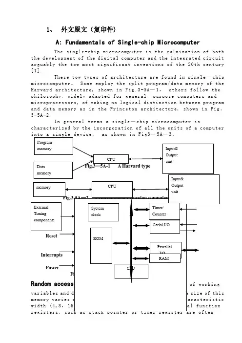
1、外文原文(复印件)A: Fundamentals of Single-chip MicrocomputerTh e si ng le-ch i p mi cr oc om pu ter is t he c ul mi nat i on o f bo th t h e d ev el op me nt o f th e d ig it al com p ut er an d t he int e gr at ed ci rc ui ta r gu ab ly th e t ow m os t s i gn if ic ant i nv en ti on s o f t h e 20t h c en tu ry[1].Th es e to w t ype s o f a rc hi te ct ur e a re fo un d i n s i ng le—ch ip m i cr oc om pu te r。
S o me em pl oy th e s p li t p ro gr am/d at a me mo ry of t he H a rv ar d ar ch it ect u re, sh ow n in Fi g.3-5A—1,ot he r s fo ll ow t hep h il os op hy, wi del y a da pt ed f or ge n er al—pu rp os e c o mp ut er s an dm i cr op ro ce ss or s, of ma ki ng no lo gi c al di st in ct io n be tw ee n p ro gr am a n d da ta m em or y a s i n th e Pr in cet o n ar ch it ec tu re,sh ow n in F ig。
3-5A-2.In g en er al te r ms a s in gl e—ch i p mi cr oc om pu ter isc h ar ac te ri zed b y the i nc or po ra tio n of al l t he uni t s o f a co mp ut er i n to a s in gl e de v i ce,as s ho wn i n F ig3—5A—3。

附件1:外文资料翻译译文大容量存储器由于计算机主存储器的易失性和容量的限制, 大多数的计算机都有附加的称为大容量存储系统的存储设备, 包括有磁盘、CD 和磁带。
相对于主存储器,大的容量储存系统的优点是易失性小,容量大,低成本, 并且在许多情况下, 为了归档的需要可以把储存介质从计算机上移开。
术语联机和脱机通常分别用于描述连接于和没有连接于计算机的设备。
联机意味着,设备或信息已经与计算机连接,计算机不需要人的干预,脱机意味着设备或信息与机器相连前需要人的干预,或许需要将这个设备接通电源,或许包含有该信息的介质需要插到某机械装置里。
大量储存器系统的主要缺点是他们典型地需要机械的运动因此需要较多的时间,因为主存储器的所有工作都由电子器件实现。
1. 磁盘今天,我们使用得最多的一种大量存储器是磁盘,在那里有薄的可以旋转的盘片,盘片上有磁介质以储存数据。
盘片的上面和(或)下面安装有读/写磁头,当盘片旋转时,每个磁头都遍历一圈,它被叫作磁道,围绕着磁盘的上下两个表面。
通过重新定位的读/写磁头,不同的同心圆磁道可以被访问。
通常,一个磁盘存储系统由若干个安装在同一根轴上的盘片组成,盘片之间有足够的距离,使得磁头可以在盘片之间滑动。
在一个磁盘中,所有的磁头是一起移动的。
因此,当磁头移动到新的位置时,新的一组磁道可以存取了。
每一组磁道称为一个柱面。
因为一个磁道能包含的信息可能比我们一次操作所需要得多,所以每个磁道划分成若干个弧区,称为扇区,记录在每个扇区上的信息是连续的二进制位串。
传统的磁盘上每个磁道分为同样数目的扇区,而每个扇区也包含同样数目的二进制位。
(所以,盘片中心的储存的二进制位的密度要比靠近盘片边缘的大)。
因此,一个磁盘存储器系统有许多个别的磁区, 每个扇区都可以作为独立的二进制位串存取,盘片表面上的磁道数目和每个磁道上的扇区数目对于不同的磁盘系统可能都不相同。
磁区大小一般是不超过几个KB; 512 个字节或1024 个字节。

本科毕业论文图像分割技术研究Survey on the image segmentation学院名称:电气信息工程学院专业班级:电子信息工程0601班2010年 6 月图像分割技术研究摘要图像分割是图像分析的第一步,是计算机视觉的基础,是图像理解的重要组成部分,也是图像处理、模式识别等多个领域中一个十分重要且又十分困难的问题。
在图像处理过程中,原有的图像分割方法都不可避免的会产生误差,这些误差会影响到图像处理和识别的效果。
遗传算法作为一种求解问题的高效并行的全局搜索方法,以其固有的鲁棒性、并行性和自适应性,使之非常适于大规模搜索空间的寻优,已广泛应用许多学科及工程领域。
在计算机视觉领域中的应用也正日益受到重视,为图像分割问题提供了新而有效的方法。
本文对遗传算法的基本概念和研究进展进行了综述;重点阐述了基于遗传算法的最大类间方差进行图像分割算法的原理、过程,并在MATLAB中进行了仿真实现。
实验结果表明基于遗传算法的最大类间方差方法的分割速度快,轮廓区域分割明显,分割质量高,达到了预期目的。
关键字:图像分割;遗传算法;阈值分割Survey on the image segmentationAbstract I mage segmentation is the first step of image processing and the basic of computer vision. It is an important part of the image, which is a very important and difficult problem in the field of image processing, pattern recognition.In image processing process, the original method of image segmentation can produce inevitable errors and these errors can affect the effect of image processing and identification .This paper discusses the current situation of the genetic algorithms used in the image segmentation and gives some kind of principles and the processes on genetic algorithm of image segmentationIn this paper.It also descripts the basic concepts and research on genetic algorithms .It emphasizes the algorithm based on genetic and ostu and realizes the simulation on Matlab. The experimental results show that this method works well in segmentation speed,the outline of the division and separate areas of high quality and achieve the desired effect.Genetic algorithm (GA) is a sort of efficient,paralled,full search method with its inherent virtues of robustness,parallel and self-adaptive characters. It is suitable for searching the optimization result in the large search space. Now it has been applied widely and perfectly in many study fields and engineering areas. In computer vision field GA is increasingly attached more importance. It provides the image segmentation a new and effective method.Key words image segmentation;genetic algorithm;image threshold segmentation目录第一章绪论 (1)1.1本课题研究的背景、目的与意义 (1)1.2本课题研究的现状与前景 (2)1.3本论文的主要工作及内容安排 (3)第二章图像分割基本理论 (4)2.1图像分割基本概念 (4)2.2图像分割的体系结构 (4)2.3图像分割方法分类 (5)2.3.1阈值分割方法 (5)2.3.2边缘检测方法 (8)2.3.3区域提取方法 (9)2.3.4结合特定理论工具的分割方法 (10)2.4图像分割的质量评价 (11)第三章遗传算法相关理论 (12)3.1遗传算法的应用研究概况 (12)3.2遗传算法的发展 (12)3.3遗传算法的基本概念 (13)3.4遗传算法基本流程 (14)3.5遗传算法的构成 (14)3.5.1编码 (14)3.5.2确定初始群体 (14)3.5.3适应度函数 (15)3.5.4遗传操作 (15)3.5.5控制参数 (17)3.6遗传算法的特点 (18)第四章 MATLAB相关知识 (20)4.1MATLAB简介 (20)4.2MATLAB的主要功能 (20)4.3MATLAB的技术特点 (21)4.4遗传算工法具箱(S HEFFIELD工具箱) (22)第五章基于遗传算法的最大类间方差图像分割算法 (24)5.1最大类间方差法简介 (24)5.2基于遗传算法的最大类间方差图像分割 (25)5.3流程图 (26)5.4实验结果 (27)第六章总结与展望 (29)6.1全文工作总结 (29)6.2展望 (29)致谢 (30)参考文献 (31)附录 (32)第一章绪论1.1本课题研究的背景、目的与意义数字图像处理技术是一个跨学科的领域。
The Application of Visualization Technology in ElectricPower Automation SystemWang Chuanqi, Zou QuanxiElectric Power Automation System Department of Yantai Dongfang Electronics Information IndustryCo., Ltd.Abstract: Isoline chart is widely used chart. The authors have improved the existing isoline formation method, proposed a simple and practical isoline formation method, studied how to fill the isoline chart, brought about a feasible method of filling the isoline chart and discussed the application of isoline chart in electric power automation system.Key words: Visualization; Isoline; Electric power automation systemIn the electric power system industry, the dispatching of electric network becomes increasingly important along with the expansion of electric power system and the increasing demands of people towards electric power. At present, electric network dispatching automation system is relatively advanced and relieves the boring and heavy work for operation staff. However, there is a large amount or even oceans of information. Especially when there is any fault, a large amount of alarm information and fault information will flood in the dispatching center. Faced with massive data, operation staff shall rely on some simple and effective tool to quickly locate the interested part in order to grasp the operation state of the system as soon as possible and to predict, identify and remove fault.Meanwhile, the operation of electric power system needs engineers and analysts in the system to analyze a lot of data. The main challenge that a system with thousands of buses poses for electric power automation system is that it needs to supply a lot of data to users in a proper way and make users master and estimate the state of the system instinctively and quickly. This is the case especially in electric network analyzing software. For example, the displaying way of data is more important in analyzing the relations between the actual trend, planned trend of electric network and the transmission capacity of the system. The application of new computer technology and visualization technology in the electric power automation system can greatly satisfy new development and new demands of electric power automation system.The word “Visualization” originates from English “Visual” and itsoriginal meaning is visual and vivid. In fact, the transformation of any abstract things and processes into graphs and images can be regarded as visualization. But as a subject term, the word “Visualization” officially appeared in a seminar held by National Science Foundation (shortened as NSF) of the USA in February 1987. The official report published after the seminar defined visualization, its covered fields and its recent and long-term research direction, which symbolized that “Visualization” became mature as a subject at the international level.The basic implication of visualization is to apply the principles and methods of computer graphics and general graphics to transforming large amounts of data produced by scientific and engineering computation into graphs and images and displaying them in a visual way. It refers to multi research fields such as computer graphics, image processing, computer vision, computer-aided design (CAD) and graphical user interface (GUI), etc. and has become an important direction for the current research of computer graphics.There are a lot of methods to realize visualization and each method has its unique features and applies to different occasions. Isoline and isosurface is an important method in visualization and can be applied to many occasions. The realization of isoline (isosurface) and its application in the electric power automation system will be explained below in detail.1、 Isoline (Isosurface)Isoline is defined with all such points (x i, y i), in which F(x i, y i)=F i (F i is a set value), and these points connected in certain order form the isoline of F(x,y) whose value is F i…Common isolines such as contour line and isotherm, etc.are based on the measurement of certain height and temperature.Regular isoline drawing usually adopts grid method and the steps are as follows:gridingdiscrete data;converting grid points into numerical value;calculating isoline points; tracing isoline; smoothing and marking isoline; displaying isoline or filling the isoline chart. Recently, some people have brought about the method of introducing triangle grid to solve the problems of quadrilateral grid. What the two methods have in common is to use grid and isoline points on the grid for traveling tracing, which results in the following defects in the drawing process:(1) The two methods use the grid structure, first find out isoline pointson each side of certain quadrilateral grid or triangle grid, and then continue to find out isoline points from all the grids, during which a lot of judgment are involved, increasing the difficulty of program realization. When grid nodes become isoline points, they shall be treated as singular nodes, which not only reduces the graph accuracy but also increases the complexity of drawing.(2) The two methods produce drawn graphs with inadequate accuracy and intersection may appear during traveling tracing. The above methods deal with off-grid points using certain curve-fitting method. That is, the methods make two approximations and produce larger tolerance.(3) The methods are not universal and they can only deal with data of grid structure. If certain data is transformed into the grid structure, interpolation is needed in the process, which will definitely reduce the accuracy of graphs.To solve the problems, we adopt the method of raster graph in drawing isoline when realizing the system function, and it is referred to as non-grid method here. This method needs no grid structures and has the following advantages compared to regular methods:(1) Simple programming and easily realized, with no singular nodes involved and no traveling tracing of isoline. All these advantages greatly reduce the complexity of program design.(2)Higher accuracy. It needs one approximation while regular methods need two or more.(3) More universal and with no limits of grid1.1 Isoline Formation Method of Raster GraphThe drawing of raster graph has the following features: the area of drawing isoline is limited and is composed of non-continuous points. In fact, raster graph is limited by computer screen and what people can see is just a chart formed by thousands of or over ten thousand discrete picture elements. For example, a straight line has limited length on computers and is displayed with lots of discrete points. Due to the limitations of human eyes, it seemscontinuous. Based on the above features, this paper proposes isoline formation method of raster graph. The basic idea of this method is: as computer graphs are composed of discrete points, one just needs to find out all the picture element points on the same isoline, which will definitely form thisisoline.Take the isoline of rectangular mountain area for example to discuss detailed calculation method. Data required in calculation is the coordinates and altitude of each measuring point, i.e., (x i ,y i ,z i ), among which z i represents the altitude of No.i measuring point and there are M measuring points in total. Meanwhile, the height of isoline which is to be drawn is provided. For example, starting from h 0 , an isoline is drawn with every height difference of ∆h0 and total m isolines are drawn. Besides, the size of the screen area to be displayed is known and here (StartX,StartY) represents the top left corner of this area while (EndX ,EndY)represents the low right corner of this area. The calculation method for drawing its isoline is as follows:(1) Find out the value of x i and y i of the top left corner and low right corner points in the drawing area, which are represented by X max ,X min ,Y max ,Y min ;(2)Transform the coordinate (x i ,y i ) into screen coordinate (SX i ,SY i ) and the required transformation formula is as follows:sx i =x i -X min /X max -X min (EndX-StartX)sy i =y i -Y min /Y max -Y min (EndY-StartY)Fig. 1 Height computation sketch(3) i =startX,j=StartY; Suppose i =startX,j=StartY;(4) Use the method of calculating height (such as distance weighting method and least square method, etc.) to calculate out the height h 1, h 2, h 3 of points (i,j), (i+1,j) and (i,j+1), i.e., the height of the three points P 1, P 2 and P 3 in Fig. 1;(5) Check the value of h 1, h 2, h 3 and determine whether there is any isoline crossing according to the following methods:①k=1,h=h 0;①k=1,h=h 0;②Judge whether (P 1-h)*(P 2-h)≤0 is justified. If justified, continue the next step; otherwise, perform ⑤;③Judge whether |P1-h|=|P2-h| is justified. If justified, it indicates that there is an isoline crossing P1, P2, dot the two points and jumpto (6); otherwise, continue next step;④Judge whether |P1-h|<|P2-h|is justified. If justified, it indicates that there is an isoline crossing P1, dot this point; otherwise, dot P2;⑤Judge whether (P1-h)*(P3-h)≤0 is justified. If justified, continue next step; otherwise, perform ⑧.⑥Judge whether|P1-h|=|P3-h|is justified. If justified, dot the twopoints P1\,P3 and jump to (6);otherwise, jump to ⑤;⑦Judge whether|P1-h|<|P3-h|is justified. If justified, dot P1; otherwise, dot P3;⑧Suppose k:=k+1 and judge whether k<m+1 I is justified. If unjustified, continue next step; otherwise, suppose h:=h+∆h0 and return to ②.(6) Suppose j:j+1 and judge whether j<EndY is justified. If unjustified,continue next step; otherwise, return to (4);(7) Suppose i:=i+1 and judge whether i<EndX is justified. If unjustified,continue next step; otherwise, return to (4);(8) The end.In specific program design, in order to avoid repeated calculation, an array can be used to keep all the value of P2 in Column i+1 and another variable is used to keep the value of P3.From the above calculation method, it can be seen th at this method doesn’tinvolve the traveling of isoline, the judgment of grid singular nodes and theconnection of isoline, etc., which greatly simplifies the programming and iseasily realized, producing no intersection lines in the drawn chart.1.2 Griding and Determining NodesTime consumption of a calculation method is of great concern. Whencalculating the height of (i,j), all the contributing points to the height ofthis point need to be found out. If one searches through the whole array, it is very time consuming. Therefore, the following regularized grid method is introduced to accelerate the speed.First, two concepts, i.e., influence domain and influence point set, are provided and defined as follows: Definition 1: influence domain O(P) of node P refers to the largest area in which this nodes has some influence on other nodes. In this paper, it can refer to the closed disc with radius as r (predetermined) or the square with side length as a (predetermined).Definition 2: influence point set S(P)of node P refers to the collection of all the nodes which can influence node P. In this paper, it refers to the point set with the number of elements as n (predetermined), i.e., the number of all the known contributing nodes to the height of node (i,j) can only be n and these nodes are generally n nodes closet to node P.According to the above definition, in order to calculate out the height of any node (i,j), one just needs to find out all the nodes influencing the height of this node and then uses the interpolation method according totwo-dimensional surface fitting. Here, we will explain in detail how to calculate out the height of node (i,j) with Definition 1, i.e., the method of influence domain, and make similar calculation with Definition 2.Grid structure is used to determine other nodes in the influence domainof node (i,j). Irregular area is covered with regular grid, in which the grids have the same size and the side of grid is parallel with X axis and Y axis. The grid is described as follows:(x min,x max,NCX)(y min,y max,NCY)In the formula, x min, y max and x max, y max are respectively the minimum and maximum coordinates of x, y direction of the area; NCX is the number of grids in X direction; NCY is the number of grids in Y direction.Determining which grid a node belongs to is performed in the following two steps. Suppose the coordinate of this node is (x,y). First, respectively calculate its grid No. in x direction and y direction, and the formula is as follows:IX=NCX*(x-x min)/(xmax-x min)+1;IY=NCY(y-y min)/(y max-y min)+1。
matlab图像处理外文翻译外文文献附录A 英文原文Scene recognition for mine rescue robotlocalization based on visionCUI Yi-an(崔益安), CAI Zi-xing(蔡自兴), WANG Lu(王璐)Abstract:A new scene recognition system was presented based on fuzzy logic and hidden Markov model(HMM) that can be applied in mine rescue robot localization during emergencies. The system uses monocular camera to acquire omni-directional images of the mine environment where the robot locates. By adopting center-surround difference method, the salient local image regions are extracted from the images as natural landmarks. These landmarks are organized by using HMM to represent the scene where the robot is, and fuzzy logic strategy is used to match the scene and landmark. By this way, the localization problem, which is the scene recognition problem in the system, can be converted into the evaluation problem of HMM. The contributions of these skills make the system have the ability to deal with changes in scale, 2D rotation and viewpoint. The results of experiments also prove that the system has higher ratio of recognition and localization in both static and dynamic mine environments.Key words: robot location; scene recognition; salient image; matching strategy; fuzzy logic; hidden Markov model1 IntroductionSearch and rescue in disaster area in the domain of robot is a burgeoning and challenging subject[1]. Mine rescue robot was developed to enter mines during emergencies to locate possible escape routes for those trapped inside and determine whether it is safe for human to enter or not. Localization is a fundamental problem in this field. Localization methods based on camera can be mainly classified into geometric, topological or hybrid ones[2]. With its feasibility and effectiveness, scene recognition becomes one of the important technologies of topological localization.Currently most scene recognition methods are based on global image features and have two distinct stages: training offline and matching online.。
第 1 页中英文对照资料外文翻译文献原 文To image edge examination algorithm researchAbstract :Digital image processing took a relative quite young discipline,is following the computer technology rapid development, day by day obtains th widespread application.The edge took the image one kind of basic characteristic,in the pattern recognition, the image division, the image intensification as well as the image compression and so on in the domain has a more widesp application.Image edge detection method many and varied, in which based on brightness algorithm, is studies the time to be most long, the theory develo the maturest method, it mainly is through some difference operator, calculates its gradient based on image brightness the change, thus examines the edge, mainlyhas Robert, Laplacian, Sobel, Canny, operators and so on LOG 。
规范化切割和图像分割摘要:为解决在视觉上的感知分组的问题,我们提出了一个新的方法。
我们目的是提取图像的总体印象,而不是只集中于局部特征和图像数据的一致性。
我们把图像分割看成一个图形的划分问题,并且提出一个新的分割图形的全球标准,规范化切割。
这一标准衡量了不同组之间的总差异和总相似。
我们发现基于广义特征值问题的一个高效计算技术可以用于优化标准。
我们已经将这种方法应用于静态图像和运动序列,发现结果是令人鼓舞的。
1简介近75年前,韦特海默推出的“格式塔”的方法奠定了感知分组和视觉感知组织的重要性。
我的目的是,分组问题可以通过考虑图(1)所示点的集合而更加明确。
Figure1:H<iw m.3Uiyps?通常人类观察者在这个图中会看到四个对象,一个圆环和内部的一团点以及右侧两个松散的点团。
然而这并不是唯一的分割情况。
有些人认为有三个对象,可以将右侧的两个认为是一个哑铃状的物体。
或者只有两个对象,右侧是一个哑铃状的物体,左侧是一个类似结构的圆形星系。
如果一个人倒行逆施,他可以认为事实上每一个点是一个不同的对象。
这似乎是一个人为的例子,但每一次图像分割都会面临一个相似的问题一将一个图像的区域D划分成子集Di会有许多可能的划分方式(包括极端的将每一个像素认为是一个单独的实体)。
我们怎样挑选“最正确”的呢?我们相信贝叶斯的观点是合适的,即一个人想要在较早的世界知识背景下找到最合理的解释。
当然,困难在于具体说明较早的世界知识一一些低层次的,例如亮度,颜色,质地或运行的一致性,但是关于物体对称或对象模型的中高层次的知识是同等重要的。
这些表明基于低层次线索的图像分割不能够也不应该旨在产生一个完整的最终的正确的分割。
目标应该是利用低层次的亮度,颜色,质地,或运动属性的一致性继续的提出分层分区。
中高层次的知识可以用于确认这些分组或者选择更深的关注。
这种关注可能会导致更进一步的再分割或分组。
关键点是图像分割是从大的图像向下进行,而不是像画家首先标示出主要区域,然后再填充细节。
数字图象处理英文原版及翻译Digital Image Processing: English Original Version and TranslationIntroduction:Digital Image Processing is a field of study that focuses on the analysis and manipulation of digital images using computer algorithms. It involves various techniques and methods to enhance, modify, and extract information from images. In this document, we will provide an overview of the English original version and translation of digital image processing materials.English Original Version:The English original version of digital image processing is a comprehensive textbook written by Richard E. Woods and Rafael C. Gonzalez. It covers the fundamental concepts and principles of image processing, including image formation, image enhancement, image restoration, image segmentation, and image compression. The book also explores advanced topics such as image recognition, image understanding, and computer vision.The English original version consists of 14 chapters, each focusing on different aspects of digital image processing. It starts with an introduction to the field, explaining the basic concepts and terminology. The subsequent chapters delve into topics such as image transforms, image enhancement in the spatial domain, image enhancement in the frequency domain, image restoration, color image processing, and image compression.The book provides a theoretical foundation for digital image processing and is accompanied by numerous examples and illustrations to aid understanding. It also includes MATLAB codes and exercises to reinforce the concepts discussed in each chapter. The English original version is widely regarded as a comprehensive and authoritative reference in the field of digital image processing.Translation:The translation of the digital image processing textbook into another language is an essential task to make the knowledge and concepts accessible to a wider audience. The translation process involves converting the English original version into the target language while maintaining the accuracy and clarity of the content.To ensure a high-quality translation, it is crucial to select a professional translator with expertise in both the source language (English) and the target language. The translator should have a solid understanding of the subject matter and possess excellent language skills to convey the concepts accurately.During the translation process, the translator carefully reads and comprehends the English original version. They then analyze the text and identify any cultural or linguistic nuances that need to be considered while translating. The translator may consult subject matter experts or reference materials to ensure the accuracy of technical terms and concepts.The translation process involves several stages, including translation, editing, and proofreading. After the initial translation, the editor reviews the translated text to ensure its coherence, accuracy, and adherence to the target language's grammar and style. The proofreader then performs a final check to eliminate any errors or inconsistencies.It is important to note that the translation may require adapting certain examples, illustrations, or exercises to suit the target language and culture. This adaptation ensures that the translated version resonates with the local audience and facilitates better understanding of the concepts.Conclusion:Digital Image Processing: English Original Version and Translation provides a comprehensive overview of the field of digital image processing. The English original version, authored by Richard E. Woods and Rafael C. Gonzalez, serves as a valuable reference for understanding the fundamental concepts and techniques in image processing.The translation process plays a crucial role in making this knowledge accessible to non-English speakers. It involves careful selection of a professional translator, thoroughunderstanding of the subject matter, and meticulous translation, editing, and proofreading stages. The translated version aims to accurately convey the concepts while adapting to the target language and culture.By providing both the English original version and its translation, individuals from different linguistic backgrounds can benefit from the knowledge and advancements in digital image processing, fostering international collaboration and innovation in this field.。
3-电气工程及其自动化专业外文文献英文文献外文翻译1、外文原文(复印件)A: Fundamentals of Single-chip MicrocomputerThe single-chip microcomputer is the culmination of both the development of the digital computer and the integrated circuit arguably the tow most significant inventions of the 20th century [1].These tow types of architecture are found in single-chip microcomputer. Some employ the split program/data memory of the Harvard architecture, shown in Fig.3-5A-1, others follow the philosophy, widely adapted for general-purpose computers and microprocessors, of making no logical distinction between program and data memory as in the Princeton architecture, shown in Fig.3-5A-2.In general terms a single-chip microcomputer is characterized by the incorporation of all the units of a computer into a single device, as shown in Fig3-5A-3.ProgramInput& memoryOutputCPU unitDatamemoryFig.3-5A-1 A Harvard typeInput&Output CPU memoryunitFig.3-5A-2. A conventional Princeton computerExternal Timer/ System Timing Counter clock componentsSerial I/OReset ROMPrarallelI/OInterrupts RAMCPUPowerFig3-5A-3. Principal features of a microcomputerRead only memory (ROM).ROM is usually for the permanent,non-volatile storage of an applications program .Many microcomputers and microcontrollers are intended for high-volume applications and hence the economical manufacture of the devices requires that the contents of the program memory be committed permanently during the manufacture of chips . Clearly, this implies a rigorous approach to ROM code development since changes cannot be made after manufacture .This development process may involve emulation using a sophisticated development system with a hardware emulation capability as well as the use of powerful software tools.Some manufacturers provide additional ROM options by including in their range devices with (or intended for use with) user programmablememory. The simplest of these is usually device which can operate in a microprocessor mode by using some of the input/output lines as an address and data bus for accessing external memory. This type of device can behave functionally as the single chip microcomputer from which itis derived albeit with restricted I/O and a modified external circuit. The use of these ROMlessdevices is common even in production circuits where the volume does not justify the development costs of custom on-chip ROM[2];there canstill be a significant saving in I/O and other chips compared to a conventional microprocessor based circuit. More exact replacement for ROM devices can be obtained in the form of variants with 'piggy-back' EPROM(Erasable programmable ROM )sockets or devices with EPROM instead of ROM 。
原文出处Digital Image Processing 2/E图像分割前一章的资料使我们所研究的图像处理方法开始发生了转变。
从输人输出均为图像的处理方法转变为输人为图像而输出为从这些图像中提取出来的属性的处理方法〔这方面在1.1节中定义过)。
图像分割是这一方向的另一主要步骤。
分割将图像细分为构成它的子区域或对象。
分割的程度取决于要解决的问题。
就是说当感兴趣的对象已经被分离出来时就停止分割。
例如,在电子元件的自动检测方面,我们关注的是分析产品的图像,检测是否存在特定的异常状态,比如,缺失的元件或断裂的连接线路。
超过识别这此元件所需的分割是没有意义的。
异常图像的分割是图像处理中最困难的任务之一。
精确的分割决定着计算分析过程的成败。
因此,应该特别的关注分割的稳定性。
在某些情况下,比如工业检测应用,至少有可能对环境进行适度控制的检测。
有经验的图像处理系统设计师总是将相当大的注意力放在这类可能性上。
在其他应用方面,比如自动目标采集,系统设计者无法对环境进行控制。
所以,通常的方法是将注意力集中于传感器类型的选择上,这样可以增强获取所关注对象的能力,从而减少图像无关细节的影响。
一个很好的例子就是,军方利用红外线图像发现有很强热信号的目标,比如移动中的装备和部队。
图像分割算法一般是基于亮度值的不连续性和相似性两个基本特性之一。
第一类性质的应用途径是基于亮度的不连续变化分割图像,比如图像的边缘。
第二类的主要应用途径是依据事先制定的准则将图像分割为相似的区域,门限处理、区域生长、区域分离和聚合都是这类方法的实例。
本章中,我们将对刚刚提到的两类特性各讨论一些方法。
我们先从适合于检测灰度级的不连续性的方法展开,如点、线和边缘。
特别是边缘检测近年来已经成为分割算法的主题。
除了边缘检测本身,我们还会讨论一些连接边缘线段和把边缘“组装”为边界的方法。
关于边缘检测的讨论将在介绍了各种门限处理技术之后进行。
门限处理也是一种人们普遍关注的用于分割处理的基础性方法,特别是在速度因素占重要地位的应用中。
关于门限处理的讨论将在几种面向区域的分割方法展开的讨论之后进行。
之后,我们将讨论一种称为分水岭分割法的形态学图像分割方法。
这种方法特别具有吸引力,因为它将本章第一部分提到的几种分割属性技术结合起来了。
我们将以图像分割的应用方面进行讨论来结束本章。
10.1间断检测在本节中,我们介绍几种用于检测数字图像中三种基本的灰度级间断技术:点、线和边缘。
寻找间断最一般的方法是以3.5节中描述的方式对整幅图像使用一个模板进行检测。
图10-1所示的3x3模板,这一过程包括计算模板所包围区域内灰度级与模板系数的乘积之和。
就是说,关于式(3.5.3),在图像中任意点的模板响应由下列公式给出:∑==+++=9199...2211i wiziz w z w z w R (10.1.1)图10-1 一个一般的3*3模板这里Zi 是与模板系数Wi 相联系的像素的灰度级。
照例,模板响应是它的中心位置。
有关执行模板操作的细节在3.5节中讨论。
10.1.1点检测在一幅图像中,孤立点的检测在理论上是简单的。
使用如图10-2(a)所示的模板,如果|R| ≥ T (10.1.2)我们说在模板中心的位置上已经检测到一个点。
这里T 是一个非负门限,R 由式(10.1.1)给出。
基本上,这个公式是测量中心点和它的相邻点之间加权的差值。
基本思想就是:如果一个孤立的点(此点的灰度级与其背景的差异相当大并且它所在的位置是一个均匀的或近似均匀的区域)与它周围的点很不相同,则很容易被这类模板检测到。
注意,图10-2(a)中的模板同图3.39(d)中给出的模板在拉普拉斯操作方而是相同的。
严格地讲,这里强调的是点的检测。
即我们着重考虑的差别是那些足以识别为孤立点的差异(由T决定)。
注意,模板系数之和为零表示在灰度级为常数的区域,模板响应为零。
-1 -1 -1-1 8 -1-1 -1 -1(a)(b)(c)(d)图10-2 (a)点检测模板,(b)带有通孔的涡轮叶片的X射线,(c)点检测的结果,(d)使用式(10.1.2)得到的结果(原图由X-TEK系统公司提供)例10.1图像中孤立点的检浏我们以图10-2(b)功为辅助说明如何从一幅图中将孤立点分割出来.这幅X射线图显示了一个带有通孔的喷气发动抓涡枪叶片,通孔位于圈像的右上象限。
在孔中只嵌有一个黑色像素。
图10-2(c)是将点检测模板应用于X射线图像后得到的结果.图10-2(d)显示了当T取图10-2(c)中像素最高绝衬值的90%时,应用式(10.1.2)所得的结果(门限选择将在10.3节中详细讨论)。
图中的这个单一的像素清晰可见(这个像素被人为放大以便印刷后可以看到)。
由于这类检测是基于单像素间断,并且检测器模板的区域有一个均匀的背景,所以这个检测过程是相当有专用性的当这一条件不能满足时,本章中计论的其他方法会更适合检测灰度级间断10.1.2线检测复杂程度更高一级的检测是线检测,考虑图10-3中显示的模板。
如果第l 个模板在图像中移动,这个模板将对水平方向的线条(一个像素宽度)有更强的响应。
在一个不变的背景上,当线条经过模板的中间一行时会产生响应的最大值。
画一个元素为1的简单阵列,并且使具有不同灰度级(如5)的一行水平穿过阵列,可以很容易验证这一点。
同样的实验可以显示出图10-3中的第2个模板对于45°方向线有最佳响应;第3个模板对于垂直线有最佳响应;第4个模板对于-45°方向线有最佳响应;这些方向也可以通过注释每个模板的优选方向来设置,即在这些方向上用比别的方向更大的系数(为2)设置权值。
注意每个模板系数相加的总和为零,表示在灰度级恒定的区域来自模板的响应为零。
°图10-3 线模板令R1,R2,R3和R4。
从左到右代表图10-3中模板的响应,这里R的值由式(10.1.1)给出。
假设4个模板分别应用于一幅图像,在图像中心的点,如果|Ri|>|Rj| ,j≠i,则此点被认为与在模板i方向上的线更相关。
例如,如果在图中的一点有|Ri|>|Rj| ,j=2,3,4,我们说此特定点与水平线有更大的联系。
换句话说,我们可能对检测特定方向上的线感兴趣。
在这种情况下,我们应使用与这一方向有关的模板,并设置该模板的输出门限,如式(10.1.2)所示。
换句话说,如果我们对检测图像中由给定模板定义的方向上的所有线感兴趣.只需要简单地通过整幅图像运行模板,并对得到的结果的绝对值设置门限即可。
留下的点是有最强响应的点。
对于一个像素宽度的线,这些响应最靠近模板定义的对应方向。
下列例子说明了这一过程。
例 10.2特定方向上的线检测图10-4(a)显示了一幅电路接线模板的数字化(二值的)图像。
假设我们要找到一个像素宽度的并且方向为-45°的线条。
基于这个假设,使用图10-3中最后一个模板。
图10-4(b)显示了得到的结果的绝对值。
注意,图像中所有水平和垂直的部分都被除去了。
并且在图10-4(b)中所有原图中接近-45°方向的部分产生了最强响应。
(a)(b)(c)图10-4 线检测的说明。
(a)二进制电路接线模板,(b)使用-45°线检测器处理后得到的绝对值,(c)对图像(b)设置门限得到的结果为了决定哪一条线拟合模板最好,只需要简单地对图像设置门限。
图10-4(c)显示了使门限等于图像中最大值后得到的结果。
对于与这个例子类似的应用,让门限等于最大值是一个好的选择,因为输入图像是二值的,并且我们要寻找的是最强响应。
图10-4(c)显示了在白色区所有通过门限检测的点。
此时,这一过程只提取了一个像素宽且方向为-45°的线段(图像中在左上象限中也有此方向上的图像部分,但宽度不是一个像素)。
图10-4(c)中显示的孤立点是对于模板也有相同强度响应的点。
在原图中,这些点和与它们紧接着的相邻点,是用模板在这些孤立位置上生成最大响应的方法来定向的。
这些孤立点也可以使用图10-2(a)中的模板进行检测,然后删除,或者使用下一章中讨论的形态学腐蚀法删除。
10.1.3边缘检侧尽管在任何关于分割的讨论中,点和线检测都是很重要的,但是边缘检测对于灰度级间断的检测是最为普遍的检测方法。
本节中,我们讨论实现一阶和二阶数字导数检测一幅图像中边缘的方法。
在3.7节介绍图像增强的内容中介绍过这些导数。
本节的重点将放在边缘检测的特性上。
某些前面介绍的概念在这里为了叙述的连续性将进行简要的重述。
基本说明在3.7.1节中我们非正式地介绍过边缘。
本节中我们更进一步地了解数字化边缘的概念。
直观上,一条边缘是一组相连的像素集合。
这些像素位于两个区域的边界上。
然而,我们已经在2.5.2节中用一定的篇幅解释了一条边缘和一条边界的区别。
从根本上讲,如我们将要看到的,一条边缘是一个“局部”概念,而由于其定义的方式,一个区域的边界是一个更具有整体性的概念。
给边缘下一个更合理的定义需要具有以某种有意义的方式测量灰度级跃变的能力。
我们先从直观上对边缘建模开始。
这样做可以将我们引领至一个能测量灰度级有意义的跃变的形式体系中。
从感觉上说,一条理想的边缘具有如图10-5(a)所示模型的特性。
依据这个模型生成的完美边缘是一组相连的像素的集合(此处为在垂直方向上),每个像素都处在灰度级跃变的一个垂直的台阶上(如图形中所示的水平剖面图)。
实际上,光学系统、取样和其他图像采集的不完善性使得到的边缘是模糊的,模糊的程度取决于诸如图像采集系统的性能、取样率和获得图像的照明条件等因素。
结果,边缘被更精确地模拟成具有“类斜面”的剖面,如图10-5(b)所示。
斜坡部分与边缘的模糊程度成比例。
在这个模型中,不再有细线(一个像素宽的线条)。
相反,现在边缘的点是包含于斜坡中的任意点,并且边缘成为一组彼此相连接的点集。
边缘的“宽度”取决于从初始灰度级跃变到最终灰度级的斜坡的长度。
这个长度又取决于斜度,斜度又取决于模糊程度。
这使我们明白:模糊的边缘使其变粗而清晰的边缘使其变得较细。
图10-6(a)显示的图像是从图10-5(b)的放大特写中提取出来的。
图10-6(b)显示了两个区域之间边缘的一条水平的灰度级剖面线。
这个图形也显示出灰度级剖面线的一阶和二阶导数。
当我们沿着剖面线从左到右经过时,在进人和离开斜面的变化点,一阶导数为正。
在灰度级不变的区域一阶导数为零。
在边缘与黑色一边相关的跃变点二阶导数为正,在边缘与亮色一边相关的跃变点二阶导数为负,沿着斜坡和灰度为常数的区域为零。
在图10-6(b)中导数的符号在从亮到暗的跃变边缘处取反。
(a)(b)图10-5 (a)理想的数字边缘模型,(b)斜坡数字边缘模型。
斜坡部分与边缘的模糊程度成正比图10-6 (a)由一条垂直边缘分开的两个不同区域,(b)边界附近的细节显示了一个灰度级剖面图和一阶与二阶导数的剖面图由这些现象我们可以得到的结论是:一阶导数可以用于检测图像中的一个点是否是边缘的点(也就是判断一个点是否在斜坡上)。