电子信息工程中英文翻译
- 格式:doc
- 大小:90.00 KB
- 文档页数:24

Unit 12 生物识别技术Unit 12-1第一部分:指纹识别在所有的生物技术中,指纹识别是最早期的一种技术。
我们知道,每个人都有自己独特的、不可变更的指纹。
指纹是由手指表皮上的一系列峰谷组成的。
指纹的独特性是由这些峰谷的形状以及指纹的细节点所决定的。
指纹的细节点是指纹局部凸起处的一些特性,这些特性出现在凸起的分叉处或是凸起的截止处。
指纹匹配技术可以被分为两类:基于细节的指纹匹配技术和基于相关性的指纹匹配技术。
基于细节的指纹匹配首先要找出细节点,然后在手指上对应出与它们相关的位置,如图12.1所示。
但是,使用这种方法存在一些困难。
要精确地提取指纹的细节点是很困难的。
而且,这种方法不能很好地考虑指纹峰谷的整体形状。
基于相关性的指纹匹配技术可以解决部分基于细节的指纹匹配方法存在的问题,但它也存在一些自身的缺陷。
基于相关性的匹配技术需要给出已注册过的特征点的精确位置,并且该方法会受图像平移和旋转的影响。
图12.1 基于细节的指纹匹配基于细节的指纹匹配技术在匹配不同大小的细节模型时(未注册过的)会存在一些问题。
指纹上局部的凸起结构不能完全由指纹细节实现特征化。
我们可以尝试另一种表达指纹的方法,它可以获得更多的指纹局部信息并且得到固定长度的指纹编码。
于是,我们只需要计算两个指纹编码之间的欧几里得距离,匹配过程有望变得相对简单。
研发对于指纹图像中噪声更稳健并能实时提供更高精度的算法是重要的。
商用指纹(身份)认证系统对给定的错误接受率要求具有很低的错误拒绝率。
在这点上,任何一项简单的技术都很难实现。
我们可以从不同的匹配技术中汇总多个证据从而提高系统的总体精确度。
在实际应用中,传感器、采集系统、性能随时间的变化是关键因素。
为了评价系统性能,我们有必要对少数使用者在一段时间内进行现场试验。
每天我们可以从法医鉴定、出入口控制、驾驶证登记等多个方面的应用中采集并保存大量的指纹。
基于指纹的自动识别系统需要把输入的指纹与数据库中大量的指纹进行匹配验证。


电子信息工程专业课程名称中英文翻译对照(2009级培养计划)实践环节翻译高等数学Advanced Mathematics 大学物理College Physics线性代数Linear Algebra复变函数与积分变换Functions of Complex Variable and Integral Transforms概率论与随机过程Probability and Random Process 物理实验Experiments of College Physics数理方程Equations of Mathematical Physics电子信息工程概论Introduction to Electronic and Information Engineering计算机应用基础Fundamentals of Computer Application 电路原理Principles of Circuit模拟电子技术基础Fundamentals of Analog Electronics数字电子技术基础Fundamentals of Digital ElectronicsC语言程序设计The C Programming Language信息论基础Fundamentals of Information Theory 信号与线性系统Signals and Linear Systems微机原理与接口技术Microcomputer Principles and Interface Technology马克思主义基本原理Fundamentals of Marxism毛泽东思想、邓小平理论和“三个代表”重要思想概论Thoughts of Mao and Deng中国近现代史纲要Modern Chinese History思想道德修养与法律基础Moral Education & Law Basis形势与政策Situation and Policy英语College English体育Physical Education当代世界经济与政治Modern Global Economy and Politics 卫生健康教育Health Education心理健康知识讲座Psychological Health Knowledge Lecture公共艺术课程Public Arts文献检索Literature Retrieval军事理论Military Theory普通话语音常识及训练Mandarin Knowledge and Training大学生职业生涯策划(就业指导)Career Planning (Guidance of Employment )专题学术讲座Optional Course Lecture科技文献写作Sci-tech Document Writing高频电子线路High-Frequency Electronic Circuits通信原理Communications Theory数字信号处理Digital Signal Processing计算机网络Computer Networks电磁场与微波技术Electromagnetic Field and MicrowaveTechnology现代通信技术Modern Communications TechnologyDSP原理及应用Principles and Applications of DSP单片机原理Principles of Microcontroller嵌入式系统Embedded Systems数字图像处理Digital Image Processing检测与转换技术Signal Detection and Conversion Technology 电子设计自动化Electronics Design Automation现代信息处理技术Modern Information Processing Technology 语音信号处理Speech Signal Processing虚拟仪器基础(双语)Fundamentals of Virtual InstrumentMatlab语言及应用Matlab Language and Application电子系统设计Electronics System Design电磁兼容理论Electromagnetic Compatibility Theory电子设计自动化Electronics Design Automation检测与转换技术Signal Detection and Conversion Technology 智能仪器Intelligent Instrument Design自动控制原理Automatic Control Systems无线传感器网络Wireless Sensor Networks无线局域网Wireless Local Area Networks计算机网络组网技术Computer Network Construction Technology 现代通信网Modern Communication NetworksAdvanced MathematicsCollege Physics计算机应用基础Fundamentals of Computer Application 电路原理Principles of Circuit模拟电子技术基础Fundamentals of Analog Electronics数字电子技术基础Fundamentals of Digital ElectronicsC语言程序设计The C Programming Language信号与线性系统Signals and Linear Systems微机原理与接口技术Microcomputer Principles and Interface Technology高频电子线路High-Frequency Electronic Circuits 通信原理Communications Theory数字信号处理Digital Signal Processing计算机网络Computer Networks电磁场与微波技术Electromagnetic Field and Microwave TechnologyDSP原理及应用Principles and Applications of DSP 单片机原理Principles of Microcontroller嵌入式系统Embedded Systems自动控制原理Automatic Control Systems。

1 The transistor is what started the evolution of the modern computer industry in motion.晶体管开启了现代电脑工业的革命2 The storage cell only requires one capacitor and one transistor, whereas a flip-flop connected in an array requires 6 transistors.存储单元仅需要一个电容和晶体管,并而不像触发器整列那样需要6个晶体管3 There has been a never ending series of new op amps released each year since then, and their performance and reliability has improved to the point where present day op amps can be used for analog applications by anybody.从此以后每年都有新系列的运放发布,他们的性能和可靠性得到了提升,如今任何人都能用运放来设计模拟电路。
4 This is capable of very high speed conversion and thus can accommodate high sampling rates, but in its basic form is very power hungry.它具有高速转换能力,从而能适应高速采样速率,但它的基本形式非常耗电。
5 During the “on” period , energy is being stored within the core material of the inductor in the form of flux.在”on”阶段,能量以涌浪形式存储在电感的核芯材料里面6 The design goal of frequency synthesizers is to replace multiple oscillators in a system, and hence reduce board space and cost.频率合成器的设计目标是取代系统中多个振荡器,从而减小板卡面积和成本。

电子信息工程专业英语教程第三版译者:唐亦林p32In 1945 H. W. Bode presented a system for analyzing the stability of feedback systems by using graphical methods. Until this time, feedback analysis was done by multiplication and division, so calculation of transfer functions was a time consuming and laborious task. Remember, engineers did not have calculators or computers until the '70s. Bode presented a log technique that transformed the intensely mathematical process of calculating a feedback system's stability into graphical analysis that was simple and perceptive. Feedback system design was still complicated, but it no longer was an art dominated by a few electrical engineers kept in a small dark room. Any electrical engineer could use Bode's methods find the stability of a feedback circuit, so the application of feedback to machines began to grow. There really wasn't much call for electronic feedback design until computers and transducers become of age.1945年HW伯德提出了一套系统方法,用图形化方法来分析反馈系统的稳定性。

1.As data networks advanced…also grew more complex.由于数据网络从面向终端的系统向分组交换、计算机与计算机连接的方向发展, 执行网络功能所必需的协议也变得愈来愈复杂。
2.An additional bit called a parity bit…during transmission.在每个字符的后面有时还包括一个称为奇偶校验位的附加位, 它们测试数据位在传输过程中是否被意外改变。
3.As already stated, with…downlink(FDD paired bands).如前所述, 在非对称通信量应用中, TD-SCDMA利用可用频谱的效率比其他3G标准高, 因为它在只利用一个频带(TDD单一频带)而不是两个独立的频带(FDD成对频带)进行上行与下行通信。
4.Although often simpler to implement, …digital modulation.虽然光纤系统的模拟调制易于实现, 但其效率较低, 且要求在接收端有比数字调制高得多的信噪比。
5.At present, the bandwidth…electronics ()is possible.目前传输100km的几吉赫兹的调制信号和传输300km的几百兆赫兹的调制信号都是可能的, 因此光纤系统的可用带宽并没有得到充分利用。
6.Both TD-SCDMA deployments-TSD…unpaired bands awarded.TD-SCDMA的两种部署——TSM和TDDCLR的数据速率、频谱利用率、覆盖率、移动性和可靠性等性能是一样的, 并基本上为所有取得非成对TDD频段牌照的运营商所采用。
7.Crossbar sw itching was carried…selection for all calls.纵横制交换由一个称为标志器的特定电路控制, 标志器提供整个号码的公共控制并选择所有呼叫的路由。
Electronic power steering systemWhat it is?Electrically powered steering uses an electric motor to drive either the power steering hydraulic pump or the steering linkage directly. The power steering function is therefore independent of engine speed, resulting in significant energy savings.How it works?Conventional power steering systems use an engine accessory belt to drive the pump, providing pressurized fluid that operates a piston in the power steering gear or actuator to assist the driver.In electro-hydraulic steering, one electrically powered steering concept uses a high efficiency pump driven by an electric motor. Pump speed is regulated by an electric controller to vary pump pressure and flow, providing steering efforts tailored for different driving situations. The pump can be run at low speed or shut off to provide energy savings during straight ahead driving (which is most of the time in most world markets).Direct electric steering uses an electric motor attached to the steering rack via a gear mechanism (no pump or fluid). A variety of motor types and gear drives is possible. A microprocessor controls steering dynamics and driver effort. Inputs include vehicle speed and steering, wheel torque, angular position and turning rate.Working In Detail:A "steering sensor" is located on the input shaft where it enters the gearbox housing. The steering sensor is actually two sensors in one: a "torque sensor" that converts steering torque input and its direction into voltage signals, and a "rotation sensor" that converts the rotation speed and direction into voltage signals. An "interface" circuit that shares the same housing converts the signals from the torque sensor and rotation sensor into signals the control electronics can process. Inputs from the steering sensor are digested by a microprocessor control unit that alsomonitors input from the vehicle's speed sensor. The sensor inputs are then compared to determine how much power assist is required according to a preprogrammed "force map" in the control unit's memory. The control unit then sends out the appropriate command to the "power unit" which then supplies the electric motor with current. The motor pushes the rack to the right or left depending on which way the voltage flows (reversing the current reverses the direction the motor spins). Increasing the current to the motor increases the amount of power assist.The system has three operating modes: a "normal" control mode in which left or right power assist is provided in response to input from the steering torque and rotation sensor's inputs; a "return" control mode which is used to assist steering return after completing a turn; and a "damper" control mode that changes with vehicle speed to improve road feel and dampen kickback.If the steering wheel is turned and held in the full-lock position and steering assist reaches a maximum, the control unit reduces current to the electric motor to prevent an overload situation that might damage the motor. The control unit is also designed to protect the motor against voltage surges from a faulty alternator or charging problem.The electronic steering control unit is capable of self-diagnosing faults by monitoring the system's inputs and outputs, and the driving current of the electric motor. If a problem occurs, the control unit turns the system off by actuating a fail-safe relay in the power unit. This eliminates all power assist, causing the system to revert back to manual steering. A dash EPS warning light is also illuminated to alert the driver. To diagnose the problem, a technician jumps the terminals on the service check connector and reads out the trouble codes.Electric power steering systems promise weight reduction, fuel savings and package flexibility, at no cost penalty.Europe's high fuel prices and smaller vehicles make a fertile testbed for electric steering, a technology that promises automakers weight savings and fuel economy gains. And in a short time, electric steering will make it to the U.S., too. "It's just just a matter of time," says Aly Badawy, director of research and development for Delphi Saginaw SteeringSystems in Saginaw, Mich. "The issue was cost and that's behind us now. By 2002 here in the U.S. the cost of electric power steering will absolutely be a wash over hydraulic."Today, electric and hybrid-powered vehicles (EV), including Toyota's Prius and GM's EV-1, are the perfect domain for electric steering. But by 2010, a TRW Inc. internal study estimates that one out of every three cars produced in the world will be equipped with some form of electrically-assisted steering. The Cleveland-based supplier claims its new steering systems could improve fuel economy by up to 2 mpg, while enhancing handling. There are true bottom-line benefits as well for automakers by reducing overall costs and decreasing assembly time, since there's no need for pumps, hoses and fluids.Another claimed advantage is shortened development time. For instance, a Delphi group developed E-TUNE, a ride-and-handling software package that can be run off a laptop computer. "They can take that computer and plug it in, attach it to the controller and change all the handling parameters -- effort level, returnability, damping -- on the fly," Badawy says. "It used to take months." Delphi has one OEM customer that should start low-volume production in '99.Electric steering units are normally placed in one of three positions: column-drive, pinion-drive and rack-drive. Which system will become the norm is still unclear. Short term, OEMs will choose the steering system that is easiest to integrate into an existing platform. Obviously,greater potential comes from designing the system into an all-new platform. "We have all three designs under consideration," says Dr. Herman Strecker, group vice president of steering systems division at ZF in Schwaebisch Gmuend, Germany. "It's up to the market and OEMs which version finally will be used and manufactured." "The large manufacturers have all grabbed hold of what they consider a core technology," explains James Handy sides, TRW vice president, electrically assisted steering in Sterling Heights, Mich. His company offers a portfolio of electric steering systems (hybrid electric, rack-, pinion-, and column-drive). TRW originally concentrated on what it still believes is the purest engineering solution for electric steering--the rack-drive system. The system is sometimes refer to as direct drive orball/nut drive. Still, this winter TRW hedged its bet, forming a joint venture with LucasV arity. The British supplier received $50 million in exchange for its electric column-drive steering technology and as sets. Initial production of the column and pinion drive electric steering systems is expected to begin in Birmingham, England, in 2000.In 1995, according to Delphi, traditional hydraulic power steering systems were on 7596 of all vehicles sold globally. That 37-million vehicle pool consumes about 10 million gallons in hydraulic fluid that could be superfluous, if electric steering really takes off.The present invention relates to an electrically powered drive mechamsm for providing powered assistance to a vehicle steering mechanism. According to one aspect of the present invention, there is provided an electrically powered driven mechanism for providing powered assistance to a vehicle steering mechanism having a manually rotatable member for operating the steering mechanism, the drive mechanism including a torque sensor operable to sense torque being manually applied to the rotatable member, an electrically powered drive motor drivingly connected to the rotatable member and a controller which is arranged to control the speed and direction of rotation of the drive motor in response to signals received from the torque sensor, the torque sensor including a sensor shaft adapted for connection to the rotatable member to form an extension thereof so that torque is transmitted through said sensor shaft when the rotatable member is manually rotated and a strain gauge mounted on the sensor shaft for producing a signal indicative of the amount of torque being transmitted through said shaft. Preferably the sensor shaft is non-rotatably mounted at one axial end in a first coupling member and is non-rotatably mounted at its opposite axial end in a second coupling member, the first and second coupling members being inter-engaged to permit limited rotation there between so that torque under a predetermined limit is transmitted by the sensor shaft only and so that torque above said predetermined limit is transmitted through the first and second coupling members.Now, power steering systems of some cars have become the standard-setting, the whole world about half of the cars used to powersteering. With the development of automotive electronics technology, some cars have been using electric power steering gear, the car of the economy, power and mobility has improved. Electric power steering device on the car is a new power steering system device, developed rapidly in recent years both at home and abroad, because of its use of programmable electronic control devices, the flexibility in the same time there are also potential safety problems. In the analysis This unique product on the basis of the author of the characteristics of electronic control devices, security clearance just that the factors that deal with security measures, and discussed a number of concerns the safety of specific issues. The results show that : Existing standards can not meet the electric power steering device security needs and made the electric power steering device safety evaluation of the idea. Research work on the electric power steering device development and evaluation of reference value.电子动力转向系统电子动力转向系统是什么?电子动力转向系统是通过一个电动机来驱动动力方向盘液压泵或直接驱动转向联动装置。
电子信息工程专业常用词汇Aabbreviation n. 缩写accelerator n. 加速者,加速器accommodate v. 使适应,使调节accumulate v. 积聚, 堆积accumulator n. 累加器acquisition n. 获得,采集acquisition time 采集时间Activate a. 激活的active circuit 有源电路address line 地址线aforementioned a. 上述的,前述的algebra n.代数学alphanumeric a. 字母数字的alternating current 交流电流amber n.琥珀色analog n.模拟量analogous a.类似的,模拟的analog-to-digital converter(ADC)模数转换器analytical a. 分析的,解析的anode n. 阳极appropriate a. 合适的approximation n. 近似值assemblage n. 集合assembly language 汇编语言asymmetry n. 不对称attenuate v. 削弱,减弱,衰减attenuator n.衰减器Bband-gap energy 带隙能band-reject 带阻base n. 基极base 2 以2 为基数base-emitter current 基射电流bead n. 珠型bi-directional 双向的binary a. 二进位的bipolar a. 双极性的bipolar power 双极性电源block v. 阻塞Boolean n. 布尔Boolean algebra 布尔代数breadboard n.试验板breakdown voltage 击穿电压bridge arm 桥臂bridge circuit 桥路bulk n.大块,大批,体积;v. 越来越大,使更大Ccalibration n. 刻度calibration n.标度, 刻度, 校准canonical n. 牧师礼服,法服;a. 依教规的,权威的capacitance n.电容量cascade adj.级联的cathode n. 阴极Celsius a. 摄氏的Celsius a. 摄氏的channel n.通道characteristic n. 特性charge n. 电荷v.充电Choke v. 窒息,阻塞circuit n.电路circuitry n. 电路,线路cobalt n. 钴coefficients n. 系数collector n. 集电极common mode rejection ratio (CMRR) 共模抑制比common mode voltage 共模电压comparator n. 比较器compatible a.兼容的compensation n. 补偿, 赔偿complement n. 补充物compromise n.;v. 妥协,折中concession n. 让步,妥协conditioning n. 调节,调理conduct n.导体conduction band 传导带conductivity n. 传导性,传导率configuration n.配置constant n. 常数,恒量contiguous a. 邻近的,接近的control line 控制线control-oriented 控制方向conversion time 转换时间, 变换时间coulomb n. 库仑counter n. 计数器criterion n. 标准critical frequency 临界频率, 截止频率crocodile n. 鳄鱼cumbersome a. 麻烦的cumbersome a. 笨重的cursor n. 光标Cycle n. 循环, 周期Ddata line 数据线deactivate a. 非激活的decimal a. 十进位的, 小数的decimal a. 十进位的,小数的decode v. 解码,译解deduce v. 推论, 演绎出delicate a. 细致优雅的,微妙的,美味的deposit vt.存放, 堆积designate v. 指定desktop n. 桌面deterioration n. 恶化,退化dielectric n. 电介质dielectric strength 电介质强度, 绝缘强度differential amplifier 差动放大器differentiator n. 微分器diffuse v. 散播,使(光线)漫射digital a. 数字的digital-to-analog converter(DAC)数模转换器diode n.二极管direct current 直流电流disc n. 圆盘型discharge v.放电discrete adj.不连续的, 离散的dispatch v. 分发,派遣dissipate v. 使⋯⋯消散(浪费)divert v. 转移divide v. 分开,分类divider circuit 分压电路drift n. 漂流物, 漂流;v. 漂流Dual-Slope Ramp ADC 双积分ADCEelectrode n.电极electrolytic capacitor 电解电容electrolytic lead 电解铅electromotive a. 电的,电动的electromotive force 电势electron n. 电子emitter n. 发射极encapsulation n. 封装,包装encase v. 包围,装入箱内,把⋯⋯装入箱中,包起encode v. 编码entanglement n. 纠缠牵累epoxy n. 环氧基树脂equate vt. 等同,使相等equilibrium n. 平衡, 均衡erroneous a. 错误的,不正确的establish vt. 建立evaluate v. 评估,评价evolve v. 进展,进化execute v. 执行exemplify v. 例证,例示expansion slot 扩展槽exponential a.指数的exponential decay 指数式衰减Ffabricate v. 制造,装配factor n.因子Fahrenheit a. 华氏的;n. 华氏温度计farad n. 法拉feedback n.反馈ferrite n. 铁氧体filter n. 滤波器fine-tuning 调整finite open loop gain 有限开环增益first order system 一阶系统flowchart n.流程图fluctuation n. 波动,起伏flux line 磁通线follower n. 跟随器forward voltage 正向电压fraction n. 分数, 小部分, 破片fractional a.分数的full-duplex 全双工Ggalvanometer n.检流计gauge n. 标准度量,计量器generic a. 一般性的,标准样本应用程序Germanium n. 锗gyration n. 回旋,回转,旋转Hhardware n.硬件hard-wired 硬件线路Henry n. 亨,亨利hexadecimal n. 十六进制,十六进制的high-performance 高性能Hole n.空穴hysteresis 滞后作用,磁滞现象Iideal inverting amplifier 理想反向放大器impedance n. 阻抗impede v. 妨碍,阻碍,阻止impurity n. 杂质incandescent a. 白热的,发白热光的increment n.增量increment n. 增加(增加物,增量,余差) induce v.感应inductance n. 电感,感应系数inductor n.电感器inequality n. 不等式inevitably ad. 不可避免地infrared a. 红外线的initialization values 初始值initiate v. 开始,初始instantaneous a. 瞬间的,即刻的instrumentation amplifier 仪器放大器insulate v. 使⋯⋯绝缘,隔insulator n.绝缘体,绝热器integral n. 积分integrated circuit 集成电路integrator n.积分器interpret n.解释interrupt n. 中断interval n. 间隔inverter n. 变换器inverting input 反向输入isolation n. 隔离,孤立issue v. 发出Llatch v. 锁存lead compensation 导线补偿leakage n. 泄漏linkage n. 联系,连锁,结合logarithm n.对数loop n.循环lower-lying energy state 低电能态low-ripple source 低纹波源low-ripple 低纹波Mmacro a. 巨大的,突出的;n. 宏指令magnetic field 磁场magnitude n.大小, 数量mainline glue 主流程综述maneuver n. 演习,调遣,策略;v. 调遣,演习,用计策measurement junction 测量点megohm n.兆欧(姆)memory n. 存储器memory-read instruction 读存储器指令metallic a. 金属的microwave band 微波带宽microwave oven 微波炉millivolt n.毫伏misuse vt.&n. 误用,滥用mnemonic a. 助记的,记忆的modulo n. 模数;按模计算molecule n. 分子multimeter n. 万用表multiplexer n.多路器multiplication n. 乘法,增加Multiply v.乘, 增加multivibrator n. 多谐振荡器Nnegligible a. 可以忽略的, 微不足道的nibble n. 轻咬,啃;v. 咬,一点点地咬,慢慢啃nickel n.镍nonideal adj.非理想的noninverting input 同向输入nonlinear a. 非线性的non-page-oriented 面向非页面的nonsymmetrical a. 不对称的nonvolatile a. 永久的,长存的,不挥发的,非挥发性的notch filter 槽型滤波器null n.零, 空numerator n.分子Oobsolete a. 已废弃的,过时的obstacle n. 障碍octal a.八进制的offset n. 偏移offset current 偏移电流ohm n.欧姆omega n. 希腊字母的最后一个字Ωopcode(operand code) 操作码open-collector 集电极开路operational amplifier 运算放大器optimize v. 使⋯⋯完美,使⋯⋯完善;v.优化overlap n.(数)交迭,相交Pparallel a. 并行的parity n. 同等,同格,同位passive band-pass filter 无源带通滤波器pedestrian n.行人Peltier effect 珀耳帖效应peripheral a.外设的, n. 外设peripheral a.外围的peruse v. 熟读,精读,阅读pictorial a. 绘画的n. 画报pinout 管脚引出platinum n. 白金plumb n. 测水锤,垂直;a. 垂直的;v. 探测,了解pointless a.无意义的polarise vt. 极化polyester n.聚酯polystyrene n. 聚苯乙烯potential n.电位,电势potential drop 电位降,势能落差precautions n. 预防,保护prefix n. 前缀prescaler n. 预换算装置,预定标器printed circuit board 印制电路板procedure n. 程序,步骤processor 处理器program n. 编程,程序Program Status Word(PSW) 程序状态字prolong v. 延长,拖延propagation n. 增殖,繁殖,传播proportionately ad. 相称地,成比例地pull-up 上拉Qquadrature n.正交,九十度相位差quote n. 引用;v. 引述, 举证, 报价Rradial a. 光线的,光线状的,放射状的ramp voltage 斜坡电压range n.幅度, 范围ratings n. 额定值capacitor [k__p_sit_] n.电容器recipient n. 接受者rectangular wave 矩形波rectifier diode 整流二极管reference n. 参考reference junction 参考点register n. 寄存器relay n. 继电器reliability n. 可靠性remedial a. 治疗的,补救的,矫正的repeatable a. 可重复的reposition n. 新位置;v. 改变⋯⋯的位置resistance coefficient 电阻系数resistive a. 电阻的resistor n.电阻restrict v.限制reverse voltage 反向电压rising (or falling) edge 上升(下降)沿rod n. 棒型rudimentary a. 基本的,初步的,起码的,根本的Ssample-and-hold 采样保持saturate vt.使饱和scheme n. 方案,蓝图,框架Seebeck effect 塞贝克效应self-nulling 自回零semiconductor n. 半导体semiconductor n. 半导体sensitivity n. 灵敏度sequence n. 序列,顺序sequential a. 连续的shaft n.轴sheath n. 鞘,叶鞘, 翅鞘shorthand n.速记shunt vt. 分流(器)siblings n. 兄弟signal diode 信号二极管silicon n. 硅sinusoidal a. 正弦曲线的slope n.斜率Socket n. 插座software n.软件soldering n. 焊接,锡焊,低温焊接span n. 跨距square wave 方波Stack Pointer (SP) 堆栈指针stipulate v.规定stipulation n. 约束,约定,规定strobe n. 闸门(频闪观测器,频闪放电管);v. 闸(选通,发出选通脉冲)stuff n. 材料,原料,东西;v. 填满,塞满subroutine n. 子程序subscript n.下标,标记Successive Approximation ADC 逐次逼近ADCsuffix n. 后缀superimpose vt. 重叠(安装, 添加)supplier n. 供应商Ttally n. 标签(手执计数器,对应物);v. 计算(记录) tantalum n.钽(金属元素)Teflon n. 聚四氟乙烯theoretical a. 理论上的thermal a. 热的,热量的thermal a. 热的,热量的thermistor n. 热敏电阻thermocouple n. 热电偶thermoelectric a. 热电的thermometer n. 温度计thermostat n. 恒温器thermostatic a. 温度调节装置的Thévenin equivalent circuit 戴维南等效电路timer n. 计时器,定时器tolerance n.容限,公差,允许误差traffic table 切换表;交通图transient response 暂态响应transistor n. 晶体管transparent a. 可为某种射线所透射的,透明的trigger n.触发器trimmer adj. 可变的tri-state buffer 三态缓冲器truncate v. 截去tube n.电子管tune v. 调谐twin-T filter 双T 滤波器twist n. 扭曲;v. 拧,扭曲Uultraviolet-Erasable 紫外线可擦除的uncertainty n. 不确定unidirectional n.单向性的unipolar a. 单极性的USART (Universal Serial Asynchronous Receiver & Transmitter)通用串行异步收发器VVacuum n. 真空,空间,真空吸尘器valence n. 化合价valence band 价(电子)带valence band 价(电子)带valence electron 价电子valve n.阀variation n. 变化, 变动versus n.对抗vibrate v. (使)振动,(使)摇摆;摇动,震动vibration n. 震动,颤动voltage detector 电压侦测器voltage follower 电压跟随器voltage regulator 稳压器,电压调节器WWheatstone bridge 惠斯登电桥Zzener diode 稳压二极管,齐纳二极管zener voltage 齐纳电压zeroing n. 零位调整电子信息工程专业常用词组Aabbreviated dialing 快速呼叫,缩位拨号acquisition time 采集时间active circuit 有源电路address space 地址空间alternating current 交流电流amplitude modulation 调幅,波幅调制anti-alias 抗锯齿,平滑API(Application Programming Interface)应用编程接口assembly language 汇编语言automatic call re-routing 自动呼叫转移BBackward and Binary Compatibility向后二进制方式兼容backward compatibility 向后兼容;反向兼容性band-gap energy 带隙能band-reject 带阻bi-directional 双向的bi-directional 双向的bipolar power 双极性电源biquad (a stage containing two poles and up to two zeros)两象限bluetooth 蓝牙技术board-level assemblies 板级装配bottleneck 瓶颈breakdown voltage 击穿电压bridge arm 桥臂bridge circuit 桥路Ccarrier wave 载波cellular telephone 移动电话circuit switched 电路切换co-axial cable 同轴电缆coaxial cables 同轴电缆common mode rejection ratio (CMRR) 共模抑制比common mode voltage 共模电压conduction band 传导带connection-oriented 面向连接的control-oriented 控制方向conversion time 转换时间, 变换时间critical frequency 临界频率, 截止频率critical region 临界代码段Ddetailed billing 详细话单dielectric strength 电介质强度, 绝缘强度differential amplifier 差动放大器direct current 直流电流divider circuit 分压电路Eelectrical impulse 电磁脉冲,电脉冲electrolytic capacitor 电解电容electrolytic lead 电解铅electromagnetic energy 电磁能electromotive force 电势embedded system 嵌入式系统executable code 可执行代码expansion slot 扩展槽exponential decay 指数式衰减FFeature compatibility 特征兼容性fiber optic cable 光导纤维电缆fibre optic cable 光缆;光纤电缆FIFO(First-In First-Out)先入先出file system 文件系统finite open loop gain 有限开环增益first order system 一阶系统fixed-point 定点flip-flop 触发器floating point operation 浮点操作,浮点运算floating-point 浮点floppy disk 柔性塑料磁盘,(软)塑料磁盘,软盘flux line 磁通线forward voltage 正向电压Fourier Transform 傅立叶变换frequency modulation 调频FTP(File Transfer Protocol)文件传输协议full-duplex 全双工fundamental frequency 基波频率Ggeneral-purpose 通用的GPRS (General Packet Radio Service) 通用分组无线业务Hhard-wired 硬件线路hifi (High Fidelity) 高保真度high level programming language 高级编程语言high-fidelity 高保真high-performance 高性能HTTP(Hypertext Transfer Protocol)WWW 服务程序所用的协议Iideal inverting amplifier 理想反向放大器initialization values 初始值instantaneous power consumptions 瞬时功率耗散instrumentation amplifier 仪器放大器integrated circuit 集成电路interface equipment 接口设备interprocess communication 进程间通信interrupt-off 中断隔离inverting input 反向输入Llead compensation 导线补偿linux 一种可免费使用的UNIX 操作系统,运行于普通PC 机上little-endian 小端模式lower-lying energy state 低电能态Mmagnetic field 磁场measurement junction 测量点memory access 存储器存取memory mapping 存储器映射microwave band 微波带宽microwave oven 微波炉MIPS(Million Instructions Per Second)每秒百万条指令MMU(Memory Management Unit)存储器管理单元monopole antenna 磁单极子,单极天线Moore’s law 摩尔定律Nnoninverting input 同向输入non-page-oriented 面向非页面的notch filter 槽型滤波器numerically-intensive 高强度数字运算Oobject code 目标代码OEM(Original Equipment Manufacturer)初始设备制造厂家offset current 偏移电流opcode(operand code) 操作码operating system 操作系统operational amplifier 运算放大器optical fiber 光缆OS compatibility 操作系统兼容性Ppacket switched 包交换paging system 分页系统parallel communication 并行通信passive band-pass filter 无源带通滤波器PDA (Personal Digital Assistant)个人数字助理Peltier effect 珀耳帖效应phase modulation 调相, 相位调制pinout 管脚引出pocket PC 与Palm 齐名的掌上电脑平台point-of-sale 销售点系统potential drop 电位降,势能落差power consumption 功耗,消耗Power PC IBM 和Apple 公司联合生产的个人台式机PPP(Peer.Peer Protocol)端对端协议printed circuit board 印制电路板Program Status Word(PSW) 程序状态字Rramp voltage 斜坡电压rectifier diode 整流二极管reference junction 参考点resistance coefficient 电阻系数reverse voltage 反向电压RF connector 射频连接器ROM(read only memory)只读存储器round-off 舍入round-robin scheduling 轮式调度;循环调度RTOS(Real-Time Operating System)实时操作系统rule of thumb 经验法则SSeebeck effect 塞贝克效应seismic vibrations 地震颤动self-nulling 自回零serial communication 串行通信signal diode 信号二极管single precision floating point 单精度浮点数source code 源代码Source compatibility 源代码兼容性spinlock 旋转锁spread-sheet 总分析表,棋盘式对照表Stack Pointer (SP) 堆栈指针Ttear down 拆除,拆毁Thévenin equivalent circuit 戴维南等效电路Tool compatibility 开发工具兼容性trade-off 权衡(折中,换位,比较评定,放弃,交换) traffic table 切换表;交通图transient response 暂态响应troubleshooting 发现并修理故障,解决纷争twin-T filter 双T 滤波器Uultraviolet-Erasable 紫外线可擦除的USART (Universal Serial Asynchronous Receiver & Transmitter)通用串行异步收发器Vvalence band 价(电子)带valence band 价(电子)带valence electron 价电子virtual memory 虚拟内存voltage detector 电压侦测器voltage follower 电压跟随器voltage regulator 稳压器,电压调节器WWheatstone bridge 惠斯登电桥Zzener diode 稳压二极管,齐纳二极管zener voltage 齐纳电压专业术语常用名词缩写中英文对照表AA:Antenna amplifier 开线放大器AA:Architectural Acoustics建筑声学AC:Analogue Controller 模拟控制器ACD:Automatic Call Distribution 自动分配话务ACS:Access Control System出入控制系统AD:Addressable Detector地址探测器ADM:Add/Drop Multiplexer分插复用器ADPCM:Adaptive Differential ulse Code Modulation 自适应差分脉冲编码调制置AWG:American Wire Gauge美国线缆规格BAC:Building Automation & Control net建筑物自动化和控制网络BAM:Background Administration Module后管理模块BBER:Background Block Error Ratio背景块误码比BCC:B-channel Connect ControlB通路连接控制BD:Building DistributorBEF:Buiding Entrance Facilities 建筑物入口设施BFOC:Bayonet Fibre Optic Connector大口式光纤连接器BUL:Back up lighting备用照明C:Container 容器CA:Call Accounting电话自动计费系统CATV:Cable Television 有线电视CC:Call Control 呼叫控制CC:Coax cable 同轴电缆CCD:Charge coupled devices 电荷耦合器件CCF:Cluster Contril Function 簇控制功能CD:Campus Distributor 建筑群配线架CD:Combination detector 感温,感烟复合探测器CDCA:Continuous Dynamic Channel Assign 连续的动态信道分配CDDI:Copper Distributed Data 合同缆分布式数据接口CDES:Carbon dioxide extinguisbing system 二氧化碳系统CDMA:Code Division Multiplex Access 码分多址CF:Core Function 核心功能CFM:Compounded Frequency Modulation 压扩调频繁CIS:Call Information System 呼叫信息系统CISPR:Internation Special Conmittee On Radio Interference 国际无线电干扰专门委员会CLNP:Connectionless Network Protocol 无连接模式网络层协议CLP:Cell Loss Priority信元丢失优先权CM:Communication Module 通信模块CM:Configuration Management 配置管理CM:Cross-connect Matrix交叉连接矩阵CMI:Coded Mark Inversion传号反转码CMISE:Common Management Information Service公用管理信息协议服务单元CPE:Convergence protocol entity 会聚协议实体CR/E:card reader /Encoder (Ticket reader )卡读写器/编码器CRC:Cyclic Redundancy Check 循环冗佘校验CRT:Cathode Ray Tabe 显示器,监视器,阴极射线管CS: Convergence service 会聚服务CS:Cableron Spectrum 旧纳档块化技术CS:Ceiling Screen 挡烟垂壁CS:Convergence Sublayer合聚子层CSC:Combined Speaker Cabinet 组合音响CSCW:Computer supported collaborative work 计算机支持的协同工作CSES:Continuius Severely Errored Second 连续严重误码秒CSF:Cell Site Function 单基站功能控制CTB:Composite Triple Beat 复合三价差拍CTD:Cable Thermal Detector 缆式线型感温探测器CTNR:carrier to noise ratio 载波比CW:Control Word 控制字D:Distortion 失真度D:Distributive 分布式DA:Distribution Amplifier 分配的大器DBA:Database Administrator数据库管理者DBCSN:Database Control System Nucleus数据库控制系统核心DBOS:Database Organizing System 数据库组织系统DBSS:Database Security System 数据库安全系统DC:Door Contacts大门传感器DCC:Digital Communication Channel数字通信通路DCN:Data Communication Network 数据通信网DCP-I:Distributed Control Panel -Intelligent智能型分散控制器DCS:Distributed Control System集散型控制系统DDN:Digital Data Network 数字数据网DDS:Direct Dignital Controller直接数字控制器DDW:Data Describing Word 数据描述字DECT:Digital Enhanced Cordless Telecommunication增强数字无绳通讯DFB:Distributed Feedback 分布反馈DID:Direct Inward Dialing 直接中继方式,呼入直拨到分机用户DLC:Data Link Control Layer 数据链路层DLI:DECT Line InterfaceDODI:Direct Outward Dialing One 一次拨号音DPH:DECT PhoneDRC:Directional Response Cahracteristics 指向性响应DS:Direct Sound 直正声DSP:Digital signal Processing 数字信号处理DSS:Deiision Support System 决策支持系统DTMF:Dual Tone Multi-Frequency 双音多频DTS:Dual -Technology Sensor 双鉴传感器DWDM:Dense Wave-length Division Multiplexing 密集波分复用DXC:Digital Cross-Connect 数字交叉连接E:Expander 扩展器EA-DFB:Electricity Absorb-Distributed Feedback 电吸收分布反馈ECC:Embedded Control Channel 嵌入或控制通道EDFA:Erbium-Doped Fiber Amplifier掺饵光纤放大器EDI:Electronic Data Interexchange 电子数据交换EIC:Electrical Impedance Characteristics 电阻抗特性EMC:Electro Magnetic Compatibiloty 电磁兼容性EMI:Electro Magnetic Interference 电磁干扰EMS:Electromagnetic Sensitibility 电磁敏感性EN:Equivalent Noise 等效噪声EP:Emergency Power 应急电源ES:Emergency Sooket 应急插座ES:Evacuation Sigvial疏散照明ESA:Error SecondA 误码秒类型AESB:ErrorSecondB 误码秒类型BESD:Electrostatic Discharge静电放电ESR:Errored Second Ratio 误码秒比率ETDM:Electrical Time Division Multiplexing电时分复用ETSI:European Telecommunication Standards Institute 欧洲电信标准协会FAB:Fire Alarm Bell 火警警铃FACU:Fire Alarm Contrlol Unit 火灾自动报警控制装置FC:Failure Count 失效次数FC:Frequency Converter 频率变换器FCC:Fire Alarm System 火灾报警系统FCS:Field Control System 现场总线FCU:Favn Coil Unit风机盘管FD:Fire Door 防火门FD:Flame Detector 火焰探测器FD:Floor DistributorFD:Frequency Dirsder 分频器FDD:Frequency Division Dual 频分双工FDDI:Fiberdistributed Data Interface光纤缆分布式数据接口。
Technology and Application of Fieldbus Control System -------- IntelligentEquipment & Measurement And Control System Based on DeviceNetPromoted by the new technological revolution that automation control technology is tending digitization and internet in the field of automation industry, Shanghai Aton Electric Co., Ltd. developed Intelligent Equipment & Measurement And Control System Based on DeviceNet as a high and new technology industrialization model project. It was a state hi-tech development project of 2000 and was approved by the State Committee of Technology. Shanghai Aton Electric Co., Ltd. constructed production line of intelligent controller of pump and valve, relying on Shanghai Electric (Group) Corporation; constructed measurement and control system FCS R&D center of intelligent controller of pump and valve and built up mass production R&D basis, cooperating with Shanghai Jiaotong University and Shanghai University; constructed FCS remote diagnosis and service center of intelligent controller of pump and valve; constructed FCS training center of intelligent controller of pump and valve; founded mass production R&D basis along with the Rockwell Laboratory of Shanghai Jiaotong University and CIMS Center.1 Summary(1)Fieldbus control system is a system applied to field of production and microcomputerized measurement control equipment to realize both-way multinode serial communications. It is also called low-level control network for open, digital and multiplespot communications.Application: Flow Control System of Manufacturing; Process Control System; Traffic Control & Management; Building Automation. Features: Fieldbus control system is low-level low-bandwidth digital communication and control network in industrial system as well as open system connecting microcomputerized appearance. Intelligent instrument and controller are equal to microcomputer. They make up network with Fieldbus control system as the links to complete digital communication and other tasks.(2)Difference between FCS and DCS,FCS is updated control system after DCS integrated with digital control system and distributing control system. It solves the problem that in traditional DCS, devices made by different manufacturers cannot be connected. They can't realize exchange and operation to organize an network system with wider range of information sharing. It conquers the defect that special closed system for network should be used for communication in DCS to realize various functions of integrated automation. It turns the distributing structure combining concentration with deconcentration in DCS into new-type full distributing structure. Itreleases the control function to the field thoroughly and makes it possible to realize basic control function by means of fieldbus equipment itself. FCS breaks the traditional structure form of control system. The traditional analog control system adopts one-to-one equipment tie-wire and puts up connections respectively according to control loop. FCS adopts intelligent field equipment to place the control module, all input/output modules that used to be in the control chamber of DCS into field equipment. Since field equipment has ability to communicate, the field measuring and transferring instruments can transfer signals to actuating mechanism such as valve directly. Its control function can be fulfilled directly on the spot independent of the computer or control meter in the control chamber, which realizes thorough decentralized control.FCS adopts digital signals to replace analog signals so that multiple signals (including multiple operating parameter values, device status and failure information) can be transferred on a pair of cables. Meanwhile, it can give power supply to several devices. No switched block for analog/digital or digital/analog is needed besides fieldbus.(3) C haracteristics of FCS• Open System;• Interoperability;• replace ability of devices made by different manufacturers.• Intelligentize and Autonomy;• Field equipment completing basic functions of automatic control.• Decentralized System Structure;• Field Adaptability;• Relatively Strong Interference Killing Feature and Safety• Intelligentized local equipment can save investment and quantity of hardware• Saving installation expenses and cables• Saving daily maintenance expenses• Enhancing accuracy and reliability of system• Enhancing initiativeness of system integration for users(4) Development Background and Trend of Fieldbus Control System, With the rapid development of computer and computer network, FCS has been rapidly developed as the interlinked communication network between the field intelligentdevices in the field of process automation, building and traffic etc. Because FCS meets the needs that industrial control system is developing in the way of decentralization, network and intellectualized, it has become the focus of global industrial automation and been universally concerned by the whole world. FCS has causedgreat revolutions on the aspects of system structure and function system for the current production of automation instrument, distributing control system and programmable controller. It is predicted that FCS will be the general trends in a very long time in the future fore sure.2 APPLICATION OF RELAYThe product reliability generally refers to the operating reliability. It is defined as: the ability of accomplishing the specified function under prescribed conditions and in prescribed time. It consists of intrinsic reliability and application reliability. The intrinsic reliability is determined by product designing and manufacturing technique, and the application reliability is concerned with the correct application of users and the services provided by the manufacturer before and after selling. When using relay, the user should pay attention to the following items.2.1 Coil applied voltageIt is best to choose the coil applicative voltage according to the rated voltage in design, or choose the voltage according to the temperature rising curve. Using any coil voltage that is less than the rated voltage will affect the operation of the relay. The coil operating voltage refers to the voltage that is applied between the coil terminals. The voltage value between the two terminals must be guaranteed, especially when using enlargement circuit to energize the coil. Whereas, it will also affect the relay characteristics if the applied voltage exceeds the highest rated voltage. Exorbitant voltage will bring exorbitant coil temperaturerising, especially in high temperature ambient. Exorbitant temperature rising will damage the insulating material and affect the working safety of relay. For magnetic latching relay, energizing (or return) pulse width should not less than 3 times of the operating (or return) time, otherwise, the relay would be left on the middle-position state. When using solid-state components to energize the coil, the components dielectric strength must be above 80V, and the leakage of current must be as little as possible to ensure the relay to release.Energizing power source: Under 110% of the rated current, the adjusting ratio of the power source is less than 10% (or the output impedance is less than 5% of the coil impedance), the wave voltage of the DC power source is less than 5%. The AC wave is sine wave; the waviness coefficient is between 0.95~1.25; wave distortion is within ±10%; the frequency change is within ±1Hz or ±1% of the specified frequency (choosing the bigger value). The output power should not less than coil power consumption.2.2 Transient suppressionAt the moment when the coil power is stopped, peak-inverse voltage that is more than 30 times ofthe coil rated voltage is produced on the coil, which is harmful to the electronic circuit. Generally, the peak-inverse voltage is suppressedby transient suppression (cutting-peak) diode or resistance to limit the peak-inverse voltage within 50V. But the diode in parallel connection will delay3~5 times of the release time. If the request of the release time is high, a suitable resistance in series can be putted with and at one end of the diode.The power supply to relays in parallel connection and series connection, When several relays in parallel connection are supplied, the relay that the peak-inverse voltage is higher will release power to the relays that the peak-inverse voltage is lower. The release time of the relay will delay. So the relays in parallel connection should be controlled separately to eliminate mutual influence.The relays with different coil resistance and power can'bt e used in series, otherwise, the relay that the coil current is higher in the series circuit can'otperate reliably. Only the relays of the same specification can be used in series, but the peak-inverse voltage will be increased and the peak-inverse voltage should be suppressed. Resistance in series can be used to bear the part voltage that exceeds the rated voltage of the coil according to the ratio of the divided voltage.2.2.1 Contact loadThe load applied to the contacts should be accordant to the rated load and characteristics of the contacts. A load that is not applied according to the rated value range will cause problem. The relay that is only suitable for DC load can used in ' t be AC occasions. The relay that can switch 10A load can ' t always reliably operate in low level load (less tha n 10m AX6A) or in dry circuit occasi ons. The relay that can switch single-phase AC power source isn 'atlways suitable to switch two single-phase AC loads that aren 't synchronous; the relay that is onlyiesdpteocisfwitch the load of AC 50Hz(or 60Hz)can't be used to switch AC load of 400Hz.2.2.2 Parallel and series connection of contactsThe contacts used in parallel connection can ' t increase the load current, becausethe operating times of several sets of contacts are absolutely different; that is to say, there is still only a set of contacts switching the increased load. This would damage or weld the contacts and make the contacts can ' t close or open. The parallel connectionof the contacts can decreasehte misplay of “ break ” . But the parallel connection of the contacts would increase the misplay of “ freezing ”. Because the misplay of “bre the main pattern of invalidation of contacts, the parallel connection can increase the reliability and can be used on the pivotal part of equipments. But the applied voltage should not exceed the highest operating voltage of the coil and should not less than 90% of the rated voltage, otherwise, the coil life and the applicative reliability would be damaged. The series connection of the contacts can increasethe load voltage. The amount of the contact sets is equal to the times that the load voltage can be increased.The series connection of contacts can decrease the misplay of “ freezing ”, but it w increase the misplay of “ break ”An. yway, when using redundant technology to increase the operating reliability of contacts, the characteristics and size and the failure mode of load must be considered.2.2.3 Switching speedThe switching speed should not exceed the reciprocal of 10 times of the sum of operating and release time (times/s), otherwise, the contacts can ' t switch on stead Magnetic latching should be used under the pulse width specified in the technique criterion, or the coil may be damaged.3 RVT DISTRIBUTING ELECTRICITY INTEGRATE TEST APPARATUSBasic functionMeasure asupervision:Three mutually electric voltage/electric current/ power factor with a great achievement/ power without a great achievement/electricity with a greatachiverment/electricity/homophonic-wave electric voltage/ homophonic-wave electric/ current Day electric voltage/ electric current biggest and minimum value/fire for the failure Electric voltage over top, the limit/ lack mutually of time homophonic-wave analyzes is up to 13 times.The data is stored for 2 months. The data communicateRS232/485 communicating connect,The way in communicating can adopt the spot communicating or the long range communicating. ,Possible to settle invoke orthe solid hour invokes, responding to the modification and long ranges control of the parameter. Without power compensationTaking physics measuresas the power factor without a great achievement,the power factor with a great achievement and the dull place without power compensation;Y+ the combination method of the △,Y+ the △ connects the line method,Y+ △ , Y, the △ connects the line method. Data managementAccording to WINDOW98 operation terrace, data in communication automatically reports born statement, curve and pillar form diagrams. Circulation of the protectionWhen the charged barbed wire net of mutually electric voltage over press, owe to press, and a super limit hour fast cut off in expiation of capacitor,When the charged barbed wire net lacks mutually or super limit in the preface of zero hour fast cut off in expiation of capacitor. screen manifestationChinese operation interface ,Adopt 128*64 the back light liquid crystal display.The solid hour shows the charged barbed wire net relevant parameter.view manifestation to place the parameter.现场总线控制系统的技术和应用随着新的科学技术革命的出现,在自动化工业领域中,自动控制技术的发展趋向于数字化和网络互联化。
Unit 5 多址技术Unit 5-1第一部分:多址技术:频分多址、时分多址、码分多址多址方案用于使许多用户同时使用同一个固定带宽的无线电频谱。
在任何无线电系统中分配的带宽总是有限的。
移动电话系统的典型总带宽是50MHz ,它被分成两半用以提供系统的前向和反向连接。
任何无线网络为了提高用户容量都需要共享频谱。
频分多址(FDMA )、时分多址(TDMA )、码分多址(CDMA )是无线系统中由众多用户共享可用带宽的三种主要方法。
这些方法又有许多扩展和混合技术,例如正交频分复用(OFDM ),以及混合时分和频分多址系统。
不过要了解任何扩展技术首先要求对三种主要方法的理解。
频分多址在FDMA 中,可用带宽被分为许多个较窄的频带。
每一用户被分配一个独特的频带用于发送和接收。
在一次通话中其他用户不能使用同一频带。
每个用户分配到一个由基站到移动电话的前向信道以及一个返回基站的反向信道,每个信道都是一个单向连接。
在每个信道中传输信号是连续的,以便进行模拟通信。
FDMA 信道的带宽一般较小(30kHz ),每个信道只支持一个用户。
FDMA 作为大多数多信道系统的一部分用于初步分割分配到的宽频带。
将可用带宽分配给几个信道的情况见图5.1和图5.2。
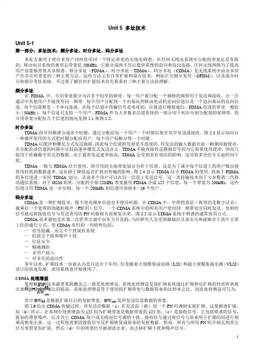
时分多址TDMA 将可用频谱分成多个时隙,通过分配给每一个用户一个时隙以便在其中发送或接收。
图5.3显示如何以一种循环复用的方式把时隙分配给用户,每个用户每帧分得一个时隙。
TDMA 以缓冲和爆发方式发送数据。
因此每个信道的发射是不连续的。
待发送的输入数据在前一帧期间被缓存,在分配给该信道的时隙中以较高速率爆发式发送出去。
TDMA 不能直接传送模拟信号因为它需要使用缓冲,因而只能用于传输数字形式的数据。
由于通常发送速率很高,TDMA 会受到多径效应的影响。
这导致多径信号引起码间干扰。
TDMA 一般与FDMA 结合使用,将可用的全部带宽划分为若干信道。
这是为了减少每个信道上的用户数以便使用较低的数据速率。
Unit 4 通信和信息论Unit 4-1第一部分:远程通信远程通信是远距离通信的信号传输,在现代,通常这个过程需要电子发射机发射电磁波,但是在早期远程通信包括使用烟火信号,鼓或旗语或日光仪。
今天,远程通信很普遍的,助推这一过程的设备如电视,无线电和电话在世界的许多地区都已很普遍。
还有连接这些设备的许多网络,包括计算机网络,公共电话网,无线电网和电视网络。
互联网上的计算机通信是众多通信的一个例子。
通信系统通常由通信工程师设计。
在这个领域中早期的发明家有Alexander Graham Bell, Guglielmo Marconi 和John Logie Baird。
通信在当今的世界经济发展中起着举足轻重的作用,通信产业的税收在世界总产值的比例已接近百分之三。
基本要素每个通信系统包括三个基本要素:采集信息并能将其转换为信号的发射机,传输信号的传输媒介,接收信号并能将其还原为有用信息的接收机。
考虑一个无线电广播的例子。
广播塔是发射机,收音机是接收机,传输媒介是自由空间。
通常通信系统都是双向的,一个设备既做发射机又做接收机,即收发器。
例如,移动手机就是一个收发器。
电话线上的通信称为点对点通信,因为只在一个发射机和一个接收机之间。
通过无线电广播的通信称为广播(一对多)通信,因为通信是在一个大功率的发射机和许多接收机之间。
模拟或数字信号可以是模拟的,也可以是数字的。
在模拟信号中,信号根据信息而连续变化。
在数字信号信息被编码为一组离散值(如,1和0)。
在传输过程中,模拟信号中的信息会因噪声而退化。
相反,只要噪声不超过一定的阈值,数字信号中的信息是不会丢失的。
这是数字信号相对于模拟信号一个关键的优点。
网络网络是由一个相互通信的发射机、接收机或收发机的集合。
数字网络由一个或多个路由器组成,路由器正确地将数据发送给用户。
模拟网路由一个或多个交换器组成,交换器在两个或多个用户间建立连接。
这两种网络都需要中继器,用于远距离传输时的放大或重建信号。
Unit 8 光通信Unit 8-1第一部分:电磁频谱仔细研究表8.1中的频率表可以看到各种用于信息传输的光学技术的潜力。
人们所感兴趣的“现代”常规通信系统的信息传播速率通常相应于电话系统中的音频、商用广播系统中的无线电频率、或是最先进的视频节目分配系统中的数字电视数据率。
这些数据率通常低于几个吉赫兹(GHz)。
如果传输这样的信息不是将它加载到光纤上,而是加载在略高于最大速率的射频载波上,则此射频载波就会是厘米波或是波长更长一些的波。
用光载波则有很大的优越性。
一个明显的优点就是光纤的低损耗和方向性。
载波的数据率显然必须高于信息速率。
通信系统的一个基本原则是频率愈高,技术就愈复杂。
处理微波就比处理无线电波更困难。
随着波长减小到接近于电路元件的尺寸,电路单元就不再是集总的,导线可起到反射元件以及(或)天线的作用,集总单元则成为电磁谐振器。
这通常意味着当发送的信息较多时,代价也较高,因此在较高的信息率要求较高的频率这层意义上,要考虑传输信息的每个bps的成本问题。
于是,观察上述频率表得到的第一个结论就是,对于频率为数百特赫兹(THz)的光载波而言,信息的带宽在某种意义上是免费的。
就是说与大多数器件相比,光的波长是如此之小,以至于所用技术与电和微波有根本的不同。
一旦我们具备了这样的技术,则无论信息率有多高,再也没有必要改变载波了,因为载波频率高于任何现实信息率所能达到的程度。
不过带宽也不是完全免费的,因为编码器和解码器必须工作在相应于信息率的频率上,而系统其余部分大都只需要处理载波和调制。
如果一个元件可以工作在5⨯1014Hz的频率上,在这个频率信息偏移千分之一(相应于500吉赫兹的信息率)对器件的性能将没有什么影响。
因此,只要系统已经建立起来,大体上就可以随意升级系统而不会涉及常规系统中改变电磁载波所需付出的那种代价。
光波的宽频带一个结果就是光载波可以同时携带许多不同电话信号和电视节目等。
通常实现这种同时传输多路信息的过程(至少以同步格式实现)称为时分复用。
电子信息工程专业常用词汇Aabbreviation n. 缩写accelerator n. 加速者,加速器accommodate v. 使适应,使调节accumulate v. 积聚, 堆积accumulator n. 累加器acquisition n. 获得,采集acquisition time 采集时间Activate a. 激活的active circuit 有源电路address line 地址线aforementioned a. 上述的,前述的algebra n.代数学alphanumeric a. 字母数字的alternating current 交流电流amber n.琥珀色analog n.模拟量analogous a.类似的,模拟的analog-to-digital converter(ADC)模数转换器analytical a. 分析的,解析的anode n. 阳极appropriate a. 合适的approximation n. 近似值assemblage n. 集合assembly language 汇编语言asymmetry n. 不对称attenuate v. 削弱,减弱,衰减attenuator n.衰减器Bband-gap energy 带隙能band-reject 带阻base n. 基极base 2 以2 为基数base-emitter current 基射电流bead n. 珠型bi-directional 双向的binary a. 二进位的bipolar a. 双极性的bipolar power 双极性电源block v. 阻塞Boolean n. 布尔Boolean algebra 布尔代数breadboard n.试验板breakdown voltage 击穿电压bridge arm 桥臂bridge circuit 桥路bulk n.大块,大批,体积;v. 越来越大,使更大Ccalibration n. 刻度calibration n.标度, 刻度, 校准canonical n. 牧师礼服,法服;a. 依教规的,权威的capacitance n.电容量cascade adj.级联的cathode n. 阴极Celsius a. 摄氏的Celsius a. 摄氏的channel n.通道characteristic n. 特性charge n. 电荷v.充电Choke v. 窒息,阻塞circuit n.电路circuitry n. 电路,线路cobalt n. 钴coefficients n. 系数collector n. 集电极common mode rejection ratio (CMRR) 共模抑制比common mode voltage 共模电压comparator n. 比较器compatible a.兼容的compensation n. 补偿, 赔偿complement n. 补充物compromise n.;v. 妥协,折中concession n. 让步,妥协conditioning n. 调节,调理conduct n.导体conduction band 传导带conductivity n. 传导性,传导率configuration n.配置constant n. 常数,恒量contiguous a. 邻近的,接近的control line 控制线control-oriented 控制方向conversion time 转换时间, 变换时间coulomb n. 库仑counter n. 计数器criterion n. 标准critical frequency 临界频率, 截止频率crocodile n. 鳄鱼cumbersome a. 麻烦的cumbersome a. 笨重的cursor n. 光标Cycle n. 循环, 周期Ddata line 数据线deactivate a. 非激活的decimal a. 十进位的, 小数的decimal a. 十进位的,小数的decode v. 解码,译解deduce v. 推论, 演绎出delicate a. 细致优雅的,微妙的,美味的deposit vt.存放, 堆积designate v. 指定desktop n. 桌面deterioration n. 恶化,退化dielectric n. 电介质dielectric strength 电介质强度, 绝缘强度differential amplifier 差动放大器differentiator n. 微分器diffuse v. 散播,使(光线)漫射digital a. 数字的digital-to-analog converter(DAC)数模转换器diode n.二极管direct current 直流电流disc n. 圆盘型discharge v.放电discrete adj.不连续的, 离散的dispatch v. 分发,派遣dissipate v. 使⋯⋯消散(浪费)divert v. 转移divide v. 分开,分类divider circuit 分压电路drift n. 漂流物, 漂流;v. 漂流Dual-Slope Ramp ADC 双积分ADCEelectrode n.电极electrolytic capacitor 电解电容electrolytic lead 电解铅electromotive a. 电的,电动的electromotive force 电势electron n. 电子emitter n. 发射极encapsulation n. 封装,包装encase v. 包围,装入箱内,把⋯⋯装入箱中,包起encode v. 编码entanglement n. 纠缠牵累epoxy n. 环氧基树脂equate vt. 等同,使相等equilibrium n. 平衡, 均衡erroneous a. 错误的,不正确的establish vt. 建立evaluate v. 评估,评价evolve v. 进展,进化execute v. 执行exemplify v. 例证,例示expansion slot 扩展槽exponential a.指数的exponential decay 指数式衰减Ffabricate v. 制造,装配factor n.因子Fahrenheit a. 华氏的;n. 华氏温度计farad n. 法拉feedback n.反馈ferrite n. 铁氧体filter n. 滤波器fine-tuning 调整finite open loop gain 有限开环增益first order system 一阶系统flowchart n.流程图fluctuation n. 波动,起伏flux line 磁通线follower n. 跟随器forward voltage 正向电压fraction n. 分数, 小部分, 破片fractional a.分数的full-duplex 全双工Ggalvanometer n.检流计gauge n. 标准度量,计量器generic a. 一般性的,标准样本应用程序Germanium n. 锗gyration n. 回旋,回转,旋转Hhardware n.硬件hard-wired 硬件线路Henry n. 亨,亨利hexadecimal n. 十六进制,十六进制的high-performance 高性能Hole n.空穴hysteresis 滞后作用,磁滞现象Iideal inverting amplifier 理想反向放大器impedance n. 阻抗impede v. 妨碍,阻碍,阻止impurity n. 杂质incandescent a. 白热的,发白热光的increment n.增量increment n. 增加(增加物,增量,余差) induce v.感应inductance n. 电感,感应系数inductor n.电感器inequality n. 不等式inevitably ad. 不可避免地infrared a. 红外线的initialization values 初始值initiate v. 开始,初始instantaneous a. 瞬间的,即刻的instrumentation amplifier 仪器放大器insulate v. 使⋯⋯绝缘,隔insulator n.绝缘体,绝热器integral n. 积分integrated circuit 集成电路integrator n.积分器interpret n.解释interrupt n. 中断interval n. 间隔inverter n. 变换器inverting input 反向输入isolation n. 隔离,孤立issue v. 发出Llatch v. 锁存lead compensation 导线补偿leakage n. 泄漏linkage n. 联系,连锁,结合logarithm n.对数loop n.循环lower-lying energy state 低电能态low-ripple source 低纹波源low-ripple 低纹波Mmacro a. 巨大的,突出的;n. 宏指令magnetic field 磁场magnitude n.大小, 数量mainline glue 主流程综述maneuver n. 演习,调遣,策略;v. 调遣,演习,用计策measurement junction 测量点megohm n.兆欧(姆)memory n. 存储器memory-read instruction 读存储器指令metallic a. 金属的microwave band 微波带宽microwave oven 微波炉millivolt n.毫伏misuse vt.&n. 误用,滥用mnemonic a. 助记的,记忆的modulo n. 模数;按模计算molecule n. 分子multimeter n. 万用表multiplexer n.多路器multiplication n. 乘法,增加Multiply v.乘, 增加multivibrator n. 多谐振荡器Nnegligible a. 可以忽略的, 微不足道的nibble n. 轻咬,啃;v. 咬,一点点地咬,慢慢啃nickel n.镍nonideal adj.非理想的noninverting input 同向输入nonlinear a. 非线性的non-page-oriented 面向非页面的nonsymmetrical a. 不对称的nonvolatile a. 永久的,长存的,不挥发的,非挥发性的notch filter 槽型滤波器null n.零, 空numerator n.分子Oobsolete a. 已废弃的,过时的obstacle n. 障碍octal a.八进制的offset n. 偏移offset current 偏移电流ohm n.欧姆omega n. 希腊字母的最后一个字Ωopcode(operand code) 操作码open-collector 集电极开路operational amplifier 运算放大器optimize v. 使⋯⋯完美,使⋯⋯完善;v.优化overlap n.(数)交迭,相交Pparallel a. 并行的parity n. 同等,同格,同位passive band-pass filter 无源带通滤波器pedestrian n.行人Peltier effect 珀耳帖效应peripheral a.外设的, n. 外设peripheral a.外围的peruse v. 熟读,精读,阅读pictorial a. 绘画的n. 画报pinout 管脚引出platinum n. 白金plumb n. 测水锤,垂直;a. 垂直的;v. 探测,了解pointless a.无意义的polarise vt. 极化polyester n.聚酯polystyrene n. 聚苯乙烯potential n.电位,电势potential drop 电位降,势能落差precautions n. 预防,保护prefix n. 前缀prescaler n. 预换算装置,预定标器printed circuit board 印制电路板procedure n. 程序,步骤processor 处理器program n. 编程,程序Program Status Word(PSW) 程序状态字prolong v. 延长,拖延propagation n. 增殖,繁殖,传播proportionately ad. 相称地,成比例地pull-up 上拉Qquadrature n.正交,九十度相位差quote n. 引用;v. 引述, 举证, 报价Rradial a. 光线的,光线状的,放射状的ramp voltage 斜坡电压range n.幅度, 范围ratings n. 额定值capacitor [k__p_sit_] n.电容器recipient n. 接受者rectangular wave 矩形波rectifier diode 整流二极管reference n. 参考reference junction 参考点register n. 寄存器relay n. 继电器reliability n. 可靠性remedial a. 治疗的,补救的,矫正的repeatable a. 可重复的reposition n. 新位置;v. 改变⋯⋯的位置resistance coefficient 电阻系数resistive a. 电阻的resistor n.电阻restrict v.限制reverse voltage 反向电压rising (or falling) edge 上升(下降)沿rod n. 棒型rudimentary a. 基本的,初步的,起码的,根本的Ssample-and-hold 采样保持saturate vt.使饱和scheme n. 方案,蓝图,框架Seebeck effect 塞贝克效应self-nulling 自回零semiconductor n. 半导体semiconductor n. 半导体sensitivity n. 灵敏度sequence n. 序列,顺序sequential a. 连续的shaft n.轴sheath n. 鞘,叶鞘, 翅鞘shorthand n.速记shunt vt. 分流(器)siblings n. 兄弟signal diode 信号二极管silicon n. 硅sinusoidal a. 正弦曲线的slope n.斜率Socket n. 插座software n.软件soldering n. 焊接,锡焊,低温焊接span n. 跨距square wave 方波Stack Pointer (SP) 堆栈指针stipulate v.规定stipulation n. 约束,约定,规定strobe n. 闸门(频闪观测器,频闪放电管);v. 闸(选通,发出选通脉冲)stuff n. 材料,原料,东西;v. 填满,塞满subroutine n. 子程序subscript n.下标,标记Successive Approximation ADC 逐次逼近ADCsuffix n. 后缀superimpose vt. 重叠(安装, 添加)supplier n. 供应商Ttally n. 标签(手执计数器,对应物);v. 计算(记录) tantalum n.钽(金属元素)Teflon n. 聚四氟乙烯theoretical a. 理论上的thermal a. 热的,热量的thermal a. 热的,热量的thermistor n. 热敏电阻thermocouple n. 热电偶thermoelectric a. 热电的thermometer n. 温度计thermostat n. 恒温器thermostatic a. 温度调节装置的Thévenin equivalent circuit 戴维南等效电路timer n. 计时器,定时器tolerance n.容限,公差,允许误差traffic table 切换表;交通图transient response 暂态响应transistor n. 晶体管transparent a. 可为某种射线所透射的,透明的trigger n.触发器trimmer adj. 可变的tri-state buffer 三态缓冲器truncate v. 截去tube n.电子管tune v. 调谐twin-T filter 双T 滤波器twist n. 扭曲;v. 拧,扭曲Uultraviolet-Erasable 紫外线可擦除的uncertainty n. 不确定unidirectional n.单向性的unipolar a. 单极性的USART (Universal Serial Asynchronous Receiver & Transmitter)通用串行异步收发器VVacuum n. 真空,空间,真空吸尘器valence n. 化合价valence band 价(电子)带valence band 价(电子)带valence electron 价电子valve n.阀variation n. 变化, 变动versus n.对抗vibrate v. (使)振动,(使)摇摆;摇动,震动vibration n. 震动,颤动voltage detector 电压侦测器voltage follower 电压跟随器voltage regulator 稳压器,电压调节器WWheatstone bridge 惠斯登电桥Zzener diode 稳压二极管,齐纳二极管zener voltage 齐纳电压zeroing n. 零位调整电子信息工程专业常用词组Aabbreviated dialing 快速呼叫,缩位拨号acquisition time 采集时间active circuit 有源电路address space 地址空间alternating current 交流电流amplitude modulation 调幅,波幅调制anti-alias 抗锯齿,平滑API(Application Programming Interface)应用编程接口assembly language 汇编语言automatic call re-routing 自动呼叫转移BBackward and Binary Compatibility向后二进制方式兼容backward compatibility 向后兼容;反向兼容性band-gap energy 带隙能band-reject 带阻bi-directional 双向的bi-directional 双向的bipolar power 双极性电源biquad (a stage containing two poles and up to two zeros)两象限bluetooth 蓝牙技术board-level assemblies 板级装配bottleneck 瓶颈breakdown voltage 击穿电压bridge arm 桥臂bridge circuit 桥路Ccarrier wave 载波cellular telephone 移动电话circuit switched 电路切换co-axial cable 同轴电缆coaxial cables 同轴电缆common mode rejection ratio (CMRR) 共模抑制比common mode voltage 共模电压conduction band 传导带connection-oriented 面向连接的control-oriented 控制方向conversion time 转换时间, 变换时间critical frequency 临界频率, 截止频率critical region 临界代码段Ddetailed billing 详细话单dielectric strength 电介质强度, 绝缘强度differential amplifier 差动放大器direct current 直流电流divider circuit 分压电路Eelectrical impulse 电磁脉冲,电脉冲electrolytic capacitor 电解电容electrolytic lead 电解铅electromagnetic energy 电磁能electromotive force 电势embedded system 嵌入式系统executable code 可执行代码expansion slot 扩展槽exponential decay 指数式衰减FFeature compatibility 特征兼容性fiber optic cable 光导纤维电缆fibre optic cable 光缆;光纤电缆FIFO(First-In First-Out)先入先出file system 文件系统finite open loop gain 有限开环增益first order system 一阶系统fixed-point 定点flip-flop 触发器floating point operation 浮点操作,浮点运算floating-point 浮点floppy disk 柔性塑料磁盘,(软)塑料磁盘,软盘flux line 磁通线forward voltage 正向电压Fourier Transform 傅立叶变换frequency modulation 调频FTP(File Transfer Protocol)文件传输协议full-duplex 全双工fundamental frequency 基波频率Ggeneral-purpose 通用的GPRS (General Packet Radio Service) 通用分组无线业务Hhard-wired 硬件线路hifi (High Fidelity) 高保真度high level programming language 高级编程语言high-fidelity 高保真high-performance 高性能HTTP(Hypertext Transfer Protocol)WWW 服务程序所用的协议Iideal inverting amplifier 理想反向放大器initialization values 初始值instantaneous power consumptions 瞬时功率耗散instrumentation amplifier 仪器放大器integrated circuit 集成电路interface equipment 接口设备interprocess communication 进程间通信interrupt-off 中断隔离inverting input 反向输入Llead compensation 导线补偿linux 一种可免费使用的UNIX 操作系统,运行于普通PC 机上little-endian 小端模式lower-lying energy state 低电能态Mmagnetic field 磁场measurement junction 测量点memory access 存储器存取memory mapping 存储器映射microwave band 微波带宽microwave oven 微波炉MIPS(Million Instructions Per Second)每秒百万条指令MMU(Memory Management Unit)存储器管理单元monopole antenna 磁单极子,单极天线Moore‟s law 摩尔定律Nnoninverting input 同向输入non-page-oriented 面向非页面的notch filter 槽型滤波器numerically-intensive 高强度数字运算Oobject code 目标代码OEM(Original Equipment Manufacturer)初始设备制造厂家offset current 偏移电流opcode(operand code) 操作码operating system 操作系统operational amplifier 运算放大器optical fiber 光缆OS compatibility 操作系统兼容性Ppacket switched 包交换paging system 分页系统parallel communication 并行通信passive band-pass filter 无源带通滤波器PDA (Personal Digital Assistant)个人数字助理Peltier effect 珀耳帖效应phase modulation 调相, 相位调制pinout 管脚引出pocket PC 与Palm 齐名的掌上电脑平台point-of-sale 销售点系统potential drop 电位降,势能落差power consumption 功耗,消耗Power PC IBM 和Apple 公司联合生产的个人台式机PPP(Peer.Peer Protocol)端对端协议printed circuit board 印制电路板Program Status Word(PSW) 程序状态字Rramp voltage 斜坡电压rectifier diode 整流二极管reference junction 参考点resistance coefficient 电阻系数reverse voltage 反向电压RF connector 射频连接器ROM(read only memory)只读存储器round-off 舍入round-robin scheduling 轮式调度;循环调度RTOS(Real-Time Operating System)实时操作系统rule of thumb 经验法则SSeebeck effect 塞贝克效应seismic vibrations 地震颤动self-nulling 自回零serial communication 串行通信signal diode 信号二极管single precision floating point 单精度浮点数source code 源代码Source compatibility 源代码兼容性spinlock 旋转锁spread-sheet 总分析表,棋盘式对照表Stack Pointer (SP) 堆栈指针Ttear down 拆除,拆毁Thévenin equivalent circuit 戴维南等效电路Tool compatibility 开发工具兼容性trade-off 权衡(折中,换位,比较评定,放弃,交换) traffic table 切换表;交通图transient response 暂态响应troubleshooting 发现并修理故障,解决纷争twin-T filter 双T 滤波器Uultraviolet-Erasable 紫外线可擦除的USART (Universal Serial Asynchronous Receiver & Transmitter)通用串行异步收发器Vvalence band 价(电子)带valence band 价(电子)带valence electron 价电子virtual memory 虚拟内存voltage detector 电压侦测器voltage follower 电压跟随器voltage regulator 稳压器,电压调节器WWheatstone bridge 惠斯登电桥Zzener diode 稳压二极管,齐纳二极管zener voltage 齐纳电压专业术语常用名词缩写中英文对照表AA:Antenna amplifier 开线放大器AA:Architectural Acoustics建筑声学AC:Analogue Controller 模拟控制器ACD:Automatic Call Distribution 自动分配话务ACS:Access Control System出入控制系统AD:Addressable Detector地址探测器ADM:Add/Drop Multiplexer分插复用器ADPCM:Adaptive Differential ulse Code Modulation 自适应差分脉冲编码调制置AWG:American Wire Gauge美国线缆规格BAC:Building Automation & Control net建筑物自动化和控制网络BAM:Background Administration Module后管理模块BBER:Background Block Error Ratio背景块误码比BCC:B-channel Connect ControlB通路连接控制BD:Building DistributorBEF:Buiding Entrance Facilities 建筑物入口设施BFOC:Bayonet Fibre Optic Connector大口式光纤连接器BUL:Back up lighting备用照明C:Container 容器CA:Call Accounting电话自动计费系统CATV:Cable Television 有线电视CC:Call Control 呼叫控制CC:Coax cable 同轴电缆CCD:Charge coupled devices 电荷耦合器件CCF:Cluster Contril Function 簇控制功能CD:Campus Distributor 建筑群配线架CD:Combination detector 感温,感烟复合探测器CDCA:Continuous Dynamic Channel Assign 连续的动态信道分配CDDI:Copper Distributed Data 合同缆分布式数据接口CDES:Carbon dioxide extinguisbing system 二氧化碳系统CDMA:Code Division Multiplex Access 码分多址CF:Core Function 核心功能CFM:Compounded Frequency Modulation 压扩调频繁CIS:Call Information System 呼叫信息系统CISPR:Internation Special Conmittee On Radio Interference 国际无线电干扰专门委员会CLNP:Connectionless Network Protocol 无连接模式网络层协议CLP:Cell Loss Priority信元丢失优先权CM:Communication Module 通信模块CM:Configuration Management 配置管理CM:Cross-connect Matrix交叉连接矩阵CMI:Coded Mark Inversion传号反转码CMISE:Common Management Information Service公用管理信息协议服务单元CPE:Convergence protocol entity 会聚协议实体CR/E:card reader /Encoder (Ticket reader )卡读写器/编码器CRC:Cyclic Redundancy Check 循环冗佘校验CRT:Cathode Ray Tabe 显示器,监视器,阴极射线管CS: Convergence service 会聚服务CS:Cableron Spectrum 旧纳档块化技术CS:Ceiling Screen 挡烟垂壁CS:Convergence Sublayer合聚子层CSC:Combined Speaker Cabinet 组合音响CSCW:Computer supported collaborative work 计算机支持的协同工作CSES:Continuius Severely Errored Second 连续严重误码秒CSF:Cell Site Function 单基站功能控制CTB:Composite Triple Beat 复合三价差拍CTD:Cable Thermal Detector 缆式线型感温探测器CTNR:carrier to noise ratio 载波比CW:Control Word 控制字D:Distortion 失真度D:Distributive 分布式DA:Distribution Amplifier 分配的大器DBA:Database Administrator数据库管理者DBCSN:Database Control System Nucleus数据库控制系统核心DBOS:Database Organizing System 数据库组织系统DBSS:Database Security System 数据库安全系统DC:Door Contacts大门传感器DCC:Digital Communication Channel数字通信通路DCN:Data Communication Network 数据通信网DCP-I:Distributed Control Panel -Intelligent智能型分散控制器DCS:Distributed Control System集散型控制系统DDN:Digital Data Network 数字数据网DDS:Direct Dignital Controller直接数字控制器DDW:Data Describing Word 数据描述字DECT:Digital Enhanced Cordless Telecommunication增强数字无绳通讯DFB:Distributed Feedback 分布反馈DID:Direct Inward Dialing 直接中继方式,呼入直拨到分机用户DLC:Data Link Control Layer 数据链路层DLI:DECT Line InterfaceDODI:Direct Outward Dialing One 一次拨号音DPH:DECT PhoneDRC:Directional Response Cahracteristics 指向性响应DS:Direct Sound 直正声DSP:Digital signal Processing 数字信号处理DSS:Deiision Support System 决策支持系统DTMF:Dual Tone Multi-Frequency 双音多频DTS:Dual -Technology Sensor 双鉴传感器DWDM:Dense Wave-length Division Multiplexing 密集波分复用DXC:Digital Cross-Connect 数字交叉连接E:Expander 扩展器EA-DFB:Electricity Absorb-Distributed Feedback 电吸收分布反馈ECC:Embedded Control Channel 嵌入或控制通道EDFA:Erbium-Doped Fiber Amplifier掺饵光纤放大器EDI:Electronic Data Interexchange 电子数据交换EIC:Electrical Impedance Characteristics 电阻抗特性EMC:Electro Magnetic Compatibiloty 电磁兼容性EMI:Electro Magnetic Interference 电磁干扰EMS:Electromagnetic Sensitibility 电磁敏感性EN:Equivalent Noise 等效噪声EP:Emergency Power 应急电源ES:Emergency Sooket 应急插座ES:Evacuation Sigvial疏散照明ESA:Error SecondA 误码秒类型AESB:ErrorSecondB 误码秒类型BESD:Electrostatic Discharge静电放电ESR:Errored Second Ratio 误码秒比率ETDM:Electrical Time Division Multiplexing电时分复用ETSI:European Telecommunication Standards Institute 欧洲电信标准协会FAB:Fire Alarm Bell 火警警铃FACU:Fire Alarm Contrlol Unit 火灾自动报警控制装置FC:Failure Count 失效次数FC:Frequency Converter 频率变换器FCC:Fire Alarm System 火灾报警系统FCS:Field Control System 现场总线FCU:Favn Coil Unit风机盘管FD:Fire Door 防火门FD:Flame Detector 火焰探测器FD:Floor DistributorFD:Frequency Dirsder 分频器FDD:Frequency Division Dual 频分双工FDDI:Fiberdistributed Data Interface光纤缆分布式数据接口。
电子信息工程专业英语教程第三版译者:唐亦林p32In 1945 H. W. Bode presented a system for analyzing the stability of feedback systems by using graphical methods. Until this time, feedback analysis was done by multiplication and division, so calculation of transfer functions was a time consuming and laborious task. Remember, engineers did not have calculators or computers until the '70s. Bode presented a log technique that transformed the intensely mathematical process of calculating a feedback system's stability into graphical analysis that was simple and perceptive. Feedback system design was still complicated, but it no longer was an art dominated by a few electrical engineers kept in a small dark room. Any electrical engineer could use Bode's methods find the stability of a feedback circuit, so the application of feedback to machines began to grow. There really wasn't much call for electronic feedback design until computers and transducers become of age.1945年HW伯德提出了一套系统方法,用图形化方法来分析反馈系统的稳定性。
电子信息工程专业英语词典电子信息工程专业常用词汇Aabbreviation n. 缩写accelerator n. 加速者,加速器 accommodate v. 使适应,使调节 accumulate v. 积聚, 堆积 accumulator n. 累加器 acquisition n. 获得,采集 acquisition time 采集时间 Activate a. 激活的 active circuit 有源电路 address line 地址线aforementioned a. 上述的,前述的 algebra n.代数学alphanumeric a. 字母数字的 alternating current 交流电流 amber n.琥珀色analog n.模拟量analogous a.类似的,模拟的analog-to-digital converter(ADC)模数转换器analytical a. 分析的,解析的anode n. 阳极appropriate a. 合适的 approximation n. 近似值 assemblage n. 集合assembly language 汇编语言 asymmetry n. 不对称attenuate v. 削弱,减弱,衰减 attenuator n.衰减器Bband-gap energy 带隙能 band-reject 带阻 base n. 基极 base 2 以2 为基数base-emitter current 基射电流 bead n. 珠型bi-directional 双向的 binary a. 二进位的 bipolar a. 双极性的 bipolar power 双极性电源 block v. 阻塞 Boolean n. 布尔Boolean algebra 布尔代数breadboard n.试验板breakdown voltage 击穿电压 bridge arm 桥臂 bridge circuit 桥路bulk n.大块,大批,体积;v. 越来越大,使更大Ccalibration n. 刻度calibration n.标度, 刻度, 校准canonical n. 牧师礼服,法服;a. 依教规的,权威的capacitance n.电容量 cascade adj.级联的 cathode n. 阴极 Celsius a. 摄氏的 Celsius a. 摄氏的 channel n.通道characteristic n. 特性 charge n. 电荷v.充电 Choke v. 窒息,阻塞 circuit n.电路circuitry n. 电路,线路 cobalt n. 钴coefficients n. 系数 collector n. 集电极common mode rejection ratio (CMRR) 共模抑制比 common mode voltage 共模电压comparator n. 比较器 compatible a.兼容的compensation n. 补偿, 赔偿 complement n. 补充物compromise n.;v. 妥协,折中 concession n. 让步,妥协 conditioning n.调节,调理 conduct n.导体conduction band 传导带conductivity n. 传导性,传导率 configuration n.配置 constant n. 常数,恒量contiguous a. 邻近的,接近的 control line 控制线control-oriented 控制方向conversion time 转换时间, 变换时间 coulomb n. 库仑 counter n. 计数器criterion n. 标准critical frequency 临界频率, 截止频率 crocodile n. 鳄鱼cumbersome a. 麻烦的 cumbersome a. 笨重的 cursor n. 光标Cycle n. 循环, 周期Ddata line 数据线deactivate a. 非激活的decimal a. 十进位的, 小数的 decimal a. 十进位的,小数的 decode v. 解码,译解 deduce v. 推论, 演绎出delicate a. 细致优雅的,微妙的,美味的 deposit vt.存放, 堆积 designate v. 指定 desktop n. 桌面deterioration n. 恶化,退化 dielectric n. 电介质dielectric strength 电介质强度, 绝缘强度 differential amplifier 差动放大器differentiator n. 微分器diffuse v. 散播,使(光线)漫射 digital a. 数字的digital-to-analog converter(DAC)数模转换器diode n.二极管direct current 直流电流 disc n. 圆盘型 discharge v.放电discrete adj.不连续的, 离散的 dispatch v. 分发,派遣dissipate v. 使??消散(浪费) divert v. 转移divide v. 分开,分类 divider circuit 分压电路drift n. 漂流物, 漂流;v. 漂流 Dual-Slope Ramp ADC 双积分ADCEelectrode n.电极electrolytic capacitor 电解电容 electrolytic lead 电解铅electromotive a. 电的,电动的 electromotive force 电势electron n. 电子 emitter n. 发射极encapsulation n. 封装,包装encase v. 包围,装入箱内,把??装入箱中,包起 encode v. 编码entanglement n. 纠缠牵累 epoxy n. 环氧基树脂 equate vt. 等同,使相等equilibrium n. 平衡, 均衡erroneous a. 错误的,不正确的 establish vt. 建立evaluate v. 评估,评价 evolve v. 进展,进化 execute v. 执行exemplify v. 例证,例示 expansion slot 扩展槽 exponential a.指数的exponential decay 指数式衰减Ffabricate v. 制造,装配 factor n.因子Fahrenheit a. 华氏的;n. 华氏温度计 farad n. 法拉 feedback n.反馈ferrite n. 铁氧体 filter n. 滤波器 fine-tuning 调整finite open loop gain 有限开环增益 first order system 一阶系统 flowchart n.流程图fluctuation n. 波动,起伏 flux line 磁通线 follower n. 跟随器forward voltage 正向电压fraction n. 分数, 小部分, 破片 fractional a.分数的 full-duplex 全双工Ggalvanometer n.检流计gauge n. 标准度量,计量器generic a. 一般性的,标准样本应用程序 Germanium n. 锗gyration n. 回旋,回转,旋转Hhardware n.硬件 hard-wired 硬件线路 Henry n. 亨,亨利hexadecimal n. 十六进制,十六进制的 high-performance 高性能 Hole n.空穴hysteresis 滞后作用,磁滞现象 low-ripple source 低纹波源low-ripple 低纹波Mmacro a. 巨大的,突出的;n. 宏指令 magnetic field 磁场magnitude n.大小, 数量 mainline glue 主流程综述Iideal inverting amplifier 理想反向放大器 impedance n. 阻抗impede v. 妨碍,阻碍,阻止 impurity n. 杂质incandescent a. 白热的,发白热光的 increment n.增量increment n. 增加(增加物,增量,余差) induce v.感应inductance n. 电感,感应系数 inductor n.电感器 inequality n. 不等式inevitably ad. 不可避免地 infrared a. 红外线的 initialization values 初始值 initiate v. 开始,初始instantaneous a. 瞬间的,即刻的 instrumentation amplifier 仪器放大器insulate v. 使??绝缘,隔insulator n.绝缘体,绝热器 integral n. 积分integrated circuit 集成电路 integrator n.积分器 interpret n.解释interrupt n. 中断 interval n. 间隔 inverter n. 变换器 inverting input 反向输入 isolation n. 隔离,孤立 issue v. 发出Llatch v. 锁存lead compensation 导线补偿 leakage n. 泄漏linkage n. 联系,连锁,结合 logarithm n.对数 loop n.循环lower-lying energy state 低电能态maneuver n. 演习,调遣,策略;v. 调遣,演习,用计策measurement junction 测量点 megohm n.兆欧(姆) memory n. 存储器memory-read instruction 读存储器指令 metallic a. 金属的microwave band 微波带宽 microwave oven 微波炉 millivolt n.毫伏misuse vt.& n. 误用,滥用mnemonic a. 助记的,记忆的 modulo n. 模数;按模计算 molecule n. 分子multimeter n. 万用表 multiplexer n.多路器multiplication n. 乘法,增加 Multiply v.乘, 增加multivibrator n. 多谐振荡器N negligible a. 可以忽略的, 微不足道的nibble n. 轻咬,啃;v. 咬,一点点地咬,慢慢啃 nickel n.镍nonideal adj.非理想的noninverting input 同向输入 nonlinear a. 非线性的non-page-oriented 面向非页面的 nonsymmetrical a. 不对称的nonvolatile a. 永久的,长存的,不挥发的,非挥发性的notch filter 槽型滤波器 null n.零, 空numerator n.分子Oobsolete a. 已废弃的,过时的 obstacle n. 障碍 octal a.八进制的offset n. 偏移offset current 偏移电流 ohm n.欧姆omega n. 希腊字母的最后一个字Ω opcode(operand code) 操作码 open-collector 集电极开路operational amplifier 运算放大器optimize v. 使??完美,使??完善;v.优化 overlap n.(数)交迭,相交Pparallel a. 并行的parity n. 同等,同格,同位passive band-pass filter 无源带通滤波器 pedestrian n.行人Peltier effect 珀耳帖效应 peripheral a.外设的, n. 外设 peripheral a.外围的peruse v. 熟读,精读,阅读 pictorial a. 绘画的n. 画报 pinout 管脚引出platinum n. 白金plumb n. 测水锤,垂直;a. 垂直的;v. 探测,了解pointless a.无意义的 polarise vt. 极化 polyester n.聚酯polystyrene n. 聚苯乙烯 potential n.电位,电势potential drop 电位降,势能落差 precautions n. 预防,保护 prefix n. 前缀prescaler n. 预换算装置,预定标器 printed circuit board 印制电路板procedure n. 程序,步骤 processor 处理器program n. 编程,程序Program Status Word(PSW) 程序状态字 prolong v. 延长,拖延propagation n. 增殖,繁殖,传播 proportionately ad. 相称地,成比例地pull-up 上拉Qquadrature n.正交,九十度相位差 quote n. 引用;v. 引述, 举证, 报价Rradial a. 光线的,光线状的,放射状的 ramp voltage 斜坡电压 range n.幅度, 范围ratings n. 额定值capacitor [k__p_sit_] n.电容器 recipient n. 接受者rectangular wave 矩形波 rectifier diode 整流二极管 reference n. 参考reference junction 参考点 register n. 寄存器 relay n. 继电器reliability n. 可靠性remedial a. 治疗的,补救的,矫正的 repeatable a. 可重复的reposition n. 新位置;v. 改变??的位置 resistance coefficient 电阻系数resistive a. 电阻的 resistor n.电阻 restrict v.限制reverse voltage 反向电压rising (or falling) edge 上升(下降)沿 rod n. 棒型rudimentary a. 基本的,初步的,起码的,根本的Ssample-and-hold 采样保持 saturate vt.使饱和scheme n. 方案,蓝图,框架 Seebeck effect 塞贝克效应 self-nulling 自回零semiconductor n. 半导体 semiconductor n. 半导体 sensitivity n. 灵敏度 sequence n. 序列,顺序 sequential a. 连续的 shaft n.轴sheath n. 鞘,叶鞘, 翅鞘 shorthand n.速记 shunt vt. 分流(器)siblings n. 兄弟signal diode 信号二极管 silicon n. 硅sinusoidal a. 正弦曲线的slope n.斜率 Socket n. 插座 software n.软件soldering n. 焊接,锡焊,低温焊接 span n. 跨距 square wave 方波Stack Pointer (SP) 堆栈指针 stipulate v.规定stipulation n. 约束,约定,规定strobe n. 闸门(频闪观测器,频闪放电管);v. 闸(选通,发出选通脉冲)stuff n. 材料,原料,东西;v. 填满,塞满 subroutine n. 子程序subscript n.下标,标记Successive Approximation ADC 逐次逼近ADC suffix n. 后缀superimpose vt. 重叠(安装, 添加) supplier n. 供应商Ttally n. 标签(手执计数器,对应物);v. 计算(记录) tantalum n.钽(金属元素) Teflon n. 聚四氟乙烯 theoretical a. 理论上的 thermal a. 热的,热量的 thermal a. 热的,热量的 thermistor n. 热敏电阻 thermocouple n. 热电偶 thermoelectric a. 热电的 thermometer n. 温度计 thermostat n. 恒温器thermostatic a. 温度调节装置的Thévenin equivalent circuit 戴维南等效电路 timer n. 计时器,定时器tolerance n.容限,公差,允许误差 traffic table 切换表;交通图 transient response 暂态响应 transistor n. 晶体管transparent a. 可为某种射线所透射的,透明的 trigger n.触发器 trimmer adj. 可变的 tri-state buffer 三态缓冲器 truncate v. 截去 tube n.电子管tune v. 调谐twin-T filter 双T 滤波器twist n. 扭曲;v. 拧,扭曲Uultraviolet-Erasable 紫外线可擦除的 uncertainty n. 不确定 unidirectional n.单向性的 unipolar a. 单极性的USART (Universal Serial Asynchronous Receiver & Transmitter)通用串行异步收发器VVacuum n. 真空,空间,真空吸尘器 valence n. 化合价 valence band 价(电子)带 valence band 价(电子)带 valence electron 价电子 valve n.阀variation n. 变化, 变动 versus n.对抗vibrate v. (使)振动,(使)摇摆;摇动,震动 vibration n. 震动,颤动voltage detector 电压侦测器 voltage follower 电压跟随器voltage regulator 稳压器,电压调节器WWheatstone bridge 惠斯登电桥Zzener diode 稳压二极管,齐纳二极管 zener voltage 齐纳电压 zeroing n. 零位调整感谢您的阅读,祝您生活愉快。
电子信息工程专业英语词汇精华版公司标准化编码 [QQX96QT-XQQB89Q8-NQQJ6Q8-MQM9N]transistor n 晶体管diode n 二极管semiconductor n 半导体resistor n 电阻器capacitor n 电容器alternating adj 交互的amplifier n 扩音器,放大器integrated circuit 集成电路linear time invariant systems 线性时不变系统voltage n 电压,伏特数tolerance n 公差;宽容;容忍condenser n 电容器;冷凝器dielectric n 绝缘体;电解质electromagnetic adj电磁的adj 非传导性的deflection n偏斜;偏转;偏差linear device 线性器件the insulationresistance 绝缘电阻anode n 阳极,正极cathode n阴极breakdown n 故障;崩溃terminal n终点站;终端,接线端emitter n 发射器collect v收集,集聚,集中insulator n 绝缘体,绝热器oscilloscope n示波镜;示波器gain n 增益,放大倍数forward biased 正向偏置reverse biased 反向偏置P-N junction PN结MOS(metal-oxidesemiconductor)金属氧化物半导体enhancement andexhausted 增强型和耗尽型integrated circuits集成电路analog n 模拟digital adj 数字的,数位的horizontal adj, 水平的,地平线的vertical adj 垂直的,顶点的amplitude n 振幅,广阔,丰富attenuation n衰减;变薄;稀薄化multimeter n 万用表frequency n 频率,周率the cathode-ray tube 阴极射线管dual-trace oscilloscope 双踪示波器signal generatingdevice 信号发生器peak-to-peak output voltage 输出电压峰峰值sine wave 正弦波triangle wave 三角波square wave 方波amplifier 放大器,扩音器oscillator n 振荡器feedback n 反馈,回应phase n 相,阶段,状态filter n 滤波器,过滤器rectifier n整流器;纠正者band-stop filter带阻滤波器band-pass filter 带通滤波器decimal adj 十进制的,小数的hexadecimal adj/n十六进制的binary adj 二进制的;二元的octal adj 八进制的domain n 域;领域code n代码,密码,编码v编码the Fourier transform傅里叶变换Fast Fourier Transform快速傅里叶变换microcontroller n 微处理器;微控制器assembly languageinstrucions n 汇编语言指令chip n 芯片,碎片modular adj 模块化的;模数的sensor n 传感器plug vt堵,塞,插上n 塞子,插头,插销coaxial adj 同轴的,共轴的fiber n 光纤relay contact 继电接触器single instruction programmer 单指令编程器dedicated manufactures programming unit 专供制造厂用的编程单元beam n (光线的)束,柱,梁polarize v(使)偏振,(使)极化Cathode Ray Tube(CRT)阴极射线管neuron n神经元;神经细胞fuzzy adj 模糊的Artificial IntelligenceShell 人工智能外壳程序Expert Systems 专家系统Artificial Intelligence人工智能Perceptive Systems 感知系统neural network 神经网络fuzzy logic 模糊逻辑intelligent agent 智能代理electromagnetic adj电磁的coaxial adj 同轴的,共轴的microwave n 微波charge v充电,使充电insulator n 绝缘体,绝缘物nonconductive adj非导体的,绝缘的antenna n天线;触角modeling n建模,造型simulation n 仿真;模拟prototype n 原型array n 排队,编队vector n 向量,矢量wavelet n 微波,小浪sine 正弦 cosine余弦inverse adj倒转的,反转的n反面;相反v倒转high-performance 高精确性,高性能two-dimensional 二维的;缺乏深度的three-dimensional 三维的;立体的;真实的object-oriented programming面向对象的程序设计spectral adj 光谱的attenuation n衰减;变薄;稀释distortion n 失真,扭曲,变形wavelength n 波长refractive adj 折射的ATM 异步传输模式Asynchronous Transfer ModeADSL非对称用户数字线Asymmetric digital subscriber lineVDSL甚高速数字用户线very high data rate digital subscriber lineHDSL高速数据用户线 high rate digital subscriber line FDMA频分多址(FrequencyDivision MultipleAccess)TDMA时分多址(TimeDivision MultipleAccess)CDMA同步码分多址方式(Code Division MultipleAccess)WCDMA宽带码分多址移动通信系统(Wideband CodeDivision MultipleAccess)TD-SCDMA(Time DivisionSynchronous CodeDivision MultipleAccess)时分同步码分多址SDLC(synchronous datalink control)同步数据链路控制HDLC(high-level datalink control)高级数据链路控制IP/TCP(internetprotocol /transferControl Protocol)网络传输控制协议ITU (InternationalTelecommunication Union)国际电信联盟ISO国际标准化组织(InternationalStandardizationOrganization);OSI开放式系统互联参考模型(Open SystemInterconnect)GSM全球移动通信系统(Global System forMobile Communications)GPRS通用分组无线业务(General Packet RadioService)FDD(frequency divisionduplex)频分双工TDD(time divisionduplex)时分双工VPI虚路径标识符(Virtual PathIdentifier);ISDN(Integrated Services Digital Network)综合业务数字网IDN综合数字网(integrated digital network)HDTV (high definition television)高清晰度电视DCT(Discrete Cosine Transform)离散余弦变换VCI(virtual circuit address)虚通路标识MAN城域网Metropolitan area networksLAN局域网local area networkWAN广域网wide area network同步时分复用STDM Synchronous Time Division Multiplexing统计时分复用STDM Statistical Time Division Multiplexing 单工传输simplextransmission半双工传输half-duplextransmission全双工传输full-duplextransmission交换矩阵SwitchingMatrix电路交换 circuitswitching分组交换packetswitching报文交换messageswitching奇偶校验parity checking循环冗余校验CRC CyclicRedundancy Check虚过滤Virtual filter数字滤波digitalfiltering伪随机比特Quasi RandomBit带宽分配 Bandwidthallocation信源information source信宿destination数字化digitalize数字传输技术Digitaltransmission technology灰度图像Grey scaleimages灰度级Grey scale level幅度谱Magnitudespectrum相位谱Phase spectrum频谱frequency spectrum智能设备Smart Device软切换Soft handover硬切换 Hard Handover相干检测Coherentdetection边缘检测Edge detection冲突检测collision detection业务集合service integration业务分离/综合service separation/ integration网络集合network integration环形网Ring networks令牌环网Token Ring network网络终端Network Terminal用户终端user terminal用户电路line circuit电路利用率channel utilization(通道利用率)相关性coherence相干解调coherent demodulation数字图像压缩digital image compression 图像编码image encoding有损/无损压缩lossy/losslesscompression解压decompression呼叫控制Call Control误差控制error control存储程序控制storedprogram control存储转发方式store-and-forward manner语音\视频传输voice\videotransmission视频点播video-on-demand(VOD)会议电视VideoConference有线电视cabletelevision量化quantization吞吐量throughput话务量traffic多径分集Multipathdiversity多媒体通信MDMMultimediaCommunication多址干扰Multiple AccessInterference人机交互man machineinterface交互式会话Conversationalinteraction路由算法RoutingAlgorithm目标识别Objectrecognition话音变换Voice transform中继线trunk line传输时延transmissiondelay远程监控remotemonitoring光链路optical link拓扑结构Topology均方根root mean squarewhatsoever=whateverswitchboard (电话)交换台bipolar (电子)双极的premise (复)房屋,前提cursor (计算机尺的)游标,指导的elapse (时间)经过,消失vaporize (使)蒸发subsystem (系统的)分部,子系统,辅助系统metallic (像)金属的,含金属的,(声音)刺耳的dispatch (迅速)派遣,急件consensus (意见)一致,同意deadline (最后)期限,截止时间tomographic X线体层摄像的alas 唉,哎呀cluster 把…集成一束,一组,一簇,一串,一群encyclopedia 百科全书millionfold 百万倍的semiconductor 半导体radius 半径范围,半径,径向射线half-duplextransmission 半双工传输accompaniment 伴随物,附属物reservation 保留,预定quotation 报价单,行情报告,引语memorandum 备忘录redundancy 备用be viewed as 被看作…be regards as 被认为是as such 本身;照此;以这种资格textual 本文的,正文的verge 边界variation 变化,变量conversion 变化,转化identity 标识;标志criterion 标准,准则in parallel on 并联到,合并到juxtapose 并置,并列dialing pulse 拨号脉冲wave-guide 波导wavelength division multiplexed 波分复用baud rate 波特率playback 播放(录音带,唱片)no greater than 不大于update 不断改进,使…适合新的要求,更新asymmetric 不对称的irrespective 不考虑的,不顾的inevitably 不可避免的inevitable 不可避免的,不可逃避的,必定的segment 部分abrasion 擦伤,磨损deploy 采用,利用,推广应用take the form of 采用…的形式parameter 参数,参量layer 层dope 掺杂FET(field effecttransistors) 场效应管audio recording 唱片ultra-high-frequency(UHF) 超高频in excess of 超过in excess of 超过hypertext 超文本ingredient 成分,因素ingredient 成分,组成部分,要素metropolitan-areanetwork(WAN) 城域网metropolitan areanetwork(WAN) 城域网,城市网络congestion 充满,拥挤,阻塞collision 冲突extractive 抽出;释放出extract 抽取,取出,分离lease 出租,租约,租界期限,租界物pass on 传递,切换transmission 传输facsimile 传真innovative=innovatory创新的,富有革新精神的track 磁道impetus 促进,激励cluster 簇stored-programcontrol(SPC) 存储程序控制a large number of大量的peal 大声响,发出supersede 代替supplant 代替,取代out-of-band signaling带外信号simplex transmission单工传输monochromatic 单色的,单色光的,黑白的ballistic 弹道的,射击的,冲击的conductor 导体hierarchy 等级制度,层次infrastructure 底层结构,基础结构geographic 地理的,地区的geographically 地理上GIS(groundinstrumentation system)地面测量系统ground station 地面站earth orbit 地球轨道extraterrestrial 地球外的,地球大气圈外的Land-sat 地球资源卫星rug 地毯,毯子ignite 点火,点燃,使兴奋electromagnetic 电磁的inductive 电感arc 电弧telephony 电话(学),通话dielectric 电介质,绝缘材料;电解质的,绝缘的capacitor 电容telecommunication 电信,无线电通讯scenario 电影剧本,方案modem pool 调制解调器(存储)池superimposing 叠加,重叠pin 钉住,扣住,抓住customize 定做,定制monolithic 独立的,完全统一的aluminize 镀铝strategic 对全局有重要意义的,战略的substantial 多的,大的,实际上的multi-path fading 多径衰落multi-path 多路,多途径;多路的,多途径的multi-access 多路存取,多路进入multiplex 多路复用multiplex 多路复用的degradation 恶化,降级dioxide 二氧化碳LED(light-emitting-diode) 发光二极管evolution 发展,展开,渐进feedback 反馈,回授dimension 范围,方向,维,元scenario 方案scenario 方案,电影剧本amplifer 放大器noninvasive 非侵略的,非侵害的tariff 费率,关税率;对…征税distributed functionalplane(DFP) 分布功能平面DQDB(distributed queuedual bus) 分布式队列双总线hierarchy 分层,层次partition 分成segmentation 分割interface 分界面,接口asunder 分开地,分离地detached 分离的,分开的,孤立的dispense 分配allocate 分配,配给;配给物centigrade 分为百度的,百分度的,摄氏温度的fractal 分形molecule 分子,微小,些微cellular 蜂窝状的cellular 蜂窝状的,格形的,多孔的auxiliary storage(alsocalled secondarystorage) 辅助存储器decay 腐烂,衰减,衰退negative 负电vicinity 附近,邻近vicinity 附近地区,近处sophisticated 复杂的,高级的,现代化的high-frequency(HF)高频high definitiontelevision 高清晰度电视chromium 铬annotate 给…作注解in terms of 根据,按照disclosure 公布,企业决算公开public network 公用网functionality 功能,功能度mercury 汞resonator 共鸣器resonance 共振whimsical 古怪的,反复无常的administration 管理,经营cursor 光标(显示器),游标,指针optical computer 光计算机photoconductor 光敏电阻optical disks 光盘optically 光学地,光地wide-area networks广域网specification 规范,说明书silicon 硅the internationaltelecommunicationunion(ITU) 国际电信联盟excess 过剩obsolete 过时的,废弃的maritime 海事的synthetic 合成的,人造的,综合的synthetic 合成的,综合性的rational 合乎理性的rationalization 合理化streamline 合理化,理顺infrared 红外线的,红外线skepticism 怀疑论ring network 环形网hybrid 混合物counterpart 伙伴,副本,对应物electromechanical 机电的,电动机械的Robot 机器人Robotics 机器人技术,机器人学accumulation 积累infrastructure 基础,基础结构substrate 基质,底质upheaval 激变,剧变compact disc 激光磁盘(CD)concentrator 集中器,集线器centrex system 集中式用户交换功能系统converge on 集中于,聚集在…上lumped element 集总元件CAI(computer-aided instruction) 计算机辅助教学computer-integrated manufacturing(CIM)计算机集成制造computer mediated communication(CMC)计算机中介通信record 记录register 记录器,寄存器expedite 加快,促进weight 加权accelerate 加速,加快,促进categorize 加以类别,分类in addition 加之,又,另外hypothetical 假设的rigidly 坚硬的,僵硬的compatibility 兼容性,相容性surveillance 监视surveillance 监视retrieval 检索,(可)补救verification 检验simplicity 简单,简明film 胶片,薄膜take over 接管,接任ruggedness 结实threshold 界限,临界值with the aid of 借助于,用,通过wire line 金属线路,有线线路coherent 紧凑的,表达清楚的,粘附的,相干的compact 紧密的approximation 近似undertake 进行,从事transistor 晶体管elaborate 精心制作的,细心完成的,周密安排的vigilant 警戒的,警惕的alcohol 酒精,酒local areanetworks(LANs) 局域网local-areanetworks(LANs) 局域网drama 剧本,戏剧,戏剧的演出focus on 聚集在,集中于,注视insulator 绝缘root mean square 均方根uniform 均匀的open-system-interconnection(OSI)开放系统互连expire 开始无效,满期,终止immunity 抗扰,免除,免疫性take…into account考虑,重视…programmable industrial automation 可编程工业自动化demountable 可拆卸的tunable 可调的reliable 可靠be likely to 可能,大约,像要videotex video 可视图文电视negligible 可以忽略的aerial 空气的,空中的,无形的,虚幻的;天线broadband 宽(频)带pervasive 扩大的,渗透的tensile 拉力的,张力的romanticism 浪漫精神,浪漫主义discrete 离散,不连续ion 离子force 力量;力stereophonic 立体声的continuum 连续统一体,连续统,闭联集smart 灵巧的;精明的;洒脱的token 令牌on the other hand 另一方面hexagonal 六边形的,六角形的hexagon 六角形,六边形monopoly 垄断,专利video-clip 录像剪辑aluminum 铝pebble 卵石,水晶透镜forum 论坛,讨论会logical relationships逻辑关系code book 码本pulse code modulation(PCM) 脉冲编码调制roam 漫步,漫游bps(bits per second)每秒钟传输的比特ZIP codes 美国邮区划分的五位编码susceptible(to) 敏感的,易受…的analog 模拟,模拟量pattern recognition模式识别bibliographic 目录的,文献的neodymium 钕the european telecommunication standardization institute(ETSI) 欧洲电信标准局coordinate 配合的,协调的;使配合,调整ratify 批准,认可bias 偏差;偏置deviate 偏离,与…不同spectrum 频谱come into play 其作用entrepreneurial 企业的heuristic methods 启发式方法play a …role(part)起…作用stem from 起源于;由…发生organic 器官的,有机的,组织的hypothesis 前提front-end 前置,前级potential 潜势的,潜力的intensity 强度coincidence 巧合,吻合,一致scalpel 轻便小刀,解剖刀inventory 清单,报表spherical 球的,球形的distinguish 区别,辨别succumb 屈服,屈从,死global functionalplane(GFP) 全局功能平面full-duplextransmission 全双工传输hologram 全息照相,全息图deficiency 缺乏thermonuclear 热核的artifact 人工制品AI(artificial intelligence) 人工智能fusion 熔解,熔化diskettes(also called floppy disk) 软盘sector 扇区entropy 熵uplink 上行链路arsenic 砷neural network 神经网络very-high-frequency(VHF)甚高频upgrade 升级distortion 失真,畸变identification 识别,鉴定,验明pragmatic 实际的implementation 实施,实现,执行,敷设entity 实体,存在vector quantification矢量量化mislead 使…误解,给…错误印象,引错vex 使烦恼,使恼火defy 使落空facilitate 使容易,促进retina 视网膜compatible 适合的,兼容的transceiver 收发两用机authorize 授权,委托,允许data security 数据安全性data independence 数据独立data management 数据管理database 数据库database managementsystem(DBMS) 数据库管理信息系统database transaction数据库事务data integrity 数据完整性,数据一致性attenuation 衰减fading 衰落,衰减,消失dual 双的,二重的transient 瞬时的deterministic 宿命的,确定的algorithm 算法dissipation 损耗carbon 碳diabetes 糖尿病cumbersome 讨厌的,麻烦的,笨重的razor 剃刀,剃go by the name of 通称,普通叫做commucation session通信会话traffic 通信业务(量)synchronous transmission 同步传输concurrent 同时发生的,共存的simultaneous 同时发生的,同时做的simultaneous 同时发生的,一齐的coaxial 同轴的copper 铜statistical 统计的,统计学的dominate 统治,支配invest in 投资perspective 透视,角度,远景graphics 图示,图解pictorial 图像的coating 涂层,层deduce 推理reasoning strategies推理策略inference engine 推理机topology 拓扑结构heterodyne 外差法的peripheral 外界的,外部的,周围的gateway 网关hazardous 危险的microwave 微波(的)microprocessor 微处理机,微处理器microelectronic 微电子nuance 微小的差别(色彩等)encompass 围绕,包围,造成,设法做到maintenance 维护;保持;维修satellite communication卫星通信satellite network 卫星网络transceiver 无线电收发信机radio-relaytransmission 无线电中继传输without any doubt 无疑passive satellite 无源卫星sparse 稀少的,稀疏的downlink 下行链路precursor 先驱,前任visualization 显像feasibility 现实性,可行性linearity 线性度constrain 限制,约束,制约considerable 相当的,重要的geo-stationary 相对地面静止by contrast 相反,而,对比起来coorelation 相关性mutual 相互的mutually 相互的,共同的interconnect 相互连接,互连one after the other相继,依次minicomputer 小型计算机protocol 协议,草案protocol 协议,规约,规程psycho-acoustic 心理(精神)听觉的;传音的channelization 信道化,通信信道选择run length encoding行程编码groom 修饰,准备virtual ISDN 虚拟ISDNmultitude 许多,大批,大量whirl 旋转preference 选择,喜欢avalanche 雪崩pursue 寻求,从事interrogation 询问dumb 哑的,不说话的,无声的subcategory 亚类,子种类,子范畴orbital 眼眶;轨道oxygen 氧气,氧元素service switching andcontrol points(SSCPs)业务交换控制点service controlpoints(SCPs) 业务控制点service controlfunction(SCF) 业务控制功能in concert 一致,一齐handover 移交,越区切换at a rate of以……的速率in the form of 以…的形式base on…以…为基础yttrium 钇(稀有金属,符号Y)asynchronoustransmission 异步传输asynchronous 异步的exceptional 异常的,特殊的voice-grade 音频级indium 铟give rise to 引起,使产生cryptic 隐义的,秘密的hard disk 硬盘hard automation 硬自动化by means of 用,依靠equip with 用…装备subscriber 用户telex 用户电报PBX(private branch exchange) 用户小交换机或专用交换机be called upon to用来…,(被)要求…superiority 优势predominance 优势,显着active satellite 有源卫星in comparison with与…比较comparable to 与…可比preliminary 预备的,初步的premonition 预感,预兆nucleus 原子核valence 原子价circumference 圆周,周围teleprocessing 远程信息处理,遥控处理perspective 远景,前途constrain 约束,强迫mobile 运动的,流动的,机动的,装在车上的convey 运输,传递,转换impurity 杂质impurity 杂质,混杂物,不洁,不纯regenerative 再生的improve over在……基础上改善play important role in在…中起重要作用in close proximity在附近,在很近underlying 在下的,基础的in this respect 在这方面entail 遭遇,导致presentation 赠与,图像,呈现,演示narrowband 窄(频)带deploy 展开,使用,推广应用megabit 兆比特germanium 锗positive 正电quadrature 正交orthogonal 正交的quadrature amplitude modulation(QAM) 正交幅度调制on the right track正在轨道上sustain 支撑,撑住,维持,持续outgrowh 支派;长出;副产品dominate 支配,统治knowledgerepresentation 知识表示knowledge engineering知识工程knowledge base 知识库in diameter 直径helicopter 直升飞机acronym 只取首字母的缩写词as long as 只要,如果tutorial 指导教师的,指导的coin 制造(新字符),杜撰fabrication 制造,装配;捏造事实proton 质子intelligence 智能,智力,信息intelligent network智能网intermediate 中间的nucleus 中心,核心neutrons 中子terminal 终端,终端设备overlay 重叠,覆盖,涂覆highlight 重要的部分,焦点charge 主管,看管;承载dominant 主要的,控制的,最有力的cylinder 柱面expert system 专家系统private network 专用网络transition 转变,转换,跃迁relay 转播relay 转播,中继repeater 转发器,中继器pursue 追赶,追踪,追求,继续desktop publish 桌面出版ultraviolet 紫外线的,紫外的;紫外线辐射field 字段vendor 自动售货机,厂商naturally 自然的;天生具备的synthesize 综合,合成integrate 综合,使完全ISDN(intergrated services digital network) 综合业务数字网as a whole 总体上bus network 总线形网crossbar 纵横,交叉impedance 阻抗initial 最初的,开始的optimum 最佳条件appear as 作为…出现A Analog 模拟A/D Analog toDigital 模-数转换AAC Advanced AudioCoding 高级音频编码ABB Automatic BlackBalance 自动黑平衡ABC AmericanBroadcasting Company 美国广播公司Automatic BassCompensation 自动低音补偿Automatic BrightnessControl 自动亮度控制ABL Automatic BlackLevel 自动黑电平ABLC AutomaticBrightness LimiterCircuit 自动亮度限制电路ABU AsianBroadcasting Union 亚洲广播联盟(亚广联ABS American Bureauof Standard 美国标准局AC Access Conditions接入条件Audio Center 音频中心ACA Adjacent ChannelAttenuation 邻频道衰减ACC AutomaticCentering Control 自动中心控制Automatic ChromaControl 自动色度(增益ACK Automatic ChromaKiller 自动消色器ACP Additive ColourProcess 加色法ACS Access Control System 接入控制系统Advanced Communication Service 高级通信业务Area Communication System 区域通信系统ADC Analog to Digital Converter 模-数转换器Automatic Degaussirng Circuit 自动消磁电路ADL Acoustic Delay Line 声延迟线ADS Audio Distribution System 音频分配系统AE Audio Erasing 音频(声音AEF Automatic Editing Function 自动编辑功能 AES AudioEngineering Society 音频工程协会AF Audio Frequency音频AFA Audio FrequencyAmplifier 音频放大器AFC AutomaticFrequency Coder 音频编码器Automatic FrequencyControl 自动频率控制AFT Automatic FineTuning 自动微调Automatic FrequencyTrack 自动频率跟踪Automatic FrequencyTrim 自动额率微调AGC Automatic GainControl 自动增益控制AI ArtificialIntelligence 人工智能ALM Audio-LevelMeter 音频电平表AM AmplitudeModulation 调幅AMS Automatic MusicSensor 自动音乐传感装置ANC Automatic NoiseCanceller 自动噪声消除器ANT ANTenna 天线AO Analog Output 模拟输出APS AutomaticProgram Search 自动节目搜索APPS AutomaticProgram Pause System 自动节目暂停系统APSS AutomaticProgram Search System 自动节目搜索系统AR Audio Response 音频响应ARC Automatic RemoteControl 自动遥控ASCII American Standard Code for Information Interchange 美国信息交换标准AST Automatic Scanning Tracking 自动扫描跟踪ATC Automatic Timing Control 自动定时控制Automatic Tone Correction 自动音频校正ATM Asynchronous Transfer Mode 异步传输模式ATF Automatic Track Finding 自动寻迹ATS Automatic Test System 自动测试系统ATSC Advanced Television Systems Committee (美国高级电视制式委员会)***C Automatic Volume Control 自动音量控制***R AutomaticVoltage Regulator 自动稳压器AWB Automatic WhiteBalance 自动白平衡AZC AutomaticZooming Control 自动变焦控制AZS Automatic ZeroSetting 自动调零BA Branch Amplifier分支放大器Buffer Amplifier 缓冲放大器BAC Binary-AnalogConversion 二进制模拟转换BB Black Burst 黑场信号BBC BritishBroadcasting Corporation英国广播公司BBI BeijingBroadcasting Institute北京广播学院BC Binary Code 二进制码Balanced Current 平衡电流Broadcast Control 广播控制BCT BandwidthCompression Technique 带宽压缩技术BDB Bi-directionalData Bus 双向数据总线BER Basic EncodingRules 基本编码规则Bit Error Rate 比特误码率BF Burst Flag 色同步旗脉冲BFA Bare FiberAdapter 裸光纤适配器Brillouin FiberAmplifier 布里渊光纤放大器BGM Background Music 背景音乐BIOS Basic Input/Output System 基本输入输出系统B-ISDN Broadband-ISDN 宽带综合业务数据网BIU Basic Information Unit 基本信息单元Bus Interface Unit 总线接口单元BM Bi-phase Modulation 双相调制BML Business Management Layer 商务管理层BN Backbone Network 主干网BNT Broadband Network Termination 宽带网络终端设备 BO Bus Out 总线输出BPG Basic PulseGenerator 基准脉冲发生器BPS Band Pitch Shift分频段变调节器BSI British StandardInstitute 英国标准学会BSS BroadcastSatellite Service 广播卫星业务BT Block Terminal 分线盒、分组终端British Telecom 英国电信BTA BroadbandTerminal Adapter 宽带终端适配器BroadcastingTechnology Association(日本BTL BalancedTransformer-Less 桥式推挽放大电路BTS BroadcastTechnical Standard 广播技术标准BTU BasicTransmission Unit 基本传输单元BVU BroadcastingVideo Unit 广播视频型(一种3/4英寸带录像机记录格式BW BandWidth 带宽BWTV Black and WhiteTelevision 黑白电视CA ConditionalAccess 条件接收CAC ConditionalAccess Control 条件接收控制CAL ContinuityAccept Limit 连续性接受极限CAS ConditionalAccess System 条件接收系统Conditional AccessSub-system 条件接收子系统CATV Cable Television 有线电视,电缆电视Community Antenna Television 共用天线电视C*** Constant Angular Velocity 恒角速度CBC Canadian Broadcasting Corporation 加拿大广播公司CBS Columbia Broadcasting System (美国哥伦比亚广播公司CC Concentric Cable 同轴电缆CCG Chinese Character Generator 中文字幕发生器CCIR International Radio Consultative Committee 国际无线电咨询委员会CCITT InternationalTelegraph and TelephoneConsultativeCommittee 国际电话电报咨询委员会CCR Central ControlRoom 中心控制室CCTV China CentralTelevision 中国中央电视台Close-CircuitTelevision 闭路电视CCS Center CentralSystem 中心控制系统CCU Camera ControlUnit 摄像机控制器CCW Counter Clock-Wise 反时针方向CD Compact Disc 激光唱片CDA Current DumpingAmplifier 电流放大器CD-E Compact DiscErasable 可抹式激光唱片CDFM Compact DiscFile Manager 光盘文件管理(程序CDPG Compact-DiscPlus Graphic 带有静止图像的CD唱盘CD-ROM Compact Disc-Read Only Memory 只读式紧凑光盘CETV ChinaEducational Television中国教育电视台CF Color Framing 彩色成帧CGA Color GraphicsAdapter 彩色图形(显示卡CI Common Interface通用接口CGA Color GraphicsAdapter 彩色图形(显示卡CI Common Interface通用接口CIE ChineseInstitute of Electronics 中国电子学会CII China Information Infrastructure 中国信息基础设施CIF Common Intermediate Format 通用中间格式CIS Chinese Industrial Standard 中国工业标准CLV Constant Linear Velocity 恒定线速度CM Colour Monitor 彩色监视器CMTS Cable Modem Termination System 线缆调制解调器终端系统CNR Carrier-to-Noise Ratio 载噪比CON Console 操纵台 Controller 控制器CPB Corporation ofPublic Broadcasting(美国公共广播公司CPU CentralProcessing Unit 中央处理单元CRC CyclicRedundancy Check 循环冗余校验CRCC CRI CyclicRedundancy Check Code循环冗余校验码CROM China RadioInternational 中国国际广播电台CRT Control ReadOnly Memory 控制只读存储器CS Cathode-Ray Tube阴极射线管CSC CommunicationSatellite 通信卫星CSS Color Sub-carrier 彩色副载波Center StorageServer 中央存储服务器Content ScramblingSystem 内容加扰系统CSU Channel ServiceUnit 信道业务单元CT ColorTemperature 色温CTC Cassette TapeController 盒式磁带控制器Channel TrafficControl 通道通信量控制Counter TimerCircuit 计数器定时器电路Counter TimerControl 计数器定时器控制CTE CableTermination Equipment线缆终端设备Customer Terminal Equipment 用户终端设备CTV Color Television 彩色电视CVD China Video Disc 中国数字视盘CW Carrie Wave 载波DAB Digital Audio Broadcasting 数字音频广播DASH Digital Audio Stationary Head 数字音频静止磁头DAT Digital Audio Tape 数字音频磁带DBMS Data Base Management System 数据库管理系统DBS Direct Broadcast Satellite 直播卫星DCC Digital Compact Cassette 数字小型盒带 Dynamic ContrastControl 动态对比度控制DCT DigitalComponent Technology 数字分量技术Discrete CosineTransform 离散余弦变换DCTV Digital ColorTelevision 数字彩色电视DD Direct Drive 直接驱动DDC Direct DigitalControl 直接数字控制DDE Dynamic DataExchange 动态数据交换DDM Data DisplayMonitor 数据显示监视器DES Data ElementaryStream 数据基本码流Data EncryptionStandard 美国数据加密标准DF DispersionFlattened 色散平坦光纤DG DifferentialGain 微分增益DI DigitalInterface 数字接口DITEC DigitalTelevision Camera 数字电视摄像机DL Delay Line 延时线DLD Dynamic LinearDrive 动态线性驱动DM Delta Modulation增量调制Digital Modulation数字调制DMB DigitalMultimedia Broadcasting数字多媒体广播DMC Dynamic MotionControl 动态控制DME DigitalMultiple Effect 数字多功能特技DMS Digital Mastering System 数字主系统DN Data Network 数据网络DNG Digital News Gathering 数字新闻采集DNR Digital Noise Reducer 数字式降噪器DOB Data Output Bus 数据输出总线DOCSIS Data Over Cable Service Interface Specifications 有线数据传输业务接口规范DOC Drop Out Compensation 失落补偿DOS Disc Operating System 磁盘操作系统DP Differential Phase 微分相位Data Pulse 数据脉冲 DPCM DifferentialPulse Code Modulation差值脉冲编码调制DPL Dolby Pro Logic杜比定向逻辑DSB DigitalSatellite Broadcasting数字卫星广播DSC Digital StudioControl 数字演播室控制DSD Dolby SurroundDigital 杜比数字环绕声DSE Digital SpecialEffect 数字特技DSK Down-Stream Key下游键DSP Digital SignalProcessing 数字信号处理Digital SoundProcessor 数字声音处理器DSS DigitalSatellite System 数字卫星系统DT DigitalTechnique 数字技术Digital Television数字电视Data Terminal 数据终端Data Transmission 数据传输DTB Digital TerrestrialBroadcasting 数字地面广播DTBC Digital Time-BaseCorrector 数字时基校正器DTC Digital TelevisionCamera 数字电视摄像机DTS Digital TheaterSystem 数字影院系统Digital Tuning System数字调谐系统Digital TelevisionStandard 数字电视标准DVB Digital VideoBroadcasting 数字视频广播DVC Digital Video Compression 数字视频压缩DVE Digital VideoEffect 数字视频特技DVS Desktop Video Studio 桌上视频演播DVTR Digital Video Tape Recorder 数字磁带录像机EA Extension Amplifier 延长放大器EB Electron Beam 电子束EBS Emergency Broadcasting System 紧急广播系统EBU European Broadcasting Union 欧洲广播联盟EC Error Correction 误差校正ECN Emergency Communications Network 应急通信网络 ECS EuropeanCommunication Satellite欧洲通信卫星EDC Error DetectionCode 错误检测码EDE ElectronicData Exchange 电子数据交换EDF Erbium-DopedFiber 掺饵光纤EDFA Erbium-DopedFiber Amplifier 掺饵光纤放大器EDL Edit DecisionList 编辑点清单EDTV ExtendedDefinition Television扩展清晰度电视EE Error Excepted允许误差EFM Eight toFourteen Modulation 8-14调制EFP ElectronicField Production 电子现场节目制作EH Ethernet Hosts以太网主机EIN EquivalentInput Noise 等效输入噪声EIS ElectronicInformation System 电子信息系统EISA ExtendedIndustrial StandardArchitecture 扩展工业标准总线EL Electro-Luminescent 场致发光EM Error Monitoring误码监测EN End Node 末端节点ENG Electronic NewsGathering 电子新闻采集。
Infrared Remote Control SystemAbstractRed outside data correspondence the technique be currently within the scope of world drive extensive usage of a kind of wireless conjunction technique,drive numerous hardware and software platform support. Red outside the transceiver product have cost low, small scaled turn, the baud rate be quick, point to point SSL, be free from electromagnetism thousand Raos etc.characteristics, can realization information at dissimilarity of the product fast, convenience, safely exchange and transmission, at short distance wireless deliver aspect to own very obvious of advantage.Along with red outside the data deliver a technique more and more mature, the cost descend, red outside the transceiver necessarily will get at the short distance communication realm more extensive of application.The purpose that design this system is transmit customer’s operation information with infrared rays for transmit media, then demodulate original signal with receive circuit. It use coding chip to modulate signal and use decoding chip to demodulate signal. The coding chip is PT2262 and decoding chip is PT2272. Both chips are made in Taiwan. Main work principle is that we provide to input the information for the PT2262 with coding keyboard. The input information was coded by PT2262 and loading to high frequent load wave whose frequent is 38 kHz, then modulate infrared transmit dioxide and radiate space outside when it attian enough power. The receive circuit receive the signal and demodulate original information. The original signal was decoded by PT2272, so as to drive some circuit to accomplish customer’s operation demand.Keywords:Infrare dray;Code;Decoding;LM386;Redoutside transceiver1 Introduction1.1 research the background and significanceInfrared Data Communication Technology is the world wide use of a wireless connection technology, by the many hardware and software platforms supported. Is a data through electrical pulses and infrared optical pulse switch between the wireless data transceiver technology.Infrared transceiver products with low cost, small, fast transmission rate, the point-to-point transmission security, not subject to electromagnetic interference and other characteristics that can be achieved between the different products, rapid, convenient and safe exchange and transmission, In short distance wireless transmission have a very distinct advantage.Infrared transceiver products in the portable product of a great role. At present, the world's 150 million piece of equipment used infrared technology in electronic products and industrial equipment. medical equipment and other fields widely used. For example, 95% of the notebook computers on the installation of infrared transceiver interface the majority of the cell phone is also the allocation of infrared transceiver interface. With the exchange of quantitative data, infrared data communications will enable cell phone data transmission more convenient. With infrared data transmission technology matures, perfect, low costs, Infrared Transceiver in short distance communications will be more widely applied.This chapter first describes the infrared transceiver IC design issues to the background and significance. then briefed the infrared data communications technology features and applications, and infrared transceiver product characteristics, domestic and international situation and development trend ofthe last under infrared remote transceiver system in practical application to establish a task of design orientation.1.2 Infrared Remote ControlTransceiver SystemInfrared remote control system is divided into single-channel and multi-channel remote control. Only a command signal transmission channel, called single-channel remote control system; with more than two instructions signal transmission channel known as a multi-channel remote control system. Relatively simple single-channel remote control, in general, only a launcher directive Key receivers and only one circuit implementation. While in the receiving circuit to add more stable memory circuits that can be activated commands to launch a number of key, so that the receiver circuit multistable memory circuit repeatedly to change the state, to realize many of the functional control, But such a state of change is the order. If we are to achieve an arbitrary control, resort to the use of multi-channel remote control system. Multi-channel remote control can be realized by the object of arbitrary multi-function remote control. As for the choice of several routes and what control methods, according to the actual situation (such as object, operational requirements and cost accounting, etc.) to decide. General infrared remote transceiver system by infrared remote control transmitter signal coding, infrared remote control signal receivers and decoders (or decoder chip MCU) and the external circuit consisting of three parts. Signal transmitter remote control code used to generate pulses of infrared emission-driven output infrared remote control signal, receiver completion of the remote control signal amplification and detection, plastic and demodulation encoding pulse. Infrared remote control coded pulse is going to obtain a continuous serial binary code, and for most of the infrared transceiver system, This serial code as micro-controller of the remote control input signals from the internal CPU completion of the remote control instruction decoder, on the other infraredremote control transceivers, the designers of electronic products, The internal micro-controller of the remote control decoder directive is not accessible. Therefore, people are using infrared encoder / decoder chip and microcontroller developed various generic infrared remote transceiver system, In various equipment infrared signals between the transceiver.Remote transceiver system generally transmitters and receivers is composed of two parts. Launchers from the general direction keys, coded instructions circuit modulation circuit, driving circuit, firing circuit of several parts. When pressed a key, the directive coding circuit, in the corresponding instructions encoded signal, the encoder signal to the carrier modulation, Driven by the power amplifier circuit after circuit fired from the field after firing instructions coded modulation signals. General receiver by the receiving circuit, the amplifier circuit, demodulation circuits, instruction decoder circuit, driving circuit, circuit implementation of several parts. Receiving Circuit will launch vehicles have been coded modulation signal receiving instructions from, and to enlarge evacuation demodulation circuit. Demodulation circuit will have the coding modulation signal demodulation, namely, reduction of signal coding. The instruction decoder to the encoder signal decoding, Driven by the final circuit to drive the implementation of various instructions circuit to control the operation.1.3 infrared remote control transceiver product profiles 1.3.1 infrared remote control transceiver product structure and typeCurrently infrared transceiver in accordance with the mode of transmission rate and can be divided into four categories : Serial mode, the highest rate of 115.2 Kbps; medium-speed model : the highest rate of 0.567 Mbps and 1.152Mbps; High-speed mode : The maximum rate of 16 Mbps.Also according to the size chip power consumption can be divided into low-power consumption and standard two categories, low-power type normallyused 3 V power supply, transmission distance closer to about 0 - 30cm, which is commonly used standard 5V power supply, transmission distance away at least 1m above.1.3.2 infrared remote control transmitters of the status quo at home and abroadInfrared communication technology in the development stage and there are several infrared communication standards, between different standards for infrared equipment can not infrared communication. To have all the infrared equipment to interoperability in 1993 by more than 20 large manufacturers initiated the establishment of an Infrared Data Association (IRDA) unified the infrared communication standards , which is currently widely used in infrared data communication protocols and standards, also known as the IRDA standard.Since 1993 IRDA since the establishment of the Infrared Data Association members have developed to more than 150. IRDA standards of the industry has been widely recognized and supported. Has been developed with the infrared communications equipment have been as many as 100 species. IR module, installed capacity has reached 150 million sets. Although there is also a short distance wireless Bluetooth technology, But in infrared communication technology low cost and broad compatibility advantages, Infrared data communication in the future will still be a very long time inherent short-range wireless data communications fields play an important role.1.3.3 Infrared Transceiver product development trendIn various infrared transceiver products, although the transmission rate, transmission distance and other characteristics, But infrared transceiver products has been towards improving the transmission rate, increase the transmission distance and lower power consumption, expanding launch reception angle of development. In particular, as the technology development and maturity, the means of transmission is moving in the direction of point-to-multipoint. Therefore infrared remote control transceiver products have broader prospects for development.2 Infrared communication of knowledge2.1 infrared ray foundation knowledge2.1.1 infrared outlinedInfrared is actually a kind of electromagnetic wave. From the analysis of various natural component of the electromagnetic wave reflected spectrum is :-ray, x-ray, ultraviolet, visible, infrared, microwave and radio wave. From the viewpoint of form, and they did not seem to, but if the wavelength in descending order, and we will find him all the only visible light spectrum of the entire 0.38 μm - 0.76μm so long little area, and adjacent to the visible light and infrared (including the far infrared, mid-infrared and near infrared foreign) accounts for the spectrum of 0.76 μm - 1000μm of a major. Which micron wavelength range also includes UV, visible, near infrared, mid-infrared and far-infrared, microwave.From the above analysis shows that infrared is a very rich spectrum resources, it currently has in production, life, military, medical, and other aspects have been widely used, such as infrared heating, medical infrared, infrared communication, infrared camera, infrared remote control, and so on. Infrared remote control is the many applications of infrared part of the current household appliances widely used in TV remote control, VCR remote control, VCD remote control, high-fidelity audio remote control, are used infra-red remote control, It allows the control of these appliances have become very easy.2.1.2 infrared propertiesInfrared lies between visible light and microwave a wave, it is with certain clinical characteristics of the wave. In the near-infrared, visible lightand its adjacent, it is visible in certain characteristics, such as straight-line transmission, reflection, refraction, scattering, diffraction, can be certain objects and can be absorbed through the lens of their focusing. In the far-infrared region, owing to its neighboring microwave, it has some characteristics of microwave, If a strong penetrating power and can run through some opaque substances. Since in any object, natural profession, regardless of whether its own luminescence (referring to visible light), as long as the temperature is above absolute zero (-273 °C), moment will be kept around to infrared radiation. Only higher temperature of objects strong infrared radiation, low-temperature objects infrared radiation weaker. Therefore infrared feature is the greatest common in nature, it is called thermal radiation called thermal radiation. Infrared cameras, infrared night market pyroelectric infrared detectors and some other missiles aiming at is the use of this characteristic of infrared work.Infrared and visible light compared to another characteristic of a variety of colors. As the longest wavelength of visible light is a wavelength of the shortest times (780 nm-380 nm), So is called an octave. And infrared wavelength is the longest shortest wavelength of a times, and the longest wavelength infrared is the shortest wavelength of 10 times, that is, 10 octave. Therefore, if visible light can be expressed as seven colors, infrared may performance 70 colors, showing the rich colors. Infrared smoke through the good performance, which is also one of its features.Because not visible to the infrared, it has little effect on the environment. By the wave infrared rays than the long wavelength radio waves, infrared remote control will not affect the nearby radio equipment. Another wavelength of less than 1.5μm near infrared light, transparent atmosphere in the visible light transmission characteristics much better than, because it close to the visible edge of the red light, linear transmission, reflection, refraction andabsorption material and the physical characteristics very similar to visible light. Therefore, it can be used with similar visible focusing lens and other optical devices. Because infrared remote control is not as remote as the radio through the barrier to control the object's ability to control, so in the design of household appliances infra-red remote control, wireless remote control as unnecessary, each set (transmitters and receivers) have different frequency or remote coding (Otherwise, wall will control or interference with neighbors household appliances), all similar products in the infrared remote control, The same can control the frequency or coding, and no remote control signal "drop." This universal infrared remote control provides a great convenience. Infrared to visible light, is very subtle and confidentiality, therefore, the security, Alert and other security devices have been widely used. Infrared remote control is simple in structure and easy, low-cost, anti-interference capability, high reliability are a number of advantages, is a close-up remote control, especially in indoor remote control optimized manner.2.1.3 infrared diode characteristicsInfrared is not visible, people here are not aware of. Electronic technology is used infrared light emitting diode (also known as the IR emission diode) to generate infrared. Infrared remote control transceiver is using near-infrared transmission control instructions 0.76μm w avelength of ~ 1. 5μm. Near-infrared remote control as a light source, because there infrared light emitting diodes and infrared receiving device (photodiode. Transistor and PV) and the luminescence peak wavelength of light by the general 0.8μm ~ 0. 94μm. in the near-infrared band, both of the spectrum is the coincidence to a good match, access to higher transmission efficiency and higher reliability. Commonly used infrared diode, and its shape is similar LED light emitting diodes, Its basic circuit shown in figure 2 -2. The triode plans for the switch,when the base added a driving signal, Transistor saturated conduction infrared LED D is also Wizard Link, issued infrared (near infrared about 0.93 μm). D. The pressure drop of about 1.4 V and the current general for 10-20mA. To adapt to the working voltage of the D loop resistance often as a series of infrared diode current limit resistance.When the circuit diagram of the infrared emission control corresponding to the controlled device, the control of the distance and D is proportional to the transmitting power. In order to increase the distance of infrared control, infrared diode D should work on the pulse state that work is the lifeblood of current. Because pulse light (optical modulation) the effective transmission distance and pulse is proportional to the peak current, only maximize peak current Ip, will increase the infrared distance. Ip increase is a way to reduce the pulse duty cycle, that is compressed pulse width τ some TV infrared remote control, its infrared luminescence of the pulse duty cycle of about 1/4-1/3; Some electrical products infrared remote control, its duty cycle of 1 / 10. Decreasing pulse duty cycle also enable low-power infrared LED distance of the greatly increased. Common infrared light emitting diodes, power is divided into small power (1 mW - 10mW). Chinese power (20mW - 50mW) and power (50mW - 100mW more) three categories. Use different power infrared LED, the allocation should be driven by the corresponding power control. Figure 2 -2 by the reflected infrared light-emitting diodes to make produce optical modulation, Drivers only need to add the control of a certain frequency pulse voltage.Infrared transmitter and receiver in the way the two kinds of straight, and the second is reflective. Luminescence pointed straight pipe and tube receiver placed in a relatively controlled and fired on the two ends, a certain distance away from the middle; Reflective means luminescent tube and pipe parallel with the receiving peacetime, without always receiving tube light,luminescence only in possession of the infrared light reflected from encountered, the receiving tube received from the reflected infrared before work.2.2 infrared communication basic tenets2.2.1 infrared communication PrincipleCommunication is the use of infrared wavelength of 900 nm-infrared waves from 1000 to serve as an information carrier, through infrared technology between the two close communication and confidentiality of information transmitted. Infrared communication system structure include : part launcher, channel, the receiver part.Launcher source letter issued after the binary signal from the high-frequency modulated infrared LED sent, receiving device regard the reception of high-frequency signals from the infrared receiver tube after receiving further demodulation photoelectric conversion of the original information of a mass communication lose way. Afterwards the former Information received after receiving part of the drive circuit connected to the expected completion of the various functions. To which the modulation coding style pulse width modulation (by changing the pulse width modulated signal PWM) and pulse modulation time (through change the pulse train interval time between the modulation signal PPM) two.2.2.2 infrared communication system elements(1) Launches : Currently there is a infrared wireless digital communications system sources of information including voice, data, images. Its methods of work for the launch of the receiver can be divided into different layout LOS way (Light-of-Sight , intracardiac way), diffuse (diffuse) mode. LOS way directional, it has good channel characteristics such advantages, but the existence of a "shadow" effect. difficult to achieve roaming function.Roaming means the main features of non-directional, and easy to implement roaming function, but its channel quality is better sometimes LOS way. Transmission of signals required for a few of (the sampling was quantified), the general need for baseband modulation, transmission, modulation, sometimes signal source coding, the above-driven signals from photoelectric converter complete optical signal transmission. Infrared wireless digital communications system and its scope of work-for-fired power distribution, the quality of the communication. While using various methods to improve optical transmitter power, the other using spatial diversity, holographic films and so on so diffuse light for the launch of space optical power evenly distributed.(2) Channel : infrared wireless digital communication channel refers to the transmitters and receivers in the space between. Due to natural light and artificial light sources such as light signals in the context of intervention, and the source - Electrical Equipment, The optical noise and disturbances, infrared wireless digital communications in some occasions, poor quality, At this point needed to channel coding. Infrared wireless communication system, the optical signal reflection, light scattering and background noise and interference effects, Infrared wireless digital channel presence multi-path interference and noise, This is to improve the quality and access for high-speed applications should be addressed. Infrared wireless digital communication channel often used by the major optical components, optical filter, condenser, their role is : plastic, filter, depending on the field transformation, the band division, the lens can be used as launch-ray focusing, the use of optical filters filter out stray light, the use of optical lenses to expand the field of view receiver, able to make use of optical components for the link frequency division multiplexing, etc.. Infrared wireless communication channel optical noise : the natural noise (sunlight) and anthropogenic interference (fluorescent lighting). can be modulated by the transmission technology such as filters and adding to be addressed.(3) receivers : Channel optical signal from the optical receiver partially photoelectric conversion, In order to remove noise and intersymbol interference and other functions. Infrared wireless digital communications system receiver include optical receiver parts and follow-up sampling, filtering, judgment, quantity, balanced and decoding part. Infrared wireless optical receiver often used amplifier, and called for large-bandwidth, high gain, low noise and low noise, frequency response and channel impulse response matched. To be suppressed by low-frequency noise and human disturbance needs a band-pass filter. To obtain large optical receiver scope and instantaneous field of view, often using spherical optical lens.2.2.3 infrared communications featureWireless communications are a lot of ways, some using infrared communication with the following characteristics :• The high frequency, wave length, and fired the energy concentrated space propagation attenuation coefficient can ensure the effective signal transmission;• infrared is the invisible light, strong confidentiality and use it as an information carrier. device when there is no visual pollution, it does no harm to the human body;• dissemination without limitation, and there is no question of frequency interference with radio-wave pattern, not on the spectrum resources to the relevant authorities for the application and registration, easy to implement;• has a good point, when the transmission equipment and infrared receiver ports line up straight, deviation of not more than about 15 degrees when infrared devices running the best effect;• through infrared or not bypassed and objects, data transmission, optical path can not be blocked;• currently produce and receive infrared signals in the technology is relatively mature, components small size, low cost production of simple, easy to produce and modulation advantages.2.3 infrared communication code based on the knowledgeUsually, infrared remote control transmitters will signal (pulse binary code) modulation at 38 KHz carrier, After buffer amplified sent to the infrared light-emitting diodes, infrared signals into firing away. Pulse binary code in a variety of formats. One of the most commonly used code is PWM (pulse width modulation code) and the PPM code (Pulse Code Modulation). The former said in a pulse width, pulse indicated 0. The latter pulse width, but the width of code-not the same, the codes represent a bit - and the digits represent narrow 0.Remote coding pulse signal (PPM code as an example) are usually guided by the code, the system code, the anti-code system, a feature code, functional anti-code signal components. Guide the code name for the initial code, by the width of 9 ms and the margin width of 4.5 ms to the low-level components (different remote control systems in the low-level high width of a certain distinction), remote coding used to mark the beginning of pulsed signals. System identification code is also called code, which used to indicate the type of remote control system, in order to distinguish other remote-control system, prevent the remote control system malfunction. Functional code is also called scripts, which represents the corresponding control functions, Receiver of the micro-controller functions under the numerical code to complete the various functions operating. Anti-code system and function codes are anti-system code and the functional code against code Anti-code can be joined to the receiver synchronization transmission process leads to errors. In order to improve performance and reduce interference power consumption, The remote control will be coded pulse frequency of 38 KHz (for the cycle of 26.3 ms) of the carrier signal pulse reshuffle system (PAM), and then sentto the buffer amplified infrared LED, the remote control signal transmitter away.Address code and data codes are composed of different pulse width expressed that the two narrow pulse "0"; 2 pulse width "1"; a narrow pulse width and pulse expressed an "F" is the code addresses "vacant."Is the first part of a group a group of code, each code synchronization between separated. The plan is to enlarge the second half of a group code : a code from 12 AD (the address code plus data code For example, eight address code plus four data code), each with two AD-Pulse's : Pulse said the two "0"; 2 pulse width "1"; a narrow pulse width and pulse expressed an "F" is the code addresses "vacant."Realize fired at each fired at least four groups code, PT2272 only twice in a row to detect the same address code plus data code data will be the code "1" is driven The data should be output to drive margin and VT terminal for synchronous serial.红外遥控系统摘要红外数据通信技术是目前在世界范围内被广泛使用的一种无线连接技术,被众多的硬件和软件平台所支持。