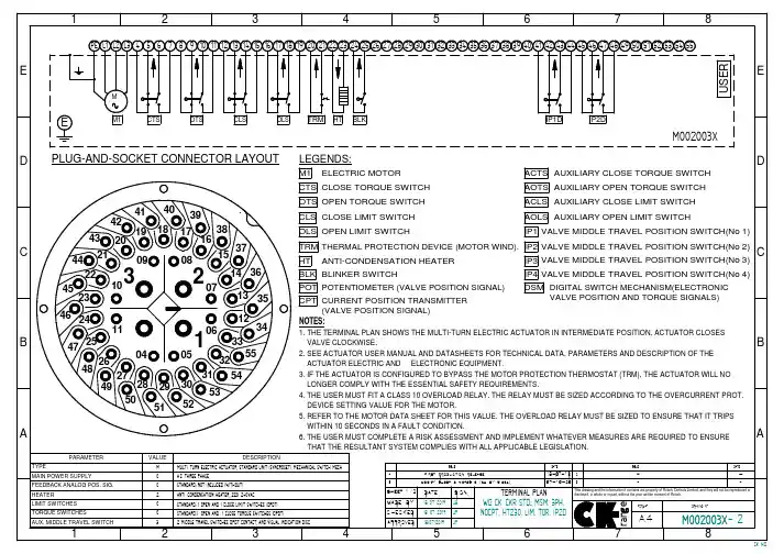
DJFK6型角阀控制器说明书
- 格式:doc
- 大小:103.00 KB
- 文档页数:9
电动调节阀使用说明格,将面临新的挑战,尤其是在国际矿业巨头继续扩大垄断,谈判双方实力严重失衡的大环境下。
实际上,今年的铁矿石价格谈判时间未到,却早已引起国内外的关注了。
目前,我国铁矿石自给率约为45%至50%,另外一半需要进口,进口分为现货进口和长期协议进口两部分。
作为世界上最大的铁矿石进口国,我国在世界上的地位绝对是举足轻重的。
然而,近几年来,我国钢企参加了几次国际铁矿石价格谈判,但效果都不明显。
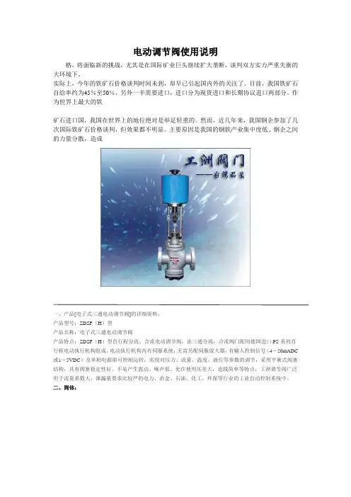
主要原因是我国的钢铁产业集中度低、钢企之间的力量分散,造成一、产品[电子式三通电动调节阀]的详细资料:产品型号:ZDSF(H)型产品名称:电子式三通电动调节阀产品特点:ZDSF(H)型直行程分流、合流电动调节阀,由三通分流,合流阀门配用德国进口PS系列直行程电动执行机构组成。
电动执行机构内有伺服系统,无需另配伺服放大器,有输入控制信号(4-20mADC 或1-5VDC)及单相电源即可控制运转,实现对压力、流量、温度、液位等参数的调节,采用平衡式阀塞结构,具有阀塞稳定性好、不易产生震动、噪声低、允许使用压差大,连线简单等特点,工洲调节阀广泛用于流量系数大,泄漏量要求比较严的电力、冶金、石油、化工、环保等行业的工业自动控制系统中。
二、阀体:形式:三通双座铸造阀公称通径:25-300mm公称压力:PM1.6 4.0 6.4MPa连接形式:法兰式按JB78-59 JB79-59材料:HT200 ZG230—450 ZG1Cr18Ni9TiZG0Cr18Ni12Mo2Ti三、上阀盖:常温型:-20℃-+200℃散热型:-40℃-+450℃压盖形式:螺栓压紧式填料:V型聚四氟乙烯填料、柔性石墨、不锈钢波纹管四、阀内组件:阀芯形式:双导向双座套筒型阀芯流量特性:等百分比特性,线性特性和快开特性材料:1Cr18Ni9Ti 0Cr18Ni12Mo2Ti五、执行机构:类型:可选PS、3810、ZAZ型(DN100以内)、DKZ型(DN100以上)系列电子式直行程执行机构。
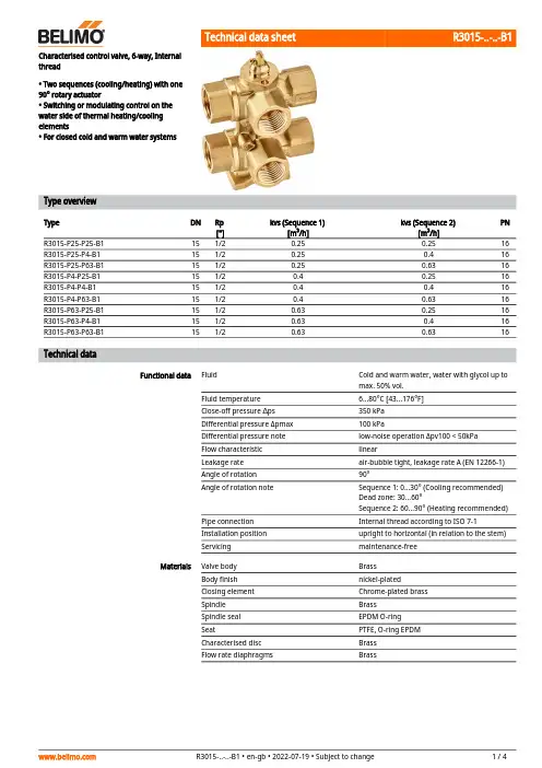
R3015-..-..-B1Characterised control valve, 6-way, Internalthread• Two sequences (cooling/heating) with one 90° rotary actuator• Switching or modulating control on the water side of thermal heating/cooling elements• For closed cold and warm water systemsType overviewTypeDN Rp ["]kvs (Sequence 1)[m³/h]kvs (Sequence 2)[m³/h]PN R3015-P25-P25-B1151/20.250.2516R3015-P25-P4-B1151/20.250.416R3015-P25-P63-B1151/20.250.6316R3015-P4-P25-B1151/20.40.2516R3015-P4-P4-B1151/20.40.416R3015-P4-P63-B1151/20.40.6316R3015-P63-P25-B1151/20.630.2516R3015-P63-P4-B1151/20.630.416R3015-P63-P63-B1151/20.630.6316Technical dataFunctional dataFluidCold and warm water, water with glycol up to max. 50% vol.Fluid temperature 6...80°C [43...176°F]Close-off pressure ∆ps 350 kPa Differential pressure Δpmax 100 kPaDifferential pressure note low-noise operation Δpv100 < 50kPa Flow characteristic linearLeakage rate air-bubble tight, leakage rate A (EN 12266-1)Angle of rotation 90°Angle of rotation noteSequence 1: 0...30° (Cooling recommended)Dead zone: 30...60°Sequence 2: 60...90° (Heating recommended)Pipe connection Internal thread according to ISO 7-1Installation position upright to horizontal (in relation to the stem)Servicingmaintenance-free MaterialsValve body Brass Body finish nickel-plated Closing element Chrome-plated brass Spindle Brass Spindle seal EPDM O-ring SeatPTFE, O-ring EPDM Characterised disc Brass Flow rate diaphragmsBrassR3015-..-..-B1•••••Mode of operationPressure compensationRecommended installation positionsWater quality requirements Safety notesThe valve has been designed for use in stationary heating, ventilation and air-conditioning systems and must not be used outside the specified field of application, especially in aircraft or in any other airborne means of transport.Only authorised specialists may carry out installation. All applicable legal or institutional installation regulations must be complied during installation.The valve does not contain any parts that can be replaced or repaired by the user.The valve may not be disposed of as household refuse. All locally valid regulations and requirements must be observed.When determining the flow rate characteristic of controlled devices, the recognised directives must be observed.Product featuresThe 6-way characterised control valve is adjusted by a rotary actuator. The actuator is connected by a modulating control system or a bus signal and moves the ball of the ball valve to the position dictated by the control signal.If the valve is adjusted in the clockwise direction (till the end stop), e.g. the cooling sequence is completely enabled; if the valve is adjusted in the counter-clockwise direction (90°), e.g. the heating sequence is completely enabled.In cases of combined heating/cooling control elements, the fluid remains in the control element when in the closed position (no heating or cooling). The pressure of the enclosed fluid can rise or fall due to changes in fluid temperature caused by the ambient temperature. The 6-way characterised control valves have an integrated pressure relief function for the purpose of compensating for such pressure changes.The pressure relief function is active in the closed position (45°) of the valve; reliable separation of Sequences 1 and 2 continues. For additional information, consult the notes for project planning for the 6-way characterised control valve.AccessoriesMechanical accessoriesDescriptionType Elbow 90° male/female DN 15 Rp 1/2, R 1/2, Set of 2 pcs.P2P15PE-1GE Fixing bracket for 6-way valve DN 15/20ZR-004Pipe connector for ball valve DN 15ZR2315Installation notesThe ball valve can be installed upright to horizontal. The ball valve may not be installed in ahanging position, i.e. with the spindle pointing downwards.The water quality requirements specified in VDI 2035 must be adhered to.Belimo valves are regulating devices. For the valves to function correctly in the long term, they must be kept free from particle debris (e.g. welding beads during installation work). The installation of a suitable strainer is recommended.R3015-..-..-B1ServicingFlow directionValve characteristic curve Using an additional flow limiterBall valves and rotary actuators are maintenance-free.Before any service work on the control element is carried out, it is essential to isolate the rotary actuator from the power supply (by unplugging the electrical cable if necessary). Any pumps in the part of the piping system concerned must also be switched off and the appropriate slide valves closed (allow all components to cool down first if necessary and always reduce the system pressure to ambient pressure level).The system must not be returned to service until the ball valve and the rotary actuator have been correctly reassembled in accordance with the instructions and the pipeline has been refilled by professionally trained personnel.The flow direction must be observed. The position of the ball can be identified from the L-marking on the spindle.The lower diagram shows the valve characteristic curve in relation to the ball position.When using additional flow limiting valves (e.g. PIQCV C2..QP(T)-.. with manual flow rate setting) or an additional pressure-independent control valve (e.g. motorised PIQCV) at the system level, it is not necessary to use the flow characterised disc in the 6-way valve in the system to reduce the kvs value.R3015-..-..-B1 DimensionsDimensional drawingsThe actuator dimensions can be found on the respective actuator data sheet.Further documentation• The complete product range for water applications• Data sheets for actuators• Installation instructions for actuators and/or ball valves• Notes for project planning for 6-way characterised control valves。
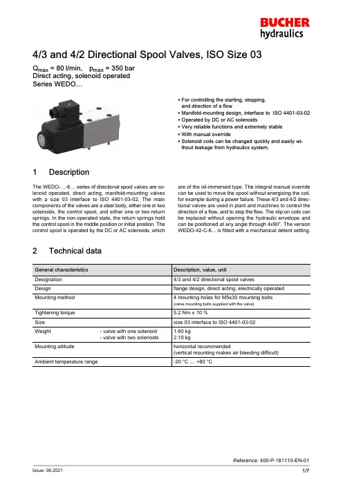
4/3 and 4/2 Directional Spool Valves, ISO Size 03Q max = 80 l/min, p max = 350 bar Direct acting, solenoid operatedSeries WEDO…1/7Reference: 400-P-181110-EN-01Issue: 08.2021S For controlling the starting, stopping,and direction of a flowS Manifold-mounting design, interface to ISO 4401-03-02S Operated by DC or AC solenoidsS Very reliable functions and extremely stable S With manual overrideS Solenoid coils can be changed quickly and easily without leakage from hydraulics system.1DescriptionThe WEDO-…-6… series of directional spool valves are solenoid operated, direct acting, manifold-mounting valves with a size 03 interface to ISO 4401-03-02. The main components of the valves are a steel body, either one or two solenoids, the control spool, and either one or two return springs. In the non-operated state, the return springs hold the control spool in the middle position or initial position. The control spool is operated by the DC or AC solenoids, whichare of the oil-immersed type. The integral manual override can be used to move the spool without energising the coil,for example during a power failure. These 4/3 and 4/2 directional valves are used in plant and machines to control the direction of a flow, and to stop the flow. The slip-on coils can be replaced without opening the hydraulic envelope and can be positioned at any angle through 4x90°. The version WEDO-42-C-6... is fitted with a mechanical detent setting.2Technical dataGeneral characteristics Description, value, unitDesignation 4/3 and 4/2 directional spool valvesDesignflange design, direct acting, electrically operated Mounting method 4 mounting holes for M5x30 mounting bolts(valve mounting bolts supplied with the valve)Tightening torque 5.2 Nm ± 10 %Size size 03 interface to ISO 4401-03-02Weight- valve with one solenoid - valve with two solenoids1.60 kg2.10 kgMounting attitudehorizontal recommended(vertical mounting makes air bleeding difficult)Ambient temperature range-20 °C … +80 °C400-P-181110-EN-01/08.2021Series WEDO…2/7Hydraulic characteristics Description, value, unit Maximum operating pressure - ports A, B, P - port T350 bar 210 bar Maximum flow rate DC AC80 l/min 60 l/minFlow direction see table “Symbols / Spool types”Hydraulic fluidHL and HLP mineral oil to DIN 51 524;HEES biodegradable fluids;for other fluids, please consult BUCHER Hydraulic fluid temperature range -20 °C … +80 °CViscosity range10…500 mm 2/s (cSt), recommended 15...250 mm 2/s (cSt)Minimum fluid cleanlinessCleanliness class to ISO 4406 : 1999class 20/18/15Electrical characteristics Description, value, unitStandard - Supply voltage 12 V DC, 24 V DC / 110 V AC, 220 V AC (50 … 60 Hz)Supply voltage tolerance ± 10 %Ambient temperature range -20 °C … +50 °C Nominal power consumption DC AC 30/31 W energising 225 VA (RMS) / holding39 VA (RMS)Switching time bei 40 l/min, 175 barDC AC45 ms (energising)28 ms (deenergising)15 ms (energising)23 ms(deenergising)Depending on pressure, flow rate, pressure drop and viscosity as well as dwell time under pressure, the switching times may vary from the the stated values.Relative duty cycle100 %Protection class to ISO 20 653 / EN 60 529IP65(with appropriate mating connector and proper fitting and sealing)Electrical connectionDIN EN 175301-803, 3-pin 2 P+E (standard)for other connectors, see “Ordering code”400-P-181110-EN-01/08.2021 Series WEDO…3/73Symbols / Spool types400-P-181110-EN-01/08.2021Series WEDO…4/74Performance graphsmeasured with oil viscosity 33 mm 2/s (cSt), coil at steady-state temperature and 10 % undervoltage Δp = f (Q) Pressure drop - Flow rate characteristicA, B, C, D, F, G, H and J spool0Q [l/min]60504030201024681012p [bar]P0434.ai43215678Spool type Flow directionP % A P % B P % T A % T B % T A % B B % A A / B / C 66–55––AN / BN / CN55–22––D 55–22––F 6* 46** 4–337 + +7 + +G 66–3* 13+ 1––H 44 4 +22––J66844––*in mid–position, B closed **in mid–position, A closed +in mid–position, A + B closed ++in mid–position, P closed400-P-181110-EN-01/08.2021Series WEDO…5/7p = f (Q) Performance limits with AC-solenoid coil operating at 50 Hz0Q [l/min]60504030201050100150200250350p [bar]P0435.ai4321300Spool typeFlow directionA 2B 2C 2D 1F 1G 4H 1J3p = f (Q) Performance limits - wIth DC-solenoid coil0Q [l/min]80705040301050100150200300350p [bar]P0436.ai542120603235250Spool typeFlow directionA 3B 3C 3D 1F 2G 5H 2J4IMPORTANT!The indicated performance limits apply when symmetrical flows pass through the valve.For non-symmetrical flows, the max. flows are substantially reduced, in worst cases to 33%.400-P-181110-EN-01/08.2021Series WEDO…6/75Dimensions & sectional view4/3 spool valve (spring centred)4/2 spool valve (pulse signal, detented)1)4/2 spool valve (1-solenoid model, A or B side)± 5%M A Seal kit NBR no. DS-150-V 3)Item Qty. 5)Qty. 6)Description 144O-ring no. 012∅ 9,25 x 1,78N90212O-ring no. 022∅25,12 x 1,78N90312O-ringno. 213∅23,39 x 3,53N90IMPORTANT!1)With manual override 2)Valve mounting bolts M5x30(included in the delivery)3)Seal kit with FKM (Viton) seals no. DS-150-V 4)Required surface finish on the mounting face (valve pad)5)4/2 valves (1 solenoid)6)4/3 valves (2 solenoid)400-P-181110-EN-01/08.2021Series WEDO…7/76Installation informationATTENTION!Only qualified personnel with mechanical skills may carry out any maintenance work. Generally,the only work that should ever be undertaken is to check, and possibly replace, the seals. When changing seals, oil or grease the new seals thoroughly before fitting them.IMPORTANT!When fitting the valves, use the specified tightening torque for the mounting bolts. No adjustments are necessary, since the cartridges are set in the factory.7Ordering codeWEDO =42=43=… =6=V =1 ... 9=... =D =A=(blank)=M100=8Related data sheetsReference (Old no.)Description400-P-030101(i-30)Size 03 interface to ISO 4401-03-02E 2021 by Bucher Hydraulics AG Frutigen, CH-3714 Frutigen****************************All rights reserved.Data is provided for the purpose of product description only, and must not be construed as warranted characteristics in the legal sense. The information does not relieve users from the duty of conducting their own evaluations and tests. Because the products are subject to continual improvement, we reserve the right to amend the product specifications contained in this catalogue.Classification: 430.300.-.315.305.300。
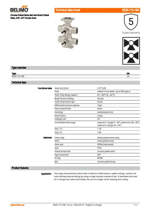
B320-116-186ApplicationChrome Plated Brass Ball and Nickel Plated Stem, 3/4", NPT Female EndsType overviewTypeDN B320-116-18620Technical dataFunctional dataValve size [mm]0.75" [20]Fluidchilled or hot water, up to 60% glycol Fluid Temp Range (water)43...180°F [6...82°C]Body Pressure Rating 232 psi Close-off pressure ∆ps 50 psi Differential pressure Δpmax 15psi Flow characteristic linearServicing maintenance-free Flow Pattern 6-way Leakage rate0%Controllable flow range sequence 1 (angle 0...30°), dead zone (30...60°), sequence 2 (angle 60...90°)Seq 1 Cv 1.16Seq 2 Cv1.86MaterialsValve body Nickel-plated brass body Stem nickel-plated brass Stem seal EPDM (lubricated)SeatPTFECharacterized disc chrome plated steel Pipe connection NPT O-ring EPDMBallchrome plated brassProduct featuresThe 6-way characterized control valve is ideal for chilled beams, radiant ceilings, and fan coil units offering reduced wiring by using a single actuator instead of two. It eliminates the need for a change-over valve and enables the use of a single coil for heating and cooling.B320-116-186 Operation A loop pressure relief is designed into port number two (2). This allows the increased pressureto dissipate to the supply loop on port number one (1). This is intended to release any pressurebuild up in the loop (coil) when the valve is in the closed position and is isolated from the systemexpansion vessel. The change in pressure occurs due to a change in the media temperature inthe coil while isolated from the pressure vessel. The pressure relief does not affect the efficiencyof the system because cross-flow cannot occur between the heating and cooling loops. Thesystem loops (heating/cooling) should share a common expansion vessel to keep the systempressure and volume balanced.Flow/Mounting detailsAccessoriesMechanical accessories Description TypeFixing bracket for 6-way valve DN 15/20ZR-004 DimensionsType DN WeightB320-116-18620 4.63 lb [2.1 kg]A B C D E F G H1H27.5" [191] 3.9" [100]9.0" [229]7.6" [194] 2.0" [51]2.0" [51]2.4" [60]1.2" [30]0.6" [15]LRX24-MFTModulating, Non-Spring Return, 24 V, Multi-Function Technology®Technical dataElectrical dataNominal voltageAC/DC 24 V Nominal voltage frequency 50/60 HzNominal voltage rangeAC 19.2...28.8 V / DC 21.6...28.8 V Power consumption in operation 2.5 W Power consumption in rest position 1.2 W Transformer sizing 5 VAElectrical Connection18 GA plenum cable with 1/2" conduitconnector, degree of protection NEMA 2 / IP54, 1 m 3 m and 5 mOverload Protection electronic thoughout 0...90° rotation Electrical Protectionactuators are double insulated Functional dataOperating range Y 2...10 VOperating range Y note 4...20 mA w/ ZG-R01 (500 Ω, 1/4 W resistor)Input Impedance100 kΩ for DC 2...10 V (0.1 mA), 500 Ω for 4...20 mA, 1500 Ω for PWM and On/Off Operating range Y variable Start point 0.5...30 V End point 2.5...32 VOperating modes optional variable (VDC, on/off, floating point)Position feedback U 2...10 V Position feedback U note Max. 0.5 mA Position feedback U variable VDC variableDirection of motion motor selectable with switch 0/1Manual override external push button Angle of rotation 90°Angle of rotation note adjustable with mechanical stop Running Time (Motor)150 s / 90°Running time motor variable 35...150 s Noise level, motor 35 dB(A)Position indicationMechanically, pluggable Safety dataPower source ULClass 2 Supply Degree of protection IEC/EN IP54Degree of protection NEMA/UL NEMA 2Enclosure UL Enclosure Type 2Agency Listing cULus acc. to UL60730-1A/-2-14, CAN/CSA E60730-1:02, CE acc. to 2014/30/EU Quality Standard ISO 9001UL 2043 CompliantSuitable for use in air plenums per Section 300.22(C) of the NEC and Section 602 of the IMCAmbient humidityMax. 95% RH, non-condensingLRX24-MFTFootnotesSafety dataAmbient temperature -22...122°F [-30...50°C]Storage temperature -40...176°F [-40...80°C]Servicingmaintenance-free Weight Weight1.5 lb [0.70 kg]MaterialsHousing material Galvanized steel and plastic housing†Rated Impulse Voltage 800V, Type action 1.B, Control Pollution Degree 3.AccessoriesGatewaysDescriptionType Gateway MP to BACnet MS/TP UK24BAC Gateway MP to Modbus RTU UK24MOD Gateway MP to LonWorksUK24LON Electrical accessoriesDescriptionType Battery backup system, for non-spring return models NSV24 US Battery, 12 V, 1.2 Ah (two required)NSV-BAT Auxiliary switch 1 x SPDT add-on S1A Auxiliary switch 2 x SPDT add-onS2AFeedback potentiometer 140 Ω add-on, grey P140A GR Feedback potentiometer 1 kΩ add-on, grey P1000A GR Feedback potentiometer 10 kΩ add-on, grey P10000A GR Feedback potentiometer 2.8 kΩ add-on, grey P2800A GR Feedback potentiometer 500 Ω add-on, grey P500A GR Feedback potentiometer 5 kΩ add-on, greyP5000A GR ToolsDescriptionTypeConnection cable 10 ft [3 m], A: RJ11 6/4 ZTH EU, B: 3-pin Weidmüller and supply connectionZK4-GEN Service Tool, with ZIP-USB function, for programmable and communicative Belimo actuators, VAV controller and HVAC performance devicesZTH USElectrical installationINSTALLATION NOTESProvide overload protection and disconnect as required.Actuators may be connected in parallel. Power consumption and input impedance must beobserved.Actuators may also be powered by DC 24 V.Only connect common to negative (-) leg of control circuits.A 500 Ω resistor (ZG-R01) converts the 4...20 mA control signal to 2...10 V.Control signal may be pulsed from either the Hot (Source) or Common (Sink) 24 V line.For triac sink the Common connection from the actuator must be connected to the Hotconnection of the controller. Position feedback cannot be used with a triac sink controller; theactuator internal common reference is not compatible.IN4004 or IN4007 diode. (IN4007 supplied, Belimo part number 40155).Actuators with plenum cable do not have numbers; use color codes instead.Meets cULus requirements without the need of an electrical ground connection.Warning! Live electrical components!During installation, testing, servicing and troubleshooting of this product, it may be necessary to work with live electrical components. Have a qualified licensed electrician or other individual who has been properly trained in handling live electrical components perform these tasks. Failure to follow all electrical safety precautions when exposed to live electrical components could result in death or serious injury.LRX24-MFT Wiring diagramsOn/Off Floating PointVDC/mA Control PWM ControlOverride Control。
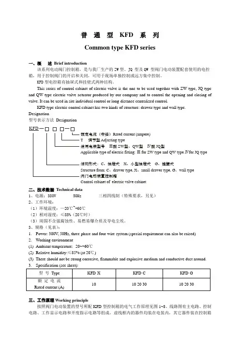
额定电流(安培)调节型适用电装型号Ⅲ配型、型Ⅳ配型结构形式:、抽屉式、小型R ated current (am pere)T A djusting typeZ W Q W JQ A pplicable type of electric fitting: for ZW type and Q W type.C X G Structure from : C draw er type, X sm all C ontrol cabinet of electric valve cabinetⅢⅣ抽屉式、挂壁式、、、阀门电动装置控制箱for JQ type draw er type, G wall type K F D —— 普 通 型 KFD 系 列 Common type KFD series一、概 述 Brief introduction该系列电动阀门控制箱,是与我厂生产的ZW 型、JQ 型及QW 型阀门电动装置配套使用的电控箱,用于控制阀门的开启和关闭,可用于现场单独控制或远方集中控制。
KFD 型电控箱有抽屉式和挂壁式两种结构。
This series of control cabinet of electric valve is the one to be used together with ZW type, JQ type and QW type electric valve actuator produced by our company and to control the opening and closing of valve. It can be used in site individual control or long-distance centralized control.KFD type electric control cabinet has two kinds of structure: drawer type and wall type. Designation型号表示方法 Designation二、技术数据 T echnical data1、电源:380V 50Hz 三相四线制(特殊要求,另见)2、工作环境:(1)环境温度:—20℃~+60℃ (2)相对湿度:≤85%(20℃时)(3)周围不含强腐蚀性、易燃易爆介质及导电尘埃。
调节阀电动调节阀是工业自动化过程控制中的重要执行单元仪表;随着工业领域的自动化程度越来越高,正被越来越多的应用在各种工业生产领域中;与传统的气动调节阀相比具有明显的优点:电动调节阀节能只在工作时才消耗电能,环保无碳排放,安装快捷方便无需复杂的气动管路和气泵工作站;阀门按其所配执行机构使用的动力,按其功能和特性分为线性特性,等百分比特性及抛物线特性三种阀门结构由电动执行机构和调节阀连接组合后经过机械连接装配、调试安装构成电动调节阀;主要零件零件材料:阀体、阀盖、填料压盖、阀杆、阀瓣、密封圈、指示标、阀杆螺母、螺帽套材料:灰铸铁、铸钢、不锈钢、黄铜工作原理工作电源:DC24V,AC220V,AC380V等电压等级;输入控制信号:DC4-20MA或者DC1-5V;反馈控制信号:DC4-20MA负载电阻碍500欧姆以下通过接收工业自动化控制系统的信号如:4~20mA来驱动阀门改变阀芯和阀座之间的截面积大小控制管道介质的流量、温度、压力等工艺参数;实现自动化调节功能;新型电动调节阀执行器内含饲服功能,接受统一的4-20mA或1-5V·DC的标准信号,将电流信号转变成相对应的直线位移,自动地控制调节阀开度,达到对管道内流体的压力、流量、温度、液位等工艺参数的连续调节;流量特性电动调节阀的流量特性,是在阀两端压差保持恒定的条件下,介质流经电动调节阀的相对流量与它的开度之间关系;电动调节阀的流量特性有:线性特性,等百分比特性及抛物线特性三种;应用领域电力、化工、冶金、环保、水处理、轻工、建材等工业自动化系统领域;安装电动调节阀最适宜安装为工作活塞上端在水平管线下部;温度传感器可安装在任何位置,整个长度必须浸入到被控介质中;电动调节阀一般包括驱动器,接受驱动器信号0-10V或4-20MA来控制阀门进行调节,也可根据控制需要,组成智能化网络控制系统,优化控制实现远程监控;电气原理动作原理:电机电源220VAC 或者380VAC,控制信号4~20mA,阀里面有控制器,控制器把电流信号转换为步进电机的角行程信号,电机转动,由齿轮,杠杆,或者齿轮加杠杆,带动阀杆运作,实现直行程或角行程反馈:电机运行,通过齿轮运转,由三接头的滑动变阻器输出阀门的定位信号,此外还有三根线的限位信号全开,全闭;公共线分类ZDLW电子式电动调节阀ZAZP型电动直通单座调节阀ZAZN电动直通双座调节阀ZAZM/P电动套筒调节阀ZAZQX型电动三通合流分流调节阀ZAZS型电动角型调节阀ZAZS型电动角型调节阀HTNT961Y减温水调节阀ZAZT、ZAZTC型电动隔膜调节阀ZAZPF46-10W型电动衬氟波纹管调节阀ZDLP型电子式电动单座调节阀ZDLN型电子式电动双座调节阀ZDLMP型电子式电动精小型套筒调节阀ZDZDLPM型智能型电动调节阀ZDLQ、ZDLX 型电子式电动三通调节阀ZDLW电子式电动调节阀类似产品自力式调节阀与电动调节阀功能相似的还有:;自力式调节阀不需外加能源,通过调节设定点控制温度;当温度升高,阀门根据温度变化成比例的关闭;自力式调节阀包含一个和一个包含一个温度传感器、一个设定点调整器、一个毛细管和一个工作活塞,电动执行器依靠选择不同的温度状态应用;温度调节阀根据液体膨胀原理操作,如果在传感器上的温度升高,将使得液体填充物同时加热并膨胀,在工作活塞的作用下阀门关闭,此时将冷却介质;通过设定点键可以一步步调整,电动二通阀可以在标尺上读出;所有的温控器都配有一个超温安全保护设备;使用维修随着工业的迅速发展,电动调节阀在冶金、石油化工等领域的应用越来越广泛,其稳定性、可靠性也显得越来越重要,它的工作状态的好坏将直接影响自动控制过程,本文将详细阐述电动调节阀的使用和维修;电子式电动单座调节阀,是由直行程全电子式电动执行机构和顶导向式直通低流阻单座阀组成;具有结构紧凑、重量轻、动作灵敏、流体通道呈S流线型、压降损失小、阀容量大、流量特性精确,直接接受调节仪表输入的4-20mA DC 0-10mA DC或1-5V DC等控制信号及单相电源即可控制运转,实现对工艺管路流体介质的自动调节控制,广泛应用于精确控气体、液体、蒸汽等介质的工艺参数如压力、流量、温度、液位等参数保持在给定值;安装使用注意事项新设计、安装的控制系统,为了确保调节阀在开车时能正常工作,并使系统安全运行,新阀在安装之前,应首先检查阀上的铭牌标记是否与设计要求相符;同时还应对以下项目进行调试;基本误差限;全行程偏差;回差;死区;泄漏量在要求严格的场合时进行;如果是对原系统中调节阀进行了大修,除了对上述各项进行校验外,还应对旧阀的填料函和连接处等部位进行密封性检查;在现场使用中,很多往往不是因为调节阀本身质量所引起,而是对调节阀的安装使用不当所造成,如安装环境、安装位置及方向不当或者是管路不清洁等原因所致;因此电动调节阀在安装使用时要注意以下几方面:⑴调节阀属于现场仪表,要求环境温度应在-25~60℃范围,相对湿度≤95%;如果是安装在露天或高温场合,应采取防水、降温措施;在有震源的地方要远离振源或增加防振措施;⑵调节阀一般应垂直安装,特殊情况下可以倾斜,如倾斜角度很大或者阀本身自重太大时对阀应增加支承件保护;⑶安装调节阀的管道一般不要离地面或地板太高,在管道高度大于2 m时应尽量设置平台,以利于操作手轮和便于进行维修;⑷调节阀安装前应对管路进行清洗,排除污物和焊渣;安装后,为保证不使杂质残留在阀体内,还应再次对阀门进行清洗,即通入介质时应使所有阀门开启,以免杂质卡住;在使用手轮机构后,应恢复到原来的空档位置;⑸为了使调节阀在发生故障或维修的情况下使生产过程能继续进行,调节阀应加旁通管路;同时还应特别注意,调节阀的安装位置是否符合工艺过程的要求;⑹电动调节阀的电气部分安装应根据有关电气设备施工要求进行;如是隔爆型产品应按爆炸危险场所电气设备安装规范要求进行安装;如现场导线采用SBH型或其它六芯或八芯、外径为 mm左右的胶皮安装电缆线;在使用维修中,在易爆场所严禁通电开盖维修和对隔爆面进行撬打;同时在拆装中不要磕伤或划伤隔爆面,检修后要还原成原来的隔爆要求状态;⑺执行机构的减速器拆修后应注意加油润滑,低速电机一般不要拆洗加油;装配后还应检查阀位与阀位开度指示是否相符;调节阀系列选型系统应用调节阀选型软件之所以上升为选型系统,有它的创新点所在:1 选型系统借助互联网,将企业在全国各地销售网点的订货信息自动传输至企业本部信息系统中,进行销售商务处理自动报价、合同评审、计划排产等,改变以往发邮件再人工重复录入的工作模式;2 远程自动判别订货产品是属于常规产品或特殊产品,调节阀产品选型系统可以使销售人员在公司外与客户签订合同前,利用软件系统,自动判别所选产品是否属于特殊品,为商务洽谈技术提供依据;3 可远程更新软件版本,随时可将产品的更新信息发布到各销售网点,保证销售选型人员得到的始终是最新的产品数据,从而保证了选型人员所选的产品信息与企业内部设计信息一致,减少了中间的出错环节;性能1.由于不需要进行系统调试,所以省去许多麻烦,节约了大量的时间,缩短竣工日期;2.由于不用使用阀门组和用于分层控制的阀门,所以为您节约了较多的管材,保温材料及安装费用和时间;3.使水系统时时刻刻都处于平衡状态,所以无论安装分期施工或设备分期使用都不会影响水系统的平衡;4.即使工程后期或投入运行后因改变某些用途而需要改变某些区域的水系统设计,也不会影响其他区域的水系统设计,更不会影响区域的水系统平衡;5.由于整个系统处于动态平衡状态,所以制冷机组及水泵将以最节能状态运行,节省了运行维护费用;6.由于系统的流量平衡是自动进行的,使安装维护更加便利,并杜绝了人为操作失误破坏平衡的可能;特点用途具有体积小,重量轻、连线简单、流量大、调节精度高等特点,广泛应用于电力、石油、化工、冶金、环保、轻工、教学和科研设备等行业的工业过程自动控制系统中;电动调节阀阀内组件:阀芯型式:上导单座套筒柱塞型阀芯流量特性:直线特性、等百分比特性或快开特性材料:1Cr18Ni9Ti 0Cr18Ni12Mo2Ti电动调节阀的用途及作用用于调节工业自动化过程控制领域中的介质流量、压力、温度、液位等工艺参数;电动调节阀适用范围空调、供暖、蒸气用电动调节阀通风、生活热水等民用系统及化工、石油冶金、电力轻工业等各行业生产过程中的自动控制;阀体结构选用要点⒈ 电动调节阀选用主要控制参数为:公称直径、设计公称压力、介质允许温度范围、流量系数等;⒉ 对于要求流量和开启高度成正比例关系的严格场合,应选用专用调节阀;球阀和蝶阀一般粗调时可以选用;⒊阀门的密封性能是考核阀门质量优劣的主要指标之一;阀门的密封性能主要包括两个方面,即内漏和外漏;内漏是指阀座与关闭件之间对介质达到的密封程度;外漏是指阀杆填料部位的泄露,中口垫片部位的泄露以及阀体因铸造缺陷造成的泄露;外漏是不允许发生的;⒋ 调节阀理想流量特性有快开、抛物线、线性、等百分比四种,需根据实际工作流量特性选择具有合适流量特性的调节阀;流量特性的选择原则见表1;表1 按配管情况选择阀门的特性注:S=调节阀全开时的压力损失/调节阀所在串联支路的总压力损失;为了避免通过阀门的水流速过高并尽量节省水泵功耗,宜使阀门工作状态的S≤.⒌ 调节阀公称直径的选取应根据所需阀门流通能力确定;调节阀公称直径不应过大或过小;过大,增加工程成本,并且阀门处于低百分比范围内,调节精度降低,使控制性能变差;过小,增加系统阻力,甚至会出现阀门100%开启时,系统仍无法达到设定的容量要求;6、调节阀的调节压差和关断压差对于调节阀,其允许的调节压差和关断压差是其选型的重要指标;实际压差如高于调节阀允许的调节压差,阀门会出现不能准确调节的问题,严重的会损伤阀门执行器;安装要点⒈ ;阀门的安装位置、高度、进出口方向必须符合符合口方向;设计要求,连接应牢固紧密;⒉ ;阀门可用各种形式的端部与管路连接;其中最主要的连接方式有螺纹、法兰及焊接连接;法兰连接时,若温度超过350℃时,由于螺栓、法兰和垫片蠕变松弛,应选择耐高温螺栓材料;⒊ ;阀门安装前必须进行外观检查,阀门的铭牌应符合现行国家标准GB12220通用阀门标志的规定;对于工作压力大于及在主干管上起到切断作用的阀门,应进行强度和严密性试验,合格后方准使用;其他阀门可不单独进行试验,待在系统试压中检验;⒋ ;强度试验时,试验压力为公称压力的倍,持续时间不少于5min,阀门的壳体、填料应无渗漏;⒌ ;严密性试验时,试验压力为公称压力的倍;试验压力在试验持续的时间内应保持不变,时间应符合表2的规定,以阀瓣密封面无渗漏为合格;⒍ ;公称通径:DN15~500表2 阀门压力持续时间执行标准产品标准GB/T13927-92通用阀门压力试验JB/T5296-91通用阀门流量系数和流阻系数的试验方法JB/T8528-1997普通型阀门电动装置技术条件GB12220-89通用阀门标志工程标准GB50243-2002通风与空调工程施工质量验收规范GB50242-2002建筑给水排水及采暖工程施工质量验收规范特点调节阀主要由阀体、套筒、阀瓣、阀杆等零件组成;套筒和阀瓣上都开有节流孔通过阀瓣在阀座内回转来改变过流面积,调节流量;配ZKJ型或其它型电动角行程执行器可实现遥控和自动控制;调节阀广泛应用于给水管路中作调节流量使用;也可在油品管路中使用;性能⒈由于不需要进行系统调试,所以省去许多麻烦,节约了大量的时间,缩短竣工日期;⒉由于不用使用阀门组和用于分层控制的阀门,所以为您节约了较多的管材,保温材料及安装费用和时间;⒊使水系统时时刻刻都处于平衡状态,所以无论安装分期施工或设备分期使用都不会影响水系统的平衡.⒋即使工程后期或投入运行后因改变某些用途而需要改变某些区域的水系统设计,不会影响其他区域的水系统设计,更不会影响其他区域的水系统平衡;⒌由于整个系统处于动态平衡状态,所以制冷机组及水泵将以最节能状态运行,节省了大量维护费用.⒍由于系统的流量平衡是自动进行的,使安装维护更加便利,并杜绝了人为操作失误破坏平衡的可能.优点除高可靠、全功能、超轻型的特点外,电动调节阀还有如下好处:⑴用电源既方便又节约,省去了建立气源站的一系列费用;⑵用“气动阀+电气阀门定位器+气源”的复杂方式,它不只是增加了费用,反而带来了可靠性的下降环节越多,可靠性差的因素增加;⑶从经济性上看,除省去气源站的费用外,还省去电气阀门定位器的费用:一台好的进口的电气阀门定位器,通常在5000~6000元以上,更好的在8000~10000的价位上,而这个价位基本上可购回上述高可靠的电子式执行机构;⑷环节减少了,相应减少了维修工作量;缺点电动调节阀也不是没有缺点:电机运行产生的内热会导致热保护,使调节阀停止工作;由于电机必须经过多级减速才能输出力矩,所以运行速度还不是很快,在有些要求快速启闭的场合还不适用,大力矩和高速,还是一个比较难以解决的矛盾;由于运动部件多,相对容易产生故障,尤其在调节频繁的工况,容易产生电机热保护、减速齿轮损坏、模块可控硅烧毁等故障,在这种工况下,最好还是选用气动调节阀比较适宜;。
Instruction ManualElectric Actuator - Guide Type Series LEGMotor: Battery-less absolute encoder [Step 24 VDC]The intended use of this Electrical Actuator is to convert an electrical input signal into mechanical motion.These safety instructions are intended to prevent hazardous situations and/or equipment damage. These instructions indicate the level of potential hazard with the labels of “Caution,” “Warning” or “Danger.” They are all important notes for safety and must be followed in addition to International Standards (ISO/IEC) *1), and other safety regulations.*1) ISO 4414: Pneumatic fluid power - General rules relating to systems. ISO 4413: Hydraulic fluid power - General rules relating to systems.IEC 60204-1: Safety of machinery - Electrical equipment of machines. (Part 1: General requirements)ISO 10218-1: Manipulating industrial robots -Safety. etc.∙ Refer to the product catalogue, Operation Manual and Handling Precautions for SMC Products for additional information. ∙ Keep this manual in a safe place for future reference.Warning∙ Alwaysensure compliancewith relevantsafetylaws and standards.∙ All work must be carried out in a safe manner by a qualified person in compliance with applicable national regulations.∙ The actuator and the controller are sold together as a package. When purchasing the actuator separately, confirm that the combination of the controller and the actuator is compatible.∙ For further safety instructions for the actuator and for the controller refer to the operation manual for each product on the SMC website (URL: https:// ).2 SpecificationsNotes*1) Horizontal: Workload changes according to the distance from theplate to the centre of gravity of the load. Check the “Model Selection” in the catalogue.Vertical: Speed changes according to the workload. Check the “Model Selection” in the catalogue.The workload is changed by the eccentric distance. Check the “Model Selection” in the catalogue.*2) The weight of transferred object is when using a stopper. *3) Pushing force accuracy is ±20% (F.S.).*4) Pushing force is the set pushing force shown below. Pushing forcevaries depending on the motor type.* The pushing force values for Battery-less absolute (Step motor 24VDC) / Size 25:30% to 50%, Size 32:30% to 70%, Size 40:20 to 45%. The pushing force values change according to the duty ratio and push ing speed. Check the “Model Selection” in the catalogue. *5) The speed and force may change depending on the cable length,load and mounting conditions, Furthermore, if the cable length exceeds 5 m, then it will decrease by up to 10% for each 5 m. (at 15 m: Reduced by up to 20%).*6) The allowable speed for the pushing operation.*7) Impact resistance: No malfunction occurred when the actuator wastested with a drop tester in both an axial direction and a perpendicular direction to the lead screw (the test was performed with the actuator in the initial state).Vibration resistance: No malfunction occurred in a test ranging between 45 to 2000 Hz. The test was performed in both an axial direction and a perpendicular direction to the lead screw (the test was performed with the actuator in the initial state).*8) The power (including the controller) is when the actuator is operating.This value can be used for the selection of the power supply. *9) With lock only. *10) F or an actuator with lock, add the power consumption for the lock.2.2 Actuator Weight Top mounting typeIn-line typeWarningFor special products which include a suffix of “-X#”, “-D#”, please refer to the customer drawing of that specific product.3 Installation3.1 InstallationWarning∙ Do not install the product unless the safety instructions have been read and understood.∙ Do not use the product outside of its allowable specification.∙ Ensure the product is sized correctly and is suitable for the application. ∙ When installing, inspecting or performing maintenance on the product,be sure to turn off the power supplies. Then, lock it so it cannot be tampered with while work is happening.3.2 EnvironmentWarning∙ Do not use in an environment where corrosive gases, chemicals, salt water or steam are present.∙ Do not use in an explosive atmosphere.∙ Do not expose to direct sunlight. Use a suitable protective cover.∙ Do not install in a location subject to vibration or impact in excess of the product’s specifications .∙ Do not mount in a location exposed to radiant heat that would result in temperatures in excess of the product’s specifications ∙ Prevent foreign particles from entering the product. ∙ Avoid using in the following environments:a) Areas with large amounts of dust or cutting chips that could enter the product.b) Areas where the ambient temperature exceeds the specified range. c) Areas where the ambient humidity exceeds the specified range. d) Areas where strong magnetic or electric fields are generated.e) Areas where there are large amounts of dust or there is exposure to water/oil droplets.f) Areas at altitudes of above 1000 m.Heat radiation performance and withstand voltage may decline as result. For details, consult with SMC.∙ Do not use in an environment where the product is directly exposed to liquid, such as cutting oils.If cutting oil, coolant, or oil mist adheres to the product, failure or increased sliding resistance can result.∙ Install a protective cover when the product is used in an environment directly exposed to foreign matter, such as dust, cutting chips, and spatter. Looseness or increased sliding resistance can result.3.3 MountingWarning∙ Observe the required tightening torque for screws.Unless stated otherwise, tighten the screws to the recommended torque for mounting the product.∙ Do not make any alterations to the product.Alterations made to this product may lead to a loss of durability and damage to the product, which can lead to injury and damage to other equipment and machinery.∙ Do not scratch or dent the sliding parts of the table or mounting face etc., by striking or holding them with other objects. The components are manufactured to precise tolerances, so that even a slight deformation may cause faulty operation or seizure.∙ Do not use the product until it has been verified that the equipment can be operated correctly.After mounting or repair, connect the power supply to the product and perform appropriate functional inspections to check it is mounted correctly.∙ When one side of the actuator is fixed.When an actuator is operated at a high speed with one end fixed and the other free (basic, flange, or direct mount types), a bending moment may act on the actuator due to the vibration generated at the stroke end, which can damage the actuator. In such a case, install a mounting bracket to suppress the vibration of the actuator body, or reduce the speed so that the actuator does not vibrate. Also, use a mounting bracket when moving the actuator body or when a long stroke actuator is mounted horizontally and fixed at one end.∙ Do not apply strong impact or an excessive moment while mounting the product or a workpiece.If an external force above the allowable moment is applied, it may cause play in the guide or an increase in the sliding resistance. ∙ Allow sufficient space for maintenance and inspection.Caution∙ When tightening the screws to install the workpiece or fixture, fix the plate so that it does not rotate, and tighten the screws properly within the specified torque range.This may cause abnormal responses of the auto switch, play in the internal guide or an increase in the sliding resistance.∙ When mounting the product, use screws with adequate length and tighten them to the recommended torque.Tightening with a larger torque than the specified range may cause malfunction while tightening with a smaller torque can allow the displacement of the actuator position. In extreme conditions the actuator could become detached from its mounting position.∙ Keep the flatness of the mounting surface within 0.02 mm when mounting the actuator body and work piece.Insufficient flatness of the work piece or the surface onto which the actuator body is to be mounted can cause increased sliding resistance.Work fixed / Plate tapped typeORIGINAL INSTRUCTIONSMounting / Upper mounting tapped styleMounting / Lower mounting tapped style3.4 LubricationCaution∙ SMC products have been lubricated for life at manufacture, and do notrequire lubrication in service.∙If a lubricant is used in the system, refer to catalogue for details.∙The recommended grease is lithium grade No.24 Wiring4.1 WiringWarning∙ Adjustment, mounting or wiring changes should not be carried out before disconnecting the power supply to the product. Electric shock, malfunction and damage can result. ∙ Do not disassemble the cables.∙ Use only specified cables, otherwise there is a risk of fire or damage. ∙ Do not connect or disconnect the wires, cables and connectors when the power is turned on.Caution∙ Wire the connector correctly and securely.Check the connector for polarity and do not apply any voltage to the terminals other than those specified in the operation manual.∙ Take appropriate measures against noise.Noise in a signal line may cause malfunction. As a countermeasure separate the high voltage and low voltage cables, and shorten the wiring lengths, etc.∙ Do not route input/output wires and cables together with power or high voltage cables.The product can malfunction due to noise interference and surge voltage from power and high voltage cables close to the signal line. Route the wires of the product separately from power or high voltage cables.∙ Take care that actuator movement does not catch cables. ∙ Operate with all wires and cables secured.∙ Avoid bending cables at sharp angles where they enter the product. ∙ Avoid twisting, folding,rotating or applying an external force to the cable.Risk of electric shock, wire breakage, contact failure and loss of control of the product can result. Refer to the relevant operation manual for the bending life of the cable.∙ Do not allow the cables connected to the actuator to move.The motor and lock cables are not robotic cables and can be broken when moved. Therefore, secure the cables and the connectors during set up.∙ Select a “robotic cable (flexible cable)” when repeated bending of the actuator cable is required. Also, do not put cables into a flexible moving tube with a radius smaller than the specified value (50 mm or longer). ∙ Confirm correct insulation.Poor insulation of wires, cables, connectors, terminals etc. can cause interference with other circuits. Also there is the possibility that excessive voltage or current may be applied to the product causing damage.4.2 Actuator Ground connection Caution∙ The Actuator must be connected to ground to shield the actuator from electrical noise.∙ Dedicated grounding should be used. Grounding should be to a D-class ground (resistance of 100Ω or less).∙ Grounding should be performed near the actuator to shorten the wiring distance.∙ The cross-sectional area of the ground wire shall be a minimum of 2 mm 2.∙ Avoid common grounding with other devices. 4.3 Wiring of Actuator to Controller∙ For standard products, refer to the catalogue on the SMC website (URL: https:// ) for the how to order information.6 Outline Dimensions∙ For standard products, refer to the catalogue on the SMC website (URL: https:// ) for outline dimensions.7 Maintenance7.1 General MaintenanceCaution∙ Not following proper maintenance procedures could cause the product to malfunction and lead to equipment damage.∙ If handled improperly electricity and compressed air can be dangerous. ∙ Maintenance of electromechanical and pneumatic systems should be performed only by qualified personnel.∙ Before performing maintenance, turn off the power supply and be sure to cut off the supply pressure. Confirm that the power has been discharged and the air is released to atmosphere.∙ After installation and maintenance, apply operating pressure and power to the equipment and perform appropriate functional and leakage tests to make sure the equipment is installed correctly.∙ If any electrical or pneumatic connections are disturbed during maintenance, ensure they are reconnected correctly and safety checks are carried out as required to ensure continued compliance with applicable national regulations.∙ Do not make any modification to the product.∙ Do not disassemble the product, unless required by installation or maintenance instructions.∙ Incorrect handling can cause an injury, damage or malfunction of the equipment and machinery, so ensure that the procedure for the task is followed.∙ Always allow sufficient space around the product to complete any maintenance and inspection.7.2 Periodical Maintenance∙ Maintenance should be performed according to the table below: ∙ Following any maintenance, always perform a system check. Do not use the product if any error occurs, as safety cannot be assured if caused by any un-intentional malfunction.7.3 Appearance Check∙ The following items should be visually monitored to ensure that the actuator remains in good condition and there are no concerns flagged;・Loose Screws,・Abnormal level of dust or dirt, ・Visual flaws / faults, ・Cable connections,・Abnormal noises or vibrations.7.4 Internal Check∙ Items for internal check;・Condition of lubricants on moving parts.・Loose or mechanical play in fixed parts or fixing screws.7.4 Belt Check∙ If one of the 6 conditions below are seen, do not continue operating the actuator, contact SMC immediately. ・Tooth shaped canvas is worn out.Canvas fibre becomes “fuzzy”, rubber is removed, and the fibre gains a white colour. The lines of fibre become very unclear.・Peeling off or wearing of the side of the belt.The corner of the belt becomes round and frayed, with threads beginning to stick out.・Belt is partially cut.Belt is partially cut. Foreign matter could be caught in the teeth and cause flaws.・Vertical line of belt teeth.Flaw which is made when the belt runs on the flange. ・Rubber back of the belt is softened and sticky. ・Crack on the back of the belt.8 Limitations of Use8.1 Limited warranty and disclaimer/compliance requirements ∙ Refer to Handling Precautions for SMC Products.9 Product disposalThis product should not be disposed of as municipal waste. Check your local regulations and guidelines to dispose of this product correctly, in order to reduce the impact on human health and the environment.10 ContactsRefer to or www.smc.eu for your local distributor / importer.URL : http// (Global) http// (Europe) 'SMC Corporation, 4-14-1, Sotokanda, Chiyoda-ku, Tokyo 101-0021, Japan Specifications are subject to change without prior notice from the manufacturer. © 2021 SMC Corporation All Rights Reserved. Template DKP50047-F-085MActuator cable LE-C*-*-*(no lock or sensor) LE-C*-*-B-*(with lock and sensor)。
FK6D32(I)M给水泵组运行、安装说明书目录第一章概述 (1)1 泵组型式 (1)2 一般说明(参见图1) (1)3 前置泵说明 (1)4 给水泵说明 (2)5 检测仪表 (4)6 技术数据 (4)第二章操作说明 (6)1 启动前检查 (6)2 启动 (6)3 常规检查 (6)4 给水泵组热控保护 (7)5 停机 (8)6 故障检查 (8)第三章安装及投运说明 (10)1 安装说明 (10)2 投运步骤 (12)图1 启动泵组总体布置图图2 冷态安装图第一章 概述1泵组型式FK6D32(I)M给水泵组,配套于300MW汽轮发电机组50%容量的汽泵。
1.1电动泵组包括前置泵型号:FA1D56给水泵型号:FK6D32(I)M电机型号:YKS800-4(湘潭电机厂)偶合器型号:R17K.2E(进口VOITH)2一般说明(参见图1)电动泵组的驱动方式及配套型式为:前置泵由电动机的一端直接驱动,给水泵由电机另一端通过液力偶合器驱动。
它们之间由叠片式挠性联轴器连接。
给水泵和前置泵的轴承润滑油由液力偶合器润滑油系统供应。
每套泵组都配有一前置泵进口滤网、给水泵进口滤网、给水泵出口逆止阀和最小流量再循环系统。
前置泵、给水泵、电机、偶合器装在各自的底座上,底座都固定在一个共同的混凝土基础上。
3前置泵说明3.1总则该泵为单级、双吸、水平中分式,具有一支撑在近中心线的壳体以允许轴向和径向自由膨胀,从而保持对中性。
该泵整体安装在装有适合的排水装置的刚性结构的泵座上。
3.2壳体壳体为高质量的碳钢铸件,是双蜗壳型、水平中心线分开、进出口水管在壳体下半部结构,这样可避免在检修时拆开联接管道。
壳体水平中分结合面上装有压紧的纸柏垫。
为了减少法兰盘在压力载荷与热冲击联合作用下的变形,采用了高强度螺栓,并采用圆柱帽螺母以便于采用最小螺距。
壳体通过与其浇铸在一起的泵脚,支撑在箱式结构钢焊接的泵座上,壳体和泵座的接合面接近轴的中心线,而键的配置可保持纵向与横向的对中并适合于热膨胀。
暖气调节阀使用说明一、阀门型号与规格本阀门型号为KFJ2026,规格为DN50,材质为黄铜。
二、阀门操作方式本阀门采用手动操作方式,旋转手柄来控制阀门的开启和关闭。
当手柄顺时针旋转时,阀门关闭;当手柄逆时针旋转时,阀门开启。
三、阀门工作压力本阀门的工作压力为0.2 MPa-1.0 MPa。
请确保系统压力不超过此范围,以避免对阀门造成损坏。
四、介质温度范围本阀门的介质温度范围为-20℃-120℃。
请确保系统温度在允许范围内,以避免对阀门造成损坏。
五、工作环境要求本阀门应安装在干燥、无尘、无腐蚀性气体的环境中。
同时,应确保阀门在使用过程中不受水、油或其他污染物的侵害。
六、安装与使用注意事项1. 在安装阀门之前,请仔细阅读本说明书,并确保了解操作方式和使用注意事项。
2. 请按照系统要求正确安装阀门,确保连接牢固、密封性好。
3. 在使用过程中,请定期检查阀门的密封性能和操作灵活性,如发现异常应及时处理。
4. 请勿在阀门附近堆放杂物或使用工具对阀门产生损伤。
5. 如需对阀门进行维修或更换零件,请务必关闭系统主阀门,以避免造成意外伤害。
七、维护与保养方法1. 定期检查阀门的密封性能和操作灵活性,如发现异常应及时处理。
2. 定期清除阀门表面的污垢和尘埃,保持清洁。
3. 如需对阀门进行润滑保养,请使用合适的润滑剂并按照说明书要求进行操作。
4. 如遇阀门故障或损坏严重无法修复时,请及时更换阀门。
八、安全警示与应急措施1. 请在安装和使用过程中遵守相关安全规定,避免意外伤害的发生。
2. 如遇系统压力异常升高或阀门异常情况,应及时停止使用并联系专业人员进行检修维护。
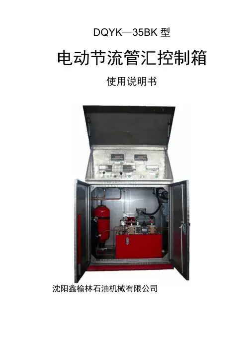
DJFK6型角阀控制器说明书沈阳鑫榆林石油机械有限公司DJFK6型角阀控制器说明书DJFK6型角阀控制器是孔板式液动节流阀上的专用变送器,它将节流阀的开度转换成4—20mA电信号输送给数字显示仪以显示阀的开度。
一、主要技术数据1、最大输出扭矩:150Kgf·m2、输入液压压力:6~8MPa3、测量范围:0°~180°4、精度等级:1.5级5、液路联接:快速接头M22×1.5二、结构与工作原理DJFK6型角阀控制器主要由液压驱动和电信号传感两部分组成。
液压驱动部分由液压缸,齿条和齿轮轴等组成,电信号传感部分由转换机构和位移变送器组成。
工作原理为液压缸推动齿条带动齿轮轴旋转,转动角度为0°~180°,由齿轮轴同步带动孔板式节流阀阀芯转动达到其开、关的目的,同时转换机构推动位移变送器直线移动,使其输出信号随之改变,从而在开度表上显示出孔板式节流阀的开度大小。
三、安装与使用DJFK6型角阀控制器与电动节流管汇控制箱配套使用,控制孔板式液动节流阀开或关,在控制箱面板上操纵手动换向阀通过角阀控制器来控制孔板式节流阀,同时数显表可显示孔板式节流阀的开度大小。
安装调试如结构示意图所示,用过渡接头将角阀控制器和孔板式节流阀阀杆联接起来,用4—M18螺栓通过联接板将角阀控制器固定在孔板式节流阀上。
再将油路管线和航空插头按标牌标定位置对应联接。
转换机构主要由位移变送器、触头、航空插件、调整螺钉等组成。
由于孔板式节流阀阀杆凸出长短不一致,每次安装角阀控制器时需精确对零调整,先将孔板式节流阀关闭,将角阀控制器安装在孔板式节流阀上,松动调整螺钉,移动位移变送器,使阀位数字显示仪读数为“0”,零位调整好后,紧定调整螺钉。
四、说明1、齿轮箱体内应每半年更换一次齿轮润滑机油。
2、联接板由需方自备。
3、过渡接头六角方尺寸依需方而定。
结 构 示 意 图位移变送器航空插头调整螺钉转换机构触头调整螺钉DJFK6 Type Angle Valve ControllerInstruction ManualShenyang Xinyulin Petroleum Machinery Co., Ltd. Instruction Manual for DJFK6 Type Angle Valve ControllerThe DJFK6 Type Angle Valve Controller, specially designed for the orifice plate hydrodynamic throttle valve, is used to convert valve opening into 4—20mA electrical signals and transmit them to the digital indicator so that the valve opening is displayed.1. Main technical details1) Maximum output torque: 150Kgf·m2) Input hydraulic pressure: 6~8MPa3) Range of measurement: 0°~180°4) Accuracy class: 1.55) Connection of hydraulic circuits: quick-acting coupling M22×1.52. Structure and operating principlesThe DJFK6 Type Angle Valve Controller is mainly composed of the hydraulic drive unit and the electrical signal sensing unit. The former consists of the hydraulic cylinder, rack and gear shaft, etc., and the later includes a converter and a displacement transmitter. Its operating principles are as follows: the hydraulic cylinder acts on the rack, which then drives the gear shaft to rotate with a rotation angle ranging from 0° to180°. The core of the orifice plate hydrodynamic throttle valve is synchronously driven by the gear shaft, thus realizing the open/close of the valve. At the same time, the converter drives the displacement transmitter to move along a straight line, making its output signals changed along with it, thus the opening of the orifice platehydrodynamic throttle valve is displayed on the opening position indicator.3. Installation and ApplicationThe DJFK6 Type Angle Valve Controller is designed to use together with an electric throttle manifold to control the orifice plate hydrodynamic throttle valve by operating the hand-directional valve on the control panel. At the same time, the digital indicator will display the opening of the orifice plate hydrodynamic throttle valve. Its installation and commissioning shall refer to the following schematic structural diagram. The process is as follows: connect the angle valve controller with the orifice plate throttle valve rod by using a transition joint, then fix the angle valve to the orifice plate throttle valve by means of a connecting plate fastened with a 4—M18 bolt, lastly, connect the oil way with the aviation plug at the place marked with a label plate.The converter is mainly composed of the displacement transmitter, contracts, aviation plug and adjusting screw, etc. Due to the uncertainty of the protruded length of the valve rod of the orifice plate throttle valve, an accurate zero adjustment is necessary each time the angle valve is installed. The process is as follows: with the orifice plate throttle valve closed, fix the angle valve controller to the orifice plate throttle valve, then slacken the adjusting bolt to move the displacement transmitter until the reading on the valve position digital indicator is zero. Tighten the adjusting bolt after the zero position is well adjusted.4. Notes1)The gear lube oil in the gear box should be replaced on a half-year basis.2)The connecting plate shall be provided by the demanders.3)The hexagonal dimension of the transition joint shall be at the request of the demanders.Schematic structural diagramcontractaviation plugadjusting screwDisplacement transmitterConverteradjusting screw。