18_45KW普乐特控制器说明书
- 格式:doc
- 大小:303.50 KB
- 文档页数:9
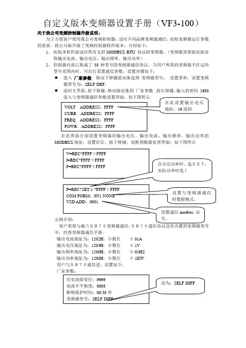
关于我公司变频控制器升级说明:
为了方便客户使用我公司变频控制器,适应不同品牌变频器通信,读取变频器运行参数的需求,我公司新升级了变频控制器软件版本,介绍如下:
1、 此版本软件能适应所有支持MODBUS RTU 协议的变频器。
(变频器需要能直接读取输出电流、输出电压、输出频率、输出功率)
2、 控制器内部已集成了38种型号的变频器通信协议,当用户所需的变频器不在这些型号范围内时,可自行设置通信参数。
设置步骤如下:
● 进入 厂家参数 移动下移键滚动条选到 变频器型号: 设置菜单,设置变频器型号为:SELF-DEF 。
● 返回主界面,按下移键,移动滚动条到 厂家参数 ,按右移键,输入的密码 2688
在此界面分别设置变频器的输出电压、输出电流、输出频率、输出功率的MODBUS 地址,设置好后,按下移键,切换到数据处理界面:如下图所示
客户需要与森兰SB70变频器通信,
SB70通信协议没有内置到变频器型号中,经查变频器通信手册。
输出电流地址为:1202H ,小数位 0.01A
输出电压地址为:1204H ,小数位 0.1V
输出频率地址为:1200H ,小数位 0.01HZ
输出功率地址为:1208H ,小数位 0.1KW
用户与SB70通信进,设置如下:
厂家参数:
返回主界面,按下移键,移动滚动条到厂家参数,按右移键,输入的密码2688,。
电脑控制器使用说明电脑控制器主要功能有监视压缩机运行状态,控制压缩机,保护压缩机,监控保养零件等。
电脑控制器是空压机的控制核心,对机组正常运行起关键作用,故请用户使用前详细阅读本控制器使用说明。
一、基本操作1、按键说明图1ON——起动键:按此键可起动电机运行OFF——停机键:按此键可停止电机运行M——设定键:修改完数据后,按此键确认数据存储输入❽——上移键:数据修改时,按此键上翻修改该数位;在菜单选择时作为选择键。
❾——下移键:数据修改时,按此键下翻修改该数位;在菜单选择时作为选择键。
❼——移位键/确认键:修改数据时,此键作为移位键;在菜单选择时作为确定键。
RT——返回键/复位键:在菜单操作时作为返回键返回上一级菜单;故障停机时,按此键复位。
2、状态显示与操作机组通电后显示如下界面:5秒后显示以下主界面:按“❾”进入以下菜单选择界面:a、运行参数查看按“❾”或“❽”移动黑色滚动条到“运行参数”菜单后,按确认键“❼”后弹出下一级菜单:再按“❼”弹出如为最后一级菜单,界面不会出现黑色滚动条,按返回键“RT”返回上级菜单或主界面。
如在某一界面停止操作,数秒钟后自动返回主界面。
用“❾”、“❽”移动键、确认键“❼”和返回键“RT”根据上述方法可完全观察到运行时间、本次运行时间、维护参数、历史故障、出厂日期、现场故障等运行参数并返回到上级菜单。
b、日历时间按“❾”或“❽”移动黑色滚动条到“日历”菜单后,按确认键“❼”后弹出在停机状态下可对日期、时间进行调整,操作方法为:按“❾”或“❽”移动黑色滚动条到需修改的参数项后按确定键“❼”后出现闪烁位,此时“❾”和“❽”键变为上翻和下翻键修改当前位,“❼”变为移位键移动修改位。
修改完毕后按“M”确认并保存,“❾”或“❽”变回移动黑色滚动条,“❼”变回返回键。
c、用户参数1)、参数修改方法══在运行状态和停机延时过程中不能修改用户参数和厂家参数══用前述运行参数查看的方法可查看和修改用户参数,如修改压力上限,操作方法如下:按“❾”或“❽”移动黑色滚动条到“用户参数”项后按确定键“❼”弹出再按确定键 “❼”弹出如不继续按确定键 “❼”即可查看用户参数。
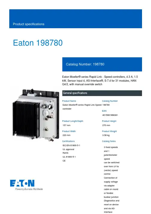
Eaton 198780Eaton Moeller® series Rapid Link - Speed controllers, 4.3 A, 1.5 kW, Sensor input 4, AS-Interface®, S-7.4 for 31 modules, HAN Q4/2, with manual override switchGeneral specificationsEaton Moeller® series Rapid Link Speed controller1987804015081968381157 mm 270 mm 220 mm 3.58 kg IEC/EN 61800-5-1 UL approval RoHS UL 61800-5-1 CEProduct NameCatalog NumberEANProduct Length/Depth Product Height Product Width Product Weight Certifications Catalog Notes 3 fixed speeds and 1 potentiometer speedcan be switched over from U/f to (vector) speed control Connection of supply voltage via adapter cable on round or flexible busbar junction Diagnostics and reset on device and via AS-InterfaceParameterization: FieldbusDiagnostics and reset on device and via AS-Interface Parameterization: drivesConnectParameterization: drivesConnect mobile (App) Parameterization: KeypadThermo-click with safe isolationControl unitInternal DC linkKey switch position HANDPC connectionSelector switch (Positions: REV - OFF - FWD)PTC thermistor monitoringTwo sensor inputs through M12 sockets (max. 150 mA) for quick stop and interlocked manual operationIGBT inverterManual override switchKey switch position AUTOKey switch position OFF/RESET3 fixed speeds1 potentiometer speed NEMA 12IP651st and 2nd environments (according to EN 61800-3)IIISpeed controllerASIAS-Interface profile cable: S-7.4 for 31 modulesC2, C3: depending on the motor cable length, the connected load, and ambient conditions. External radio interference suppression filters (optional) may be necessary.C1: for conducted emissions only2000 VCenter-point earthed star network (TN-S network)AC voltagePhase-earthed AC supply systems are not permitted.Vertical15 g, Mechanical, According to IEC/EN 60068-2-27, 11 ms, Half-sinusoidal shock 11 ms, 1000 shocks per shaftResistance: According to IEC/EN 60068-2-6Resistance: 57 Hz, Amplitude transition frequency on accelerationResistance: 10 - 150 Hz, Oscillation frequencyResistance: 6 Hz, Amplitude 0.15 mm Max. 2000 mAbove 1000 m with 1 % performance reduction per 100 m -10 °C40 °C-40 °C70 °CFeatures Fitted with:Functions Degree of protectionElectromagnetic compatibility Overvoltage categoryProduct categoryProtocolRadio interference classRated impulse withstand voltage (Uimp) System configuration typeMounting position Shock resistance Vibration AltitudeAmbient operating temperature - min Ambient operating temperature - max Ambient storage temperature - min Ambient storage temperature - max< 95 %, no condensation In accordance with IEC/EN 501780.4 - 4.3 A, motor, main circuit Adjustable, motor, main circuit < 10 ms, Off-delay < 10 ms, On-delay 98 % (η)4.1 A3.5 mA120 %Maximum of one time every 60 seconds 380 V480 V380 - 480 V (-10 %/+10 %, at 50/60 Hz)Synchronous reluctance motors U/f controlSensorless vector control (SLV) BLDC motors PM and LSPM motors 0 Hz500 HzAt 40 °CFor 60 s every 600 s6.5 AClimatic proofingCurrent limitationDelay timeEfficiency Input current ILN at 150% overload Leakage current at ground IPE - max Mains current distortion Mains switch-on frequencyMains voltage - min Mains voltage - max Mains voltage toleranceOperating modeOutput frequency - min Output frequency - max Overload current Overload current IL at 150% overload45 Hz66 Hz4.3 A at 150% overload (at an operating frequency of 8 kHz and an ambient air temperature of +40 °C)1.5 kW400 V AC, 3-phase480 V AC, 3-phase0.1 Hz (Frequency resolution, setpoint value)200 %, IH, max. starting current (High Overload), For 2 seconds every 20 seconds, Power section50/60 Hz8 kHz, 4 - 32 kHz adjustable, fPWM, Power section, Main circuitCenter-point earthed star network (TN-S network)AC voltagePhase-earthed AC supply systems are not permitted.2 HP≤ 0.6 A (max. 6 A for 120 ms), Actuator for external motor brakeAdjustable to 100 % (I/Ie), DC - Main circuit10 kAType 1 coordination via the power bus' feeder unit, Main circuit 24 V DC (-15 %/+20 %, external via AS-Interface® plug)AS-InterfacePlug type: HAN Q4/2Number of slave addresses: 31 (AS-Interface®) Specification: S-7.4 (AS-Interface®)Max. total power consumption from AS-Interface® power supply unit (30 V): 190 mARated frequency - minRated frequency - maxRated operational current (Ie)Rated operational power at 380/400 V, 50 Hz, 3-phase Rated operational voltageResolutionStarting current - maxSupply frequencySwitching frequencySystem configuration type Assigned motor power at 460/480 V, 60 Hz, 3-phase Braking currentBraking torqueRated conditional short-circuit current (Iq)Short-circuit protection (external output circuits) Rated control voltage (Uc)Communication interfaceConnectionInterfacesCable length10.2.2 Corrosion resistanceC2 ≤ 5 m, maximum motor cable length C3 ≤ 25 m, maximum motor cable length C1 ≤ 1 m, maximum motor cable length Meets the product standard's requirements.Meets the product standard's requirements.Meets the product standard's requirements.Meets the product standard's requirements.Meets the product standard's requirements.Does not apply, since the entire switchgear needs to be evaluated.Does not apply, since the entire switchgear needs to be evaluated.Meets the product standard's requirements.Does not apply, since the entire switchgear needs to be evaluated.Meets the product standard's requirements.Does not apply, since the entire switchgear needs to be evaluated.Does not apply, since the entire switchgear needs to be evaluated.Is the panel builder's responsibility.Is the panel builder's responsibility.Is the panel builder's responsibility.Is the panel builder's responsibility.10.2.3.1 Verification of thermal stability of enclosures10.2.3.2 Verification of resistance of insulating materials to normal heat10.2.3.3 Resist. of insul. mat. to abnormal heat/fire by internal elect. effects10.2.4 Resistance to ultra-violet (UV) radiation10.2.5 Lifting10.2.6 Mechanical impact10.2.7 Inscriptions10.3 Degree of protection of assemblies10.4 Clearances and creepage distances10.5 Protection against electric shock10.6 Incorporation of switching devices and components10.7 Internal electrical circuits and connections10.8 Connections for external conductors10.9.2 Power-frequency electric strength10.9.3 Impulse withstand voltage10.9.4 Testing of enclosures made of insulating materialIs the panel builder's responsibility.The panel builder is responsible for the temperature risecalculation. Eaton will provide heat dissipation data for the devices.Is the panel builder's responsibility. The specifications for the switchgear must be observed.Is the panel builder's responsibility. The specifications for the switchgear must be observed.The device meets the requirements, provided the information in the instruction leaflet (IL) is observed.Electromagnetic compatibility (EMC)Generation change RAMO4 to RAMO5Generation change from RA-SP to RASP 4.0Generation change from RA-MO to RAMO 4.0Generation Change RASP4 to RASP5Connecting drives to generator suppliesConfiguration to Rockwell PLC for Rapid LinkGeneration Change RA-SP to RASP5Rapid Link 5 - brochureDA-SW-drivesConnect USB Driver DX-COM-PCKITDA-SW-USB Driver DX-COM-STICK3-KITDA-SW-USB Driver PC Cable DX-CBL-PC-1M5DA-SW-drivesConnect - InstallationshilfeDA-SW-Driver DX-CBL-PC-3M0DA-SW-drivesConnectDA-SW-drivesConnect - installation helpMaterial handling applications - airports, warehouses and intra-logisticsProduct Range Catalog Drives EngineeringProduct Range Catalog Drives Engineering-ENDA-DC-00004514.pdfDA-DC-00003964.pdfDA-DC-00004508.pdfDA-DC-00004184.pdfeaton-bus-adapter-rapidlink-speed-controller-dimensions-003.eps eaton-bus-adapter-rapidlink-speed-controller-dimensions-004.eps eaton-bus-adapter-rapidlink-speed-controller-dimensions-002.eps eaton-bus-adapter-rapidlink-speed-controller-dimensions-005.epsETN.RASP5-4400A31-412R000S1.edzIL034085ZU10.10 Temperature rise10.11 Short-circuit rating10.12 Electromagnetic compatibility10.13 Mechanical functionApplication notesBrochuresCataloguesCertification reportsDrawingseCAD modelInstallation instructionsEaton Corporation plc Eaton House30 Pembroke Road Dublin 4, Ireland © 2023 Eaton. All rights reserved. Eaton is a registered trademark.All other trademarks areproperty of their respectiveowners./socialmediaRapid Link 5MN034004EN MZ040046_EN MN040003_EN ramo5_v24.dwg rasp5_v24.stpInstallation videos Manuals and user guides mCAD model。
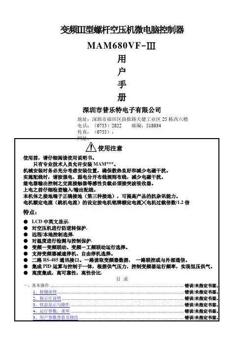
变频Ⅲ型螺杆空压机微电脑控制器MAM680VF-Ⅲ用户手册深圳市普乐特电子有限公司地址:深圳市福田区商报路天健工业区25栋西六楼电话:(0755)2822 邮编:518034传真:(0755):●LCD中英文显示.●对空压机进行防逆转保护.●远程/本地控制选择.●对温度进行检测与控制保护.●变频-变频联动、变频-工频联动运行选择。
●支持变频器减速停机、自由停机选择。
●二路RS-485通讯接口。
一路读取变频器数据,一路联控或与外部通信。
●集成PID运算与控制于一体,根据供气压力,控制变频器运行频率,实现恒压供气。
●高度集成,高可靠性,高性价比.目录一、基本操作...............................................................................1、按键说明...........................................................................2、指示灯说明.........................................................................3、状态显示与操作.....................................................................4、运行参数、菜单.....................................................................3、用户参数查看及修改.................................................................4、用户参数表及功能...................................................................4、厂家参数...........................................................................7、调整参数...........................................................................8、操作权限及密码管理.................................................................二、控制器功能及技术参数...................................................................三、型号规格...............................................................................四、安装...................................................................................1、机械安装.......................................................... 错误!未定义书签。
普乐特控制器设置说明普乐特控制器设置说明:1、系统需求在开始设置普乐特控制器之前,请确保您满足以下系统需求:- 操作系统: Windows 10 或更新版本- RAM:至少 2GB- 处理器:双核处理器- 硬盘空间:至少 200MB- 网络连接:可用的互联网连接2、控制器介绍普乐特控制器是一种专业的设备,用于控制和监控各种电气设备。
它具有以下主要特点:- 高度可定制的控制界面- 支持多种通信协议- 强大的报警功能- 实时数据监控和记录- 远程访问和控制功能3、安装和连接为了正确设置普乐特控制器,请按以下步骤进行:1、将控制器插入计算机的USB端口。
2、安装驱动程序,根据提供的说明进行操作。
3、打开控制器设置软件,并根据屏幕上的指引完成连接过程。
4、确保控制器成功连接并正常工作。
4、系统配置在设置普乐特控制器之前,请根据您的需求进行系统配置。
以下是一些可能需要配置的选项:- 设备名称和标识符- 网络连接设置- 通信协议和参数- 报警触发条件和通知方式- 数据记录和存储设置- 远程访问和控制权限5、监控和控制一旦完成配置,您可以开始使用普乐特控制器来监控和控制您的设备。
以下是一些建议的操作:- 实时监测数据:查看设备的实时数据,并随时更新。
- 报警管理:设置报警条件并配置通知方式,及时处理紧急情况。
- 远程访问:通过互联网远程访问和控制您的设备。
- 数据记录:启用数据记录功能,跟踪设备的历史数据。
- 配置管理:根据需要对配置进行修改和调整。
附件:本文档无附件。
法律名词及注释:1、控制器:指普乐特控制器,是一种用于控制和监控电气设备的专业设备。
2、通信协议:用于设备之间进行通信的规则和约定,以确保数据的传输和交换。
3、报警触发条件:指设定的一组条件,当这些条件满足时,系统会触发报警。
4、数据记录:记录设备的历史数据,包括各种参数和指标的变化记录。
5、远程访问:通过互联网远程连接和管理设备,无需直接接触设备。
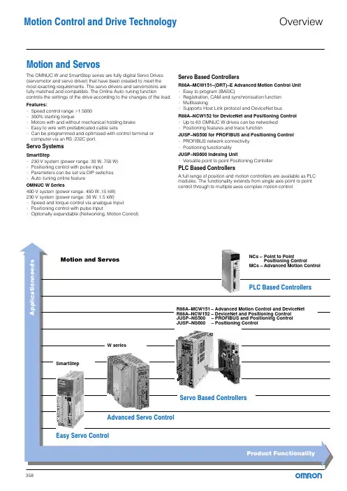
Motion and ServosThe OMNUC W and SmartStep series are fully digital Servo Drives (servomotor and servo driver) that have been created to meet the most exacting requirements. The servo drivers and servomotors are fully matched and compatible. The Online Auto−tuning function controls the settings of the drive according to the changes of the load. Features:−Speed control range >1:5000−300% starting torque−Motors with and without mechanical holding brake−Easy to wire with prefabricated cable sets−Can be programmed and optimised with control terminal or computer via an RS−232C port.Servo SystemsSmartStep−230 V system (power range: 30 W..750 W)−Positioning control with pulse input−Parameters can be set via DIP switches−Auto−tuning online featureOMNUC W Series400 V system (power range: 450 W..15 kW)230 V system (power range: 30 W..1.5 kW)−Speed and torque control via analogue Input−Positioning control with pulse input−Optionally expandable (Networking, Motion Control)Servo Based ControllersR88A–MCW151–(DRT)–E Advanced Motion Control Unit−Easy to program (BASIC)−Registration, CAM and synchronisation function−Multitasking−Supports Host Link protocol and DeviceNet busR88A–NCW152 for DeviceNet and Positioning Control−Up to 63 OMNUC W drives can be networked−Positioning features and trace functionJUSP–NS500 for PROFIBUS and Positioning Control−PROFIBUS network connectivity−Positioning functionalityJUSP–NS600 Indexing Unit−Versatile point to point Positioning ContollerPLC Based ControllersA full range of position and motion controllers are available as PLC modules. The functionality extends from single axis point to point control through to multiple axes complex motion controlMotion Control and Drive Technology OverviewThe SmartStep series has been designed to address the requirements of the low cost point−to−point motion market. These include fast response, accuracy and reliability. The SmartStep is an ideal alternative to stepper motors.The controller features Positioning Control with pulse input.The power range of this series ranges from 30 W..750 W, equivalent to 0.318..2.39 Nm of torque at 3000 rpm. The supply voltage is 230 V (50/60 Hz; single−phase).Characteristics:−Very compact design of motor and drive−Max. motor speed 4500 rpm, speed control range >1:5000−Rapid commissioning with the Online Autotune function−Motors available with and without mechanical holding brake−Parameters can also be set via DIP switches−300% acceleration torque−Easy to wire with prefabricated cable sets−Low weight−Convenient to operate from a control terminal−Computer programmable via RS−232CportSystem layout for simple positioning application.MotionandServosSystems without holding brake (3000 rpm motors)Systems with holding brake (3000 rpm motors)Encoder cable/motor cable without holding brake: R7A–CEAxxx–S Encoder cable/motor cable with holding brake: R7A–CEAxxx–B xxx = Cable length (see Accessories, page 364).SpecificationsCylindrical design motors without/with holding brakeSpecification for cylindrical design motors with holding brakeM o t i o n a n d S e r v o sCube design motors (without/with holding brake)Specification for cube design motors with holding brakeSmartStepM o t i o n a n d S e r v o sCables and Terminal block connections between SmartStep Servo drive and the PLC Positioning Control Unit. Without communications support.* 2 Terminal blocks and 2 Cables to the PLC are required for the C_W−NC4xx Units (4 axes).Cables and terminal block connections between SmartStep Servo drive and the PLC Positioning Control Unit.With communications support.blocks and 2 Cables to Other accessoriesProgramming and DocumentationProgrammingTechnicalDocumentationServo driver, 230 VLine filter, footprint, 230 VServomotors, cylindrical design (without brake), 230 VServomotors, cylindrical design (with brake), 230 VServomotors, cube design (without brake), 230 VServomotors, cube design (with brake), 230 VM o t i o n a n d S e r v o sMotion Control andMotion and Servos − SmartStep Drive TechnologyThe OMNUC W series is an advanced servo system designed to meet the demands of machine design. Motors and drives are fully matched and compatible. The optimum controller setting is continuously computed during operation by an online self−optimising function, so the servo always operates with maximum dynamics irrespective of load.The OMNUC W Series offers speed/torque and positioning control in a single unit. The servo drivers are available with a three−phase 400 V supply in a power range from 200 W..15 kW or single−phase 230 V supply in a power range from 30 W..1.5 kW.Characteristics:− All−in−One" compact controller with speed/torque and positioning control−Expandable with optional slot for positioning, advanced Motion control and networking−Motor protection class:200V class, IP55400V class, IP67, optional IP55−Speeds up to 6000 rpm−High resolution serial encoder, up to 17 bits−Extremely short cycle times for speed and position controller, producing maximum dynamicresponseExample of a system layout for simple motion control application with one CS1.MotionandServos230V classCylindrical design motorsSystems without holding brake (3000 rpm motors)Systems with holding brake (3000 rpm motors)Cube design motorsSystems without holding brake (3000 rpm motors)Systems with holding brake (3000 rpm motors)400V classCylindrical design motorsSystems without holding brake (1500 rpm motors)Systems with holding brake (1500 rpm motors)Systems without holding brake (3000 rpm motors)*Encoder cable for 300 and 650 W motors, R88A–CRWAxxxC–DE MotionandServos400V classSystems with holding brake (3000 rpm motors)*Encoder cable for 300 and 650 W motors, R88A–CRWAxxxC–DE A separate brake cable is not required for 300 and 650 W motors. Systems without holding brake (6000 rpm motors)Systems with holding brake (6000 rpm motors)Cube design motorsSystems without holding brake (3000 rpm motors)Systems with holding brake (3000 rpm motors)**Encoder cable for cube design motors, R88A–CRWAxxxC–DEA separate brake cable is not required for cube design motors.230V classServo driverType codingServomotors 200 VM o t i o n a n d S e r v o s230V classServomotor, rated speed 3000 rpm (cylindrical design)Servomotor, rated speed 3000 rpm (cube design)Motors with absolute encoder and special models are available. Please, contact your local Omron Office.400V classServo driver400V classServo driverType codingServomotors 400 VServomotor, rated speed 1500 rpm (cylindrical design)M o t i o n a n d S e r v o s400V classServomotor, rated speed 1500 rpm (cylindrical design)Servomotor, rated speed 3000 rpm (cylindrical design)400V classServomotor, rated speed 6000 rpm (cylindrical design)Servomotor, rated speed 3000 rpm (cube design)Motors with absolute encoder and special models are available. Please, contact your local Omron Office.MotionandServosfor Positioning ControlOMNUC Wfor Speed/Torque ControlM o t i o n a n d S e r v o sCable and Terminal block connections between OMNUC W Servo drive and te PLC Positioning Control Unit.* 2 Terminal blocks and 2 cables to the PLC are required for the C_W−NC4xx Units (4 axes).Cable and Terminal block connections between OMNUC W Servo drive and the PLC Motion Controller Units*The CS1W−MC421 Unit (4 axes) requires 2 cables.Cable and Terminal block connections between OMNUC W Servo drive and the Advanced Motion Controller Unit C200HW–MC402–EMotionandServosOther accessoriesOther accessoriesMotionandServosOther accessoriesDimensions (mm)Servo driver, 230 VLine filter, footprint, 230 VProgrammingTechnicalDocumentationServomotors, cylindrical design (without brake), 230 VServomotors, cylindrical design (with brake), 230 VServomotors, cube design (without brake), 230 VServomotors, cube design (with brake), 230 VServo driver, 400 VM o t i o na n d S e r v o sLine filter, footprint, 400 VServomotors, 1500 rpm, cylindrical design (without brake), 400 VServomotors, 3000 rpm, cylindrical design (without brake), 400 V*The 300 and 650 W motors have different connectors than shown in the pictureServomotors, 6000 rpm, cylindrical design (without brake), 400 VServomotors, 1500 rpm, cylindrical design (with brake), 400 VServomotors, 3000 rpm, cylindrical design (with brake), 400 V*The 300 and 650 W motors have different connectors than shown in the picture Servomotors, 6000 rpm, cylindrical design (with brake), 400 VServomotors, 3000 rpm, cube design (without brake), 400 VServomotors, 3000 rpm, cube design (with brake), 400 VM o t i o n a n d S e r v o sMotion Control andMotion and Servos − OMNUC W Drive TechnologyThe R88A−MCW151 is a 1.5 axis Motion Controller (MC) Unit that connects directly to the W series Servo Drive. The MC Unit provides direct control of the Servo Drive, enables position/speed and torque control, and offers access to detailed servo drive data.The Multitasking BASIC motion controller language is used to program the MC Unit. A total of up to 14 programs can be stored in the Unit, with up to 3 programs (tasks) running simultaneously. Motion Perfect is the powerful, user−friendly Windows−based software that facilitates highly flexible programming and troubleshooting.The MC Unit offers functionality including axes synchronisation, various fast registration inputs, electronic CAMs, interpolated movements and built−in general purpose inputs/outputs.The R88A−MCW151−DRT−E unit includes also DeviceNet connection, providing high systemintegration.MotionandServosProgramming Accessories, cables etc. Technical DocumentationM o t i o n a n d S e r v o sThe R88A−NCW152 provides both DeviceNet communication functions and the positioning functions of a positioning controller. These functions can be used very easily in conjunction with theW series servo drivers simply by plugging the Option Unit directly into the servo driver.With the NCW152 Unit it is possible to operate up to 63 W series servo drivers as DeviceNet slaves, allowing a widely distributed control and information management system to be created. The remote I/O commands support positioning commands, parameter read / write and the reading of monitor information. The trace function is available with explicit messages, enabling the user to monitor specific operation in detail and perform failure prediction and diagnostics.A large number of positioning functions are available, including zero search, point−to−point positioning, multi−speed, indexing, positioning by table entries and step positioning, feed function, backlash compensation and position−basedoutputs.MotionandServosProgrammingAccessories, cables etc.TechnicalDocumentationThe JUSP−NS500 provides PROFIBUS communications and positioning functionality. These functions can be added to a W−Series Servo Driver simply by mounting the option unit directly to it.With the PROFIBUS option unit it is possible to operate, from a PROFIBUS master, multiple W−Series Servo Drivers connected as PROFIBUS slaves. The commands from the host controller include positioning commands, reading alarm history and canceling commands.A variety of positioning functions are available including origin search, point−to−point positioning, point table and step positioning, feeding function, backslash compensation, and two zone signal outputs.MotionandServosProgrammingAccessories TechnicalDocumentationThe indexer unit JUSP−NS600 is a servo based positioning controller that connects directly to the W−series Servo Drive and provides direct control of the servo drive eliminating the need of an external axis controller.Easy setup and maintenance with the Windows based software tool, the system is configured using a fill−in−the−blank style settings and do not requires a specific language programming.The indexer unit enhances the W−series features with versatilepoint−to−point positioning, conditional profile execution in response to a registration input, definable zone signal outputs, built−in routines and settable positioning condition outputs. Control can be performed using the built−in I/O and via serial network commands.MotionandServos398Motion Control and Drive TechnologyIndexer Option UnitJUSP−NS600ProgrammingAccessoriesTechnicalDocumentation。

FLUKE 45 用户手册1.1一般性技术指标1.1.1检定周期为一年;1.1.2工作环境温度为18℃-28℃;1.1.3工作环境相对湿度不超过90%(非结露),电阻档1000kΩ以上量程相对湿度不超过70%。
精度表达形式为:±(读数%+字)2.1直流电压:2.2真有效值交流电压:2.3直流电流:2.4交流电流:2.5电阻:2.6频率:3 FLUKE-45 数字式多用表操作规范3.1使用多用表前的准备:3.1.1连接电源线,并按下电源开关,此时数表开机自检,前面板的显示器点亮,开机后,多用表将自动处于直流电压测试功能状态,自动量程有效。
3.1.2多用表使用前应预热,从开机到测试至少预热30分钟,以使内部各零件处于稳定状态,关机后重新开机需再预热,时间应大于两倍关机时间(最多30分钟)。
3.2用多用表进行测量:FLUKE-45数字式多用表进行电压、电流、电阻、频率等参数测量的步骤、方法及操作参见《FLUKE-45使用说明》。
测量中一般选用数表的自动量程转换功能,以免应误操作而损坏设备。
3.3使用后的注意事项:3.3.1测量结束应拔下测试线(表笔)妥善放置,以免下次测量时,因测量功能与输入插孔不对应而烧毁仪表。
3.3.2测量结束后关闭电源开关并拔去电源线,以防意外造成损坏。
4功能操作详解5使用比较功能比较功能(COMP)提供了一条简而易行的方法判别测量值是否超出了确定范围。
在比较模式下,仪器在主显示显示测量值,而在第二显示指示该值是高(HI),低(LO),抑或正好(PASS)落在确定范围内。
比较功能可用在很多测量功能中,例如:REL、MN MX、HOLD、和dB。
在使用该功能前,先要设定好用于比较的允许范围的最高和最低点数值,方法有三:* 可通过按下"2ND"键后,按"/\" (HI)或"\/" (LO)键来确定比较范围,此时显示的值将成为高(低)点界限值。
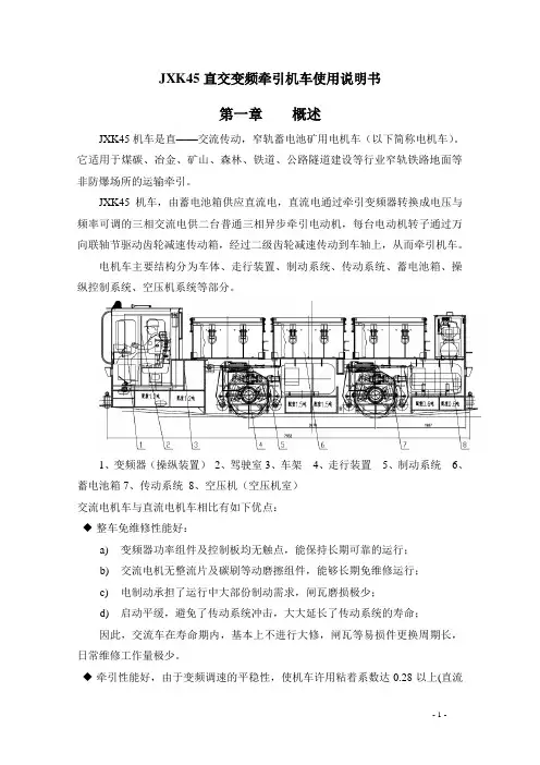
JXK45直交变频牵引机车使用说明书第一章概述JXK45机车是直——交流传动,窄轨蓄电池矿用电机车(以下简称电机车)。
它适用于煤碳、冶金、矿山、森林、铁道、公路隧道建设等行业窄轨铁路地面等非防爆场所的运输牵引。
JXK45机车,由蓄电池箱供应直流电,直流电通过牵引变频器转换成电压与频率可调的三相交流电供二台普通三相异步牵引电动机,每台电动机转子通过万向联轴节驱动齿轮减速传动箱,经过二级齿轮减速传动到车轴上,从而牵引机车。
电机车主要结构分为车体、走行装置、制动系统、传动系统、蓄电池箱、操纵控制系统、空压机系统等部分。
1、变频器(操纵装置)2、驾驶室3、车架4、走行装置5、制动系统6、蓄电池箱7、传动系统8、空压机(空压机室)交流电机车与直流电机车相比有如下优点:◆整车免维修性能好:a)变频器功率组件及控制板均无触点,能保持长期可靠的运行;b)交流电机无整流片及碳刷等动磨擦组件,能够长期免维修运行;c)电制动承担了运行中大部份制动需求,闸瓦磨损极少;d)启动平缓,避免了传动系统冲击,大大延长了传动系统的寿命;因此,交流车在寿命期内,基本上不进行大修,闸瓦等易损件更换周期长,日常维修工作量极少。
◆牵引性能好,由于变频调速的平稳性,使机车许用粘着系数达0.28以上(直流车0.2)。
交流车以同样的粘重可牵引比直流车大1/3的荷载,同时在加速过程中轮子不易打滑,保证了牵引的可靠性。
机车在50HZ频率以下电机为恒转距特性, 在50HZ频率以上电机为恒功率特性,使得机车的速度控制与运行工况对速度控制的需求十分吻合,因此交流车牵引十分可靠和稳定,可控制性良好。
◆制动性能好,需要制动时,变频器能够使交流电机从电动机状态转变为发电机状态,通过传动系统对行走轮进行制动,即电制动。
电制动的工况特性与牵引工况特性完全相同,因此,电制动具有与牵引同样的可靠性和有效性。
制动操作十分简单,系统反应快于直流车,并且不存在机件磨擦磨损,因此,交流车的制动能力、性能上优于直流车。
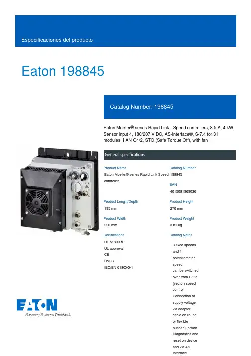
Eaton 198845Eaton Moeller® series Rapid Link - Speed controllers, 8.5 A, 4 kW, Sensor input 4, 180/207 V DC, AS-Interface®, S-7.4 for 31 modules, HAN Q4/2, STO (Safe Torque Off), with fanGeneral specificationsEaton Moeller® series Rapid Link Speed controller1988454015081969036195 mm 270 mm 220 mm 3.61 kg UL 61800-5-1 UL approval CE RoHSIEC/EN 61800-5-1Product NameCatalog NumberEANProduct Length/Depth Product Height Product Width Product Weight Certifications Catalog Notes 3 fixed speeds and 1 potentiometer speedcan be switched over from U/f to (vector) speed control Connection of supply voltage via adapter cable on round or flexible busbar junction Diagnostics and reset on device and via AS-Interface480 VIs the panel builder's responsibility. The specifications for the switchgear must be observed.400 V AC, 3-phase480 V AC, 3-phaseMeets the product standard's requirements.4 kW500 VMeets the product standard's requirements.-40 °C380 VSelector switch (Positions: REV - OFF - FWD)Control unitPC connectionTwo sensor inputs through M12 sockets (max. 150 mA) for quick stop and interlocked manual operationKey switch position OFF/RESETFanKey switch position HANDIGBT inverterKey switch position AUTOThermo-click with safe isolationInternal DC linkPTC thermistor monitoring0 Hz200 %, IH, max. starting current (High Overload), For 2 seconds every 20 seconds, Power section eaton-bus-adapter-rapidlink-speed-controller-dimensions-004.eps eaton-bus-adapter-rapidlink-speed-controller-dimensions-003.eps eaton-bus-adapter-rapidlink-speed-controller-dimensions-002.eps eaton-bus-adapter-rapidlink-speed-controller-dimensions.epsETN.RASP5-8401A31-4120011S1.edzRapid Link 5 - brochureDA-SW-drivesConnectDA-SW-USB Driver DX-COM-STICK3-KITDA-SW-USB Driver PC Cable DX-CBL-PC-1M5DA-SW-drivesConnect - installation helpDA-SW-Driver DX-CBL-PC-3M0DA-SW-drivesConnect - InstallationshilfeMaterial handling applications - airports, warehouses and intra-logisticsIL034085ZUramo5_v28.dwgrasp5_v28.stpGeneration Change RA-SP to RASP5Generation change from RA-MO to RAMO 4.0Generation change RAMO4 to RAMO5Generation Change RASP4 to RASP5Configuration to Rockwell PLC for Rapid LinkGeneration change from RA-SP to RASP 4.0DA-DC-00003964.pdfDA-DC-00004184.pdfDA-DC-00004613.pdfDA-DC-00004612.pdfMains voltage - max10.11 Short-circuit ratingRated operational voltage10.4 Clearances and creepage distancesOutput at quadratic load at rated output voltage - max Output voltage - max10.2.3.1 Verification of thermal stability of enclosures Ambient storage temperature - minMains voltage - minFitted with:Output frequency - minStarting current - max DibujoseCAD modelFolletosInstrucciones de instalación mCAD modelNotas de aplicación Reportes de certificacionesRated conditional short-circuit current (Iq)10 kAAmbient operating temperature - max40 °CCommunication interfaceAS-InterfaceAssigned motor power at 115/120 V, 60 Hz, 1-phase5 HPOutput frequency - max500 HzSwitching frequency8 kHz, 4 - 32 kHz adjustable, fPWM, Power section, Main circuitFeaturesParameterization: drivesConnect mobile (App) Parameterization: drivesConnectDiagnostics and reset on device and via AS-Interface Parameterization: KeypadInternal and on heat sink, temperature-controlled Fan Parameterization: FieldbusAmbient operating temperature - min-10 °CBraking current≤ 0.6 A (max. 6 A for 120 ms), Actuator for external motor brakeNumber of HW-interfaces (serial TTY)10.6 Incorporation of switching devices and componentsDoes not apply, since the entire switchgear needs to be evaluated.Nominal output current I2N8.5 A10.2.6 Mechanical impactDoes not apply, since the entire switchgear needs to be evaluated.10.3 Degree of protection of assembliesDoes not apply, since the entire switchgear needs to be evaluated.Product categorySpeed controllerRadio interference classC1: for conducted emissions onlyC2, C3: depending on the motor cable length, the connected load, and ambient conditions. External radio interference suppression filters (optional) may be necessary.Heat dissipation capacity Pdiss0 WRated control voltage (Uc)180/207 V DC (external brake 50/60 Hz)24 V DC (-15 %/+20 %, external via AS-Interface® plug)Assigned motor power at 460/480 V, 60 Hz, 3-phase5 HPNumber of HW-interfaces (RS-422)Mains current distortion120 %ProtocolASIAS-Interface profile cable: S-7.4 for 31 modules10.9.2 Power-frequency electric strengthIs the panel builder's responsibility.Overvoltage categoryIIIDegree of protectionNEMA 12IP65Ambient storage temperature - max70 °CRated impulse withstand voltage (Uimp)2000 VConnectionPlug type: HAN Q4/2Overload currentAt 40 °CFor 60 s every 600 sFunctions3 fixed speedsSTO (Safe Torque Off)For actuation of motors with mechanical brake1 potentiometer speedOutput at linear load at rated output voltage - max4 kWMains voltage tolerance380 - 480 V (-10 %/+10 %, at 50/60 Hz)Leakage current at ground IPE - max3.5 mAConverter typeU converter10.2.2 Corrosion resistanceMeets the product standard's requirements.Supply frequency50/60 Hz10.2.4 Resistance to ultra-violet (UV) radiationMeets the product standard's requirements.10.2.7 InscriptionsMeets the product standard's requirements.Shock resistance15 g, Mechanical, According to IEC/EN 60068-2-27, 11 ms, Half-sinusoidal shock 11 ms, 1000 shocks per shaftApplication in domestic and commercial area permittedYesNumber of inputs (analog)Number of phases (output)310.12 Electromagnetic compatibilityIs the panel builder's responsibility. The specifications for the switchgear must be observed.10.2.5 LiftingDoes not apply, since the entire switchgear needs to be evaluated.Number of HW-interfaces (RS-485)1Number of HW-interfaces (industrial ethernet)Efficiency98 % (η)System configuration typeAC voltageCenter-point earthed star network (TN-S network)Phase-earthed AC supply systems are not permitted.10.8 Connections for external conductorsIs the panel builder's responsibility.ProtectionFinger and back-of-hand proof, Protection against direct contact (BGV A3, VBG4)Braking voltage280/207 V DC -15 % / +10 %, Actuator for external motor brakeApplication in industrial area permittedYesClimatic proofing< 95 %, no condensationIn accordance with IEC/EN 5017810.9.3 Impulse withstand voltageIs the panel builder's responsibility.Overload current IL at 150% overload12.7 AInput current ILN at 150% overload7.8 ANumber of HW-interfaces (RS-232)Number of inputs (digital)4Current limitationAdjustable, motor, main circuit0.8 - 8.5 A, motor, main circuitCable lengthC1 ≤ 1 m, maximum motor cable lengthC2 ≤ 5 m, maximum motor cable lengthC3 ≤ 25 m, maximum motor cable length10.5 Protection against electric shockDoes not apply, since the entire switchgear needs to be evaluated.Mounting positionVerticalMains switch-on frequencyMaximum of one time every 60 seconds10.13 Mechanical functionThe device meets the requirements, provided the information in the instruction leaflet (IL) is observed.10.9.4 Testing of enclosures made of insulating materialIs the panel builder's responsibility.Heat dissipation per pole, current-dependent Pvid0 WElectromagnetic compatibility1st and 2nd environments (according to EN 61800-3)Resolution0.1 Hz (Frequency resolution, setpoint value)Assigned motor power at 460/480 V, 60 Hz5 HPRelative symmetric net voltage tolerance10 %Rated operational current (Ie)8.5 A at 150% overload (at an operating frequency of 8 kHz and an ambient air temperature of +40 °C)Number of outputs (analog)Rated operational power at 380/400 V, 50 Hz, 3-phase4 kWNumber of HW-interfaces (USB)Operating modeSynchronous reluctance motorsU/f controlBLDC motorsSensorless vector control (SLV)PM and LSPM motorsRated frequency - min45 HzDelay time< 10 ms, Off-delay< 10 ms, On-delayNumber of outputs (digital)Power consumption95 W10.2.3.2 Verification of resistance of insulating materials to normal heatMeets the product standard's requirements.10.2.3.3 Resist. of insul. mat. to abnormal heat/fire by internal elect. effectsMeets the product standard's requirements.Number of HW-interfaces (other)1Rated frequency - max66 HzVibrationResistance: 10 - 150 Hz, Oscillation frequencyResistance: 6 Hz, Amplitude 0.15 mmResistance: According to IEC/EN 60068-2-6Resistance: 57 Hz, Amplitude transition frequency on accelerationShort-circuit protection (external output circuits)Type 1 coordination via the power bus' feeder unit, Main circuit10.7 Internal electrical circuits and connectionsIs the panel builder's responsibility.Braking torque≤ 30 % (I/Ie)Adjustable to 100 % (I/Ie), DC - Main circuitRelative symmetric net frequency tolerance10 %10.10 Temperature riseThe panel builder is responsible for the temperature rise calculation. Eaton will provide heat dissipation data for the devices.Number of HW-interfaces (parallel)Assigned motor power at 230/240 V, 60 Hz, 1-phase5 HPInterfacesNumber of slave addresses: 31 (AS-Interface®)Max. total power consumption from AS-Interface® power supply unit (30 V): 190 mASpecification: S-7.4 (AS-Interface®)Eaton Corporation plc Eaton House30 Pembroke Road Dublin 4, Ireland © 2023 Eaton. Todos los derechos reservados. Eaton is a registered trademark.All other trademarks areproperty of their respectiveowners./socialmedia351.6 W at 25% current and 0% speed 53.8 W at 25% current and 50% speed 60.9 W at 50% current and 0% speed 64 W at 50% current and 90% speed 65.4 W at 50% current and 50% speed 85.1 W at 100% current and 0% speed 94 W at 100% current and 50% speed 95.3 W at 100% current and 90% speed 0Above 1000 m with 1 % performance reduction per 100 m Max. 2000 mNumber of phases (input)Heat dissipation at current/speed Number of interfaces (PROFINET)Altitude。
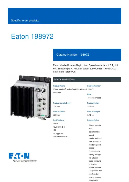
Eaton 198972Eaton Moeller® series Rapid Link - Speed controllers, 4.3 A, 1.5 kW, Sensor input 4, Actuator output 2, PROFINET, HAN Q4/2, STO (Safe Torque Off)General specificationsEaton Moeller® series Rapid Link Speed controller1989724015081970308157 mm 270 mm 220 mm 3.45 kg RoHS UL 61800-5-1 CE UL approval IEC/EN 61800-5-1Product NameCatalog NumberEANProduct Length/Depth Product Height Product Width Product Weight Certifications Catalog Notes 3 fixed speeds and 1 potentiometer speedcan be switched over from U/f to (vector) speed control Connection of supply voltage via adapter cable on round or flexible busbar junction Diagnostics and reset on the device and via PROFINETParameterization: drivesConnect mobile (App) Parameterization: drivesConnectParameterization: KeypadParameterization: FieldbusKey switch position OFF/RESETKey switch position HANDIGBT inverterPC connectionKey switch position AUTOTwo sensor inputs through M12 sockets (max. 150 mA) for quick stop and interlocked manual operationPTC thermistor monitoringThermo-click with safe isolationSelector switch (Positions: REV - OFF - FWD)2 Actuator outputsControl unitInternal DC link3 fixed speedsSTO (Safe Torque Off)1 potentiometer speed IP65NEMA 121st and 2nd environments (according to EN 61800-3)IIISpeed controllerPROFINET IOC2, C3: depending on the motor cable length, the connected load, and ambient conditions. External radio interference suppression filters (optional) may be necessary.C1: for conducted emissions only2000 VAC voltageCenter-point earthed star network (TN-S network)Phase-earthed AC supply systems are not permitted.Vertical15 g, Mechanical, According to IEC/EN 60068-2-27, 11 ms, Half-sinusoidal shock 11 ms, 1000 shocks per shaftResistance: 10 - 150 Hz, Oscillation frequencyResistance: According to IEC/EN 60068-2-6Resistance: 6 Hz, Amplitude 0.15 mmResistance: 57 Hz, Amplitude transition frequency on acceleration Max. 2000 mAbove 1000 m with 1 % performance reduction per 100 m -10 °C40 °C-40 °C70 °CFeatures Fitted with:Functions Degree of protectionElectromagnetic compatibility Overvoltage categoryProduct categoryProtocolRadio interference classRated impulse withstand voltage (Uimp) System configuration typeMounting position Shock resistance Vibration AltitudeAmbient operating temperature - min Ambient operating temperature - max Ambient storage temperature - min Ambient storage temperature - max Climatic proofing< 95 %, no condensationIn accordance with IEC/EN 50178Current limitationAdjustable, motor, main circuit0.4 - 4.3 A, motor, main circuitDelay time< 10 ms, On-delay< 10 ms, Off-delayEfficiency98 % (η)Input current ILN at 150% overload4.1 ALeakage current at ground IPE - max3.5 mAMains current distortion120 %Mains switch-on frequencyMaximum of one time every 60 secondsMains voltage - min380 VMains voltage - max480 VMains voltage tolerance380 - 480 V (-10 %/+10 %, at 50/60 Hz)Operating modeU/f controlSynchronous reluctance motorsSensorless vector control (SLV)BLDC motorsPM and LSPM motorsOutput frequency - min0 HzOutput frequency - max500 HzOverload currentFor 60 s every 600 sAt 40 °COverload current IL at 150% overload6.5 A45 Hz66 Hz1.5 kW400 V AC, 3-phase480 V AC, 3-phase0.1 Hz (Frequency resolution, setpoint value)200 %, IH, max. starting current (High Overload), For 2 seconds every 20 seconds, Power section50/60 Hz8 kHz, 4 - 32 kHz adjustable, fPWM, Power section, Main circuitAC voltageCenter-point earthed star network (TN-S network)Phase-earthed AC supply systems are not permitted.2 HP≤ 0.6 A (max. 6 A for 120 ms), Actuator for external motor brakeAdjustable to 100 % (I/Ie), DC - Main circuit10 kAType 1 coordination via the power bus' feeder unit, Main circuit 24 V DC (-15 %/+20 %, external via AS-Interface® plug)PROFINET, optionalPlug type: HAN Q4/2Specification: S-7.4 (AS-Interface®)Max. total power consumption from AS-Interface® power supply unit (30 V): 250 mANumber of slave addresses: 31 (AS-Interface®)C1 ≤ 1 m, maximum motor cable length C2 ≤ 5 m, maximum motor cable length C3 ≤ 25 m, maximum motor cable lengthMeets the product standard's requirements. Meets the product standard's requirements.Rated frequency - minRated frequency - maxRated operational power at 380/400 V, 50 Hz, 3-phase Rated operational voltageResolutionStarting current - maxSupply frequencySwitching frequencySystem configuration type Assigned motor power at 460/480 V, 60 Hz, 3-phase Braking currentBraking torqueRated conditional short-circuit current (Iq)Short-circuit protection (external output circuits) Rated control voltage (Uc)Communication interfaceConnectionInterfacesCable length10.2.2 Corrosion resistance10.2.3.1 Verification of thermal stability of enclosures10.2.3.2 Verification of resistance of insulating materials tonormal heatMeets the product standard's requirements.Meets the product standard's requirements.Meets the product standard's requirements.Does not apply, since the entire switchgear needs to be evaluated.Does not apply, since the entire switchgear needs to be evaluated.Meets the product standard's requirements.Does not apply, since the entire switchgear needs to be evaluated.Meets the product standard's requirements.Does not apply, since the entire switchgear needs to be evaluated.Does not apply, since the entire switchgear needs to be evaluated.Is the panel builder's responsibility.Is the panel builder's responsibility.Is the panel builder's responsibility.Is the panel builder's responsibility.Is the panel builder's responsibility.The panel builder is responsible for the temperature rise calculation. Eaton will provide heat dissipation data for the devices.Rapid Link 5 - brochureDA-SW-drivesConnectDA-SW-USB Driver DX-COM-STICK3-KITDA-SW-drivesConnect - InstallationshilfeDA-SW-Driver DX-CBL-PC-3M0DA-SW-USB Driver PC Cable DX-CBL-PC-1M5DA-SW-drivesConnect - installation helpMaterial handling applications - airports, warehouses and intra-logisticseaton-bus-adapter-rapidlink-speed-controller-dimensions.epseaton-bus-adapter-rapidlink-speed-controller-dimensions-002.eps eaton-bus-adapter-rapidlink-speed-controller-dimensions-004.eps eaton-bus-adapter-rapidlink-speed-controller-dimensions-003.epsETN.RASP5-4420PNT-4120010S1.edzIL034093ZUrasp5_v39.stpramo5_v39.dwgConfiguration to Rockwell PLC for Rapid LinkGeneration Change RA-SP to RASP5Generation change from RA-MO to RAMO 4.0Generation Change RASP4 to RASP5Generation change from RA-SP to RASP 4.0Generation change RAMO4 to RAMO5DA-DC-00004184.pdfDA-DC-00004612.pdfDA-DC-00003964.pdfDA-DC-00004613.pdf10.2.3.3 Resist. of insul. mat. to abnormal heat/fire by internalelect. effects10.2.4 Resistance to ultra-violet (UV) radiation10.2.5 Lifting10.2.6 Mechanical impact10.2.7 Inscriptions10.3 Degree of protection of assemblies10.4 Clearances and creepage distances10.5 Protection against electric shock10.6 Incorporation of switching devices and components 10.7 Internal electrical circuits and connections10.8 Connections for external conductors10.9.2 Power-frequency electric strength10.9.3 Impulse withstand voltage10.9.4 Testing of enclosures made of insulating material 10.10 Temperature rise BrochureDisegnieCAD modelIstruzioni di installazione mCAD modelNote per l'applicazione Report di certificazioneEaton Corporation plc Eaton House30 Pembroke Road Dublin 4, Ireland © 2023 Eaton. Tutti i diritti riservati. Eaton is a registered trademark.All other trademarks areproperty of their respectiveowners./socialmediaIs the panel builder's responsibility. The specifications for the switchgear must be observed.Is the panel builder's responsibility. The specifications for the switchgear must be observed.The device meets the requirements, provided the information in the instruction leaflet (IL) is observed.10.11 Short-circuit rating10.12 Electromagnetic compatibility10.13 Mechanical function。
MAM6090节能机微电脑控制器用户手册深圳市普乐特电子有限公司地址:深圳市坂田岗头好时达工业区5栋4、5楼电话:(0755)83172098 83172822 邮编:518129传真:(0755)83172966 E-mail:plt@网址:感谢非常感谢您选择深圳市普乐特电子有限公司生产的空压机控制器。
深圳市普乐特有限公司专注从事空压机控制器领域的生产及研发制造,致力于用高质量的产品、优质的服务赢得客户的信任。
我们将尽量保证手册的完整性和准确性,但普乐特公司将保留产品不断研发和改进的权利而不负有对以前出厂的产品进行修改和改进的义务,当产品设计变更时将不再另行通知。
如果您在使用我们机器的过程中遇到了任何问题,请与我司及时联系。
欢迎您随时提出宝贵意见!特点:●支持多种机型选择。
● 7 寸彩屏显示,带键盘与触摸功能。
●支持实时用电量与累计用电量测量。
●带定时启停功能选择,定时压力功能选择。
●控制变频器,采用485通信写频,控制更精准。
●可控制任意支持MODBUS RTU协议变频器,选择更灵活。
●对电机具有缺相、过载、不平衡、电压过高、电压过低保护功能.●高度集成,高可靠性,高性价比.目录一、基本操作 (6)1.1 按键说明 (6)1.2指示灯说明 (8)1.3状态显示与操作 (8)1.4 运行参数 (9)1.5用户参数 (11)1.6厂家参数 (13)1.7校准参数 (14)1.8联控参数 (15)1.9硬件参数 (16)1.10耗材参数 (16)1.11变频器预置 (17)1.12屏校准 (18)1.13定时压力 (18)1.14定时启停 (19)1.15历史故障 (19)1.16主机变频 (19)1.17风机变频 (21)1.18日期时间 (22)1.19操作权限及密码管理 (22)二、控制器功能及技术参数 (23)三、型号规格 (24)3.1型号说明 (24)3.2适用电机功率规格表 (24)四、安装 (24)4.1 互感器安装 (24)4.2控制器安装 (25)五、预警功能 (28)5.1空滤器预警 (28)5.2油滤器预警 (28)5.3油分器预警 (28)5.4润滑油使用时间预警 (28)5.5润滑脂使用时间预警 (28)5.6排气温度高预警 (28)六、安全保护 (28)6.1对电机的保护 (28)6.2排气超温保护 (29)6.3空压机防逆转保护 (29)6.4空压机防断相保护 (29)6.5供气压力超压保护 (29)6.6传感器失灵保护 (29)七、常见故障的处理 (29)八、联动控制、联网通信 (30)8.1联控说明: (30)8.2联网通信 (30)九、控制变频器运行 (31)十、电气接线图 (33)10.1工频 (33)10.2工变频切换 (34)10.3风机变频 (35)10.4主、风机变频 (36)10.5软启动 (37)一、基本操作1.1 按键说明图1.1.1数据显示与修改输入框参数设置与显示按键换页按钮——启动键:¾空压机处于待机状态时,按此键可启动空压机运行;¾通信方式设为联动,且通讯地址为1时,按此键,启动空压机运行,同时启动联动控制功能。
螺杆空压机微电脑控制器MAM-KY02S(B)-(Ⅷ)型(中文液晶显示-100)用户手册深圳市普乐特电子有限公司地址:深圳市福田区商报路天健工业区25栋西六楼电话:(0755)83172098 83172068 邮编:518034传真:(0755)83172966 E-mail:plt@网址:特点:●LCD中英文显示●对电机具有短路、堵转、缺相、过载、不平衡等全方位保护功能●对电机具有起停控制、运行控制●对空压机进行防逆转保护●对多点温度进行检测与控制保护●自动调节负荷率控制压力平衡●高度集成,高可靠性,高性价比●远程/机旁选择控制●联动/独立选择运行●RS-485通讯功能一、基本操作1、按键说明图18ON——起动键:按此键可起动电机运行OFF——停机键:按此键可停止电机运行M——设定键:修改完数据后,按此键确认数据存储输入❽——上移键:数据修改时,按此键上翻修改该数位;在菜单选择时作为选择键。
❾——下移键:数据修改时,按此键下翻修改该数位;在菜单选择时作为选择键。
❼——移位键/确认键:修改数据时,此键作为移位键;在菜单选择时作为确定键。
RT——返回键/复位键:在菜单操作时作为返回键返回上一级菜单;故障停机时,按此键复位。
2、状态显示与操作机组通电后显示如下界面:5秒后显示以下主界面:按“❾”进入以下菜单选择界面:a、运行参数查看按“❾”或“❽”移动黑色滚动条到“运行参数”菜单后,按确认键“❼”后弹出下一级菜单:再按“❼”弹出如为最后一级菜单,界面不会出现黑色滚动条,按返回键“RT”返回上级菜单或主界面。
如在某一界面停止操作,数秒钟后自动返回主界面。
用“❾”、“❽”移动键、确认键“❼”和返回键“RT”根据上述方法可完全观察到运行时间、本次运行时间、维护参数、历史故障、出厂日期、现场故障等运行参数并返回到上级菜单。
b、日历时间按“❾”或“❽”移动黑色滚动条到“日历”菜单后,按确认键“❼”后弹出在停机状态下可对日期、时间进行调整,操作方法为:按“❾”或“❽”移动黑色滚动条到需修改的参数项后按确定键“❼”后出现闪烁位,此时“❾”和“❽”键变为上翻和下翻键修改当前位,“❼”变为移位键移动修改位。
uprekb-45控制与保护开关说明书摘要:I.引言- 控制与保护开关的简介- 控制与保护开关在电力系统中的应用II.产品概述- 控制与保护开关的型号和规格- 控制与保护开关的主要功能和特点III.工作原理- 控制与保护开关的工作原理- 控制与保护开关的保护功能IV.安装与使用- 控制与保护开关的安装要求- 控制与保护开关的使用方法V.维护与保养- 控制与保护开关的维护方法- 控制与保护开关的保养建议VI.结论- 控制与保护开关在电力系统中的重要性- 控制与保护开关的未来发展趋势正文:引言控制与保护开关是电力系统中一种重要的保护装置,主要用于接通、承载和分断正常条件下的电流或电压,同时也能够接通、承载一定时间和分断规定的非正常条件下的电流或电压。
在电力系统中,控制与保护开关能够有效地保护电力设备,防止电力系统的故障,确保电力系统的稳定运行。
产品概述控制与保护开关型号为uprekb-45,具有多种规格,能够满足不同电力系统的需求。
该型号的控制与保护开关具有以下几个主要功能和特点:1.短路保护:控制与保护开关能够在短路条件下迅速切断电流,保护电力设备不受损坏。
2.过载保护:控制与保护开关能够在过载条件下自动切断电流,防止电力设备过热损坏。
3.负载控制:控制与保护开关能够根据电力系统的负载情况,自动调节电流大小,保证电力系统的稳定运行。
4.操作简单:控制与保护开关操作简单,使用方便,能够大大提高电力系统的运行效率。
工作原理控制与保护开关的工作原理是,当电力系统中的电流或电压超过设定值时,控制与保护开关会自动切断电流或电压,防止电力设备受到损坏。
控制与保护开关的保护功能能够有效地保护电力系统的安全运行。
安装与使用控制与保护开关的安装要求如下:1.控制与保护开关应安装在干燥、通风、无腐蚀气体和无爆炸危险的环境中。
2.控制与保护开关的安装位置应便于操作和维护。
3.控制与保护开关的接线应正确、牢固,并符合相关标准。
螺杆空压机微电脑控制器MAM-KY02S(B)-(Ⅷ)型(中文液晶显示-100)用户手册深圳市普乐特电子有限公司地址:深圳市坂田岗头好时达工业区5栋4、5楼电话:(0755)83172098 83172822 邮编:518129传真:(0755)83172966 E-mail:plt@网址:感谢非常感谢您选择深圳市普乐特电子公司生产的空压机控制器。
深圳市普乐特公司专注从事空压机控制器领域的生产及研发制造,致力于用高质量的产品,优质的服务赢得客户的信任。
我们将尽量保证手册的完整性和准确性,但普乐特公司将保留产品不断研发和改进的权利而不负有对以前出厂的产品进行修改和改进的义务,当产品设计变更时将不再另行通知。
如果您在使用我们机器的过程中遇到了任何问题,请与我司服务技术中心及时的取得联系。
欢迎您随时提出宝贵意见!使用注意特点:● LCD中英文显示● 对电机具有短路、堵转、缺相、过载、不平衡等全方位保护功能 ● 对电机具有起停控制、运行控制● 对空压机进行防逆转保护● 对多点温度进行检测与控制保护● 自动调节负荷率控制压力平衡● 高度集成,高可靠性,高性价比● 远程/机旁选择控制● 联动/独立选择运行● RS-485通讯功能目录一、基本操作 (5)1.1,按键说明 (5)1.2,状态显示与操作 (6)二、功能及技术参数 (10)三、型号规格 (11)3.1,型号说明 (11)3.2,适用电机功率规格表 (11)四、安装 (12)4.1,机械安装 (12)4.2,电气安装基本接线图 (14)五、预警功能 (15)5.1,文本显示器提示 (15)5.2,主控器提示 (15)六、安全保护 (16)七、 常见故障的处理 (16)7.1查看现场故障 (16)7.2常见故障及原因 (17)八、电气原理图: (18)一、基本操作1.1,按键说明图1ON——起动键:1.空压机处于待机状态时,按此键可启动空压机运行;2.联动模式做主机,通讯地址为1时,按此键启动空压机,同时启动联动控制功能。
JB-TGZL-FC18R型火灾报警控制器(联动型)操作说明书目录第一章系统简介 (3)1.特点 (3)2.性能参数 (4)3。
外形尺寸 (5)4。
兼容设备目录 (5)5。
系统结构 (6)第二章安装 (8)1。
安装过程 (8)2。
接线图 (9)3.拨码开关设置 (13)第三章操作 (14)1.界面显示 (14)2.液晶窗口显示 (16)3.用户级别 (18)3.1登录 (19)3。
2退出 (19)4.状态类型 (20)5.火警事件处理 (22)6.故障事件处理 (23)7。
监管事件处理 (24)8.启动/反馈事件处理 (25)9.实时事件查询 (26)10.设备属性查询 (27)11.历史记录查询 (28)12.如何进行屏蔽/开放 (29)13.如何进行启动/停止 (30)14.如何进行测试/移动测试 (31)15。
如何进行定位测试/定位恢复 (32)16.如何设置蜂鸣器音量 (33)17.如何设置登录时间 (34)18。
如何设置移动测试时间 (35)19.如何设置LCD关闭时间 (36)20。
如何设置时间 (37)21.如何进行系统检测 (38)22。
如何保存配置 (39)23.如何修改参数 (40)24.如何新建/查看联动关系 (41)25.如何编辑/删除联动关系 (42)26.如何进行组分配/FRT分配 (44)27.如何查看帮助信息 (45)28.如何操作联动盘 (45)29.如何打开/关闭打印机 (46)30。
如何替换设备 (48)页码:1/60JB-TGZL-FC18R型火灾报警控制器(联动型)操作说明书第四章维护 (49)1。
日常检查 (49)2.应急故障处理 (49)3.可替代元件 (51)附录1 可编辑参数表 (52)附录2 设备可操作项一览表 (55)附录3 设备分组表 (57)附录4 联动关系编写规则 (58)附录5 输入法 (59)附录6 方便快捷的工程调试方法 (60)附录7 名词解释 (60)页码:2/60JB-TGZL-FC18R型火灾报警控制器(联动型)操作说明书第一章系统简介JB—TGZL-FC18R系列控制器包括:-FC1860型火灾报警控制器(联动型)1. 特点-符合国家标准GB4717—2005《火灾报警控制器》和GB16806-2006《消防联动控制系统》。
电脑控制器使用说明
电脑控制器主要功能有监视压缩机运行状态,控制压缩机,保护压缩机,监控保养零件等。
电脑控制器是空压机的控制核心,对机组正常运行起关键作用,故请用户使用前详细阅读本控制器使用说明。
一、基本操作
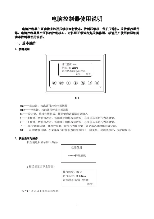
1、按键说明
图1
ON——起动键:按此键可起动电机运行
OFF——停机键:按此键可停止电机运行
M——设定键:修改完数据后,按此键确认数据存储输入
❽——上移键:数据修改时,按此键上翻修改该数位;在菜单选择时作为选择键。
❾——下移键:数据修改时,按此键下翻修改该数位;在菜单选择时作为选择键。
❼——移位键/确认键:修改数据时,此键作为移位键;在菜单选择时作为确定键。
RT——返回键/复位键:在菜单操作时作为返回键返回上一级菜单;故障停机时,按此键复位。
2、状态显示与操作
机组通电后显示如下界面:
5秒后显示以下主界面:
按“❾”进入以下菜单选择界面:
a、运行参数查看
按“❾”或“❽”移动黑色滚动条到“运行参数”菜单后,按确认键“❼”后弹出下一级菜单:
再按“❼”弹出
如为最后一级菜单,界面不会出现黑色滚动条,按返回键“RT”返回上级菜单或主界面。
如在某一界面停止操作,数秒钟后自动返回主界面。
用“❾”、“❽”移动键、确认键“❼”和返回键“RT”根据上述方法可完全观察到运行时间、本次运行时间、维护参数、历史故障、出厂日期、现场故障等运行参数并返回到上级菜单。
b、日历时间
按“❾”或“❽”移动黑色滚动条到“日历”菜单后,按确认键“❼”后弹出
在停机状态下可对日期、时间进行调整,操作方法为:
按“❾”或“❽”移动黑色滚动条到需修改的参数项后按确定键“❼”后出现闪烁位,此时“❾”和“❽”键变为上翻和下翻键修改当前位,“❼”变为移位键移动修改位。
修改完毕后按“M”确认并保存,“❾”或“❽”变回移动黑色滚动条,“❼”变回返回键。
c、用户参数
1)、参数修改方法
══在运行状态和停机延时过程中不能修改用户参数和厂家参数══
用前述运行参数查看的方法可查看和修改用户参数,如修改压力上限,操作方法如下:
按“❾”或“❽”移动黑色滚动条到“用户参数”项后按确定键“❼”弹出
再按确定键 “❼”弹出
如不继续按确定键 “❼”即可查看用户参数。
再按确定键 “❼”弹出如下界面要求输入用户密码:
注:用户密码在用户参数里可修改
此界面弹出后,出现闪烁位,此时“❾” 和“❽”键变为上翻和下翻键修改当前位, “❼”变为移位键移动修改位,最后按“M ”确认输入。
弹出界面:
右上角有“*”提示,表示已
进入用户参数设定状态。
“❾” 或“❽”变回移动黑色滚动条,“❼”变回确定键。
滚动条在“压力上限”处按确认
键“❼”,此时出现闪烁位,“❾” 和“❽”键变为上翻和下翻键修改当前位, “❼”变为移位键移动修改位,输入完毕按“M ”确认,闪烁位消失。
“❾” 或“❽”变回移动黑色滚动条,“❼”变回确定键可继续修改其它用户参数。
如不需修改其它参数,按“RT ”键返回上级菜单或主菜单。
用同样方法可修改其它用户参数。
2)用户参数及功能
二、功能及技术参数
1、开关量:9路开关量输入,10路继电器开关量输出;
2、模拟量:二路Pt100温度输入,二路4~20mA变送输入,两组三相电流输入(配套CT);
3、相序输入电压:三相380V;
4、控制器工作电源:220V、50Hz、20V A;
5、显示量程
a)、油温:—20~150℃;精度:±1℃。
b)、气温:—20~150℃;精度:±1℃。
c)、运行时间:0~999999小时。
d)、电流显示量程:0~999.9A。
e)、压力:0~1.60MPa。
精度;0.01Mpa。
6、相序保护:当保护器检测到错相时,动作时间≤2s;
7、电机保护:本控制器对主电机和风扇电机均具有以上五种基本保护功能
①、堵转保护:起动结束后,当工作电流达到设定电流的四至八倍时,动作时间≤0.2s;
②、短路保护:只要检测电流达到设定电流的八倍以上时,动作时间≤0.2s;
③、缺相保护:当任何一相电源缺相时,动作时间≤2s;
④、不平衡保护:任何两相间电流相差60~75%时,动作时间≤5s;
⑤、过载反时限保护特性(时间单位为秒),见下表。
倍数=I实/I设定
当电机运行电流大于或等于设定电流的1.2倍至3.0倍时按下表的过载倍数及动作时间延时动作
表2、电机保护反时限曲线表
8、温度保护:当检测到的实际温度大于设定温度时,动作时间≤2s;
9、输出继电器触点容量:250V5A;触点寿命500000次;
10、电流显示误差小于1.0%.;
11、RS—485通讯
三、预警与提示
(1)、文本显示器提示
①、空滤器预警指示
a、用开关信号检测预警
控制器通过检测空滤器压差开关动作在文本显示器上提示操作者“空滤器阻塞”。
b、设定空滤器使用时间预警
空滤器使用时间到,文本显示器上提示操作者“空滤器使用时间到”。
②、油滤器预警指示
a、用开关信号检测预警
控制器通过检测油滤器压差开关动作在文本显示器上提示操作者“空滤器阻塞”。
b、设定油滤器使用时间预警
空滤器使用时间到,文本显示器上提示操作者“油滤器使用时间到”。
③、油分器预警指示
a、用开关信号检测预警
b、设定油分器使用时间预警
空滤器使用时间到,文本显示器上提示操作者“油分器使用时间到”。
④、润滑油预警指示
润滑油使用时间到,文本显示器上提示操作者“润滑油使用时间到”
⑤、润滑脂预警指示
润滑脂使用时间到,文本显示器上提示操作者“润滑脂使用时间到”
(2)、主控器提示
四、安全保护
①、对电机的保护
MAM—KY02S空压机控制器对电机具有短路、堵转、过载、缺相、不平衡进行保护。
②、排气超温保护
排气温度高于设定温度高限控制器报警停机,现场故障显示“排气温高”。
③、空压机防逆转保护
当接入空压机的三相电源相序与控制器设置不一样时,现场故障显示“相序错误”,控制器不能起动电机。
此时仅需任意交换两相电源线并看电机转向即可。
④、供压超压保护
排气压力高于设定的压力高限时控制器报警停机,现场故障显示“排气压力高”。
⑤、传感器失灵保护
当压力传感器或温度传感器断线时,控制器报警停机。
现场故障显示“**传感器失灵”。
⑥、联动保护
主机运行,排气温度已到风机启动温度,但风机未运行控制器报警停机,现场故障显示“风机
五、常见故障的处理
由于控制器外部器件引起的故障停机可通过查询现场故障或历史故障查出故障原因,排除外围故障。
具体方法如下:
按“❾”或“❽”移动黑色滚动条到“运行参数”菜单后,按确认键“❼”后弹出下一级菜单:
一直按“❾”键弹出
按“❼”键如弹出如下故障原因:
此时主要检查温度传感器是否断线,传感器是否损坏等。
常见故障及原因:。