IMM User Guide
- 格式:doc
- 大小:1.30 MB
- 文档页数:9

Windows输入法编程接口Windows9x系统下汉字输入法的基本原理Windows系统下汉字输入法实际上是将输入的标准ascii字符串按照一定的编码规则转换为汉字或汉字串,进入到目的地。
由于应用程序各不相同,用户不可能自己去设计转换程序,因此,汉字输入自然而然落到WINDOWS系统管理中。
一、输入法与系统的关系键盘事件应用程序||Windows的USER.EXE|输入法管理器|输入法系统的键盘事件有windows的user.exe软件接收后,user.exe在将键盘事件传导输入法管理器(Input Method Manager,简称IMM)中,管理器再将键盘事件传到输入法中,输入法根据用户编码字典,翻译键盘事件为对应的汉字(或汉字串),然后再反传到user.exe中,user.exe再将翻译后的键盘事件传给当前正运行的应用程序,从而完成汉字的输入。
二、汉字输入法的组成微软Windows9x系统中汉字输入法的名称是"Input Method Editor" ,简称IME,输入法的程序名称为:*.ime,数据文件名称为*.MB,即通常说的输入法编码表(字典).实际上IME文件是一个动态连接库程序(DLL),它与dll文件没有区别,只是名称不同而已。
一般汉字输入法都由三个窗口组成:状态窗口(Status Windows)-显示当前的输入法状态(中文还是英文等站环信息);编码输入窗口(Composition Windows)-显示当前击键情况;汉字选择窗口(Candidates Windows)-列出当前编码的全部汉字(串),供用户选择或查询。
上述三个窗口由基本的用户接口(User Interface )函数管理着。
现在我们用Dumpbin.exe打开微软提供的拼音输入法(WINDOWS\SYSTEM\WINPY.IME)看看它有什么组成(这里一WINDOWS98为例,并假定windows系统安装在c:盘下):C:\Dumpbin c:\windows\system\winpy.imeMicrosoft (R) COFF Binary File Dumper Version 6.00.8168Copyright (C) Microsoft Corp 1992-1998. A ll rights reserved.Dump of file WINPY.IMEFile T ype: DLL //IME 实际为dll程序Section contains the following exports for WINPY.ime0 characteristics34A37323 time date stamp Fri Dec 26 17:04:35 19970.00 version1 ordinal base19 number of functions //共有19个函数19 number of names // 对应19个名称ordinal hint RVA name1 0 0000A010 CandWndProc //"选择汉字窗口"注册函数2 1 0000E750 CompWndProc //"输入编码窗口"注册函数3 2 0000FB50 ImeConfigure //配置当前ime参数函数4 3 0000FEC0 ImeConversionList//将字符或字符串转换成目标字符5 4 0000FFA0 ImeDestroy //退出当前使用的IME6 5 000030D0 ImeEnumRegisterWord7 6 0000FFB0 ImeEscape //应用软件访问输入法的接口函数.8 7 00003080 ImeGetRegisterWordStyle9 8 0000E9A0 ImeInquire //启动并初始化当前IME输入法10 9 0000A800 ImeProcessKey //IME输入键盘事件管理函数11 A 00002C20 ImeRegisterWord //向输入法字典注册字符串12 B 000109A0 ImeSelect //启动当前IME输入法13 C 000109E0 ImeSetActiveContext //设置当前的输入处于活动状态.14 D 0000C850 ImeSetCompositionString 由应用程序设置输入法编码15 E 0000AEE0 ImeT oAsciiEx //将输入的键盘事件转换为汉字编码事件16 F 00002F40 ImeUnregisterWord //删除被注册的字符串.17 10 0000CA90 NotifyIME //IME事件管理函数18 11 00005160 StatusWndProc //状态窗口注册函数19 12 00002350 UIWndProc //用户界面接口函数Summary5000 .ShareDa7000 .data2000 .idata1000 .rdata3000 .reloc5000 .rsrc2000 .sgroup18000 .text从上述可以看出,IME程序共有19个出口函数组成,每一个函数都有特定的格式,它们担负着与windows 系统传递信息的作用,这些函数是供Windows系统调用的。

联想服务器IMM运维管理指南Integrated Management Module II (IMM2) 基本操作(远程管理端口)目录一、登陆IMM远程管理界面 (3)1. 设置固定的IMM远程管理口IP地址登陆 (4)2. 临时登陆 (7)3. 在Windows操作系统中,通过带内接口登陆 (9)二、IMM管理界面简介 (11)三、IMM常用操作说明 (37)1. 查看、导出日志及熄灭日志检查指示灯 (37)2. 微码刷新 (43)3. 远程终端 (65)一、登陆IMM远程管理界面找到服务器背面的IMM远程管理口,一般会标记为”IMM”或者有一个扳手型的标志,参考《认识您的System X服务器》(知识库编号:154325)。
在System x3650 M5等主流型服务器上有单独的IMM远程管理口。
在System x3250 M5等低端型服务器上IMM远程管理口与普通网口复用。
IMM远程管理的默认登陆用户名及密码为:用户名:USERID密码:PASSW0RD(数字0)1. 设置固定的IMM远程管理口IP地址登陆开机看到Lenovo System x Logo时按F1键进入BIOS界面,进入System Settings。
再进入Integrated Management Module。
进入Network Configuration设置IMM远程管理口的IP地址。
注:如果IMM无法登陆或者发生问题需要恢复,可以选择”Reset IMM to Defaults”恢复IMM默认设置(包括IP地址及用户),或者选择”Reset IMM”重启IMM功能。
在BIOS中恢复或重启IMM可能会出现数分钟操作无响应的情况,风扇也会全速转动。
对于有独立IMM远程管理口的System x机型,X3650M5的第一项”Network Interface Port”为"Dedicated";对于共享网口的机型,该项为"Shared",一般不需要做改动。

Knee CrutchInstructions for UseProduct No. F-KCP80028231Version BENGLISH (3)中文简体 (18)DANSK (34)NEDERLANDS (49)SUOMI (65)FRANÇAIS (80)DEUTSCH (96)ΕΛΛΗΝΙΚΑ (113)ITALIANO (131)日本語版 (147)한국어 (162)NORSK (177)POLSKI (192)PORTUGUÊS (209)ROMÂNESC (225)РУССКИЙ (241)SRPSKI (259)SLOVENSKY (275)SLOVENŠČINA (291)ESPAÑOL (306)SVENSKA (322)TURK (338)IMPORTANT NOTICESPrior to using this or any other type of medical apparatus with apatient, it is recommended that you read the Instructions for Use andfamiliarize yourself with the product.•Read and understand all warnings in this manual and on the device itself prior to use with a patient.•The symbol is intended to alert the user to important procedures or safety instructions regarding the use of this device.The symbol on the labels is intended to show when the IFU should be referenced for use.•The techniques detailed in this manual are onl y manufacturer’s suggestions. The final responsibility for patient care with respect to thisdevice remains with the attending physician.•Device function should be checked prior to each usage.•This device should only be operated by trained personnel.•All modifications, upgrades, or repairs must be performed by an authorized specialist.•Keep this manual available for future reference.•Any serious incident that has occurred in relation to the device should be reported to the manufacturer and the competent authority listed in this document.Knee Crutch (F-KCP)1General Information (6)1.1Copyright Notice: (6)1.2Trademarks: (6)1.3Contact Details: (7)1.4Safety Considerations: (7)1.4.1Safety hazard symbol notice: (7)1.4.2Equipment misuse notice: (7)1.4.3Notice to users and/or patients: (7)1.4.4Safe disposal: (7)1.5Operating the system: (8)1.5.1Applicable Symbols: (8)1.5.2Intended User and Patient Population: (9)1.5.3Compliance with medical device regulations: (9)1.6EMC considerations: (9)1.7EC authorized representative: (9)1.8Manufacturing Information: (10)2System (10)2.1System components Identification: (10)2.2Product Code and Description: (10)2.3List of Accessories and Consumable Components Table: (11)2.4Indication for use: (11)2.5Intended use: (11)2.6Residual risk: (11)3Equipment Setup and Use: (12)3.1Prior to use: (12)3.2Setup: (12)3.3Device controls and indicators: (13)3.4Storage, Handling and Removal Instructions: (13)3.4.1Storage and Handling: (13)3.4.2Removal Instruction: (13)3.5Troubleshooting Guide: (13)3.6Device Maintenance: (13)4Safety Precautions and General Information: (14)4.1General Safety Warnings and Cautions: (14)4.2Product Specifications: (15)4.3Sterilization Instruction: (15)4.4Cleaning and Disinfection Instruction: (16)5List of Applicable Standards: (16)1General InformationAMATECH Corporation is a subsidiary of Allen Medical Systems, Inc. which is asubsidiary of Hill-Rom, Inc. (NYSE: HRC), a leading worldwide manufacturer and provider of medical technologies and related services for the health care industry.As an industry leader in patient positioning, our passion is improving patientoutcomes and caregiver safety, while enhancing our customers' efficiency. Our inspiration comes from providing innovative solutions to address our customers' most pressing needs. We immerse ourselves in our customers' world, to better address these needs and the daily challenges of their environment. Whether developing a solution to address patient positioning challenges or creating a system to offer safe and effective surgical site access for the surgical team, we are committed toproviding products of exceptional value and quality.1.1Copyright Notice:Revision© 2019 Allen Medical Systems Inc. ALL RIGHTS RESERVED.No part of this text shall be reproduced or transmitted in any form or by anymeans, electronic or mechanical, including photocopying, recording, or by any information or retrieval system without written permission from Allen MedicalSystems, Inc. (Allen Medical).The information in this manual is confidential and may not be disclosed to thirdparties without the prior written consent of Allen Medical.1.2Trademarks:Trademark information can be found in /pages/terms-conditions.Product may be covered by one or more patents. Please consult listing at/patents for any patent(s).1.3Contact Details:For complains or ordering information, please contact your supplier and refer to the catalog. All modifications, upgrades, or repairs must be performed by an authorized specialist.1.4Safety Considerations:1.4.1Safety hazard symbol notice:DO NOT USE IF PRODUCT SHOWS VISIBLE DAMAGE AND MATERIALDEGRADATION.1.4.2Equipment misuse notice:Do not use product if package is damaged or unintentionally opened before use.All modifications, upgrades, or repairs must be performed by an authorized specialist.1.4.3Notice to users and/or patients:Any serious incident that has occurred in relation to the device should be reported using the contact details provided in section 1.3 of this Instruction for Use and to the competent authority of the Member State in which the user and/or patient is established.Note: Refer to the surgical table manufacturer's user guide for instructions on use.Always refer to the surgical table manufacturer’s weight limits.NEVER EXCEED THE WEIGHT CAPACITY OF THE OPERATING ROOM TABLE1.4.4Safe disposal:Customers should adhere to all federal, state, regional, and/or local laws and regulations as it pertains to the safe disposal of medical devices and accessories.If in doubt, the users of the device shall first contact their supplier for guidance on safe disposal protocols.1.5Operating the system:1.5.1Applicable Symbols:Symbol used Description ReferenceIndicates the device is a medical device MDR 2017/745Indicates the medical device manufacturer EN ISO 15223-1Indicates the manufacturer’s serial number.The device serial number is encoded as1YYWWSSSSSSS.∙YY indicates the year of manufacture. i.e.118WWSSSSSSS where 18 represents theyear 2018.∙WW indicates the number of themanufacturing week per a standard shopcalendar. (Leading zeros included.)∙SSSSSSS is a sequential unique number.EN ISO 15223-1Indicates the medical device Global Trade Item Number 21 CFR 830 MDR 2017/745Indicates the date when the medical devicewas manufacturedEN ISO 15223-1Indicates the manufacturer’s lot code usingthe Julian Date yyddd, where yy indicates thelast two digits of the year and ddd indicatesthe day of the year. i.e. April 4th, 2019 would berepresented as 19094.EN ISO 15223-1Indicates the manufacturer’s cataloguenumberEN ISO 15223-1Indicates the need for the user to consult theinstructions for use for important cautionaryinformation such as warnings and precautionsEN ISO 15223-1Indicates the device do not contain naturalrubber or dry natural rubber latexEN ISO 15223-1Indicates the authorized representative in theEN ISO 15223-1European CommunityIndicates the Medical Device complies toMDR 2017/745REGULATION (EU) 2017/745Indicates a Warning IEC 60601-1Intended to show when the IFU should bereferenced for use EN ISO 15223-11.5.2Intended User and Patient Population:Intended User: Surgeons, Nurses, Doctors, Physicians and OR healthcareprofessionals involved in the device intended procedure. Not intended for Laypersons.Intended Populations:This device is intended to be used with patients that do not exceed the weight in the safe working load field specified in the product specification section 4.21.5.3Compliance with medical device regulations:This product is a non-invasive, Class I Medical Device. This system is CE-marked according to Annex VIII, Rule 1, of the Medical DeviceRegulations (REGULATION (EU) 2017/745)1.6EMC considerations:This is not an electromechanical device. Therefore, EMC Declarations are not applicable.1.7EC authorized representative:HILL-ROM SASB.P. 14 - Z.I. DU TALHOUET56330 PLUVIGNERFRANCETEL: +33 (0)2 97 50 92 121.8 Manufacturing Information:ALLEN MEDICAL SYSTEMS, INC. 100 DISCOVERY WAY ACTON, MA 01720 USA800-433-5774 (NORTH AMERICA) 978-266-4200 (INTERNATIONAL)2 System2.1 System components Identification:2.2 Product Code and Description:F-KCP - Knee Crutch, PairBootPadHandleClamp2.3List of Accessories and Consumable Components Table:The following list are accessories and components that may be used with thisdevice.Note: Consult the corresponding IFU for the products mentioned in the above table.2.4Indication for use:The Knee Crutch is used in a variety of short surgical procedures including, but not limited to cystoscopy surgery. These devices are capable of being used with a broad patient population as determined appropriate by the caregiver or institution.2.5Intended use:The Knee Crutch is designed to position and support the patient’s lower leg and upper leg in a variety of short surgical procedures including, but not limited to cystoscopy surgery. These devices are intended to be used by healthcare professionals within the Operating Room setting.2.6Residual risk:This product complies with relevant performance, safety standards. However, user or patient harm from misuse, device damage, function or mechanical hazards cannot be completely excluded.3Equipment Setup and Use:3.1Prior to use:a.Inspect the product looking for any visible damage or sharp edges that couldbe caused by a drop or impact during storage.b.Make sure product has been properly cleaned and disinfected and wiped dryprior to each use.3.2Setup:a.Place patient on table in a comfortable position.b.Mount the Knee Crutch into an adjustable clamp located adjacent to thepatient’s hip joint.c.Place Knee Crutch into the desired amount of abduction, then lock clampssecurely.d.Once the Knee Crutches are located to the desired position of the patient’scalves and height is set approximately, tighten Lock Handle on the KneeCrutch.e.Ensure that the Knee Crutch pads are in place and arranged properly. TheKnee Crutch straps should be out of the way.f.If the patient is anesthetized, obtain adequate help to place both legs intothe Knee Crutches simultaneously; this significantly reduces risk of patientinjury.g.Adjust the Knee Crutch position by placing a supporting hand near the mountunderneath the Knee Crutch. Loosen the Knee Crutch Lock Handle, and railclamp. Adjust crutch height, rotation, lithotomy angle, andabduction/adduction. Align the knee, hip and opposing shoulder. Retightenthe Knee Crutch Lock Handle, and rail clamp.h.Ensure that all clamps are securely locked.i.Secure the Knee Crutch straps. Avoid tightening these straps against the leg.You should be able to slip your finger between the leg and strap at thetightest point. If it is necessary to restrain the leg more securely, adequatepadding should be applied between the straps and the leg.j.Check to ensure that no undue pressure is being applied to the leg. Do not permi t anyone or anything to lean on the patient’s leg at any time.3.3Device controls and indicators:The indicators below are placed on the sole of each boot.This Symbol represent the patient‘s right foot.This Symbol Represent the Patient’s left foot.3.4Storage, Handling and Removal Instructions:3.4.1Storage and Handling:The product should be stored in a clean and safe environment to prevent product damage. See storage Specifications under Product Specification section.3.4.2Removal Instruction:a.Remove the Clamp handle from the O.R. table rail.b.Remove the Knee crutches from the Tri Clamp.c.Remove the Tri Clamp from the side rail.3.5Troubleshooting Guide:This device does not have a troubleshooting guide. For technical support user of the device shall first contact his or her supplier.3.6Device Maintenance:Make sure that all labels are installed and can be read. Replace labels asnecessary by using a plastic scraper to remove the label. Use an alcohol wipe to remove any adhesive residue.Contact us if you need to repair or replace the device by using the information from the contact details section (1.3).4Safety Precautions and General Information:4.1General Safety Warnings and Cautions:WARNING:a.Do not use if product shows visible damage.b.Prior to using this device, please read the instructions for equipment set up anduse. Familiarize yourself with the product before application on a patient.c.To prevent patient and/or user injury and/or equipment damage, examine thedevice and surgical-table side rails for potential damage or wear prior to use. Do not use the device if damage is visible, if parts are missing or if it does not function as expected.d.To prevent patient and/or user injury and/or equipment damage, verify thedevice attaching clamps completely touch the table-side rails and are firmly in place. Test the locking mechanism to ensure no movement when elevated or pushed.e.The patient's toes may extend beyond the end of the stirrup boot.f.The product must be used with compatible clamps.g.Check for patient contact pressure points and consult the physician before use.h.Only use approved pad.i.Ensure the patient's legs are secure in the boot prior to adjusting.CAUTION:a.Do not raise thigh closer to torso than 90º as patient may experience nervedamage.b.To prevent patient and/or user injury and/or equipment damage: allmodifications, upgrades, or repairs must be performed by an Allen authorizedspecialist. Failure to comply may void warranty.c.Do not exceed safe working load shown in the product specification table.4.2Product Specifications:Note: Consult the corresponding IFU for the products mentioned in the above table.4.3Sterilization Instruction:This device is not intended to be sterilized. Equipment damage may occur.4.4Cleaning and Disinfection Instruction:WARNING:∙Do not use bleach or products that contain bleach to clean the device. Injury or equipment damage can occur.∙After each use, clean the device with alcohol-based wipes.∙Do not put the device into water. Equipment damage can occur.∙Use a cloth and a quaternary ammonium disinfecting/cleaning solution to clean and disinfect the device.∙Read and follow the manufacturer’s recommendation for low-level disinfection.∙Read and follow the cleaning product’s instructions. Use caution in areas where liquid can get into the mechanism.∙Wipe the device with a clean, dry cloth.∙Make sure that the device is dry before you store it or use it again.CAUTION: DO NOT IMMERSE PADS IN ANY LIQUIDCAUTION: DO NOT USE BLEACH OR PHENOLICS ON PADS5List of Applicable Standards:Sl. no Standards Description1.EN 62366-1Medical devices - Part 1: Application of usability engineering to medical devices2.EN ISO 14971 Medical devices- Application of risk management to medical devices.3.EN 1041 Information supplied by the manufacturer of medical devices4.EN ISO 15223-1 Medical devices - Symbols to be used with medical device labels, labelling and information to be supplied - Part 1: General requirements5.EN ISO 10993-1 Biological evaluation of medical devices - Part 1: Evaluation and testing within a risk management process6.IEC 60601-2-46 Medical electrical equipment - Part 2-46: Particular requirements for the basic safety and essential performance of operating tables7.ISTA International Safe Transit Association standards for package testingKnee Crutch使用说明产品编号 F-KCP80028231Version B重要声明将本设备或其他类型的医疗仪器用于患者之前,建议您先阅读本《使用说明》并熟悉该产品。

Windows输入法编程接口Windows9x系统下汉字输入法的基本原理Windows系统下汉字输入法实际上是将输入的标准ascii字符串按照一定的编码规则转换为汉字或汉字串,进入到目的地。
由于应用程序各不相同,用户不可能自己去设计转换程序,因此,汉字输入自然而然落到WINDOWS系统管理中。
一、输入法与系统的关系键盘事件应用程序||Windows的USER.EXE|输入法管理器|输入法系统的键盘事件有windows的user.exe软件接收后,user.exe在将键盘事件传导输入法管理器(Input Method Manager,简称IMM)中,管理器再将键盘事件传到输入法中,输入法根据用户编码字典,翻译键盘事件为对应的汉字(或汉字串),然后再反传到user.exe中,user.exe再将翻译后的键盘事件传给当前正运行的应用程序,从而完成汉字的输入。
二、汉字输入法的组成微软Windows9x系统中汉字输入法的名称是"Input Method Editor" ,简称IME,输入法的程序名称为:*.ime,数据文件名称为*.MB,即通常说的输入法编码表(字典).实际上IME文件是一个动态连接库程序(DLL),它与dll文件没有区别,只是名称不同而已。
一般汉字输入法都由三个窗口组成:状态窗口(Status Windows)-显示当前的输入法状态(中文还是英文等站环信息);编码输入窗口(Composition Windows)-显示当前击键情况;汉字选择窗口(Candidates Windows)-列出当前编码的全部汉字(串),供用户选择或查询。
上述三个窗口由基本的用户接口(User Interface )函数管理着。
现在我们用Dumpbin.exe打开微软提供的拼音输入法(WINDOWS\SYSTEM\WINPY.IME)看看它有什么组成(这里一WINDOWS98为例,并假定windows系统安装在c:盘下):C:\Dumpbin c:\windows\system\winpy.imeMicrosoft (R) COFF Binary File Dumper Version 6.00.8168Copyright (C) Microsoft Corp 1992-1998. All rights reserved.Dump of file WINPY.IMEFile Type: DLL //IME 实际为dll程序Section contains the following exports for WINPY.ime0 characteristics34A37323 time date stamp Fri Dec 26 17:04:35 19970.00 version1 ordinal base19 number of functions //共有19个函数19 number of names // 对应19个名称ordinal hint RVA name1 0 0000A010 CandWndProc //"选择汉字窗口"注册函数2 1 0000E750 CompWndProc //"输入编码窗口"注册函数3 2 0000FB50 ImeConfigure //配置当前ime参数函数4 3 0000FEC0 ImeConversionList//将字符或字符串转换成目标字符5 4 0000FFA0 ImeDestroy //退出当前使用的IME6 5 000030D0 ImeEnumRegisterWord7 6 0000FFB0 ImeEscape //应用软件访问输入法的接口函数.8 7 00003080 ImeGetRegisterWordStyle9 8 0000E9A0 ImeInquire //启动并初始化当前IME输入法10 9 0000A800 ImeProcessKey //IME输入键盘事件管理函数11 A 00002C20 ImeRegisterWord //向输入法字典注册字符串12 B 000109A0 ImeSelect //启动当前IME输入法13 C 000109E0 ImeSetActiveContext //设置当前的输入处于活动状态.14 D 0000C850 ImeSetCompositionString 由应用程序设置输入法编码15 E 0000AEE0 ImeT oAsciiEx //将输入的键盘事件转换为汉字编码事件16 F 00002F40 ImeUnregisterWord //删除被注册的字符串.17 10 0000CA90 NotifyIME //IME事件管理函数18 11 00005160 StatusWndProc //状态窗口注册函数19 12 00002350 UIWndProc //用户界面接口函数Summary5000 .ShareDa7000 .data2000 .idata1000 .rdata3000 .reloc5000 .rsrc2000 .sgroup18000 .text从上述可以看出,IME程序共有19个出口函数组成,每一个函数都有特定的格式,它们担负着与windows 系统传递信息的作用,这些函数是供Windows系统调用的。

IMM使用指南一.如何访问IMM (1)二.IMM主要功能介绍 (4)三.几个常用功能 (5)1.远程开关机 (5)2.通过IMM刷新服务器的UEFI/IMM微码 (6)3.远程终端功能 (7)一.如何访问IMM通常主机后部有一个专用的管理端口,例如下图以3650M3为例,可以通过此端口访问IMM。
IMM管理端口默认IP:192.168.70.125用户名:USERID密码:PASSW0RD注意字母为大写,密码中的“0”是数字0在UEFI中修改IMM的IP地址在开机自检的过程中根据提示按F1进入UEFI设置,在UEFI中进入System Setting->Integrated Management Module->Network configuration。
在输入需要修改的IP地址后,选择Save Network Settings在IE中输入IP地址即可访问IMM管理界面二.IMM主要功能介绍System status查看服务器的健康状况,包括温度、电压和风扇状态等。
Virtual Light Path查看服务器光通路诊断板上是否有告警。
Event Log可以查看服务器的日志信息,可以用Save Log as Text File另存日志信息为文本文件。
Vital Product Data查看服务器的型号序列号及各种微码版本。
Power/Restart通过IMM控制开关服务器,包括定时开关机功能Remote Control远程控制服务器终端,需要添加IBM Virtual Media Key选件来实现此功能,大部分机型标配没有此选件。
PXE Network Boot设置服务器的PXE启动。
Firmware Update刷新服务器的UEFI和IMM的微码。
System Settings设置IMM的时间日期,名字等基本信息。
Login Profiles为IMM添加除默认之外的其他用户。
Alerts设置snmp告警等信息。
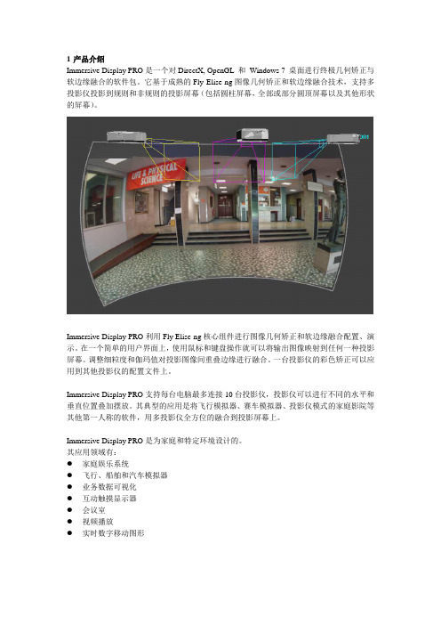
Immersive Display PRO是一个对DirectX, OpenGL 和Windows 7 桌面进行终极几何矫正与软边缘融合的软件包。
它基于成熟的Fly Elise-ng图像几何矫正和软边缘融合技术,支持多投影仪投影到规则和非规则的投影屏幕(包括圆柱屏幕,全部或部分圆顶屏幕以及其他形状的屏幕)。
Immersive Display PRO利用Fly Elise-ng核心组件进行图像几何矫正和软边缘融合配置、演示。
在一个简单的用户界面上,使用鼠标和键盘操作就可以将输出图像映射到任何一种投影屏幕。
调整细粒度和伽玛值对投影图像间重叠边缘进行融合。
一台投影仪的彩色矫正可以应用到其他投影仪的配置文件上。
Immersive Display PRO支持每台电脑最多连接10台投影仪,投影仪可以进行不同的水平和垂直位置叠加摆放。
其典型的应用是将飞行模拟器、赛车模拟器、投影仪模式的家庭影院等其他第一人称的软件,用多投影仪全方位的融合到投影屏幕上。
Immersive Display PRO是为家庭和特定环境设计的。
其应用领域有:●家庭娱乐系统●飞行、船舶和汽车模拟器●业务数据可视化●互动触摸显示器●会议室●视频播放●实时数字移动图形以下是所需的最低配置:2.1 2.0GHz或更高处理器(32位或64位)2.22G或以上内存2.3一个合适的显卡(NVIDIA 或AMD/ATI)2.4为能够在Windows7下进行广泛的多投影仪显示,需做以下要求:2.4.1NVIDIA显卡需要支持NVIDIA环绕2D2.4.2ATI 显卡需要支持ATI Eyefinity(宽域多屏显卡)2.4.3Matrox DialHead2GO或者TrippleHead2GO(多屏宝),外部硬件盒2.5需要Administrator权限安装Immersive Display PRO2.6不需要Administrator权限运行Immersive Display PRO3安装和卸载3.1安装注意:Immersive Display PRO使用DirectX运行时集约。
用户手册ADI-8 DS Mk III真正的工业标准高精度24 Bit / 192 kHz参考级别低延迟转换8通道模拟<> AES / ADAT 接口24 Bit / 192 kHz 数字音频ADAT <> AES 格式转换器24 Bit 接口重要的安全说明 (4)概述 (5)1. 介绍 (6)2. 包装清单 (6)3. 简介及主要特点 (6)4. 首次使用——快速上手 (7)4.1 控制、接口与显示 (7)4.2 快速上手 (8)5. 附件 (9)6. 产品保证 (10)7. 附录 (10)CE / FCC符合性声明 (11)使用和操作 (12)8. 前面板操作 (13)8.1 Select(选择)键 (13)8.2 A/D State(A/D状态)- Meters(电平表) (13)8.3 A/D Output(A/D输出) (13)8.4 Patch Mode(批处理模式) (13)8.5 Clock(时钟) (14)8.6 D/A Input(D/A输入) (15)8.7 D/A State(D/A状态)- Meters(电平表) (15)8.8 D/A Reference(D/A参考) (15)输入和输出 (16)9. 模拟输入/输出 (17)9.1 Line In(线路输入) (17)9.2 Line Out(线路输出) (18)10. 数字输入/输出 (19)10.1 AES/EBU (19)10.2 ADAT光纤 (20)11.字时钟 (21)11.1字时钟输入和输出 (21)11.2 技术描述和使用 (22)11.3 布线和终止 (23)技术参考资料 (24)12. 技术指标 (25)12.1 模拟 (25)12.2 数字输入 (26)12.3 数字输出 (27)12.4 数字 (27)12.5 D-Sub AES/EBU接口针脚 (28)13. 技术背景 (30)13.1 技术 (30)13.2 锁定(Lock)与SyncCheck(同步检查) (31)13.3 延时(Latency)与监听(Monitoring) (32)13.4 DS –双倍速 (33)13.5 QS –四倍速 (33)13.6 AES/EBU - SPDIF (34)13.7 DS/QS模式下的噪声电平 (35)13.8 SteadyClock(稳定时钟) (36)14. 框图 (37)重要的安全说明注意! 不要打开底盘,以防触电。
Nonlinear Structural Materials ModuleUser’s GuideC o n t a c t I n f o r m a t i o nVisit the Contact COMSOL page at /contact to submit general inquiries or search for an address and phone number. You can also visit the Worldwide Sales Offices page at /contact/offices for address and contact information.If you need to contact Support, an online request form is located on the COMSOL Access page at /support/case . Other useful links include:•Support Center: /support•Product Download: /product-download•Product Updates: /support/updates•COMSOL Blog: /blogs•Discussion Forum: /forum•Events: /events•COMSOL Video Gallery: /videos•Support Knowledge Base: /support/knowledgebase Part number: CM022901N o n l i n e a r S t r u c t u r a l M a t e r i a l s M o d u l e U s e r ’s G u i d e © 1998–2022 COMSOLProtected by patents listed on /patents , or see Help>About COMSOL Multiphysics on the File menu in the COMSOL Desktop for a less detailed lists of U.S. Patents that may apply. Patents pending.This Documentation and the Programs described herein are furnished under the COMSOL Software License Agreement (/sla ) and may be used or copied only under the terms of the license agreement.COMSOL, the COMSOL logo, COMSOL Multiphysics, COMSOL Desktop, COMSOL Compiler, COMSOL Server, and LiveLink are either registered trademarks or trademarks of COMSOL AB. All other trademarks are the property of their respective owners, and COMSOL AB and its subsidiaries and products are not affiliated with, endorsed by, sponsored by, or supported by those trademark owners. For a list of such trademark owners, see /trademarks .Version: COMSOL 6.1The Nonlinear Structural Materials ModuleThe Nonlinear Structural Materials Module is an optional add-on package forCOMSOL Multiphysics® designed to assist you to model structural behavior thatincludes nonlinear materials. The module is an add-on to the Structural MechanicsModule or the MEMS Module and extends it with support for modeling nonlinearmaterials, including hyperelasticity, creep, plasticity, and viscoplasticity. The module isdesigned for researchers, engineers, developers, teachers, and students who want tosimulate nonlinear structural materials, including a full range of possible multiphysicscouplings.The module provides an extensive set of nonlinear structural material models,including:•Predefined and user-defined hyperelastic materials: neo-Hookean, Mooney–Rivlin,St.Venant–Kirchhoff, Arruda–Boyce, Ogden, and others.•Small-strain and large-strain plasticity models using different types of hardening.•User-defined plasticity, flow rule, and hardening models.•Porous plasticity models, used for example for powder compaction simulation.•Predefined and user-defined nonlinear elastic materials: Ramberg–Osgood, Powerlaw, and others.•Shape memory alloys.•Predefined and user-defined creep material models: Norton, Garofalo, Anand,potential, volumetric, deviatoric, and others.•Viscoplastic models: Anand, Chaboche, and Perzyna.•Models for damage in brittle materials.A C C E S S I N G T H E N O N L I N E A R S T R U C T U R A L M A T E R I A L S D O C U M E N T A T I O NThis is an add-on module requiring either the Structural Mechanics Module or theMEMS Module. The feature information, including theory and modeling details, isincluded in the Structural Mechanics Module User’s Guide.When you install COMSOL Multiphysics, the documentation sets are installed inseveral locations, both on your computer and most easily accessible while you areworking in COMSOL Multiphysics. The next section details where to access it.T H E N O N L I N E A R S T R U C T U R A L M A T E R I A L S M O D U L E|34 | T H E N O N L I N E A R S T R U C T U R A L M A T E R I A L S M O D U L EA C C E S S I N G C O M S O L D O C U M E N T A T I O N A N D A P P L I C A T I O N L IB R A R I E SA number of online resources have more information about COMSOL, including licensing and technical information. The electronic documentation, topic-based (or context-based) help, and the Application Libraries are all accessed through the COMSOL Desktop.T H E D O C U M E N T A T I O N A N D O N L I N E H E L PThe COMSOL Multiphysics Reference Manual describes the core physics interfaces and functionality included with the COMSOL Multiphysics license. This book also has instructions on how to use COMSOL Multiphysics and how to access the electronic Documentation and Help content.Opening Topic-Based HelpThe Help window is useful as it is connected to the features in the COMSOL Desktop. To learn more about a node in the Model Builder, or a window on the Desktop, click to highlight a node or window, then press F1 to open the Help window, which thendisplays information about that feature (or click a node in the Model Builder followedby the Help button (). This is called topic-based (or context) help .If you are reading the documentation as a PDF file on your computer,the blue links do not work to open an application or contentreferenced in a different guide. However, if you are using the Helpsystem in COMSOL Multiphysics, these links work to open othermodules, application examples, and documentation sets.().In the upper-right corner of the COMSOL Desktop, click the ()T H E N O N L I N E A R S T R U C T U R A L M A T E R I A L S M O D U L E | 5Opening the Documentation WindowT H E A P P L I C A T I O N L I B R A R I E S W I N D O W Each model or application includes documentation with the theoretical background and step-by-step instructions to create a model or application. The models andapplications are available in COMSOL Multiphysics as MPH-files that you can open for further investigation. You can use the step-by-step instructions and the actual models as templates for your own modeling. In most models, SI units are used to describe the relevant properties, parameters, and dimensions, but other unit systems are available.Once the Application Libraries window is opened, you can search by name or browse under a module folder name. Click to view a summary of the model or application and its properties, including options to open it or its associated PDF document. () button.Help>Help .(). () button.Help>Documentation.The Application Libraries Window in the COMSOL MultiphysicsReference Manual .6 | T H E N O N L I N E A R S T R U C T U R A L M A T E R I A L S M O D U L E Opening the Application Libraries WindowTo open the Application Libraries window ():C O N T A C T I N G C O M S O L B Y E M A I LForgeneralproductinformation,******************************.C O M S O L A C C E S S A ND TE C H N I C A L S U P P O R TTo receive technical support from COMSOL for the COMSOL products, please contact your local COMSOL representative or send your questions to******************.Anautomaticnotificationandacasenumberwillbesenttoyou by email. You can also access technical support, software updates, license information, and other resources by registering for a COMSOL Access account.menu, select () select ()C O M S O L O N L I N E R E S O U R C E SCOMSOL website Contact COMSOL /contactCOMSOL Access /accessSupport Center /supportProduct Download /product-downloadProduct Updates /support/updatesCOMSOL Blog /blogsDiscussion Forum /forumEvents /eventsCOMSOL Application Gallery /modelsCOMSOL Video Gallery /videoSupport Knowledge Base /support/knowledgebaseT H E N O N L I N E A R S T R U C T U R A L M A T E R I A L S M O D U L E|78|T H E N O N L I N E A R S T R U C T U R A L M A T E R I A L S M O D U L E。
User GuideTemperature and Humidity Datalogger Model 42280IntroductionCongratulations on your purchase of the Extech 42280 Thermometer and Relative Humidity Datalogger. The 42280 is a wall-mount, tripod mount, or desktop indoor air quality monitor with an internal memory capable of storing 16,000 readings (8000 temperature readings and 8000 relative humidity readings) that can later be transferred to PC using the USB interface. Real-time meter-to-PC logging is also supported. This meter is shipped fully tested and calibrated and, with proper use, will provide years of reliable service.Material listSupplied MaterialsMeterUser GuideUSB cableProgram CDFour (4) batteries; 1.5V ‘AA’9V adaptorOptional accessoriesCalibration bottles (33% and 75%) for Relative Humidity CalibrationFeaturesLarge LCD display shows temperature, humidity, and date/time clock simultaneously16,000 internal memory capacity (8000 temperature; 8000 RH%)Visual and Audible (with 117V AC adaptor only) AlarmsEasily configure datalogger through the keypad or via PC interfaceUSB PC interface with Windows TM softwareWall mount, tripod mount, or for desktop useMeter Description1. Humidity Sensor (internal Temperature sensor)2. Audible alarm (with AC adaptor power only)3. Visual Alarm LED4. Relative Humidity display5.Date and Time display6. Temperature display7. RECORD status LED8. USB port9.AC Adaptor jack10. Datalogger START-STOP button 11. MODE button 12. SET button 13. Up Arrow button 14. Down Arrow button 15. Tripod mount jackNotes: The battery compartment is located on rear of instrument. Desktop stand footers are notshown in diagram.LCD Display Description 1. Temperature Display 2.Dew Point icon3. Datalogger icon4. Date and Time5. Humidity Display6. Low battery icon245Important Note before startingThis meter relies on firm button presses to operate correctly. Be sure to press firmly and hold the button for as long as directed in the instructions.Meter Power1. The meter is powered by four (4) ‘AA’ 1.5V batteries or the 117V AC adaptor.2. When the batteries are installed or the adaptor is connected to an AC power source,momentarily press the START-STOP button to turn the meter ON.3. Press the START-STOP button again to turn the meter OFF.Viewing the displayed readings1. Normally, the top line indicates temperature in degrees C or F. Use the MODE button to switchbetween degrees C and degrees F.2. Press and hold the MODE for at least 2 seconds. This will change the top display to Dew Pointtemperature. The ‘DP’ icon will appear on the LCD when in Dew Point mode. Press and hold the MODE button for at least 2 seconds to return the top display to the normal temperature display mode.3. The middle line displays Relative Humidity in %.4. The bottom line automatically alternates between Time and Date displays.5. If the ALM status LED illuminates and the display flashes, one of the Alarm limits has beenreached. Program the High and Low Temperature/Humidity limits in Programming parameter P5 (detailed later in this user guide).Datalogger BasicsThe Model 42280 has a built-in Datalogger that can store up to 8000 temperature and 8000humidity readings. Readings can be stored in the meter and transferred at a later time to a PC. The meter can also display real-time readings on a connected PC; in other words, the PC can display readings at the instant the readings are taken.The meter must be configured before datalogging can be attempted. Parameters such as Real Time Clock and Datalogger Sample Rate must be programmed before datalogging can begin. It isstrongly recommended that the user take advantage of the supplied software to configure the meter.Instructions for manually configuring the meter are provided below; however configuring the meter via software is very convenient.Basic instructions for connecting the meter to a PC and getting started with the supplied software are provided later in this guide. Detailed instructions regarding the supplied software are provided ina separate manual included on the supplied CD-ROM and the HELP utility in the software program.Manual ProgrammingThe Model 42280 has several programming modes (P1, P2, P3, P4, P5, and P6). Theseparameters must be programmed before the Datalogger or the Alarm can be used.List of Programming ModesP1 - Number of samples to record (1, 2, 4, 8, 12, or 16 x 1000; 1=1000, 2=2000, etc.)P2 - Datalogging Start Methods (Immediate, Keypad, Scheduled, and Repeat modes)P3 – Start Time (set the time and date when Datalogging will automatically begin); Note that P3 will not appear in the menu if ‘SCh’ is not selected in P2.P4 - Sample Rate (set the datalogging interval from 1 second up to 12 hours)P5 - Alarm Mode (set High and Low Temperature/Humidity limits)P6 - Real Time Clock (set the meter’s internal date and time clock)Programming Mode P1; Number of readings (sample points) to record1. Press the SET button to access the setup mode2. Use the arrow buttons to select parameter P1 (see sample display below)3. Press the SET button again4. Use the up/down arrow buttons to select thedesired number of samples (in thousands) to recordfor a datalogging session (1, 2, 4, 8, 12, or 16;where 1=1000, 2=2000, 4=4000, and so on)5. Press the SET button to save setting6. Use the arrow buttons to select another programming mode or press MODE to exit theprogramming mode.Programming Mode P2; Datalogger Start Modes1. Press the SET button to access the setup mode2. Use the arrow buttons to select parameter P23. Press the SET button again4. Select one of the four Start modes using the up/down arrow buttons (see list and diagrambelow)a. rEp (Repeat Start mode): Logger startsonce readings are downloaded to PCb. hEy (Keypad Start): Datalogging beginsafter the START/STOP button is held for2 secondsc. imm (Immediate Start): Recording startsimmediately after exiting the setup moded. SCh (Scheduled Start): Logging beginsat a preset date and time5. Press the SET button to save the setting6. Use the arrow buttons to select anotherprogramming mode or press MODE to exit theprogramming mode.Programming Mode P3; Datalog Start Timeset to ‘SCh’).1. Press the SET button to access the setupmode2. Use the arrow buttons to select parameter P33. Press the SET button again4. Use the up/down arrow buttons to set the year5. Press the SET button again6. Use the up/down arrow buttons to set month7. Press the SET button again8. Use the up/down arrow buttons to set the day9. Press the SET button again10. Use up/down buttons to set the hours11. Press the SET button again12. Use up/down buttons to set the minutes13. Press the SET button again14. Use the up/down arrow buttons to set theseconds15. Press the SET button again to store the settings16. Press the MODE button to back out to the top level of this menu.17. Use the arrow buttons to select another programming mode or press MODE to exit theprogramming mode.Programming Mode P4; Datalogger Sample Rate1. Press the SET button to access the setup mode2. Use the arrow buttons to select parameter P43. Press the SET button again4. Use the up/down arrow buttons to set hours5. Press the SET button again6. Use the up/down arrow buttons to set the minutes7. Press the SET button again8. Use the up/down arrow buttons to set the seconds 9. Press SET again to store the settings10. Press the MODE button to back out to the top level of this menu.11. Use the arrow buttons to select another programming mode or press MODE to exit theprogramming mode. Programming Mode P5; High and Low Alarms1. Press the SET button to access thesetup mode 2. Use the arrow buttons to selectparameter P5 3. Press the SET button again4. Use the up/down arrow buttons to set theHigh Temperature Alarm limit 5. Press the SET button again6. Use the up/down arrow buttons to set theLow Temperature Alarm limit 7. Press the SET button again8. Use the up/down arrow buttons to set the High Humidity Limit 9. Press the SET button again10. Use the up/down arrow buttons to set the Low Humidity Limit 11. Press the SET button again to store the settings12. Press the MODE button to back out to the top level of this menu.13. Use the arrow buttons to select another programming mode or press MODE to exit theprogramming mode. Note:The AC Adaptor must be used for the audible alarm to soundProgramming Mode P6; Real Time Clock1. Press the SET button to access the setup mode2. Use the arrow buttons to select parameter P63. Press the SET button again4. Use the up/down arrow buttons to set the year5. Press the SET button again6. Use the up/down arrow buttons to set month7. Press the SET button again8. Use the up/down arrow buttons to set the day9. Press the SET button again10. Use the up/down arrow buttons to set the hours11. Press the SET button again12. Use the up/down arrow buttons to set the minutes13. Press the SET button again14. Use the up/down arrow buttons to set the seconds15. Press SET again to stores the settings16. Press the MODE button to back out to the top level of this menu.17. Use the arrow buttons to select another programming mode or press MODE to exit theprogramming mode.DataloggingStarting a Datalogging sessionThe 42280 can automatically store up to 16,000 readings (8000 temperature and 8000 humidity) for later transfer to PC. Program the controller, as discussed earlier, before Datalogging. If theDatalogger has not been configured at this point, configure as necessary. If programming iscomplete, continue with the next section.Starting the Datalogger by push-button (Key Mode)1. Programming mode P2 (Datalogging Start Modes) must be set to KEY (hEy) mode for thismethod.2. When P2 is set to ‘hEy’, press and hold the START-STOP button for 2 seconds.3. The REC front-panel status light will blink indicating that readings are currently recording atthe rate programmed in parameter P4 (sample rate)4. To stop recording, press and hold the START-STOP button for at least 2 seconds. The RECstatus light will stop blinking.Starting the Datalogger in Immediate Mode1. Programming mode P2 (Datalogging Start Modes) must be set to ‘Imm’ mode for this method.2. When the programming mode is exited, Datalogger automatically begins.3. The REC front-panel status light will blink indicating that readings are currently recording.4. To stop recording, press and hold the START-STOP button for at least 2 seconds. The RECstatus light will stop blinking.Starting the Datalogger in Schedule Mode1. In Schedule Mode the meter begins recording at a specific date and time, as programmed bythe user.2. Programming mode P2 (Datalogging Start Modes) must be set to ‘SCh’ mode for this method.3. After setting P2 to ‘SCh’, set the desired time and date in Programming Mode P3 (P3 onlyappears in the menu when ‘SCh’ is selected in P2.4. Datalogging will start at the programmed date and time. Note that the Real Time Clock(Programming Mode P6) must first be set to the current date and time.5. When datalogging begins, the REC front-panel status light will blink indicating that readingsare currently recording at the rate programmed in parameter P4 (sample rate)6. To stop recording, press and hold the START-STOP button for at least 2 seconds. The RECstatus light will stop blinking.Starting the Datalogger in Repeat ModeIn Repeat Mode the meter simply begins datalogging again after readings are downloaded to a PC. This allows the user to maintain the same programming selections time after time.Datalogging is indicated by the flashing REC light as described in the other Start Modes above.To stop recording, press and hold the START-STOP button for at least 2 seconds. The RECstatus light will stop blinking.Connecting the Meter to a PCA USB cable is provided with the meter. One end of the cable connects to the meter’s USB jackand the other end connects to a USB port on the PC.Running the supplied PC softwareThe supplied PC software is included on the supplied CD-ROM. Insert the CD into the computer’s CD-ROM drive and follow the on-screen prompts and instructions. In the software COM PORT SETTING field, select the COM port to where the meter is connected.Software Datalogging ParametersFrom the main software screen, select LOGGER SET and set the sample rate, sample points, and start mode. These are described in some detail in the separate software manual and the software HELP utility on the supplied CD-ROM. Remember to press ‘OK’ after changing a setting to ensure that the software processes the changes. The meter is now ready to record.Transferring readings to PC1. Connect and run the supplied software as previously described.2. Press the DOWNOAD START button on the main software screen to transfer the readings.3. The separate software instructions supplied in the software’s HELP utility explain how toview, graph, save, export and print the downloaded data.NOTE: The Software’s HELP utility provides in-depth software and downloading instructions, which is beyond the scope of this user guide; please refer to the HELP utility in the supplied software program for detailed guidelines and instructions.Humidity Calibration1.With the meter OFF, plug the humidity sensor probe into the 33% Calibration Reference bottle. 2.Simultaneously press and hold the START-STOP and the SET buttons for at least 2 seconds to enter the 33% Calibration mode. The display ’32.8%’ will begin to flash on the display. 3.Approximately 30 minutes later, the ’32.8%’ display will stop flashing, indicating that the 33% calibration is complete 4.Plug the humidity sensor probe into the 75% Calibration Reference bottle. 5.Press and hold the START-STOP button for at least 2 seconds to enter the 75% Calibration mode. The display ’75.3%’ will begin to flash on the display. 6.Approximately 30 minutes later, the display will stop flashing, indicating that the entire calibration is complete. The meter will automatically return to the normal operating modeCalibration Notes:•The user can exit the calibration without finishing by pressing the START-STOP button for 2 seconds (before reaching step 6 above). •For best accuracy, perform the calibration at room temperature. •Calibration Reference bottles are available optionally through Extech Instruments distributorsSpecificationsGeneral SpecificationsLCDwith status LED indicators Display Multi-functionMeasurement ranges Temperature: -20 to 70o C (-4 to 144o F)Humidity: 0 to 100%Dew Point temperature: -20 to 70o C( -4 to 144o F)o C / o F / %Resolution 0.1Accuracy Temp: 1.0°F (+/- 0.6°C) from 0 to 50’C (32 to 122°F)2.0°F (+/-1.2°C) outside of this rangeHumidity: +/-3% from 10 to 90% (+/-5% outside of this range) Datalogger memory 16,000 total (8000 temperature and 8000 humidity readings) Over range indication Error code appears on the LCDLow battery indication Battery symbol appears on the LCDPower supply Four (4) 1.5v ‘AA’ batteries or 9V adaptorTroubleshootingPower is ON but there’s no displayCheck that the batteries or the AC adaptor is installed and connected properlyEnsure that the START-STOP button is pressed firmly and for at least 100msCalibration FailureCheck that the batteries or the AC adaptor is installed and connected properlyEnsure that the calibration bottles are tightly sealed around the meter sensorEnsure that calibration takes place at room temperatureFlashing LED IndicatorsREC flashes when datalogging takes placeALM light flashes when alarm limit has been exceededError CodesE02 - Under flow errorE03 - Over flow errorE04 - E02 and E03 combined errorE11 - CAL error (recalibration required)E32 - IC read/write error. Return unit for repairE33 - Circuit Error. Return unit for repairBattery ReplacementYou, as the end user, are legally bound (Battery ordinance) to return all used batteriesand accumulators; disposal in the household garbage is prohibited!You can hand over your used batteries / accumulators at collection points in yourcommunity or wherever batteries / accumulators are sold!Disposal: Follow the valid legal stipulations in respect of the disposal of thedevice at the end of its lifecycleCopyright © 2011 Extech Instruments Corporation (a FLIR company)All rights reserved including the right of reproduction in whole or in part in any form.。
IMM使用指南
一.如何访问IMM (1)
二.IMM主要功能介绍 (4)
三.几个常用功能 (5)
1.远程开关机 (5)
2.通过IMM刷新服务器的UEFI/IMM微码 (6)
3.远程终端功能 (7)
一.如何访问IMM
通常主机后部有一个专用的管理端口,例如下图以3650M3为例,可以通过此端口访问IMM。
IMM管理端口默认IP:192.168.70.125
用户名:USERID
密码:PASSW0RD
注意字母为大写,密码中的“0”是数字0
在UEFI中修改IMM的IP地址
在开机自检的过程中根据提示按F1进入UEFI设置,
输入需要修改的IP地址后,选择Save Network Settings
在IE中输入IP地址即可访问IMM管理界面
二.IMM主要功能介绍
System status
查看服务器的健康状况,包括温度、电压和风扇状态等。
Virtual Light Path
查看服务器光通路诊断板上是否有告警。
Event Log
可以查看服务器的日志信息,可以用Save Log as Text File另存日志信息为文本文件。
Vital Product Data
查看服务器的型号序列号及各种微码版本。
Power/Restart
通过IMM控制开关服务器,包括定时开关机功能
Remote Control
远程控制服务器终端,需要添加IBM Virtual Media Key选件来实现此功能,大部分机型标配没有此选件。
PXE Network Boot
设置服务器的PXE启动。
Firmware Update
刷新服务器的UEFI和IMM的微码。
System Settings
设置IMM的时间日期,名字等基本信息。
Login Profiles
为IMM添加除默认之外的其他用户。
Alerts
设置snmp告警等信息。
Serial Port
设置串口信息
Port assignments
定义IMM所使用的端口。
Network Interfaces
设置IMM的网络地址
Network Protocols
配置SNMP,DNS等网络协议
Security
配置SSL、SSH等安全协议
Configuration File
备份和恢复IMM的配置文件
Restore Default Settings
将IMM恢复默认设置
Restrat IMM
重启IMM
Log off
退出登录
三.几个常用功能
1.远程开关机
选择Power/Restart选项可以实现远程开机、关机和重启
在Schedule Daily/Weekly Power and Restart Actions中可以实现每天定时的开关服务器。
2.通过IMM刷新服务器的UEFI/IMM微码
选择Firmware Update,然后在浏览中选中微码刷新文件,此处以3650M3的UEFI刷新为例,文件名为ibm_fw_uefi_d6e149a_windows_32-64.exe,注意刷新微码前服务器需要开机。
选择文件后点选update,会出现上传微码的界面,完成后会有现有旧微码和新微码的信息,例如“The current build id is D6E148B.You will be installing D6E149A build id”
点击continue会开始刷新进程
3.远程终端功能
此功能需要添加IBM Virtual Media Key选件来实现此功能,大部分机型标配没有此选件。
同时要求打开远程控制的客户机(登录IMM界面的台式机或者笔记本,不是指控制的目标服务器)需要安装JRE(Java Runtime Environment)软件,可以到java网站下载
/zh_CN/
打开菜单中的Remote Console页面,如果只允许一个用户连接到服务器终端选择Start Remote Control in Single User Mode;如允许多用户同时连接选择Start Remote Control in Multi-user Mode。
选择后可以打开终端窗口,可以对服务器的终端进行控制。
虚拟媒体功能
利用IMM的虚拟媒体功能可以将本地PC机、笔记本上的光驱/软驱、或者iso/img镜像文件远程的挂载给服务器使用。
在虚拟媒体窗口中选中要挂载到远程服务器的光驱前面的Map选项,然后选择右边的Mount Selected按钮,就可以实现把本地的光驱挂载到服务器上,比如例子中将本地插有windows2003光盘的光驱F挂载到服务器上,服务器启动后就可以从挂载的光驱启动安装
windows操作系统了。
选择Add Image可以将本地的iso/img镜像挂载到远程服务器上。