XARP-04V-E连接器规格书
- 格式:pdf
- 大小:110.20 KB
- 文档页数:5
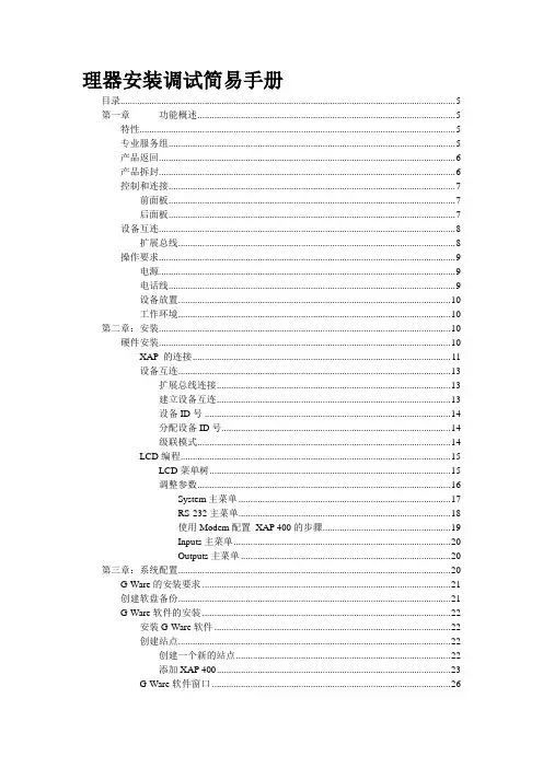
理器安装调试简易手册目录 (5)第一章功能概述 (5)特性 (5)专业服务组 (5)产品返回 (6)产品拆封 (6)控制和连接 (7)前面板 (7)后面板 (7)设备互连 (8)扩展总线 (8)操作要求 (9)电源 (9)电话线 (9)设备放置 (10)工作环境 (10)第二章:安装 (10)硬件安装 (10)XAP 的连接 (11)设备互连 (13)扩展总线连接 (13)建立设备互连 (13)设备ID号 (14)分配设备ID号 (14)级联模式 (14)LCD编程 (15)LCD菜单树 (15)调整参数 (16)System主菜单 (17)RS-232主菜单 (18)使用Modem配置XAP 400的步骤 (19)Inputs主菜单 (20)Outputs主菜单 (20)第三章:系统配置 (20)G-Ware的安装要求 (21)创建软盘备份 (21)G-Ware软件的安装 (22)安装G-Ware软件 (22)创建站点 (22)创建一个新的站点 (22)添加XAP 400 (23)G-Ware软件窗口 (26)矩阵窗口 (28)音频路由 (29)O-Z扩展总线路由 (30)A-H音频处理路由 (30)交叉点电平衰减 (30)输入和输出 (32)输入1-4 (32)创建虚拟参考 (35)NLP(非线性处理) (36)Meters(电平表) (36)NC(回声消除器) (36)Filters(滤波器) (37)激活滤波器 (37)滤波器类型 (37)滤波器主要参数 (38)配置滤波器 (39)Gate(门控) (39)麦克激励 (40)Chairman Override(主席模式) (40)Adaptive Ambient(环境自适应模式) (40)PA Adaptive Mode(PA自适应模式) (40)选通率 (41)保持时间 (41)衰减量 (41)环境电平 (41)衰减率 (41)PA自适应和AEC参考 (41)选择门控组(混音器) (42)指定门控组..................................................... 错误!未定义书签。

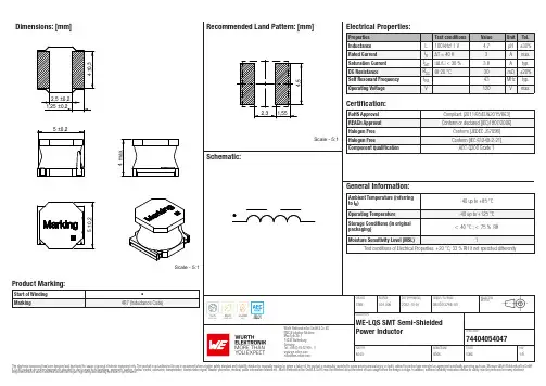
Dimensions: [mm]Scale - 5:174404054047BC74404054047T e m p e r a t u r eT pT L74404054047Cautions and Warnings:The following conditions apply to all goods within the product series of WE-LQS of Würth Elektronik eiSos GmbH & Co. KG:General:•This electronic component is designed and manufactured for use in general electronic equipment.•Würth Elektronik must be asked for written approval (following the PPAP procedure) before incorporating the components into any equipment in fields such as military, aerospace, aviation, nuclear control, submarine, transportation (automotive control, train control, ship control), transportation signal, disaster prevention, medical, public information network etc. where higher safety and reliability are especially required and/or if there is the possibility of direct damage or human injury.•Electronic components that will be used in safety-critical or high-reliability applications, should be pre-evaluated by the customer. •The component is designed and manufactured to be used within the datasheet specified values. If the usage and operation conditions specified in the datasheet are not met, the wire insulation may be damaged or dissolved.•Do not drop or impact the components, the component may be damaged.•Würth Elektronik products are qualified according to international standards, which are listed in each product reliability report. Würth Elektronik does not warrant any customer qualified product characteristics beyond Würth Elektroniks’ specifications, for its validity and sustainability over time.•The responsibility for the applicability of the customer specific products and use in a particular customer design is always within the authority of the customer. All technical specifications for standard products also apply to customer specific products.Product specific:Soldering:•The solder profile must comply with the technical product specifications. All other profiles will void the warranty.•All other soldering methods are at the customers’ own risk.•Strong forces which may affect the coplanarity of the components’ electrical connection with the PCB (i.e. pins), can damage the part, resulting in avoid of the warranty.Cleaning and Washing:•Washing agents used during the production to clean the customer application might damage or change the characteristics of the wire insulation, marking or plating. Washing agents may have a negative effect on the long-term functionality of the product.•Using a brush during the cleaning process may break the wire due to its small diameter. Therefore, we do not recommend using a brush during the PCB cleaning process.Potting:•If the product is potted in the customer application, the potting material may shrink or expand during and after hardening. Shrinking could lead to an incomplete seal, allowing contaminants into the core. Expansion could damage the components. We recommend a manual inspection after potting to avoid these effects.Storage Conditions:• A storage of Würth Elektronik products for longer than 12 months is not recommended. Within other effects, the terminals may suffer degradation, resulting in bad solderability. Therefore, all products shall be used within the period of 12 months based on the day of shipment.•Do not expose the components to direct sunlight.•The storage conditions in the original packaging are defined according to DIN EN 61760-2.•The storage conditions stated in the original packaging apply to the storage time and not to the transportation time of the components. Packaging:•The packaging specifications apply only to purchase orders comprising whole packaging units. If the ordered quantity exceeds or is lower than the specified packaging unit, packaging in accordance with the packaging specifications cannot be ensured. Handling:•Violation of the technical product specifications such as exceeding the nominal rated current will void the warranty.•Applying currents with audio-frequency signals may result in audible noise due to the magnetostrictive material properties.•The temperature rise of the component must be taken into consideration. The operating temperature is comprised of ambient temperature and temperature rise of the component.The operating temperature of the component shall not exceed the maximum temperature specified.These cautions and warnings comply with the state of the scientific and technical knowledge and are believed to be accurate and reliable.However, no responsibility is assumed for inaccuracies or incompleteness.Würth Elektronik eiSos GmbH & Co. KGEMC & Inductive SolutionsMax-Eyth-Str. 174638 WaldenburgGermanyCHECKED REVISION DATE (YYYY-MM-DD)GENERAL TOLERANCE PROJECTIONMETHODChrB.001.0062022-10-01DIN ISO 2768-1mDESCRIPTIONWE-LQS SMT Semi-ShieldedPower Inductor ORDER CODE74404054047SIZE/TYPE BUSINESS UNIT STATUS PAGEImportant NotesThe following conditions apply to all goods within the product range of Würth Elektronik eiSos GmbH & Co. KG:1. General Customer ResponsibilitySome goods within the product range of Würth Elektronik eiSos GmbH & Co. KG contain statements regarding general suitability for certain application areas. These statements about suitability are based on our knowledge and experience of typical requirements concerning the areas, serve as general guidance and cannot be estimated as binding statements about the suitability for a customer application. The responsibility for the applicability and use in a particular customer design is always solely within the authority of the customer. Due to this fact it is up to the customer to evaluate, where appropriate to investigate and decide whether the device with the specific product characteristics described in the product specification is valid and suitable for the respective customer application or not.2. Customer Responsibility related to Specific, in particular Safety-Relevant ApplicationsIt has to be clearly pointed out that the possibility of a malfunction of electronic components or failure before the end of the usual lifetime cannot be completely eliminated in the current state of the art, even if the products are operated within the range of the specifications.In certain customer applications requiring a very high level of safety and especially in customer applications in which the malfunction or failure of an electronic component could endanger human life or health it must be ensured by most advanced technological aid of suitable design of the customer application that no injury or damage is caused to third parties in the event of malfunction or failure of an electronic component. Therefore, customer is cautioned to verify that data sheets are current before placing orders. The current data sheets can be downloaded at .3. Best Care and AttentionAny product-specific notes, cautions and warnings must be strictly observed. Any disregard will result in the loss of warranty.4. Customer Support for Product SpecificationsSome products within the product range may contain substances which are subject to restrictions in certain jurisdictions in order to serve specific technical requirements. Necessary information is available on request. In this case the field sales engineer or the internal sales person in charge should be contacted who will be happy to support in this matter.5. Product R&DDue to constant product improvement product specifications may change from time to time. As a standard reporting procedure of the Product Change Notification (PCN) according to the JEDEC-Standard inform about minor and major changes. In case of further queries regarding the PCN, the field sales engineer or the internal sales person in charge should be contacted. The basic responsibility of the customer as per Section 1 and 2 remains unaffected.6. Product Life CycleDue to technical progress and economical evaluation we also reserve the right to discontinue production and delivery of products. As a standard reporting procedure of the Product Termination Notification (PTN) according to the JEDEC-Standard we will inform at an early stage about inevitable product discontinuance. According to this we cannot guarantee that all products within our product range will always be available. Therefore it needs to be verified with the field sales engineer or the internal sales person in charge about the current product availability expectancy before or when the product for application design-in disposal is considered. The approach named above does not apply in the case of individual agreements deviating from the foregoing for customer-specific products.7. Property RightsAll the rights for contractual products produced by Würth Elektronik eiSos GmbH & Co. KG on the basis of ideas, development contracts as well as models or templates that are subject to copyright, patent or commercial protection supplied to the customer will remain with Würth Elektronik eiSos GmbH & Co. KG. Würth Elektronik eiSos GmbH & Co. KG does not warrant or represent that any license, either expressed or implied, is granted under any patent right, copyright, mask work right, or other intellectual property right relating to any combination, application, or process in which Würth Elektronik eiSos GmbH & Co. KG components or services are used.8. General Terms and ConditionsUnless otherwise agreed in individual contracts, all orders are subject to the current version of the “General Terms and Conditions of Würth Elektronik eiSos Group”, last version available at .Würth Elektronik eiSos GmbH & Co. KGEMC & Inductive SolutionsMax-Eyth-Str. 174638 WaldenburgGermanyCHECKED REVISION DATE (YYYY-MM-DD)GENERAL TOLERANCE PROJECTIONMETHODChrB.001.0062022-10-01DIN ISO 2768-1mDESCRIPTIONWE-LQS SMT Semi-ShieldedPower Inductor ORDER CODE74404054047SIZE/TYPE BUSINESS UNIT STATUS PAGE。

MDMA SERIESMicrominiature connectors with removable crimp contacts ESCC 3401/077 - ESCC 3401/078Features and Benefits•Compliant with ESA specifications•High performance Micropin™ contact system(“twist pin” spring male contact and tubular socket contact)•Removable crimp type contacts •Harnesses length flexibility •Non-Outgassing•Low Size Connectors •Low WeightT ypical Applications•Space equipment•Satellites harnesses and payloads •Avionics / MilitarySpecification•High performance Micro-miniature connectors ESA qualified, for space applications.•Compliant to ESCC specifications 3401/077 Connectors and 3401/078 Removable Crimp Contacts.•Compatible with ESCC 3401/029 MDM Connectors, 3401/041Savers, 3401/032 Accessories and 3401/087 Backshells.•Suitable for use in Space, and high performance military/aerospace applications: Board to Board, Board to Cable or Cable to Cable applications.Quality Level•ESA / ESCC: code 3401 (Flying model).•Qualification reviewed every 2 years.Process Contact and Cable Insertion•Wire stripping.•Cables crimping onto contacts with standard MDMA Crimping tool M22520/2-01 and dedicated locators (to be ordered separately).•Wires cable installed by the end user.T est Retention•A dedicated tool is available to make the retention test of each contacts in the connectors.Process Contact and Cable Extraction•A dedicated tool is available to remove the contacts from the connectors.Options•Optional interfacial seal can be applied for female connectors (to be ordered separately).•Optional captive nuts or float mounting.Packaging•Individual packaging.•T raceability associated as per ESA/ESCC specifications.•Each MDMA connector is sold with a dust cap in individual plastic bag.•Contact extraction tool has to be ordered separately.•Removable contacts (Twist Pin contact technology).•Sizes available: 9, 15, 21, 25, 31, 37 and 51 ways.•Connector 9, 15, 21, 25, 31 and 37 ways, accepted wires size:•1 wire insulated AWG24, AWG26 and AWG28 (external diameter at 0.97mm max).•1 uninsulated solid wire AWG25.•2 wires insulated AWG28 (external diameter at 0.82mm max).•Connector 51 ways, accepted wires size:•1 wire insulated AWG24, AWG26 and AWG28 (external diameter at 0.97mm max).•1 uninsulated solid wire AWG25.•Distance between 2 adjacent contacts: 1.27mm (.050 inch).•Distance between 2 contacts rows: 1.09mm (.043 inch ).Electrical & Mechanical CharacteristicsOur easy build-a-connector concept allows you to mix and match options to create the MDMA you need. T o order, select desired option from each category and place it in the appropriate box.CONNECTOR340107701B MDMA Y 9P -FOShell Finish 01 25.4 µm Ni02 0.7 µm Au over 25.4 µm Ni T ype of Contact P Pin (Male)S Socket (Female)Detail Specification Number Contacts InformationFO Connector without contacts(Contacts must be ordered separately)Fixing OptionNothing: Standard (no hardware)E Captive nut Y Float mountT esting Level Shell Size 9 15 21 25 31 37 51MDMA SeriesPin connection with Nickel Plating Pin connection with Gold PlatingESA/ESCC Specification:ATTACHMENT OPTIONSCaptive Nut (Option E)Floating Mount (Option Y)CONTACT SOCKET – 340107804B (WIRE SIZE AWG 24, 25, 26, 28 OR 2X28)C&K Part Number: C331-8754-000H ESA/ESCC Description:340107803BC&K Part Number: C252-8844-000H ESA/ESCC Description:340107804BNota:Other products available:-Male Contact 340107801B, compatible with wire size AWG 25, 26 or 28.-Female Contact 340107802B, compatible with wire size AWG 25, 26, 28.Cable Crimping1 – Insert wire into contact body.2 – Insert the unit into the crimping tool (selector position 2) with dedicated locator.Crimping tool - Position #2:M22520/2-01 (P/N: C995-0001-584)Contact InsertionInsert contact with wire into rear insulator cavity until positive stop.T o avoid stress onto retention clip, insert contact in the axis (no insertion angle).T o be sure contact is locked securely, pull back lightly on wire or use calibrated test retention tool.MDMA-Retention tool (P/N: C115373-0003).1 – Select contact extraction tool:- Connector size 9 to 37 ->MDMA-Extract tool-01 (P/N: C115373-0006)- Connector size 51 ->MDMA-Extract tool-02 (P/N: C115373-0007)2 – Insert tool tip into contact cavity until tip bottoms against contact shoulder, releasing tine.Hold wire against tool with finger and remove tool and contact.Be careful to put extraction tool in the good position!Each contact cavity has flat area to place tool tip.Connector size 9 to 37Connector size 51Locator for Male Contact:MDMA-Locator-P-01 (P/N: C115373-0001) Locator for Female Contact:MDMA-Locator-S -01(P/N: C115373-0002)Insert the tip of the tool around the Pin contactPush the tool up to the stop with the front face of the connector Pull back lightly on wire to be sure contact is locked securelyUse Retention Test Tool - P/N C115373-0003This tool is equipped with 2 test tips at the ends for use with Pin and Socket connectors .It is delivered with:• 2 protective caps• 1 adaptator for connectors MDMA-51S1 calibration certificate referring to applicable force and travel If necessary, we can perform the calibration of tools already in service. Use P/N C115373-0003 CA for a quote .MDMA Connector with Pin Contacts:MDMA Connector with Socket Contacts:Insert the tip of the tool inside the Socket contactPush the tool up to the stop with the front face of the connectorPull back lightly on wire to be sure contact is locked securelyMALE SCREWLOCKCRIMPING TOOLLOCATOREXTRACTION TOOLTEST RETENTION TOOLFor the complete range of accessories and details, consult our MDM accessories datasheet.ASIAT el: +852.3713.5288EUROPET el: +33.1.60.24.51.51AMERICAS T el: +1.617.969.3700CONTACTS DESCRIPTION AND C&K PART NUMBERS*T o be preferred. Designed for all wires combination.。

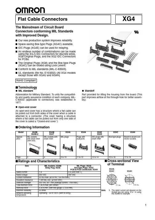
1XG4Flat Cable ConnectorsThe Mainstream of Circuit BoardConnectors conforming MIL Standards with Improved Design.■Our new production system improves reliability.■Space-saving Box-type Plugs (XG4C) available.■IDC Plugs (XG4E) can be used for relaying.■An endless number of combinations can be madeusing the XG-5 IDC Connectors for discrete wires,XG8 Original Plugs, and the XG2 IDC Connectors for PCBs.■The Original Plugs (XG8) and the Box-type Plugs (XG4C) can be locked using Lock Levers.■Conform to MIL standards (MIL-C-83503).■UL standards (file No. E103202) (All XG4 models except those with XG4U and XG4H)■Terminologyz MIL standardAbbreviation for Military Standard. To unify the compatibil-ity and quality assurance condition of each company, MIL-C-83503 (applicable to connectors) was established in 1977.z Open-end coverAn open-end cover has a structure where a flat cable can be pulled out from both sides of the cover when a cable is attached to a connector. (The cover having a structure where a flat cable can be pulled out from only one side of the cover is called a "Closed-end cover.")z StandoffPart provided for lifting the housing from the board (This part improves airflow at the through-hole for better assem-bly.)■Ordering InformationRoHS CompliantItemMIL Sockets: XG4M Relay Plug: XG4EMIL Plugs: XG4A Box-type Plugs: XG4CPCB-to-PCB Connectors: XG4HRated current 1 A 3 A (See note 1.)Rated voltage250 VAC 300 VAC Contact resistance 20 m Ω max. (at 20 mV, 100 mA max.)Insulation resistance 1,000 M Ω min. (at 500 VDC)Dielectric strength 500 VAC for 1 min (leakage current: 1 mA max.)Note:1.The rated current will depend on theSocket you are using. It is 1 A using the XG4M for example.Total insertion force 1.96 N max. per contactRemoval force 0.39 N min. (with test gauge, t= 0.64 mm)Insertion durability 50 timesAmbient operating temperatureOperating: −55 to 105°C (with no icing )of Terminal2Flat Cable Connectors XG4■Materials and Finish■Applicable WiresFor pressing1.27-mm pitch flat cable incorporating AWG28 wires•UL2651(standard cable)•UL20012 (folding cable)•UL20028 (color-coded cable)■Mating Combinations for XG4 and XG5ItemMIL Plugs: XG4A Box-type Plugs: XG4C Relay Plugs: XG4E (Strain Relief: XG4S)MIL Sockets: XG4M (Strain Relief: XG4T)Board-to-boardConnector: XG4H Housings Fiber-glass reinforced PBT resin (UL94V-0)/black Covers ---Polyamide resin (UL94V-0)/black Fiber-glass reinforced PBTresin (UL94V-0)/black---Contacts Mating end Brass/nickel base, 0.15-µm gold platingPhosphor bronze/nickel base, 0.15-µm gold platingTerminal Press fit Brass/nickel base, 2.0-µm tin platingPhosphor bronze/nickel base, 2.0-µm tin platingStrain Reliefs ---Polyamide resin (UL94V-0)/black Fiber-glass reinforced PBTresin (UL94V-0)/black---XG4M-U MIL Connectors with Socket Locks■Dimensions(Unit: mm)■Ordering InformationNote:1.With open-end cover.2.Strain Relief sold separately.3.Polarity guide pitch is 22.86 mm.XG4UXG4M-XG4M-■Mating Diagrams for XG4MFlat Cable Connectors XG434Flat Cable Connectors XG4XG4M MIL Sockets■Dimensions(Unit: mm)XG4M-@@30-T (XG4M-@@30 + XG4T-@@04)XG4M-@@31-T (XG4M-@@31 + XG4T-@@04)MIL Socket and Strain Relief Sets■Ordering InformationNote:1.With open-end cover.2.Strain Relief sold separately.3.Polarity guide pitch is 22.86 mmStrain reliefOpen-end coverTriangular markPolarizing Key slot (2) (Not on models with less than 14 contacts.)Polarity guide Polarizing Key slot (1)XG4M-@@30 (one polarizing guide)XG4M-@@31 (all others)XG4T-@@04Strain ReliefDimensionsNo. of contactsDimensions (mm)A B 1017.310.161422.315.241624.917.782030.022.862637.630.483042.735.563447.740.644055.448.265068.160.966080.873.666485.878.74No. of contactsNo. of polarity guidesSocket and Strain Relief Set (See note 1.)Socket with Open-end Cover (See note 2.)Strain Relief for the XG4M100XG4M-1031-T XG4M-1031XG4T -10041XG4M-1030-T XG4M-1030141XG4M-1430-T XG4M-1430XG4T -1404161XG4M-1630-T XG4M-1630XG4T -1604201XG4M-2030-T XG4M-2030XG4T -2004261XG4M-2630-T XG4M-2630XG4T -2604301XG4M-3030-T XG4M-3030XG4T -3004341XG4M-3430-T XG4M-3430XG4T -3404401XG4M-4030-T XG4M-4030XG4T -4004501XG4M-5030-T XG4M-5030XG4T -50042 (See note 3.)XG4M-5031-T XG4M-5031601XG4M-6030-T XG4M-6030XG4T -60042 (See note 3.)XG4M-6031-T XG4M-6031641XG4M-6430-TXG4M-6430XG4T -64042 (See note 3.)XG4M-6431-TXG4M-6431Flat Cable Connectors XG45XG4A MIL Plugs with Long Locks (MIL Standards)■Dimensions(Unit: mm)Straight DIP terminals Right-angle DIP terminals0.635 × 0.6350.635 × 0.635Straight DIP terminals Right-angle DIP terminalsTwo, 2.6 dia.(M3 tapping screw hole)Two, 2.65 dia.Triangular markPolarizing Key slot (not on models with less than 14 contacts)Polarity slotPolarizing Key slotMounting view (bottom view)Right-angle terminals 0.8 dia. (DIP terminals)0Two, 2.8 dia. (M2.6)Two, 3.2 dia. (M3 tapping screw hole)Straight terminals0.8 dia. (DIP terminals)0Two, 3.2 dia.(M3 tapping screw hole)XG4A-@@31/-@@71 (With straight DIP terminals)XG4A-@@34/-@@74 (With right-angle DIP terminals)DimensionsNote:See page 16 for details on the availability (10-contact Connectors)and pitch (with 50, 60, or 64-contact Connectors) of polarity slot s.No. of contacts Dimensions (mm)A B C D E F 1032.017.510.1621.827.946.41437.122.615.2426.933.051.51639.625.217.7829.535.654.12044.730.222.8634.540.659.12652.337.930.4842.248.366.83057.442.935.5647.253.371.83462.548.040.6452.358.476.94070.155.648.2659.966.084.55082.868.360.9672.678.797.26095.581.073.6685.391.4109.964100.686.178.7490.496.5115.06Flat Cable Connectors XG4■Ordering InformationUse in Combination with Strain-relief Sockets.Note:Polarizing slot pitch is 22.86 mm.No. ofcontactsNo. of polarizing slotsPlugs with straight DIP terminalsPlugs with right-angle DIP terminals100XG4A-1071XG4A-10741XG4A-1031XG4A-1034141XG4A-1431XG4A-1434161XG4A-1631XG4A-1634201XG4A-2031XG4A-2034261XG4A-2631XG4A-2634301XG4A-3031XG4A-3034341XG4A-3431XG4A-3434401XG4A-4031XG4A-4034501XG4A-5031XG4A-50342 (See note.)XG4A-5071XG4A-5074601XG4A-6031XG4A-60342 (See note.)XG4A-6071XG4A-6074641XG4A-6431XG4A-64342 (See note.)XG4A-6471XG4A-6474Flat Cable Connectors XG47XG4A MIL Plugs with Short Locks■Dimensions(Unit: mm)Straight DIP terminals Right-angle DIP terminals0.635 × 0.6350.635 × 0.635Straight DIP terminals Right-angle DIP terminalsMounting holes (bottom view)Right-angle terminalsStraight terminalsTwo, 2.6 dia.(M3 tapping screw hole)Two, 2.65 dia.Polarizing Key slot (not on models with less than 14 contacts)Triangular markPolarity slotPolarizing Key slot0.8 dia. (DIP terminals)00.8 dia. (DIP terminals)Two, 2.8 dia. (M2.6)Two, 3.2 dia. (M3 tapping screw hole)Two, 3.2 dia. (M3 tapping screw hole)XG4A-@@32/-@@72 (With straight DIP terminals)XG4A-@@35/-@@75 (With right-angle DIP terminals)DimensionsNote:See page 16 for details on the availability (10-contact Connectors)and pitch (with 50, 60, or 64-contact Connectors) of polarity slot s.No. ofcontacts Dimensions (mm)A B C D E F 1032.017.510.1621.827.940.41437.122.615.2426.933.045.51639.625.217.7829.535.648.02044.730.222.8634.540.653.12652.337.930.4842.248.360.73057.442.935.5647.253.365.83462.548.040.6452.358.470.94070.155.648.2659.966.078.55082.868.360.9672.678.791.26095.581.073.6685.391.4103.964100.686.178.7490.496.5109.08Flat Cable Connectors XG4■Ordering InformationUse in combination with sockets without strain-relief.Note:Polarizing slot pitch is 22.86 mm.No. ofcontactsNo. of polarizing slotsPlugs with straight DIP terminalsPlugs with right-angle DIP terminals100XG4A-1072XG4A-10751XG4A-1032XG4A-1035141XG4A-1432XG4A-1435161XG4A-1632XG4A-1635201XG4A-2032XG4A-2035261XG4A-2632XG4A-2635301XG4A-3032XG4A-3035341XG4A-3432XG4A-3435401XG4A-4032XG4A-4035501XG4A-5032XG4A-50352 (See note.)XG4A-5072XG4A-5075601XG4A-6032XG4A-60352 (See note.)XG4A-6072XG4A-6075641XG4A-6432XG4A-64352 (See note.)XG4A-6472XG4A-6475Flat Cable Connectors XG49XG4A MIL Plugs without Lock Levers (Lock Leversmounted later)■Dimensions(Unit: mm)Straight DIP terminals Right-angle DIP terminals0.635 × 0.6350.635 × 0.635Straight DIP terminals Right-angle DIP terminalsT wo, 2.6 dia.(M3 tapping screw hole)Two, 2.65 dia.Polarizing Key slot (not on models with less than 14 contacts)Polarity slotPolarizing Key slotTriangular markMounting holes (bottom view)Right-angle terminalsStraight terminals0.8 dia. (DIP terminals)00.8 dia. (DIP terminals)0T wo, 2.8 dia. (M2.6)T wo, 3.2 dia. (M3 tapping screw hole)T wo, 3.2 dia.(M3 tapping screw hole)C ±0.12D ±0.15XG4A-@@33/-@@73 (With straight DIP terminals)XG4A-@@36/-@@76 (With right-angle DIP terminals)DimensionsNote:See page 16 for details on the availability (10-contact Connectors)and pitch (with 50, 60, or 64-contact Connectors) of polarizing slot s.No. of contacts Dimensions (mm)A B C D E 1032.017.510.1621.827.91437.122.615.2426.933.01639.625.217.7829.535.62044.730.222.8634.540.62652.337.930.4842.248.33057.442.935.5647.253.33462.548.040.6452.358.44070.155.648.2659.966.05082.868.360.9672.678.76095.581.073.6685.391.464100.686.178.7490.496.510Flat Cable Connectors XG4■Ordering InformationNote:Polarity slot pitch is 22.86 mm.Lock Levers•This series of Connectors allows you to attach Lock Levers on Right-angle Terminal Plugs after automated soldering is completed.•Lock Levers can be easily mounted simply by manually pushing them in.Note:The left and right Lock Levers are identical. One pair is neededfor each Plug.Attachment after Soldering•Long Levers interfere with automated mounting.•Long Levers are in the way when boards are packed.↓•These problems are resolved using Connectors with Long Levers that can be attached after soldering is completed.No. ofcontactsNo. of polarizing slotsPlugs with straight DIP terminalsPlugs right-angle DIP terminals100XG4A-1073XG4A-10761XG4A-1033XG4A-1036141XG4A-1433XG4A-1436161XG4A-1633XG4A-1636201XG4A-2033XG4A-2036261XG4A-2633XG4A-2636301XG4A-3033XG4A-3036341XG4A-3433XG4A-3436401XG4A-4033XG4A-4036501XG4A-5033XG4A-50362 (See note.)XG4A-5073XG4A-5076601XG4A-6033XG4A-60362 (See note.)XG4A-6073XG4A-6076641XG4A-6433XG4A-64362 (See note.)XG4A-6473XG4A-6476TypeModelLong Lock Levers XG4Z-0010Short Lock LeversXG4Z-0011XG4Z-0010 Long Lock Lever XG4Z-0011 Short Lock LeverFlat Cable Connectors XG411XG4A 2-tier Plugs with Long Lock■Dimensions(Unit: mm)■Ordering InformationNote:1.Set containing a stopper, mounting screw (assembled withwasher) and nut.Screw size: M2.6 x 20 mm2.Polarizing slot pitch is 22.86 mm.No. of contactsNo. of polarizing slotsModelNo. of contactsNo. of polarity slotsModel10 × 20XG4A-1079-A 40 × 21XG4A-4039-A 1XG4A-1039-A 14 × 21XG4A-1439-A 50 × 21XG4A-5039-A 16 × 21XG4A-1639-A 2 (See note 2.)XG4A-5079-A 20 × 21XG4A-2039-A 60 × 21XG4A-6039-A 26 × 21XG4A-2639-A 2 (See note 2.)XG4A-6079-A 30 × 21XG4A-3039-A 64 × 21XG4A-6439-A 34 × 21XG4A-3439-A2 (See note 2.)XG4A-6479-AMounting holes (bottom view)0.635 × 0.635Two, 2.65 dia.Stopper (For connecting top and bottom connectors)T wo, 2.65 dia.Triangular markPolarizing Key slot (not on models with less than 14 contacts)Polarity slotPolarizing Key slot (not on the XG4A- 1039-A)0.8 dia.0Two, 2.8 dia.±0.12D ±0.152.54±0.05C ±0.12 2.54±0.052.54±0.052.54±0.05XG4A-@@39-A/-@@79-A (With long locks and right-angle DIP terminals)DimensionsNote:Polarizing slot pitch is 22.86 mm for 50-, 60-,and 64-contact Connectors.No. of contacts Dimensions (mm)A B CDE 10 × 232.017.510.1621.846.414 × 237.122.615.2426.951.516 × 239.625.217.7829.554.120 × 244.730.222.8634.559.126 × 252.337.930.4842.266.830 × 257.442.935.5647.271.834 × 262.548.040.6452.376.940 × 270.155.648.2659.984.950 × 282.868.360.9672.697.260 × 295.581.073.6685.3109.964 × 2100.686.178.7490.4115.012Flat Cable Connectors XG4■Mounting Example ■2-tier Plug Features•Recommended for high-density mounting.•MIL-compliant cable ensures faster delivery times and lower cost than half-pitch board cable. The 2.54-mm pitch simplifies pattern-ing.■PrecautionsCorrect UseMounting•Be sure to anchor the board with screws before mounting.•Note that a Polarizing Key cannot be mounted on the lower Plug.Connecting the Socket•Before connecting the XG4M with Strain Relief, remove as much slack from the cable as possible. Insert as shown below.•Attach the Semi-cover before connecting the XG5M-N. It is not pos-sible to use the Hood Cover.Soldering•Automated Soldering Conditions (Jet Flow)1.Soldering temperature: 250 ±5°C 2.Continuous soldering time: Within 5 sXG4MT riangular markCable markCable numberSocket (mating side)Right-angle terminals (terminal side)XG4AT riangular mark (back)Lower connector Upper connector■Applicable SocketsNote:e with the supplied Strain Relief.e with the supplied Semi-cover. Hood Cover cannot be used.3.Polarity slot pitch is 22.86 mm.No. of contacts No. of polarity slots ModelXG4M for flat cable(See note 1.)XG5M-N for discrete wire (See note 2.)10 × 20XG4A-1079-A XG4M-1031XG5M-103@-N 1XG4A-1039-A XG4M-1030XG5M-103@-N 14 × 21XG4A-1439-A XG4M-1430XG5M-143@-N 16 × 21XG4A-1639-A XG4M-1630XG5M-163@-N 20 × 21XG4A-2039-A XG4M-2030XG5M-203@-N 26 × 21XG4A-2639-A XG4M-2630XG5M-263@-N 30 × 21XG4A-3039-A XG4M-3030XG5M-303@-N 34 × 21XG4A-3439-A XG4M-3430XG5M-343@-N 40 × 21XG4A-4039-A XG4M-4030XG5M-403@-N 50 × 21XG4A-5039-A XG4M-5030XG5M-503@-N2 (See note 3.)XG4A-5079-A XG4M-503160 × 21XG4A-6039-A XG4M-6030XG5M-603@-N 2 (See note 3.)XG4A-6079-A XG4M-603164 × 21XG4A-6439-A XG4M-6430XG5M-643@-N2 (See note 3.)XG4A-6479-A XG4M-6431■Cable Number and Contact PositionCable and Corresponding Contact Number The contact numbers are not marked on the Con-nector. Use the triangular mark as a guide when wiring and designing circuit boards.For the cable number, count starting from the cable mark side as shown below.Flat Cable Connectors XG413XG4E Relay Plugs■Dimensions(Unit: mm)(Long locks)(Short locks)0.635 × 0.635Open-end cover0.635 × 0.635Strain ReliefTwo, 2.6 dia.(M3 tapping screw hole)Two, 2.65 dia.TriangularmarkPolarizing Key slot(Not on models with less than 14 contacts.)Polarity slot Polarizing Key slot DimensionsNote:See the following page for details on the availability (10-contact Connectors) and pitch(with 50, 60, or 64-contact Connectors) of polarity slot s.No. of contactsDimensions (mm)ABCDEF GLong LockShort Lock 1032.017.510.1621.827.946.440.416.91437.122.615.2426.933.051.545.522.01639.625.217.7829.535.654.148.024.62044.730.222.8634.540.659.153.129.62652.337.930.4842.248.366.860.738.03057.442.935.5647.253.371.865.842.33462.548.040.6452.358.476.970.947.44070.155.648.2659.966.084.578.555.05082.868.360.9672.678.797.291.267.76095.581.073.6685.391.4109.9103.980.464100.686.178.7490.496.5115.0109.085.514Flat Cable Connectors XG4■Ordering InformationRelay PlugsUse Long-lock Plugs together with Strain-relief Sockets, and use Short-lock Plugs together with Non-strain-relief Sockets.Note:1.Strain Relief sold separately.2.Polarity slot pitch is 22.86 mm.■Cable Number and Contact PositionNo. of contactsNo. of polarizing slotsLong-lock Plugs with Open-end Covers (See note 1.)Short-lock Plugs with Open-end Covers (See note 1.)Strain Reliefs for XG4E100XG4E-1071XG4E-1072XG4S-10041XG4E-1031XG4E-1032141XG4E-1431XG4E-1432XG4S-1404161XG4E-1631XG4E-1632XG4S-1604201XG4E-2031XG4E-2032XG4S-2004261XG4E-2631XG4E-2632XG4S-2604301XG4E-3031XG4E-3032XG4S-3004341XG4E-3431XG4E-3432XG4S-3404401XG4E-4031XG4E-4032XG4S-4004501XG4E-5031XG4E-5032XG4S-50042 (See note 2.)XG4E-5071XG4E-5072601XG4E-6031XG4E-6032XG4S-60042 (See note 2.)XG4E-6071XG4E-6072641XG4E-6431XG4E-6432XG4S-64042 (See note 2.)XG4E-6471XG4E-6472Socket (mated side)Right-angle T erminal Plug (terminal side)Plug (XG4E)Straight T erminal Plug (terminal side)T riangular markCable mark Cable No.XG4A XG4CT riangular mark (back)T riangular markT riangular markCable mark Cable No.Cable and Corresponding Contact NumberThe contact numbers are not marked on the Connector. Use the triangular mark as a guide when wiring and designing circuit boards.For the cable number, count starting from the cable mark side as shown on the right.Flat Cable Connectors XG415XG4C Box-type Plugs■Dimensions(Unit: mm)■Ordering InformationNote:1.Polarizing slot pitch is 22.86 mm.2.The Box-type Plug can be locked using Lock Lever II (sold separately). (See XG4Z-0002 on page 19.)No. of contactsNo. of polarizing slotsPlugs with straight DIP terminalsPlugs with right-angle DIP terminals100XG4C-1071XG4C-10741XG4C-1031XG4C-1034141XG4C-1431XG4C-1434161XG4C-1631XG4C-1634201XG4C-2031XG4C-2034261XG4C-2631XG4C-2634301XG4C-3031XG4C-3034341XG4C-3431XG4C-3434401XG4C-4031XG4C-4034501XG4C-5031XG4C-50342 (See note 1.)XG4C-5071XG4C-5074601XG4C-6031XG4C-60342 (See note 1.)XG4C-6071XG4C-6074641XG4C-6431XG4C-64342 (See note 1.)XG4C-6471XG4C-6474Triangular markPolarizing Key slot (Not on models with less than 14 contacts.)Polarity slot Polarizing Key slotRight-angle DIP terminalsStraight DIP terminals(Right-angle DIP terminals)(Straight DIP terminals)Mounting holes (bottom view)0.8 dia.0Straight DIP terminalsRight-angle DIP terminals 0.8 dia.0C ±0.12XG4C-@@31/-@@71(With straight DIP terminals)XG4C-@@34/-@@74(With right-angle DIP terminals)DimensionsNote:See the following page for details onthe availability (10-contact Connec-tors) and pitch (with 50, 60, or 64-con-tact Connectors) of polarity slot s.No. of contacts Dimensions (mm)A B C 1020.017.510.161425.122.615.241627.625.217.782032.730.222.862640.337.930.483045.442.935.563450.548.040.644058.155.648.265070.868.360.966083.581.073.666488.686.178.74■Mating Diagrams for XG4M■Polarity Slot and Polarizing Key Slot Number and PositionClassification No. of contacts10 contacts14 contacts16 to 40 contacts50 to 64 contactsXG4MMIL SocketXG4M-1031XG4M-1030XG4M-1430XG4M-1630 to XG4M-6430---XG4M-5031, XG4M-6031, XG4M-6431XG4AMIL PlugXG4EIDC PlugXG4A-107@XG4E-107@XG4A-103@XG4E-103@XG4A-143@XG4E-143@XG4A-163@ to XG4A-643@XG4E-163@ to XG4E-643@---XG4A-507@, XG4A-607@, XG4A-647@XG4E-507@, XG4E-607@, XG4E-647@XG4CBox-type PlugXG4C-107@XG4C-103@XG4C-143@XG4C-163@ to XG4C-643@---XG4C-507@, XG4C-607@, XG4C-647@No. of polarizingguides (PolarizingSlots)011112 (H = 22.86 mm)No. of PolarizingKey slot (PolarizingKey Slots)10122XG4U + XG4M + XG4C XG4T + XG4M + XG4A XG4T + XG4M + XG4C + Lock LeverPolarizing Key slotPolarizing guidePolarizingKey slotPolarizing slotPolarizing slotPolarizing slot16Flat Cable Connectors XG4Flat Cable Connectors XG417XG4H Board-to-Board Sockets■Dimensions(Unit: mm)■Ordering InformationNote:Polarizing guide pitch is 22.86 mm.XG4H-@@31/-@@71(With straight DIP terminals)XG4H-3431-1 XG4H-4031-1(With straight DIP terminals)*Sockets with model numbers end-ing in -1 are available only with 34or 40 contacts (provide kinked ter-No. of contactsNo. of polarizing slotsSockets with straight DIP terminals101XG4H-1031141XG4H-1431161XG4H-1631201XG4H-2031261XG4H-2631301XG4H-3031341XG4H-3431-1401XG4H-4031-1501XG4H-50312 (See note.)XG4H-5071601XG4H-60312 (See note.)XG4H-6071641XG4H-64312 (See note.)XG4H-6471■Mating Diagrams for XG4H18Flat Cable Connectors XG4Flat Cable Connectors XG419■Tools and Accessories (Sold Separately)XG4Z-0004 Polarizing KeyPolarity guides and slots can be used by themselves to help prevent reverse inser-tion. Use the Polarizing Key as well for best results.Note:Each XG4Z-0004 has 4 PolarizingKeys.XG4Z-0005 Coding Pin(T o prevent erroneous insertion)The Coding Pin is used to prevent confu-sion when many Connectors with the same number of contacts are lined up. It can also be used to prevent reverse insertion when using Connectors without a shroud like the XG8 Unshrouded Plug. The Coding Pin can also be used with XC5, and XC6 DIN Connectors as well as with XG5 Discrete-wire IDC Connectors.Note:1. A contact with a Coding Pin in-serted cannot be used.2.Each XG4Z-0005 has 4 Polarizing Keys.XY2E-0002 Contact Cutting DriverThe Contact Cutting Driver is used to cut (twist off) a contact on the mating Plug when using an XG4Z-0005 Coding Pin.■PrecautionsCorrect Use•Automated Soldering Conditions (Jet Flow)1.Soldering temperature: 250 ±5°C2.Continuous soldering time: Within 5 s•SolderingSolder-mount the XG4A with the lock levers fully closed or fully open.Solder-mounting the XG4A with the lock lever half-open may cause play in lock lever due to thermal deformation of the housing.•StorageIf the lock levers of the XG4A or XG4E con-nector are left at an intermediate position for a long time, they may get to feel loose in operation due to deterioration of the plastic part. When the lock levers are not used,store the plug with the lock levers fullyclosed or fully open.Material: PBT resin(UL94V-0)/whiteHow to useInsertT wistPolarizing KeyPolarizing Key slotMaterial: PBT resin (UL94V-0)/whiteHow to useT wistInsertT wistModelXG4Z-0004XG4Z-0005XY2E-0002How to useTwistInsert the plug contact into the groove on the Driver, and twist off the contact from the base.Material: Polyamide resin (UL94V-2)/natural Lock Lever TabXG4MPolarity guide holeXG8BMaterial: Polyamide resin (UL94V-2)/naturalXG4MXG4CInsert the tab on the Lock Lever into the guide hole.Lock Lever for XG8B and XG8W Plugs (With Right-angle Terminals)XG5Z-0002Use to lock Unshrouded Plugs (for XG8B and XG8W Plugs with right-angle terminals).Lock Lever II for XG4C PlugsXG4Z-0002Use to lock XG4C Box-type Plugs.ModelXG5Z-0002XG4Z-0002。
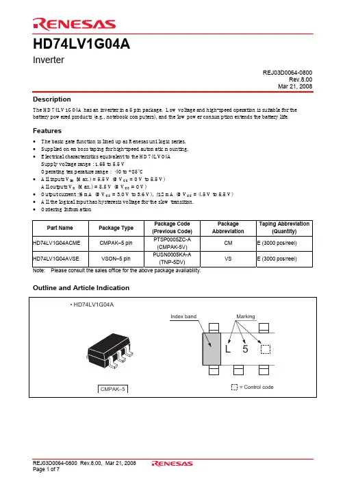
HD74LV1G04AInverterREJ03D0064-0800Rev.8.00 Mar 21, 2008DescriptionThe HD74LV1G04A has an inverter in a 5 pin package. Low voltage and high-speed operation is suitable for the battery powered products (e.g., notebook computers), and the low power consumption extends the battery life.Features• The basic gate function is lined up as Renesas uni logic series. • Supplied on emboss taping for high-speed automatic mounting. • Electrical characteristics equivalent to the HD74LV04A Supply voltage range : 1.65 to 5.5 VOperating temperature range : –40 to +85°C• All inputs V IH (Max.) = 5.5 V (@V CC = 0 V to 5.5 V) All outputs V O (Max.) = 5.5 V (@V CC = 0 V)• Output current ±6 mA (@V CC = 3.0 V to 3.6 V), ±12 mA (@V CC = 4.5 V to 5.5 V) • All the logical input has hysteresis voltage for the slow transition. • Ordering InformationPart NamePackage TypePackage Code (Previous Code) Package AbbreviationTaping Abbreviation(Quantity) HD74LV1G04ACME CMPAK–5 pinPTSP0005ZC-A(CMPAK-5V) CM E (3000 pcs/reel) HD74LV1G04AVSE VSON–5 pinPUSN0005KA-A(TNP-5DV)VSE (3000 pcs/reel)Note: Please consult the sales office for the above package availability.Outline and Article IndicationOutline and Article IndicationFunction TableInput A Output YH LL H H : High levelL : Low levelPin ArrangementAbsolute Maximum RatingsItem Symbol Ratings Unit Test ConditionsSupply voltage range V CC –0.5 to 7.0 VInput voltage range *1V I –0.5 to 7.0 V–0.5 to V CC + 0.5 Output : H or LOutput voltage range *1, 2 V O –0.5 to 7.0 VV CC : OFFInput clamp current I IK –20 mA V I < 0 Output clamp current I OK ±50 mA V O < 0 or V O > V CC Continuous output current I O ±25 mA V O = 0 to V CC Continuous current through V CC or GNDI CC or I GND ±50 mAMaximum power dissipationat Ta = 25°C (in still air) *3P T 200 mW Storage temperature Tstg–65 to 150°CNotes: The absolute maximum ratings are values, which must not individually be exceeded, and furthermore no twoof which may be realized at the same time.1. The input and output voltage ratings may be exceeded if the input and output clamp-current ratings areobserved.2. This value is limited to 5.5 V maximum.3. The maximum package power dissipation was calculated using a junction temperature of 150°C.Recommended Operating ConditionsItem Symbol Min Max Unit ConditionsSupply voltage range V CC 1.65 5.5 V Input voltage range V I 0 5.5 V Output voltage range V O 0 V CC V— 1 V CC = 1.65 to 1.95 V — 2 V CC = 2.3 to 2.7 V— 6 V CC = 3.0 to 3.6 V I OL— 12 V CC = 4.5 to 5.5 V— –1 V CC = 1.65 to 1.95 V — –2 V CC = 2.3 to 2.7 V— –6 V CC = 3.0 to 3.6 V Output current I OH— –12 mAV CC = 4.5 to 5.5 V 0 300 V CC = 1.65 to 1.95 V 0 200 V CC = 2.3 to 2.7 V0 100 V CC = 3.0 to 3.6 V Input transition rise or fall rate ∆t / ∆v 0 20 ns / VV CC = 4.5 to 5.5 V Operating free-air temperatureT a –40 85 °CNote: Unused or floating inputs must be held high or low.• Ta = –40 to 85°CItem Symbol V CC (V) * Min Typ Max Unit Test condition1.65 to 1.95 V CC ×0.75 — —2.3 to 2.7 V CC ×0.7 — —3.0 to 3.6 V CC ×0.7 — — V IH4.5 to5.5 V CC ×0.7 — —1.65 to 1.95 — — V CC ×0.252.3 to 2.7 — — V CC ×0.33.0 to 3.6 — — V CC ×0.3 Input voltage V IL4.5 to5.5 — — V CC ×0.3 V1.8 — 0.25 —2.5 — 0.30 —3.3 — 0.35 —Hysteresis voltage V H 5.0 — 0.45 — V V T + – V T –Min to Max V CC –0.1 — — I OH = –50 µA1.65 1.4 — — I OH = –1 mA2.3 2.0 — —I OH = –2 mA 3.0 2.48 — —I OH = –6 mA V OH4.5 3.8 — —I OH = –12 mAMin to Max — — 0.1I OL = 50 µA 1.65 — — 0.3 I OL = 1 mA 2.3 — — 0.4 I OL = 2 mA 3.0 — — 0.44I OL = 6 mAOutput voltageV OL4.5 — — 0.55 VI OL = 12 mA Input current I IN0 to 5.5 — — ±1 µA V IN = 5.5 V or GNDQuiescent supply current I CC 5.5 — — 10 µAV IN = V CC or GND,I O = 0Output leakage currentI OFF 0 — — 5 µA V IN or V O = 0 to 5.5 V Input capacitanceC IN 3.3 — 3.0 — pF V IN = V CC or GNDNote: For conditions shown as Min or Max, use the appropriate values under recommended operating conditions.• V CC = 1.8 ± 0.15 VTa = 25°C Ta = –40 to 85°CItem Symbol Min Typ Max Min Max UnitTestConditions FROM (Input) TO (Output)— 12.6 22.0 1.0 24.0 C L = 15 pF Propagation delay time t PLHt PHL — 19.7 33.0 1.0 36.0 nsC L = 50 pFAY• V CC = 2.5 ± 0.2 VTa = 25°C Ta = –40 to 85°CItem Symbol Min Typ Max Min Max UnitTestConditions FROM (Input) TO (Output)— 7.0 11.7 1.0 14.0 C L = 15 pF Propagation delay time t PLHt PHL — 10.5 15.5 1.0 18.0 nsC L = 50 pFAY• V CC = 3.3 ± 0.3 VTa = 25°C Ta = –40 to 85°CItem Symbol Min Typ Max Min Max UnitTestConditions FROM (Input) TO (Output)— 5.0 7.1 1.0 8.5 C L = 15 pF Propagation delay time t PLHt PHL — 7.5 10.6 1.0 12.0 nsC L = 50 pFAY• V CC = 5.0 ± 0.5 VTa = 25°C Ta = –40 to 85°CItem Symbol Min Typ Max Min Max UnitTestConditions FROM (Input) TO (Output)— 3.8 5.5 1.0 6.5C L = 15 pF Propagation delay time t PLH t PHL— 5.3 7.5 1.0 8.5nsC L = 50 pFAYOperating Characteristics• C L = 50 pFTa = 25°CItem Symbol V CC (V)Min Typ MaxUnit Test Conditions3.3 — 8.5 —Power dissipationcapacitanceC PD5.0 — 10.0 —pFf = 10 MHzTest CircuitWaveformsPackage DimensionsRefer to "/en/network " for the latest and detailed information.Renesas Technology America, Inc.450 Holger Way, San Jose, CA 95134-1368, U.S.A Tel: <1> (408) 382-7500, Fax: <1> (408) 382-7501Renesas Technology Europe LimitedDukes Meadow, Millboard Road, Bourne End, Buckinghamshire, SL8 5FH, U.K.Tel: <44> (1628) 585-100, Fax: <44> (1628) 585-900Renesas Technology (Shanghai) Co., Ltd.Unit 204, 205, AZIACenter, No.1233 Lujiazui Ring Rd, Pudong District, Shanghai, China 200120Tel: <86> (21) 5877-1818, Fax: <86> (21) 6887-7858/7898Renesas Technology Hong Kong Ltd.7th Floor, North Tower, World Finance Centre, Harbour City, Canton Road, Tsimshatsui, Kowloon, Hong Kong Tel: <852> 2265-6688, Fax: <852> 2377-3473Renesas Technology Taiwan Co., Ltd.10th Floor, No.99, Fushing North Road, Taipei, Taiwan Tel: <886> (2) 2715-2888, Fax: <886> (2) 3518-3399Renesas Technology Singapore Pte. Ltd.1 Harbour Front Avenue, #06-10, Keppel Bay Tower, Singapore 098632 Tel: <65> 6213-0200, Fax: <65> 6278-8001Renesas Technology Korea Co., Ltd.Kukje Center Bldg. 18th Fl., 191, 2-ka, Hangang-ro, Yongsan-ku, Seoul 140-702, Korea Tel: <82> (2) 796-3115, Fax: <82> (2) 796-2145Renesas Technology Malaysia Sdn. BhdUnit 906, Block B, Menara Amcorp, Amcorp Trade Centre, No.18, Jln Persiaran Barat, 46050 Petaling Jaya, Selangor Darul Ehsan, Malaysia Tel: <603> 7955-9390, Fax: <603> 7955-9510RENESAS SALES OFFICES。
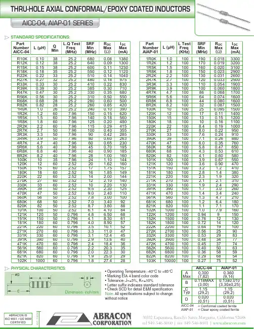
|||||||||||||||Dimension: inch/mmAIAP-01 = Clear epoxy coated ferritePart L (µH)Q L.Q Test SRF R DC I DC Part L (µH)L TestSRF R DC I DC Number Min Freq Min Max Max Number FreqMin Max Max AICC-04(MHz)(MHz) Ω (mA)( )( )AIAP-01(KHz)(MHz)Ω (mA)R10K 0.103825.26800.0813801R0K 1.01001900.0183300R12K 0.123825.26400.0913001R2K 1.21001700.0193200R15K 0.153825.26000.1112301R5K 1.51001600.0203100R18K 0.183525.25500.1211201R8K 1.81001500.0232900R22K 0.223325.25100.1410402R2K 2.21001300.0312600R27K 0.273225.24800.189752R7K 2.71001200.0332500R33K 0.333025.24100.228303R3K 3.31001100.0541900R39K 0.393025.23850.307103R9K 3.91001000.0601800R47K 0.473025.23300.356804R7K 4.7100860.0681700R56K 0.563025.23100.505505R6K 5.6100640.0741600R68K 0.682825.22800.605006R8K 6.8100440.0801600R82K 0.822825.22600.854208R2K 8.2100320.08715001R0K 1.02625.22400.10390100K 10100250.09515001R2K 1.2607.961500.15620120K 12100170.1114001R5K 1.5607.961400.18560150K 15100130.1512001R8K 1.8607.961250.20480180K 18100100.1611002R2K 2.2607.961150.29415220K 221008.40.1910002R7K 2.7507.961000.40355270K 271008.00.229503R3K 3.3507.96900.42285330K 331007.60.249103R9K 3.9507.96800.60263390K 391007.10.268804R7K 4.7407.96600.65230470K 47100 6.00.357605R6K 5.6407.96450.70195560K 56100 5.80.476506R8K 6.8407.96400.90185680K 68100 4.30.536108R2K 8.2407.9628 1.00160820K 82100 4.10.60580100K 10357.9624 1.10144101K 100100 3.90.67550120K 1260 2.5220 1.62160121K 120100 3.60.90470150K 1560 2.5217 1.75157151K 150100 3.2 1.2410180K 1860 2.5216 1.85149181K 180100 2.8 1.4380220K 2260 2.5214 2.00144221K 220100 2.3 1.9320270K 2760 2.5212 2.10140271K 270100 2.1 2.1310330K 3360 2.5210 2.20130331K 330100 1.9 2.4290390K 3950 2.529.5 2.30125391K 390100 1.7 3.0260470K 4750 2.529.0 2.40110471K 470100 1.4 3.4240560K 5650 2.527.8 3.00100561K 560100 1.3 4.7210680K 6850 2.527.0 3.4092681K 680100 1.2 6.4180820K 8250 2.528.7 3.8088821K 820100 1.17.1170101K 10050 2.52 6.1 4.1084102K 1000100 1.07.9160121K 120500.796 4.8 6.5068122K 12001000.949150151K 150500.796 4.18.3061152K 15001000.7612130181K 180600.796 4.08.9057182K 18001000.7214120221K 220600.796 3.510.152222K 22001000.6419100271K 270600.796 3.311.047272K 27001000.562590331K 330600.796 3.112.445332K 33001000.532983391K 390600.796 2.913.640392K 39001000.483477471K 470600.796 2.418.436472K 47001000.453774561K 560600.796 2.220.335562K 56001000.405063681K 680600.796 2.022.330682K 68001000.365859821K 820600.796 1.925.029822K 82001000.296854102K1000600.7961.827.428103K100001000.277552STANDARD SPECIFICATIONS:• Operating Temperature: -40°C to +85°C • Marking EIA 4 band color code • Tolerance: J=±5%, K=±10%• Letter suffix indicates standard tolerance • Check SCD for detail E&M specification Note: All specifications subject to change without noticePHYSICAL CHARACTERISTICS:|||||||||||||||• Operating Temperature: -45°C to +85°C • Wrap with UL heat shrink tube • Add -K for Lp tolerance ±10% • Lp measures at 100KHz, 0.1V RMS • Check SCD for detail E&M specification Note: All specifications subject to change without notice.PHYSICAL CHARACTERISTICS:STANDARD SPECIFICATIONS:A MaxB MaxC Typ DDIMENSION: inch/(mm)(0,81)(29,2)0.032(6,6)0.550.375(3,30±0,25)1.15(14,0)(9,53)0.260.13±0.0101.15(29,2)0.032(0,81)AIAP-02AIAP-03L (µH)R DC I DC L (µH)R DC I DC L (µH)R DC I DC ±10%Max Max ±10%Max Max ±10%Max Max Ω (A) ( ) Ω ( ) Ω ( ) Ω ( ) Ω ( ) Ω ( ) (A) (A)3.90.0197.3680.142 1.51200 2.650.354.70.022 6.3820.152 1.41500 3.450.335.60.024 5.61000.208 1.21800 4.030.296.80.026 5.31200.283 1.12200 4.480.278.20.028 4.51500.340 1.02700 5.400.24100.033 4.11800.3620.953300 6.560.22120.037 3.62200.4300.8639008.630.20150.040 3.32700.5570.7747009.660.18180.044 3.03300.6550.70560013.90.17220.050 2.73900.7720.64680016.30.15270.056 2.5470 1.150.59820020.80.14330.076 2.2560 1.270.541000026.40.14390.094 2.0680 1.610.491200029.90.11470.109 1.8820 1.960.441500042.50.10560.131 1.71000 2.300.401800048.30.096R88R2Part Number AIAP-023R96808202202701001201501804R75R6151181470560330390122152182471221271331391101121222272332392472562682822102561681821103123153183Part Number AIAP-02Part Number AIAP-02L (µH)R DC I DC L (µH)R DC I DC L (µH)R DC I DC ±10%Max Max ±10%Max Max ±10%Max Max (A) (A) (A)3.90.00715.51200.113 2.543900 2.750.4304.70.00813.91500.129 2.224700 3.190.3905.60.01112.61800.150 1.985600 3.920.3596.80.01311.62200.162 1.896800 5.690.3228.20.0179.892700.208 1.638200 6.320.293100.0198.703300.212 1.51100007.300.266120.0008.213900.281 1.391200010.00.257150.0227.344700.380 1.241500011.20.230180.023 6.645600.420 1.171800015.20.210220.026 6.076800.548 1.052200016.80.190270.027 5.368200.6550.972700018.60.171330.032 4.8310000.8440.873300026.70.155390.033 4.361200 1.040.793900029.00.143470.035 3.981500 1.180.704700031.80.131560.037 3.661800 1.560.645600042.60.119680.047 3.312200 2.000.586800046.90.108820.060 3.102700 2.060.538200064.90.0991000.0902.7933002.630.4710000071.70.09812000037.00.070Number Number 3904701802202703308R2100271331820101560680120150272332821102122152562682182222391471561681181221822103123153683183223273333823104124Part Part Part Number 393473563AIAP-033R94R75R66R8AIAP-03AIAP-03151121392472OPTIONS:• Bulk Pack is standard • Ammo Pack availableAPPLICATIONS:• Electronic Appliance • Automotive systemFEATURES:• Ferrite core with heat shrink tube • Wire wound construction|||||||||||||||PHYSICAL CHARACTERISTICS:STANDARD SPECIFICATIONS:PHYSICAL CHARACTERISTICS:Part L R DC I DCPart L R DC I DCPartL R DC Number (µH)Max Max Number (µH)Max Max Number (µH)Max AIAP-05-±10%(A)AIAP-05-±10%(A)AIAP-05-±10%Ω3R9 3.90.019 3.60680680.1450.881221200 2.654R7 4.70.027 3.30820820.1520.801521500 3.455R6 5.60.024 3.001011000.2080.731821800 4.036R8 6.80.026 2.701211200.2830.662222200 4.488R28.20.028 2.501511500.3400.602722700 5.90100100.033 2.301811800.3620.543323300 6.56120120.037 2.102212200.4300.4939239008.63150150.040 1.902712700.5570.45472470010.5180180.044 1.703313300.6650.40562560013.9220220.050 1.503913900.7720.37682680016.3270270.058 1.40471470 1.1500.34822820020.8330330.075 1.30561560 1.2700.311031000026.4390390.094 1.20681680 1.610.2801231200029.9470470.109 1.10821820 1.960.2601531500042.5560560.1400.971021000 2.300.2301831800048.3• Lp measured @ 1KHz, 0.1VRMS • Add K for 10% tolerance• Coils finished with 135°C polyolefin sleeving • Marking: Inductance value and tolerance • Operating Temperature: -55°C to +130°C• 5% inductance drop typical from initial value @ IDC • Add -AMMO for AMMO-PACK• UL Polyolefin T ubing, 2,500 VRMS isolation • Operating T emp: -55°C to 125°C • Lp measure at 10 KHz 0.1VRMS.• T olerance: J=±5%, K=±10%, L=±15%, M=20% • Add tolerance after the part no.• Check SCD for detail E&M specification • Marking: Inductance value and tolerance Note: All specifications subject to change without noticeDimension: inch/mmDimension: inch/mm( )Ω( )Ω( )OPTIONS:• Bulk Pack is standard • Ammo Pack availableAPPLICATIONS:• Electronic Appliance • Automotive systemFEATURES:• Ferrite core with UL tube • Wire wound construction Part No.L I DC R DC AIAP-04(µH)(A Max)(Ω Max)500-2.550 2.50.120101-2.1100 2.10.160251-1.8250 1.80.280501-1.6500160.420102-1.41000 1.40.600270-3.727 3.70.060500-3.150 3.10.085101-2.7100 2.70.120251-2.4250 2.40.200501-2.3500 2.30.32050-6.85 6.80.015100-6.110 6.10.021270-4.827 4.80.040500-4.350 4.30.050880-2.588 2.50.035101-4.2100 4.20.07050-9.359.30.010100-8.3108.30.015270-6.527 6.50.030500-6.150 6.10.040101-5.91005.90.0600.700/17,78 1.050/26,670.040/1,020.700/17,781.300/33,020.040/1,020.475/12,070.475/12,070.550/13,970.500/12,700.500/12,700.550/13,970.475/12,07 1.050/26,670.040/1,020.700/17,78 1.050/26,670.040/1,020.500/12,700.475/12,070.550/13,970.550/13,970.750/19,050.600/15,24 1.175/29,850.032/0,810.475/12,07 1.050/26,670.040/1,020.550/13,970.800/20,321.050/26,670.800/20,320.920/23,370.920/23,370.800/20,321.175/29,851.050/26,670.920/23,370.920/23,370.032/0,810.032/0,810.032/0,810.032/0,810.032/0,810.032/0,810.032/0,810.032/0,810.032/0,810.032/0,810.032/0,810.920/23,370.032/0,810.550/13,970.800/20,320.032/0,810.032/0,811.050/26,670.475/12,070.800/20,320.475/12,07Max A C Typical 0.032/0,81B Max 0.800/20,32。
XC4DIN Medium/High-Current Connectors1Medium/High-Current Connectors Conform to International Standards.■DIN 41612 compliance ensures full inter-changeability.■Sufficient creepage distance for medium/high-current and high-voltage circuit appli-cations.■Mounts in XC5-series Racks.■The product line also includes M-type (Mixed) DIN Connectors.■The XC4 conforms to UL standards (No. E103202). (Some models are not included)■Ratings and Characteristics■Materials and FinishNote:1.The XC4L-1541 is made of fiber-glass reinforced PBT resin (UL94 V-0).2.Connector materials and finishes.■Applicable Wrap Post Wire SizesAWG26, AWG24, AWG22, or AWG20 (Solid wire: 0.40 to 0.80 mm dia.)■Wrap Post Length3 wiresRoHS Compliant2 to34 to56 to 78 to 9**Some models are not included.ModelItemXC4A/B XC4E/F XC4G/H XC4K/L XC4M/N RemarksRated current 6 A15 A2 ARated voltage380 VAC 500 VAC300 VAC Contact resistance 15 m Ω max.8 m Ω max.20 m Ω max.At 20 mV, 100 mA max.Insulation resistance 106M Ω min.At 100 VDCDielectric strength 1,550 VAC 3,100 VAC 1,000 VAC1 min (leakage current: 1 mA max.)Total insertion force 74 N 1.23 N per contact 39 N 88 N0.93 N per contact Max. valueRemoval force 0.20 N 0.15 N 0.20 N0.15 NMin. value with a test gauge Insertion durability400 times Ambient operating tem-perature−55 to 125°CWith no icing at low temperatureItemXC4A/BXC4E/FXC4G/HXC4K/LXC4M/N (See note 2.)Housings Plugs Fiber-glass reinforced PC resin (UL94 V-1)/grayFiber-glass reinforced PBT resin (UL94 V-0)/gray PC resin with glass (UL94 V-1)/gray (See note 1.)Fiber-glass reinforced PBT res-in (UL94 V-0)/gray Sockets Contacts MatingendPlugs Brass/nickel base, gold platingBrass/nickel base, silver plating Brass/nickel base, gold plating SocketsPhosphor bronze inlay/nickel base, gold plating Phosphor bronze/nickel base, silver platingPhosphor bronze/nickel base, gold platingTerminal PlugsBrass/nickel base, tin platingBrass/nickel base, silver plating Brass/nickel base, tin plating SocketsPhosphor bronze/nickel base, tin platingPhosphor bronze/nickel base, tin platingPhosphor bronze/nickel base, tin plating2DIN Medium/High-Current Connectors XC4XC4A DIN F-type Plugs■Dimensions(unit: mm)■Ordering InformationAppear-anceNo. ofcontacts Terminal type Model 48Right-angle DIP terminalsXC4A-4812T wo, 2.5 dia.Mounting holes (bottom view)48, 1 dia.0T wo, 2.8 dia.XC4A-4812(With right-angle DIP terminals)DIN Medium/High-Current Connectors XC43XC4B DIN F-type Sockets■Dimensions(unit: mm)■Ordering InformationAppear-anceNo. ofcontacts Terminal type Model 48Straight DIP terminals XC4B-4811Straight wrap terminalsXC4B-4813Panel dimensions15.0 min.Mo u nting holes (bottom vie w )T w o, 2.8 dia.0T w o, 2.8 dia.048, 1.0 dia. (DIP terminals)048, 1.5 dia. (Wrap terminals)0XC4B-4813(With straight wrap terminals)(With straight DIP terminals)4DIN Medium/High-Current Connectors XC4XC4E DIN E-type Plugs■Dimensions(unit: mm)■Ordering Information*Has no center row (row b).Appear-anceNo. of contacts Terminal type Model 48Right-angle DIP terminals XC4E-481232*Right-angle DIP terminalsXC4E-3212Mo u nting holes (b ottom v ie w )T w o, 2.8 dia.1.0 dia.0Note: The mo u nting holes in the a b o v e diagrams are for the 48-contact Pl u g.The 32-contact Pl u g does not ha v e the center ro w (C in the a b o v e diagrams).T w o, 2.5 dia.XC4E-4812 XC4E-3212(With right-angle DIP terminals)DIN Medium/High-Current Connectors XC45XC4F DIN E-type Sockets■Dimensions(unit: mm)■Ordering Information*Has no center row (row b).Appear-anceNo. ofcontacts Terminal type Model 48Straight wrap terminals XC4F-481332*Straight wrap terminalsXC4F-3213Mo u nting holes (b ottom vie w )T w o, 2.8 dia.1.5 dia.0Note: The mo u nting holes in the a b ove diagrams are for the 48-contact Pl u g. The 32-contact Pl u g does not have the center ro w (C in the a b ove diagrams).XC4F-4813XC4G DIN D-type Plugs■Dimensions(unit: mm)■Ordering InformationAppear-anceNo. ofcontactsTerminal type Model 32Right-angle terminals XC4G-3212T w o, 2.5 dia.0.6×0.6 Mo u nting holes (b ottom v ie w)32, 1 dia.T w o, 2.8 dia.XC4G-3212(With right-angle terminals)6DIN Medium/High-Current Connectors XC4DIN Medium/High-Current Connectors XC47XC4H DIN D-type Sockets■Dimensions(unit: mm)■Ordering InformationModel Straight wrap terminalsXC4H-321362a281c246882030122412161422395 5.086.311.6202.845.08 2.9(5.63)10.68.531908576.2Mo u nting holes (bottom vie w )T w o, 2.8 dia.32, 1.5 dia.0Panel dimensions10.8 min.T w o, 2.8 dia.1 × 1T w o, 2.8 dia.0XC4K DIN H-type Plugs■Dimensions(unit: mm)■Ordering InformationTerminal type ModelRight-angle DIP terminals XC4K-1542Mo u nting holes (b ottom v ie w)15, 1.5 dia.T w o, 2.8 dia.XC4K-15428DIN Medium/High-Current Connectors XC4DIN Medium/High-Current Connectors XC49XC4L DIN H-type Sockets, Faston Tab Terminals■Dimensions(unit: mm)■Ordering InformationNote:The applicable contact is a #250 Faston receptacle.No. ofcontacts Terminal typeModel 15Faston tab terminals (See note.)XC4L-1546Two, 2.8 dia.Panel dimensions15 min.2.8 dia. or M2.505.5 min.XC4L-1546(With Faston tab terminals)XC4L DIN H-type Sockets, Straight DIP Terminals■Dimensions(unit: mm)■Ordering Information No. ofcontactsTerminal type Model 15Straight DIP terminals XC4L-1541T w o, 2.8 dia.Mo u nting holes (b ottom v ie w)15, 1.5 dia.T w o, 2.8 dia.10DIN Medium/High-Current Connectors XC4DIN Medium/High-Current Connectors XC411XC4M DIN M-type Plugs■Dimensions(unit: mm)■Ordering InformationNote:The numbers shown are the number of slots/number of signal circuit contacts.No. of contacts (See note.)Terminal typeModel 2/78Right-angle DIP terminalsXC4M-02124/60XC4M-04126/42XC4M-06125.35 dia.T wo, 2.5 dia.4.8 dia.Mounting holes (bottom view)T wo, 2.8 dia.1 dia.XC4M-0212 (2 slots)XC4M-0412 (4 slots)XC4M-0612 (6 slots)(With right-angle DIP terminals)DimensionsNo. of contacts No. of slots No. of signal circuit contacts A (mm) B (mm)2/7827863.50---4/6046048.267.626/4264233.0215.2412DIN Medium/High-Current Connectors XC4XC4N DIN M-type Sockets■Dimensions(unit: mm)Ordering InformationNote:The numbers shown are the number of slots/number of signal circuit contacts.Mo u nting holes (b ottom vie w )1 dia.0Panel dimensions10.8 min.12.5 min.2.8 dia. or M2.505.5 min.T w o, 2.8 dia.06 dia.3231303212.54±0.052.54±0.052.54±0.0573.66±0.17.62±0.190±0.1A ±0.1B ±0.10.3DimensionsNo. of contacts No. of slots No. of signal circuit contacts A (mm)B (mm)2/7827863.50---4/6046048.267.626/4264233.0215.24No. of contacts(See note.)Terminal typeModel 2/78Straight wrap terminalsXC4N-02134/60XC4N-04136/42XC4N-0613DIN Medium/High-Current Connectors XC413XC4W High-current Contacts for XC4M and XC4N■Dimensions(unit: mm)■Ordering Information■High-current Contact CharacteristicsClassification Allowable current Terminal typeModelPlugs40 A Solder-cup terminals XC4W-041120 A XC4W-021110 A XC4W-011140 ARight-angle solder-DIP terminals XC4W-0412Receptacles40 A Solder-cup terminals XC4W-141120 A XC4W-121110 AXC4W-11115.6 dia.B dia.A dia.3.6 dia.3.35 dia.5.6 dia.B dia.A dia.C 7.811.922.45XC4W-0@11Plugs with Solder-cup TerminalsXC4W-1@11Receptacle with Solder-cup TerminalsXC4W-0412Plugs with Right-angle Solder-Dimensions (mm)ModelA B C XC4W-0411 4.8 5.6 5.2XC4W-0211 2.8 3.7 4.0XC4W-0111 1.7 2.6 3.0XC4W-1411 4.8 5.6 5.2XC4W-1211 2.8 3.7 4.0XC4W-11111.72.63.0C u r r e n t (A )40-A contact20-A contact10-A contactT emperature (°C)14DIN Medium/High-Current Connectors XC4XC4W Coaxial Contacts for XC4M and XC4N■Dimensions(unit: mm)■Ordering InformationNote:The coaxial contact was designed for a 50-Ω cable, but a 75-Ωcable may be used at some frequencies.■Applicable Coaxial Cables■Coaxial Cable Characteristics5.7 dia.A dia.Sleeve4.05 dia.5.25 dia.4.8 dia.5.7 dia. Sleeve5.25 dia.4.75 dia. SleeveA dia.5.7 dia.XC4W-2111 (2.2 dia.)XC4W-2211 (3.2 dia.)Plug Side with Straight Cable-connecting ContactXC4W-3111 (2.2 dia.)XC4W-3211 (3.2 dia.)Socket Side with Straight Cable-connecting Contact XC4W-2014Plug Side with Right-angle Solder-DIP connecting ContactContact formSleeve diameter(mm)Model PlugStraight cable-connect-ing contacts (solder and crimping)2.2 dia.XC4W-21113.2 dia.XC4W-2211Right-angle solder DIP contacts---XC4W-2014Socket Straight cable-connect-ing contacts (solder and crimping)2.2 dia.XC4W-31113.2 dia.XC4W-3211Right-angle cable-con-necting contacts (solder and crimping)2.2 dia.XC4W-31123.2 dia.XC4W-3212Sleeve diameter (mm)Model Characteristic impedance 50 Ω75 Ω2.2 dia.XC4W-2111XC4W-3111XC4W-3112RG178B/U RG196A/U 3.2 dia.XC4W-2211XC4W-3211XC4W-3212RG188A/U RG316U RG174A/URG179B/U RG187A/U50-Ω coaxial cable 75-Ω coaxial cable Frequency (GHz)Reflection factor (max.)Frequency (MHz)Reflection factor (max.)Up to 10.05Up to 1000.0151 to 40.07100 to 2000.024 to 100.10200 to 3000.03DIN Medium/High-Current Connectors XC415■Mounting the XC4W to the XC4/XC4N■XC4M/XC4N ToolsThe C-shaped Spring supplied with the XC4W Contacts is needed to mount the XC4W to the XC4/XC4N Housing. It does not lock the Contacts securely to the housing, but is used for self-alignment to keep the contact terminals from bending when mating. The Contacts may bend slightly after they are connected if lateral force is applied to them. Make sure the Contacts are not bent prior to wiring.Crimping Tool and Die SetXY2D-0011(Crimping Tool)XY2D-0012(Die set for 2.2 mm dia. sleeve)XY2D-0013(Die set for 3.2 mm dia. sleeve)•The crimping T ool connects a coaxial cable to a coaxial contact.•Place the sleeve over the terminal end of the coaxial cable and insert the contact.solder the core of the coaxial cable.•Slide the sleeve in place and press fitting it with the crimping Tool.•Right-angle ContactsSolder the core and press fitting the sleeve as you would a straight contact. Insert the insulator and cover it with a metal cap.Do not solder the cap to the contact.Cable DimensionsUnit: mmContact Removal Tool(unit: mm)XY2D-0014•High-current Contacts and Coaxial Con-tacts can be inserted into the Contact Housing manually by pushing them in from the back of the Connector.•U se the special tool shown above to remove Contacts.•Pull out the Removal T ool lance. Align the four ridges on the end of the T ool with the four ridges on the Contact Housing. Push the lance in firmly.•The Contact can then be easily removed by pushing in the lance.•Perform these steps from the mating side of the Connector.Model XY2D-0011XY2D-0012XY2D-0013Braided shieldSolderSleeveCoaxial CableSleeveCoaxial Contactab c Straight cable-connect-ing con-tacts9.5 +0/−0.37 +0/−0.34 ±0.3Right-an-gle cable-connect-ing con-tacts11.5 +0/−0.510 +0/−0.5 5.5 ±0.5SolderMetal capInsulator Braided shieldSleeve Coaxial CableBraided shieldCoreModelXY2D-001416DIN Medium/High-Current Connectors XC4■Mating Diagrams(unit: mm)■PrecautionsCorrect UseModelXC4A/B XC4E/F XC4G/H DIN connector typeF typeE typeD typeMating dia-gramsModelXC4K/L XC4M/N DIN connector typeH typeM typeMating dia-gramsPlugXC4A-4812Socket XC4B-4811PlugXC4E-@@12SocketXC4F-@@13PlugXC4G-3212Socket XC4H-3213PlugXC4K-1542Socket XC4L-1541Plug XC4MSocket XC4NAutomated Soldering•Use tape to mask Right-angle Connectors before automated soldering.•PC resin is used to make the XC4A/B,XC4K, and XC4L -1546 Housing more rugged. Only use freon TF , freon TE, or an alcohol-based cleaning solution to wash the Housing, and keep washing time as short as possible.Automated Soldering Conditions (Jet Flow)1.Soldering temperature: 250 ±5°C2.Continuous soldering time: Within 5±1 sMasking tape。
The CEHS–AV 04 cable for electronic hook switch isideal for all users of professional wireless headsets,in combination with one of following EHS-compatibleAvaya* and Grandstream phones:– A vaya 14xx Series– A vaya 94xx Series–Avaya 95xx Series–Avaya 96x1 IP Series–Grandstream GXP 16xx Series–Grandstream GXP 21xx SeriesThis cable is an enhancement for any contact centeror corporate office environment. It has been speciallydesigned to make calls convenient to manage –thanks to easy set-up, single-button operation aswell as efficient and flexible answering/ending ofcalls.The CEHS-AV 04 is compatible with the wirelessoffice headsets by Sennheiser Communications– DW Office, DW Pro 1, DW Pro 2 and D 10.BENEFITS AND FEATURES– R emotely answer your phone calls– H andle all calls by the press of a single button,e.g. end the call– G et notified from the distance about incomingcalls by the ring tone in the headset– E fficient and flexible call handling e.g. take or endthe call– C all control towards the phone without using amechanical handset lifter–E asy setup*AVAYA system software version 6.2.3 or higher is required.CEHS-AV 04cable0873-2017Sennheiser Communications A ⁄ SIndustriparken 27, DK-2750 Ballerup, Denmark Technical DataCEHS-AV 04Art. No.504589EAN No.40 44155 08798 7UPC No. 6 15104 24686 7General DataCable length 103 cm / 40.58 inCable weight 53 g / 1.86 ozConnector RJ 45 and RJ 12 – RJ 9Minimum order quantity 10 unitsWarranty 2 yearsCompatible Avaya* and Grandstream phonesAvaya 14xx Series, Avaya 94xx Series, Avaya 95xx Series, Avaya 96x1 IP Series:4610SW* / 4620SW* / 4621SW* / 4622SW* / 4625SW* / 4630SW*Grandstream GXP 16xx Series, Grandstream GXP 21xx SeriesCompatibility withDW Office, DW Pro 1, DW Pro 2, D 10PackagingDimensions of product packaging (W x H x D)225 x 150 x 30 mm / 8.87 x 5.91 x 1.18 in (L x W x H)Units in distributor PE carton 10Dimensions of distributor PE carton (W x H x D)200 x 155 x 160 mm / 7.88 x 6.11 x 6.30 in (L x W x H)Distributor PE carton in weight incl. products 890 g / 31.2 ozUnits in master carton 80Dimensions of master carton (W x H x D)430 x 330 x 360 mm / 16.93 x 13.00 x 14.18 in (L x W x H)Master carton weight incl. products 7.29 kg / 255.2 ozContent of delivery Avaya/Grandstream EHS cable, quick guide *AVAYA system software version 6.2.3 or higher is required.CEHS-AV 04cable。
30Flat Cable Connector XG4The mainstream of circuit boardconnectors, meeting MIL standards with improved design.•With our new production system, we have improved the reliability and decreased the cost.•Space-saving box-type plug (XG4C) available.•The (XG4C) can be locked using the lock lever.•Conforms to MIL standards (MIL-C-83503)•UL standard component (file no. E103202)Ordering InformationSee ordering tables on the following pages.■Recommended WiresIDC1.27 mm (0.050 in.) pitch flat cable AWG28 (strand wire).Specifications■Materials/Finish*For standard 1.15µm gold plating.XG4AXG4C AppearanceMIL-type plugBox-type PlugRated current 1 A (at 20°C)Rated voltage 250 VACContact resistance 20 m Ω max. (at 20 mV , 100 mA max.)Insulation resistance 1,000 M Ω min. (at 500 VDC)Withstand voltage 500 VAC for 1 min. (leakage current 1 mA max.)Connector insertion 200 gf (0.44 lb.f) max. per terminalContact removal 40 gf (0.088 lb.f) min. (test gauge with 0.64-mm (0.025-in.)Usage durability 50 times min.Operating temperature-55°C to 105°CItem Mil-type plug XG4A. Box-type plug XG4C Housing PBT resin with glass (UL94V-0)/black ContactMoving end Brass/nickel base, 0.15 µm gold plated*TerminalBrass/nickel base, 0.2 µm tin platedMIL Type Plug with Long Lock – XG4A■DimensionsXG4A-@@31/@@71 (Straight dip terminals)XG4A-@@34/@@74 (Right-angle dip terminals)Flat Cable Connector XG431MIL Type Plug with Long Lock – XG4A■Ordering InformationUse in combination with strain-relief sockets.No. of contactsDimensions [mm (in.)]PolarityguidesModelStrain relief(with lock)A B C D E Set*Socket**(with open-end cover)1032.0 (1.26)17.5 (0.69)10.16 (0.4)21.8 (0.86)27.9 (1.1)38.8 (1.53)0XG4A-1071XG4A-10741XG4A-1031XG4A-1034 1437.1 (1.46)22.6 (0.89)15.24 (0.6)26.9 (1.06)33.0 (1.3)43.9 (1.73)1XG4A-1431XG4A-1434 1639.6 (1.56)25.2 (0.99)17.78 (0.7)29.5 (1.16)35.6 (1.4)46.5 (1.83)1XG4A-1631XG4A-1634 2044.7 (1.76)30.2 (1.19)22.86 (0.9)34.5 (1.36)40.6 (1.6)51.5 (2.03)1XG4A-2031XG4A-2034 26 52.3 (2.06)37.9 (1.49)30.48 (1.2)42.2 (1.66)48.3 (1.9)59.2 (2.33)1XG4A-2631 XG4A-2634 3057.4 (2.26)42.9 (1.69)35.56 (1.4)47.2 (1.86)53.3 (2.1)64.2 (2.53)1XG4A-3031XG4A-3034 3462.5 (2.46)48.0 (1.89)40.64 (1.6)52.3 (2.06)58.4 (2.3)69.3 (2.73)1XG4A-3431XG4A-3434 4070.1 (2.76)55.6 (2.19)48.26 (1.9)59.9 (2.36)66.0 (2.6)76.9 (3.03)1XG4A-4031XG4A-4034 5082.8 (3.26)68.3 (2.69)60.96 (2.4)72.6 (2.86)78.7 (3.1)89.6 (3.53)1XG4A-5031XG4A-50342XG4A-5071XG4A-5074 6095.5 (3.76)81.0 (3.19)73.66 (2.9)85.3 (3.36)91.4 (3.6)102.3 (4.03)1XG4A-6031XG4A-60342XG4A-6071XG4A-6074 64100.6 (3.96)86.1 (3.39)78.74 (3.1)90.4 (3.56)96.5 (3.8)107.4 (4.23)1XG4A-6431XG4A-64342XG4A-6471XG4A-647432Flat Cable Connector XG4MIL Type Plug with Short Lock – XG4A■DimensionsXG4A-@@32/@@72 (Straight dip terminals)XG4A-@@35/@@75 (Right-angle dip terminals)Flat Cable Connector XG433MIL Type Plug with Short Lock – XG4A ■Ordering InformationUse in combination with strict non-strain-relief socketsNo. of contacts Dimensions (mm [in.])PolarityslotsModelA B C D E F Straight dipterminalsRight-angledipterminals1032.0 (1.26)17.5 (0.69)10.16 (0.4)21.8 (0.86)27.9 (1.1)35.8 (1.41)0XG4A-1072XG4A-10751XG4A-1032XG4A-1035 1437.1 (1.46)22.6 (0.89)15.24 (0.6)26.9 (1.06)33.0 (1.3)40.9 (1.61)1XG4A-1432XG4A-1435 1639.6 (1.56)25.2 (0.99)17.78 (0.7)29.5 (1.16)35.6 (1.4)43.5 (1.71)1XG4A-1632XG4A-1635 2044.7 (1.76)30.2 (1.19)22.86 (0.9)34.5 (1.36)40.6 (1.6)48.5 (1.91)1XG4A-2032XG4A-2035 2652.3 (2.06)37.9 (1.49)30.48 (1.2)42.2 (1.66)48.3 (1.9)56.2 (2.21)1XG4A-2632XG4A-2635 3057.4 (2.26)42.9 (1.69)35.56 (1.4)47.2 (1.86)53.3 (2.1)61.2 (2.41)1XG4A-3032XG4A-3035 3462.5 (2.46)48.0 (1.89)40.64 (1.6)52.3 (2.06)58.4 (2.3)66.3 (2.61)1XG4A-3432XG4A-3435 4070.1 (2.76)55.6 (2.19)48.26 (1.9)59.9 (2.36)66.0 (2.6)73.9 (2.91)1XG4A-4032XG4A-4035 5082.8 (3.26)68.3 (2.69)60.96 (2.4)72.6 (2.86)78.7 (3.1)86.6 (3.41)1XG4A-5032XG4A-50352XG4A-5072XG4A-5075 6095.5 (3.76)81.0 (3.19)73.66 (2.9)85.3 (3.36)91.4 (3.6)99.3 (3.91)1XG4A-6032XG4A-60352XG4A-6072XG4A-6075 64100.6 (3.96)86.1 (3.39)78.74 (3.1)90.4 (3.56)96.5 (3.8)104.4 (4.11)1XG4A-6432XG4A-64352XG4A-6472XG4A-6475Type ModelLong lock XG4Z-0010Short lock XG4Z-001134Flat Cable Connector XG4Box-type – XG4C■DimensionsBox typeXG4C-@@31/@@1071(Straight dip terminals)XG4C-@@31/@@1074(Right-angle dip terminals)Flat Cable Connector XG43536Flat Cable Connector XG4Box-type – XG4C■Ordering InformationNote: The box-type plug can be locked using lock lever XG4Z-0011 (sold separately).No. of contactsPolarity storeDimensions [mm (in.)]ModelABCStraight dipterminalsRight-angle dip terminals 10020.0 (0.79)17.5 (0.69)10.16 (0.4)XG4C-1071XG4C-10741XG4C-1031XG4C-103414125.1 (0.99)22.6 (0.89)15.24 (0.6)XG4C-1431XG4C-143416127.6 (1.09)25.2 (0.99)17.78 (0.7)XG4C-1631XG4C-163420132.7 (1.29)30.2 (1.19)22.86 (0.9)XG4C-2031XG4C-203426140.3 (1.59)37.9 (1.49)30.48 (1.2)XG4C-2631XG4C-263430145.4 (1.79)42.9 (1.69)35.56 (1.4)XG4C-3031XG4C-303434150.5 (1.99)48.0 (1.89)40.64 (1.6)XG4C-3431XG4C-343440 1 58.1 (2.29)55.6 (2.19)48.26 (1.9)XG4C-4031XG4C-403450170.8 (2.79)68.3 (2.69)60.96 (2.4)XG4C-5031XG4C-50342XG4C-5071XG4C-507460183.5 (3.29)81.0 (3.19)73.66 (2.9)XG4C-6031XG4C-60342XG4C-6071XG4C-607464188.6 (3.49)86.1 (3.39)78.74 (3.1)XG4C-6431XG4C-64342XG4C-6471XG4C-6474Flat Cable Connector XG437■Cable Number and Contact PositionCable and corresponding contact no.The contact numbers are not printed on the connector. Use the trian-gular mark as a guide when wiring and designing circuit boards. For the cable number, count starting from the cable mark side as shown below.■Mated DimensionsPrecautionsManufacturing tools, polarity slots, and polarizing keys are available depending on model. Please contact Omron for more information.Conditions for automatic soldering (jet type)Soldering temperature:250°C ± 5°CContinuous soldering period: 5 seconds or lessHandling of XG4UDo not use or store XG4U’s in an environment condensed with mag-netic particles.XG4A2-level type right-angle terminal plug (terminal side)XG4MSocket (mating side)XG4ARight-angle terminal plug (terminal side)XG4AStraight terminal plug (terminal side)XG4U and XG4M and XG4C (Straight terminal)XG4U and XG4M and XG4C(Right-angle terminal)Terms and Conditions of Sale1.Offer; Acceptance. These terms and conditions (these "T erms") are deemedpart of all quotations, acknowledgments, invoices, purchase orders and other documents, whether electronic or in writing, relating to the sale of products or services (collectively, the "Products") by Omron Electronic Components LLC ("Seller"). Seller hereby objects to any terms or conditions proposed in Buyer's purchase order or other documents which are inconsistent with, or in addition to, these T erms.2. Prices; Payment. All prices stated are current, subject to change withoutnotice by Seller. Buyer agrees to pay the price in effect at time of shipment.Payments for Products received are due net 30 days unless otherwise stated in the invoice.3. Discounts. Cash discounts, if any, will apply only on the net amount ofinvoices sent to Buyer after deducting transportation charges, taxes and duties, and will be allowed only if (i) the invoice is paid according to Seller's payment terms and (ii) Buyer has no past due amounts owing to Seller.4. Currencies. If the prices quoted herein are in a currency other than U.S. dol-lars, Buyer shall make remittance to Seller at the then current exchange rate most favorable to Seller and which is available on the due date; provided that if remittance is not made when due, Buyer will convert the amount to U.S. dol-lars at the then current exchange rate most favorable to Seller available during the period between the due date and the date remittance is actually made. 5. Governmental Approvals. Buyer shall be responsible for, and shall bear allcosts involved in, obtaining any government approvals required for the impor-tation or sale of the Products.6. Taxes. All taxes, duties and other governmental charges (other than generalreal property and income taxes), including any interest or penalties thereon, imposed directly or indirectly on Seller or required to be collected directly or indirectly by Seller for the manufacture, production, sale, delivery, importation, consumption or use of the Products sold hereunder (including customs duties and sales, excise, use, turnover and license taxes) shall be charged to and remitted by Buyer to Seller.7. Financial. If the financial position of Buyer at any time becomes unsatisfactoryto Seller, Seller reserves the right to stop shipments or require satisfactory security or payment in advance. If Buyer fails to make payment or otherwise comply with these T erms or any related agreement, Seller may (without liability and in addition to other remedies) cancel any unshipped portion of Products sold hereunder and stop any Products in transit until Buyer pays all amounts, including amounts payable hereunder, whether or not then due, which are owing to it by Buyer. Buyer shall in any event remain liable for all unpaid accounts.8. Cancellation; Etc. Orders are not subject to rescheduling or cancellationunless Buyer indemnifies Seller fully against all costs or expenses arising in connection therewith.9. Force Majeure. Seller shall not be liable for any delay or failure in deliveryresulting from causes beyond its control, including earthquakes, fires, floods, strikes or other labor disputes, shortage of labor or materials, accidents to machinery, acts of sabotage, riots, delay in or lack of transportation or the requirements of any government authority.10. Shipping; Delivery. Unless otherwise expressly agreed in writing by Seller:1. Shipments shall be by a carrier selected by Seller;2. Such carrier shall act as the agent of Buyer and delivery to such carriershall constitute delivery to Buyer;3.All sales and shipments of Products shall be FOB shipping point (unlessotherwise stated in writing by Seller), at which point title to and all risk ofloss of the Products shall pass from Seller to Buyer, provided that Sellershall retain a security interest in the Products until the full purchase price is paid by Buyer;4. Delivery and shipping dates are estimates only.5.Seller will package Products as it deems proper for protection againstnormal handling and extra charges apply to special conditions.11.Claims. Any claim by Buyer against Seller for shortage or damage to theProducts occurring before delivery to the carrier must be presented in writing to Seller within 30 days of receipt of shipment and include the original trans-portation bill signed by the carrier noting that the carrier received the Products from Seller in the condition claimed. 12. Warranties. (a) Exclusive Warranty. Seller's exclusive warranty is that theProducts will be free from defects in materials and workmanship for a period of twelve months from the date of sale by Seller (or such other period expressed in writing by Seller). Seller disclaims all other warranties, express or implied.(b) Limitations. SELLER MAKES NO WARRANTY OR REPRESENT ATION,EXPRESS OR IMPLIED, ABOUT NON-INFRINGEMENT, MERCHANT ABIL-ITY OR FITNESS FOR A PARTICULAR PURPOSE OF THE PRODUCTS.BUYER ACKNOWLEDGES THAT IT ALONE HAS DETERMINED THAT THE PRODUCTS WILL SUIT ABL Y MEET THE REQUIREMENTS OF THEIR INTENDED USE. Seller further disclaims all warranties and responsibility of any type for claims or expenses based on infringement by the Products or oth-erwise of any intellectual property right. (c) Buyer Remedy. Seller's sole obli-gation hereunder shall be to replace (in the form originally shipped with Buyer responsible for labor charges for removal or replacement thereof) the non-complying Product or, at Seller's election, to repay or credit Buyer an amount equal to the purchase price of the Product; provided that in no event shall Seller be responsible for warranty, repair, indemnity or any other claims or expenses regarding the Products unless Seller's analysis confirms that the Products were properly handled, stored, installed and maintained and not sub-ject to contamination, abuse, misuse or inappropriate modification. Return of any Products by Buyer must be approved in writing by Seller before shipment.Seller shall not be liable for the suitability or unsuitability or the results from the use of Products in combination with any electrical or electronic components, circuits, system assemblies, or any other materials or substances or environ-ments. Any advice, recommendations or information given orally or in writing are not to be construed as an amendment or addition to the above warranty.13.Limitation on Liability; Etc. SELLER SHALL NOT BE LIABLE FOR SPECIAL,INDIRECT, INCIDENT AL OR CONSEQUENTIAL DAMAGES, LOSS OF PROFITS OR PRODUCTION OR COMMERCIAL LOSS IN ANY WAY CON-NECTED WITH THE PRODUCTS, WHETHER SUCH CLAIM IS BASED IN CONTRACT, WARRANTY, NEGLIGENCE OR STRICT LIABILITY. Further, in no event shall liability of Seller exceed the individual price of the Product on which liability is asserted.14.Indemnities. Buyer shall indemnify and hold harmless Seller, its affiliates andits employees from and against all liabilities, losses, claims, costs and expenses (including attorney's fees and expenses) related to any claim, inves-tigation, litigation or proceeding (whether or not Seller is a party) which arises or is alleged to arise from Buyer's acts or omissions under these T erms or in any way with respect to the Products. Without limiting the foregoing, Buyer (at its own expense) shall indemnify and hold harmless Seller and defend or settle any action brought against Seller to the extent that it is based on a claim that any Product made to Buyer specifications infringed intellectual property rights of another party.15.Property; Confidentiality. The intellectual property embodied in the Products isthe exclusive property of Seller and its affiliates and Buyer shall not attempt to duplicate it in any way without the written permission of Seller. Notwithstand-ing any charges to Buyer for engineering or tooling, all engineering and tooling shall remain the exclusive property of Seller. All information and materials sup-plied by Seller to Buyer relating to the Products are confidential and propri-etary, and Buyer shall limit distribution thereof to its trusted employees and strictly prevent disclosure to any third party.16.Miscellaneous. (a) Waiver. No failure or delay by Seller in exercising any rightand no course of dealing between Buyer and Seller shall operate as a waiver of rights by Seller. (b) Assignment. Buyer may not assign its rights hereunder without Seller's written consent. (c) Law. These T erms are governed by Illi-nois law (without regard to conflict of law principles). Federal and state courts in Illinois shall have exclusive jurisdiction for any dispute hereunder.(d)Amendment. These T erms constitute the entire agreement between Buyerand Seller relating to the Products, and no provision may be changed or waived unless in writing signed by the parties. (e) Severability. If any provision hereof is rendered ineffective or invalid, such provision shall not invalidate any other provision. (f) Setoff. Buyer shall have no right to set off any amounts against the amount owing in respect of this invoice.. (g) Definitions. As used herein, "including" means "including without limitation".Certain Precautions on Specifications and Use1.Suitability for Use. Seller shall not be responsible for conformity with any stan-dards, codes or regulations which apply to the combination of the Product in Buyer's application or use of the Product. At Buyer's request, Seller will pro-vide applicable third party certification documents identifying ratings and limita-tions of use which apply to the Product. This information by itself is not sufficient for a complete determination of the suitability of the Product in combi-nation with the end product, machine, system, or other application or use.Buyer shall be solely responsible for determining appropriateness of the partic-ular Product with respect to Buyer's application, product or system. Buyer shall take application responsibility in all cases but the following is a non-exhaustive list of applications for which particular attention must be given: (i)Outdoor use, uses involving potential chemical contamination or electrical interference, or conditions or uses not described in this document.(ii)Energy control systems, combustion systems, railroad systems, aviation systems, medical equipment, amusement machines, vehicles, safety equipment, and installations subject toseparate industry or government regulations.(iii)Use in consumer products or any use in significant quantities.(iv)Systems, machines and equipment that could present a risk to life orproperty. Please know and observe all prohibitions of use applicable to this product.NEVER USE THE PRODUCT FOR AN APPLICATION INVOLVING SERIOUS RISK TO LIFE OR PROPERTY WITHOUT ENSURING THAT THE SYSTEM AS A WHOLE HAS BEEN DESIGNED TO ADDRESS THE RISKS, AND THAT THE OMRON PRODUCT IS PROPERL Y RATED AND INST ALLED FOR THE INTENDED USE WITHIN THE OVERALL EQUIPMENT OR SYSTEM.2.Programmable Products. Seller shall not be responsible for the user'sprogramming of a programmable product, or any consequence thereof.3.Performance Data. Performance data given in this publication is provided as aguide for the user in determining suitability and does not constitute a warranty.It may represent the result of Seller's test conditions, and the users must corre-late it to actual application requirements. Actual performance is subject to Seller's Warranty and Limitations of Liability.4.Change in Specifications. Product specifications and accessories may bechanged at any time based on improvements and other reasons. It is our prac-tice to change part numbers when published ratings or features are changed,or when significant construction changes are made. However, some specifica-tions of the Product may be changed without any notice. When in doubt, spe-cial part numbers may be assigned to fix or establish key specifications for your application. Please consult with your Seller representative at any time to con-firm actual specifications of purchased Product.5.Errors and Omissions. The information in this publication has been carefullychecked and is believed to be accurate; however, no responsibility is assumed for clerical, typographical or proofreading errors, or omissions.6.RoHS Compliance. Where indicated, our products currently comply, to the bestof our knowledge as of the date of this publication, with the requirements of the European Union's Directive on the Restriction of certain Hazardous Sub-stances ("RoHS"), although the requirements of RoHS do not take effect until July 2006. These requirements may be subject to change. Please consult our website for current information.OMRON ON-LINEGlobal - USA - Canada - http://www.omron.caCat. No. JB301-E3-01Printed in USAOMRON CANADA, INC.885 Milner AvenueT oronto, Ontario M1B 5V8416-286-6465OMRON ELECTRONIC COMPONENTS LLC55 E. Commerce Drive, Suite B Schaumburg, IL 60173847-882-22883/05 Specifications subject to change without noticeComplete “Terms and Conditions of Sale” for product purchase and use are on Omron’s website at – under the “About Us” tab, in the Legal Matters section.ALL DIMENSIONS SHOWN ARE IN MILLIMETERS.T o convert millimeters into inches, multiply by 0.03937. T o convert grams into ounces, multiply by 0.03527.。
H J S THeader for 2.5mm (.098") pitch XAconnector for use specifically with resin coated ("potted") PC boardsFeatures ––––––––––––––––––––––––• Header for 2.5mm (.098") pitch XA connector for use specifically with resin coated ("potted") PC boardsThis header is tall and fully shrouded so as to prevent the resin used to coat the PC board from coming into contact with the mating pins.• InterchangeabilityDesigned to accept XA mating receptacles.Specifications –––––––––––––––––––• Current rating:3A AC, DC (AWG#22)• Voltage rating:250V AC, DC• Temperature range:-25˚C to +85˚C(including temperature rise in applying electrical current)• Contact resistance:Initial value/10m Ωmax.After environmental testing/20m Ωmax.• Insulation resistance:1,000M Ωmin.• Withstanding voltage:1,000V AC/minute • Applicable wire:AWG #28 to #22• Applicable PC board thickness: 1.6mm (.063")* Contact JST for details.Standards ––––––––––––––––––––––0Recognized E603891Certified LR208122R9851220Disconnectable Crimp style connectorsXA CONNECTORHigh box typeRadial TapeContact –––––––––––––––––––––––––––––––––––––––––––––––––––––––––––––––––Housing –––––––––––––––––––––––––––––––––––––––––––––––––––––––––––––––––XA CONNECTORHigh box typeRetainer –––––––––––––––––––––––––––––––––––––––––––––––––––––––––––––––––<For reference>As the color identification,the following alphabet shall be put in the underlined part.For availability, delivery and minimum order quantity, contact JST.ex.XAP-02V-1-oo -(blank)…natural (white)K…black R…red E…blue M…green Y…yellowShrouded header –––––––––––––––––––––––––––––––––––––––––––––––––––––––––XA CONNECTORHigh box typeShrouded header on radial-tape –––––––––––––––––––––––––––––––––––––––––––––<For reference>As the color identification,the following alphabet shall be put in the underlined part.For availability, delivery and minimum order quantity, contact JST.ex.BH02B-XASK-BN -S…natural (ivory)K…black R…red M…green Y…yellowPackaging specifications –––––––––––––––––––––––––––––––––––––––––––––––––––Products of different packaging specifications sre also available.Contact JST for details.XA CONNECTORHigh box typePC board layout(viewed from component side)and Assembly layout ––––––––––––––––––Note:1. Tolerances are non-Cumulative: ±0.05mm( ±.002") for all centers.2. Hole dimensions differ according to the kind of PC board and piercing method.The dimensions above should serve as a guide line. Contact JST for details.Taping specifications ––––––––––––––––––––––––––––––––––––––––––––––––––––––Applicator for the semi-automatic press AP-K2N–––––––––––––––––––––––––––––––。
H J S T
Header for 2.5mm (.098") pitch XA
connector for use specifically with resin coated ("potted") PC boards
Features ––––––––––––––––––––––––
• Header for 2.5mm (.098") pitch XA connector for use specifically with resin coated ("potted") PC boards
This header is tall and fully shrouded so as to prevent the resin used to coat the PC board from coming into contact with the mating pins.
• Interchangeability
Designed to accept XA mating receptacles.
Specifications –––––––––––––––––––
• Current rating:3A AC, DC (AWG#22)• Voltage rating:250V AC, DC
• Temperature range:-25˚C to +85˚C
(including temperature rise in applying electrical current)
• Contact resistance:Initial value/10m Ωmax.
After environmental testing/20m Ωmax.
• Insulation resistance:1,000M Ωmin.
• Withstanding voltage:1,000V AC/minute • Applicable wire:AWG #28 to #22
• Applicable PC board thickness: 1.6mm (.063")* Contact JST for details.
Standards ––––––––––––––––––––––
0Recognized E60389
1Certified LR208122
R9851220
Disconnectable Crimp style connectors
XA CONNECTOR
High box type
Radial Tape
Contact –––––––––––––––––––––––––––––––––––––––––––––––––––––––––––––––––
Housing –––––––––––––––––––––––––––––––––––––––––––––––––––––––––––––––––
XA CONNECTOR
High box type
Retainer –––––––––––––––––––––––––––––––––––––––––––––––––––––––––––––––––
<For reference>As the color identification,
the following alphabet shall be put in the underlined part.
For availability, delivery and minimum order quantity, contact JST.
ex.
XAP-02V-1-oo -(blank)…natural (white)
K…black R…red E…blue M…green Y…yellow
Shrouded header –––––––––––––––––––––––––––––––––––––––––––––––––––––––––
XA CONNECTOR
High box type
Shrouded header on radial-tape –––––––––––––––––––––––––––––––––––––––––––––
<For reference>As the color identification,
the following alphabet shall be put in the underlined part.
For availability, delivery and minimum order quantity, contact JST.ex.
BH02B-XASK-BN -S…natural (ivory)
K…black R…red M…green Y…yellow
Packaging specifications –––––––––––––––––––––––––––––––––––––––––––––––––––
Products of different packaging specifications sre also available.Contact JST for details.
XA CONNECTOR
High box type
PC board layout
(viewed from component side)and Assembly layout ––––––––––––––––––
Note:
1. Tolerances are non-Cumulative: ±0.05mm( ±.002") for all centers.
2. Hole dimensions differ according to the kind of PC board and piercing method.The dimensions above should serve as a guide line. Contact JST for details.
Taping specifications ––––––––––––––––––––––––––––––––––––––––––––––––––––––
Applicator for the semi-automatic press AP-K2N–––––––––––––––––––––––––––––––。